1. Introduction
Modern high-energy physics experimental facilities, devoted to the in-depth investigation of the fundamental nature of matter, are often considered at the scientific and technological frontiers of research. Besides other technological and economical aspects, their large electric power needs represent an ever-increasing problem, even more so in the historical framework of ecological transition. The growing shortage of natural resources and climate change, which is due, among other reasons, to the over-exploitation of energy coming from fossil fuels, strongly require the intervention of scientific institutions. For these reasons, during the last few years, the estimation of the energy efficiency and the evaluation of canonical parameters that affect performance—previously seldom considered as primary goals during the design process of a facility—have been placed by the scientific community at the same level of relevance as the experimental performance.
With particular reference to the accelerator community, with a view to the next generation of large accelerator-based facilities, the most important development areas for the sustainability of accelerator-driven research infrastructures have been highlighted. They can be mainly classified into three categories: technologies, concepts, and general aspects [
1]. The first two categories refer to the exploitation of energy-efficient technologies, e.g., resorting to the employment of superconductors not only for magnets but also for the electrical links, and to different energy-efficient accelerator concepts, e.g., reducing the energy consumption through built-in energy recycling, respectively. We propose here a sustainability-oriented approach for the optimized design of large-aperture magnets. This approach, which is conceived for and applied here to “classical” warm magnets’ design [
2], falls into the third category mentioned above, but it could also be extended to other applications. Indeed, the pursuit of sustainability for electrical machines, electromagnets, and so on passes through the investigation of several aspects characterizing machine operation. One choice is to improve the quality or the efficiency of employed materials, reducing their environmental impacts. Typically, the operation of such an electrical machine requires soft magnetic materials. A possible approach aimed at the improvement of soft magnetic materials for a sustainable and electrified world is proposed in [
3]. Another possibility is represented by the optimization of instruments for particle physics experiments. This goal could be achieved, for example, by the end-to-end optimization of particle physics instruments with differentiable programming, as described in [
4]. In the last case, it is worth underlining that complex instruments commonly used for particle physics experiments share the detection of radiation, which represents their basic goal, with other significant applications such as the industrial and medical ones.
In this framework, the design of large-aperture magnets, to be used as spectrometers, is a typical problem in high-energy physics [
5]. In more detail, a spectrometer uses a magnetic field to bend the trajectories of charged particles, and the measurement of such bending at certain tracking planes allows their momentum detection. This makes possible the identification of the nature of elementary particles and their interactions. Remarkably, the creation of large magnetized regions is the basis for different types of diagnostics. One example is represented by nuclear magnetic resonance (NMR) for physical and biomedical analyses.
Conventional and superconductive examples of such large magnets are in operation in many fundamental physics laboratories [
6]. Their design is usually fully tailored to the needs of the specific experiment. In such a context, the particle detection performance has been the dominating criterion over the years, and the design is typically constrained only by physical and budget limitations. Thus, classical design techniques are well established, with the process normally starting from the physical requirements in terms of the reference magnetic field level and uniformity, or total particle bending power [
7,
8,
9]. At fixed constraints and performance, usually, the minimization of the magnet’s capital cost (coil and core) and operating cost is the main goal. Different perspectives may arise when optimization is pursued while considering a larger set of parameters and goals. In particular, one has to consider that issues as energy savings and ecological footprint reduction are gaining importance in terms of the so-called sustainable design techniques [
10]. This approach is gaining importance also in high-energy physics laboratories, placing sustainability goals at the same level as physical performance. In such a content, a relevant list of (conflicting) design goals for a magnetic spectrometer is given as follows:
best particle momentum resolution;
minimal electric power consumption;
minimal volume, weight, and cost.
Such items represent a trilemma that motivates the reformulation of the classical design flow into a generalized optimization process, where experimental needs and detection performance are jointly evaluated with dimensions and material needs, power consumption, and costs.
The approach that we describe in this paper follows and improves the one proposed for the scattering and neutrino detector magnet for the CERN (the European Organization for Nuclear Research). Search for Hidden Particles (SHiP) beam-dump experiment [
11,
12]. In particular, the design of the SHiP scattering and neutrino detector magnet was mainly driven by the need for a significantly large, uniformly magnetized volume, in order to accommodate the
-target and the spectrometer trackers. This resulted in a magnetized volume of about 10 m
with a magnetic field of at least
T and requiring power of about 1 MW. To this aim, we proposed in [
11] a zero-dimensional electromagnetic modeling framework, which, exploiting analytical formulas, was able to provide design solutions satisfying the (internal and external) dimensional constraints and the stray field specification, while minimizing the power. The aim of the present paper, instead, is to extend the previous approach used for the SHiP magnet in order to provide a sustainability-oriented and optimized design. To do so, we refer here, as a test case, to the magnet under design for the upgrade of the CERN Scattering and Neutrino Detector at Large Hadron Collider (SND@LHC) experiment [
13], proposing and evaluating two possible solutions. Nonetheless, the presented design point of view may find application in any large magnet design for high-energy physics (dipole, quadrupole, and extraction magnets) [
7,
14] or even in other applications, such as biomedical ones (e.g., magnets for magnetic resonance imaging).
The paper is organized as follows.
Section 2 introduces the case study fundamentals, describes the main scaling laws, and formulates the optimization problem.
Section 3 presents two reference design cases, obtained through different optimization workflows, with the aim to offer a first overview of the achievable advantages through a fair comparison.
Section 4 develops in detail the three-dimensional finite element analysis of the solutions determined through the optimization process, demonstrating their practical feasibility and giving some insight into the constructive details.
Section 5 is devoted to an economic analysis in which suitable figures of merit are evaluated in order to highlight the benefits of the proposed approach. Finally, in
Section 6, some conclusions are drawn.
Appendix A presents the derivation of some formulas used for the optimization problem.
2. Case Study, Scaling Laws, and Analytical Design Tools
As recalled, we aim at defining a quite general design and optimization procedure, to be possibly applied to a large class of detector magnets. With reference to the abovementioned experiment [
13], the solution under analysis refers at present to a large-aperture iron-dominated magnet, with open ends (a detailed description of the experimental context largely exceeds the limits of this paper). For a given aperture, the magnet volume is limited by the available room, both in the longitudinal and transverse dimensions. It has to be remarked that the limited size at a fixed aperture and bending power affects the electrical power, which has to be minimized.
Due to the large number of constraints and goals, the parameter space is fruitfully explored by means of analytical scaling laws. In particular, we focus here on modeling electromagnetic and geometrical aspects, taking into account, at the same time, charge detection properties.
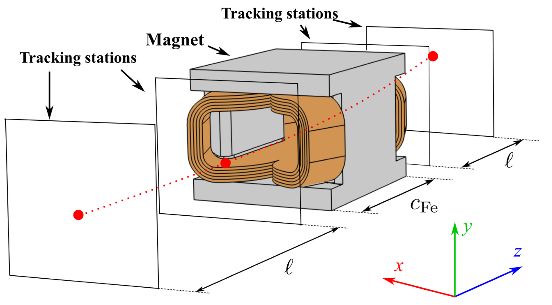
In
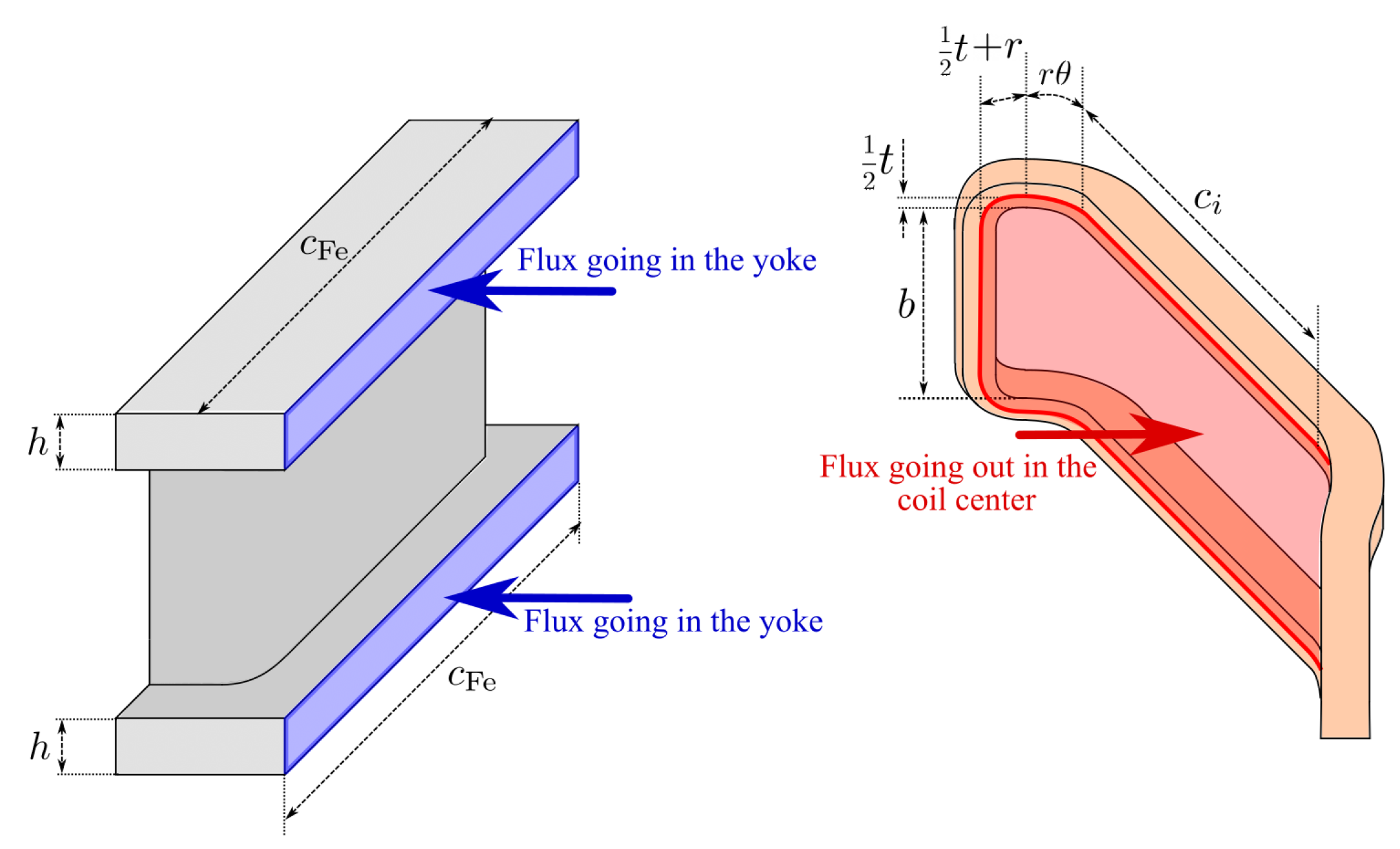
Figure 1, the typical geometry of a magnetic spectrometer is represented, along with a sketch of an open-end air core and iron-dominated magnet. Tracking stations are placed before and after the magnet, where the particles under detection experience bending due to the Lorentz force.
2.1. Constraint Definition
The design specifications of the spectrometer come from the physics requirements, concerning the spectrometer resolution and geometric acceptance, defined henceforth.
The spectrometer resolution
depends on the tracking stations’ resolution
[
15] and the magnet’s bending power. A simple expression commonly used for the design of spectrometers is [
15]
where
is the reference magnetic field in the active region at
;
p and
q are the particle momentum and charge, and
ℓ and
are, respectively, the so-called
lever arm and the effective magnetized path or
magnetic length (as represented in
Figure 1).
Remarkably, the magnetic length
is different from the physical magnet length and, by definition, it satisfies
where
is the longitudinal path of the particle between the trackers. The product
is the magnet bending power.
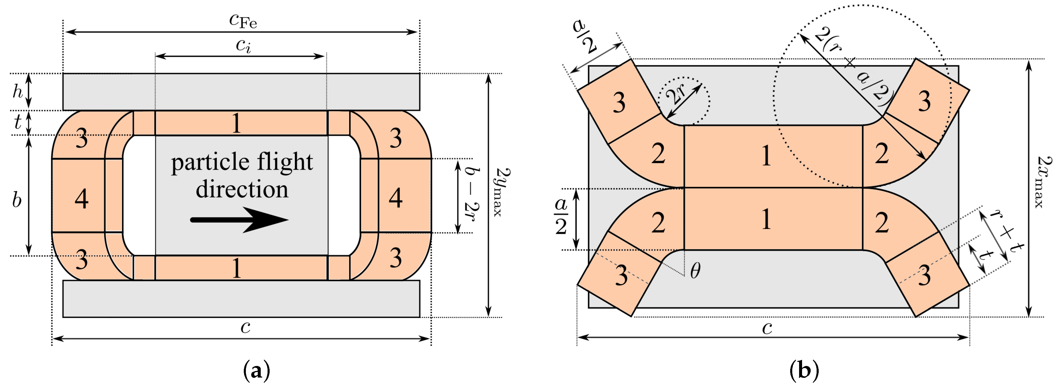
The geometric acceptance, defined as the ratio between the number of particles entering the magnet and the total number of incoming particles, mainly depends on the size and shape of the aperture of the magnet. Hence, the desired value of acceptance is achieved by choosing the lengths
a and
b (shown in
Figure 2) to match the shape of the particle beam.
Besides the physical requirements, further constraints arise from the limited space available. In particular, the total length of the spectrometer
and both the transverse sizes
and
, represented in
Figure 2, are considered.
2.2. Analytical Model and Scaling Laws
The relation between the current, geometry, and field is given by Ampere’s law (see [
11]):
where
is the magnetomotive force,
is the vacuum magnetic permeability,
and
are the magnetic flux density and permeability in the iron, and
a and
t are geometrical dimensions shown in
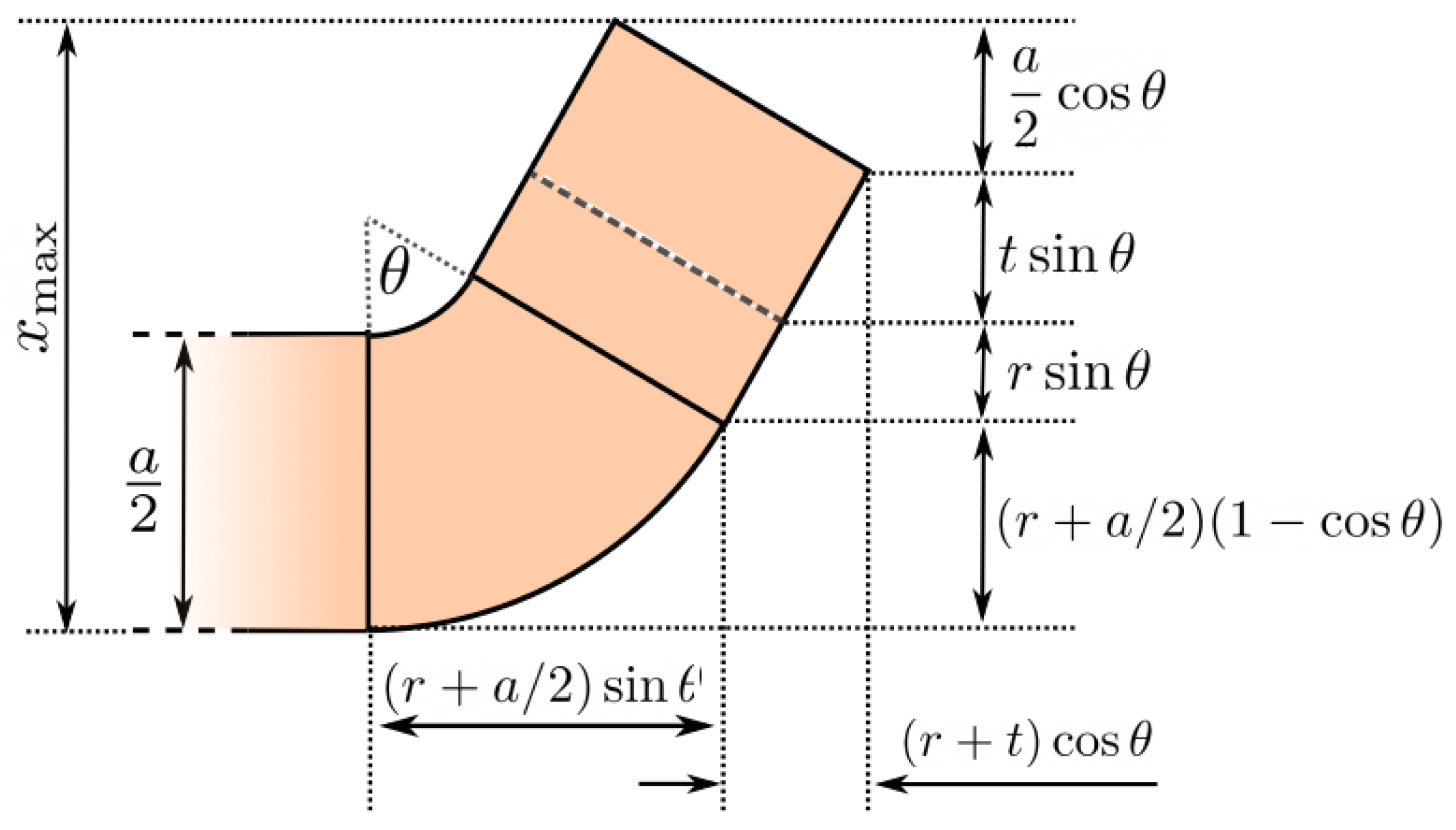
Figure 2.
The electric current density and the electrical power are functions of the magneto-motive force and the magnet geometry:
where
f is the filling factor of the coil,
is the copper electrical resistivity, and
is the volume of the coil.
The exploitation of these scaling laws, optimization parameters, and goals leads to different scenarios, i.e., a general optimization problem. In the following, we choose, as an independent set of optimization variables,
c,
t, and
. Note that the remaining quantities can all be obtained as a function of the independent variables; in particular,
is given by (
1),
is obtained from the flux conservation using
, and
,
J, and
P are given by (
3) and (
4). Further details on the flux balance and magnetic length are given in the
Appendix A.
The variables and constraints of the optimization process are summarized in
Table 1.
For example, the dependence of the electric power upon
t and
is shown in panel (a) of
Figure 3 and the blue dot is the electric power minimum. The power minimum is expected as several competing mechanisms are in play. In particular, a larger coil thickness reduces the current density, which is directly related to the power, but it also reduces the yoke thickness, which eventually causes saturation and increases the reluctance and, consequently, the magneto-motive force. On the other hand, the magnet length affects the product of magnetized length and the lever arms, and hence the intensity of the magnetic field and the magnetized volume.
A different perspective is gained using the total length
L as an optimization variable, with the target function being some combination of
P and
L. The scaling laws of the electric power with the magnet length and the spectrometer length are shown in panel (b) of
Figure 3. The set of points achieving the minimum electric power is represented in the figure by the gray dashed line. As expected, lower power is achieved for higher total lengths
L; in particular, the smaller is
L, the greater is its influence on
P.
At fixed
L, the optimization is executed numerically by varying the three variables in
Table 1. The optimization is not computationally demanding, and it can be performed by evaluating the power consumption over a 3D grid in the variable space (
). Note that the coil thickness
t ranges over a finite set of values as it is, for practical reasons, a multiple of the copper hollow conductors’ thickness (
Table 2). Exploring the variable space, it is found that also the dependence on
c and
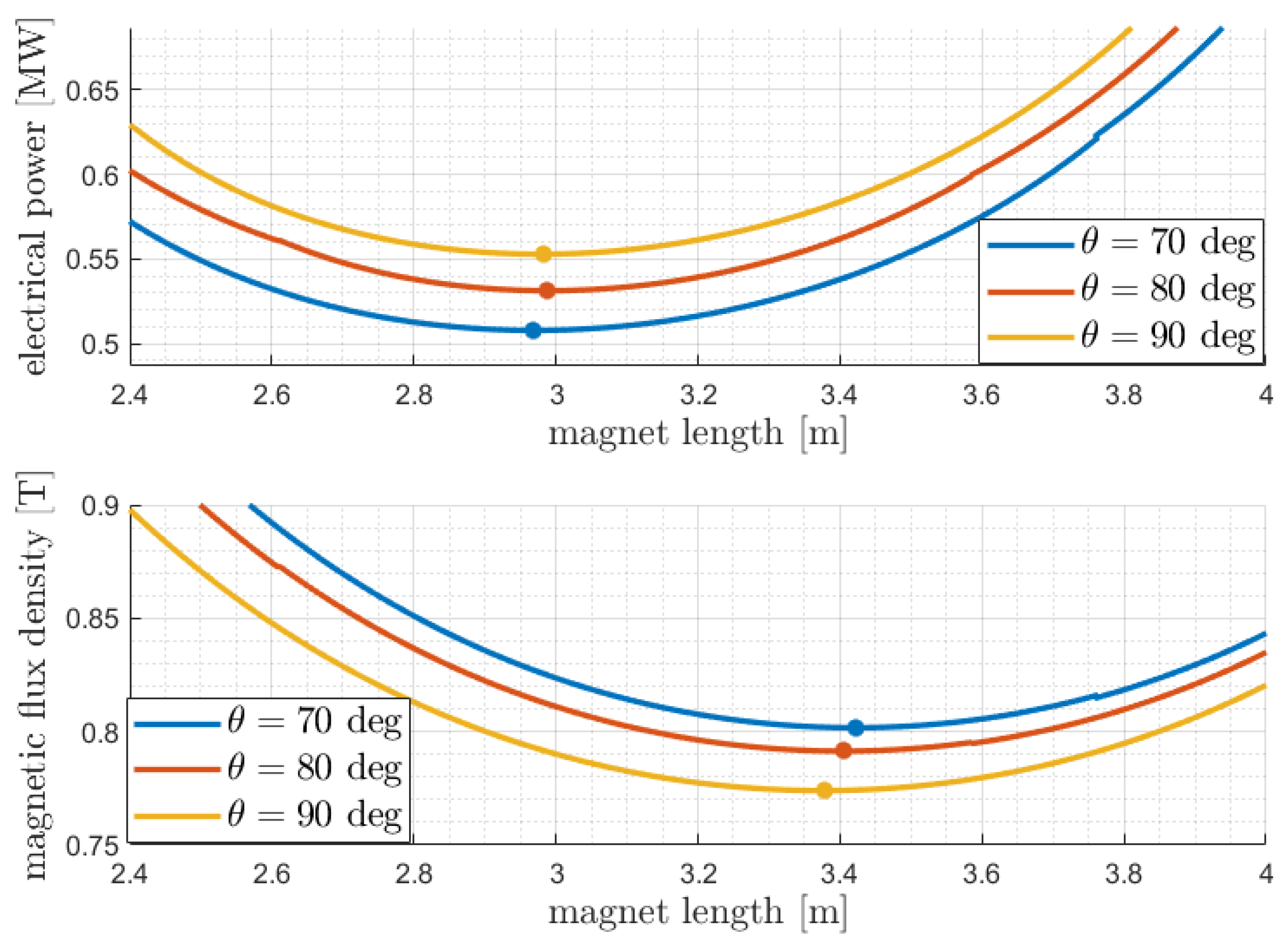
is very smooth and there is no need for complex minimization techniques. The scaling laws for the power and magnetic field are shown in
Figure 4 as a function of the magnet length
for different values of the bending angle
. The dependence on
t is removed by taking, for each
c, the coil thickness that gives the minimum electric power.
Remarkably, the set of parameters providing the power minimum does not give the minimum magnetic field, which is commonly used as a target function when the physical design is performed separately from the engineering design. This discrepancy shows why a unified optimization process including both physical and engineering requirements is preferable.
3. Optimization Results
Two different design cases, marked in the following as the “optimal” design and “bedstead” design, respectively, have been reported here in order to provide an assessment of the advantages achievable and the effectiveness of the proposed procedure. Both cases are the result of optimization but the two solutions mainly differ in terms of the optimization workflow by which they have been obtained. In particular,
the “optimal” design is the result of the joint design and optimization procedure proposed here, which, taking into account, at the same time, physics and engineering aspects as well as geometrical constraints, is able to globally minimize the electrical power consumption;
the “bedstead” design, instead, is the result of a commonly used procedure, where the magnet length c and aperture angle are chosen in order to minimize the flux density B, and only then t is accordingly chosen to minimize the power using B as a constraint.
The main design parameters considered for the reference cases are reported in
Table 2. The table has been structured into four sections in order to allow a better comparison among the most relevant parameters. The first section, named “general magnet properties”, shows that the optimal solution (
deg) offers a shorter magnet length and a much lower total iron mass. Moreover, despite the higher magnetic field available, the optimal design needs total power that is lower than the bedstead solution by about
. This in turn results in a lower operational cost for the magnet, as further detailed in a preliminary cost–benefit analysis presented in
Section 5. The second section presents the main characteristics of the coil. In particular, copper hollow conductors have been considered in order to enable active water cooling of the coil. It is noticeable, furthermore, that in the optimal design case, the total winding length of the coil is about
lower, and this yields an almost proportional reduction in the total hollow bar mass. The next section presents, instead, the “electrical and magnetic properties” of both configurations. The most relevant parameter is probably represented by the voltage needed in the optimal solution, once again more favorable than in the other case. The lower value estimated for the voltage, indeed, leads to a lower cost for the purchase of the power supply. Finally, the last section shows that, in both cases, a simple single pancake configuration could be employed for the efficient water cooling of the coil. In particular, all the cooling parameters fall fully within the operative boundaries usually considered within CERN experiments [
16]. It is worth underlining that a detailed analysis of the coil cooling falls beyond the scope of this paper. However, further details on the configuration adopted here can be found in [
11].
4. Three-Dimensional Electromagnetic Finite Element Analysis Validation
To validate the correctness of the solutions provided by the design and optimization procedure proposed in the previous sections, several configurations are studied and the main results are compared against three-dimensional finite element (FE) electromagnetic models. A 3D FE model, indeed, provides a more realistic design for the final magnet, as well as detailed information on the spatial distribution of magnetic field variables. For the sake of brevity, however, in this paper, we report only the results of the analysis for the two reference cases presented in the previous section.
The magnetostatic problem, which describes the DC steady-state working condition for the magnet, is implemented and numerically solved through the Magnetic Fields interface of the AC/DC module of the COMSOL Multiphysics
® software
[
17]. The finite element problem is formulated in terms of the magnetic vector potential
and solved for the total field [
18,
19]. A Coulomb gauge fixing condition is also added. Before performing the stationary study, a coil geometry analysis, a COMSOL built-in tool, is preliminary performed in order to compute the current flowing within the coil elements.
As a reference material for the iron yoke, we consider AISI1010 steel (the AISI standard is one of the most popular methods of designation in the field of stainless steel [
20]) with nonlinear characteristics, provided by COMSOL, to which we apply scaling on the
B field values by a factor 0.97, so that it matches the specific AISI1010 heat used for the ATLAS experiment at CERN [
21]. Such a scaled
B-
H curve, shown in
Figure 5, was measured at CERN and labeled as ST1010 ATLAS, and it represents the worst case for AISI1010 steel [
11].
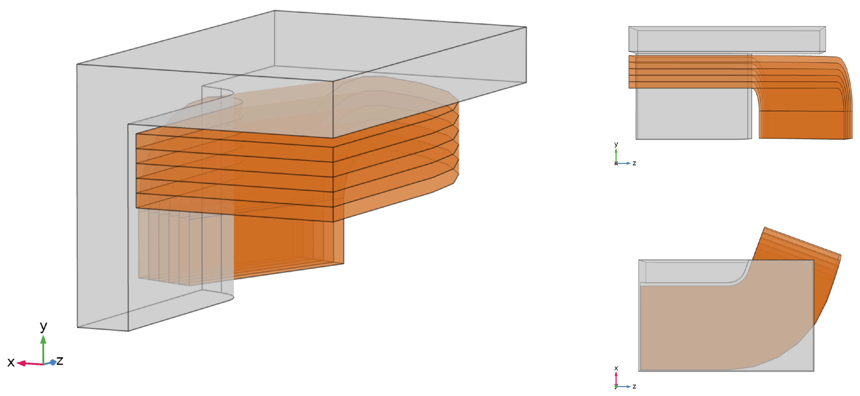
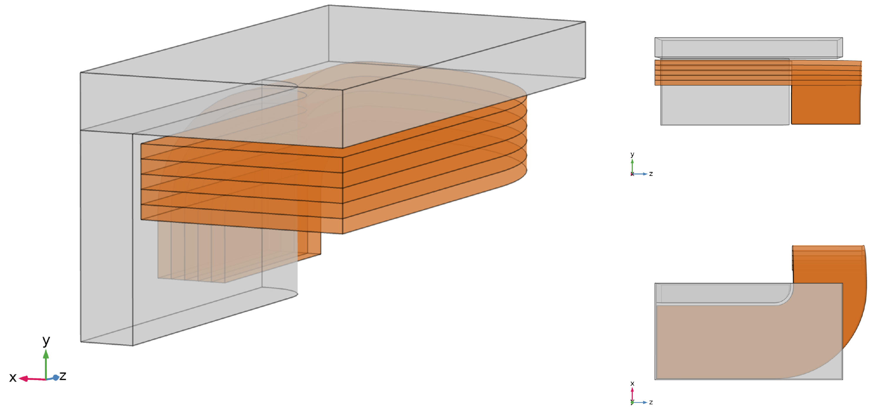
In order to exploit the symmetry of the model, hence reducing the computational burden, only one eighth of the whole structure (hereafter named block) is modeled (
Figure 6 and
Figure 7). On the symmetry plane along the
x-axis, the proper symmetry condition is defined, while a magnetic insulation condition is imposed on the remaining symmetry planes, as well as on the external air region boundary. Moreover, for a more realistic design, we consider the coil to be split into five layers. This choice was made after an inquiry into the commercially available geometrical dimensions for copper hollow conductors (the details are here neglected).
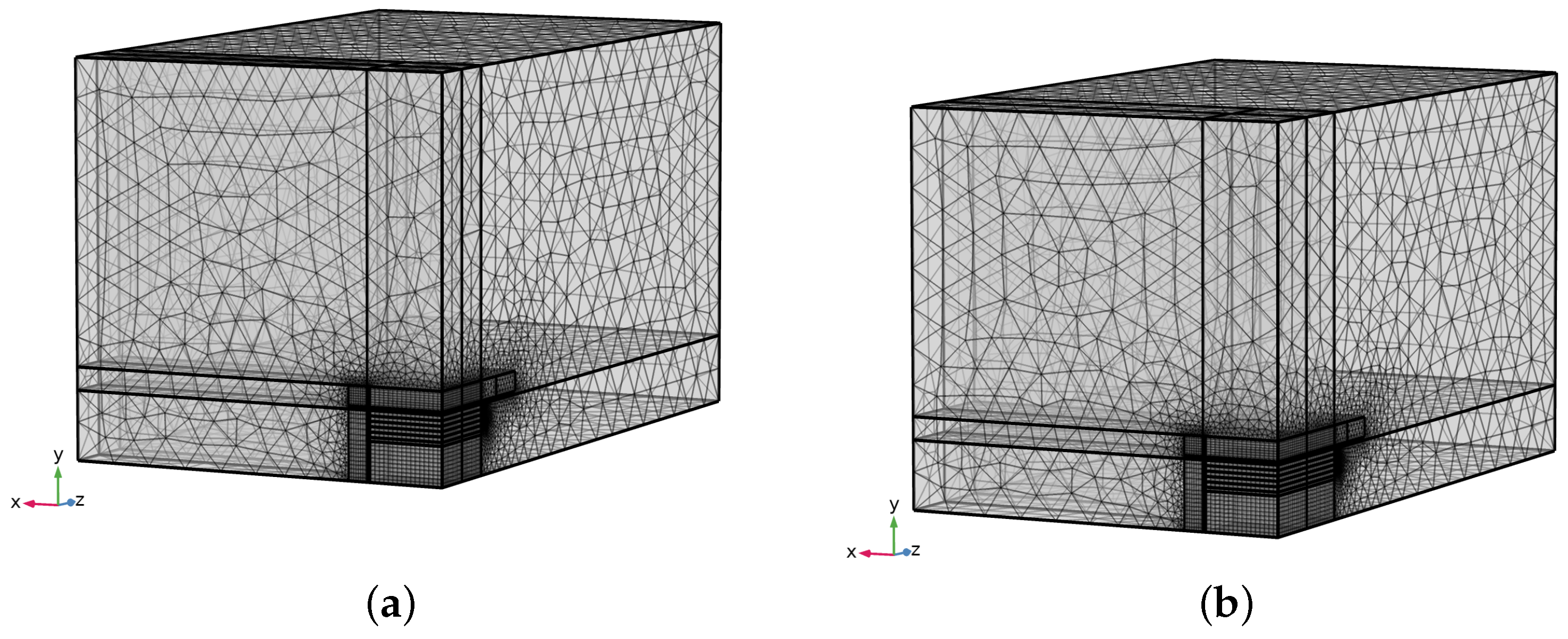
Figure 8 reports the mesh used for the FE analysis of both the reference cases. In particular, for the discretization of the coil and iron yoke domains, as well as for the inner air domain (in correspondence to the straight stretch of the coil), hexahedral elements (bricks) are employed, whereas, in the surrounding air domain, only tetrahedra are considered. The mesh approximately consists of 170,000 elements and 178,000 elements in the “optimal” and “bedstead” design cases, respectively. The simulations, which take about one hour, are performed on a laptop with an Intel
® Core
™ i7-9750H CPU (@2.60 GHz, 64 bit) and 32 GB of RAM.
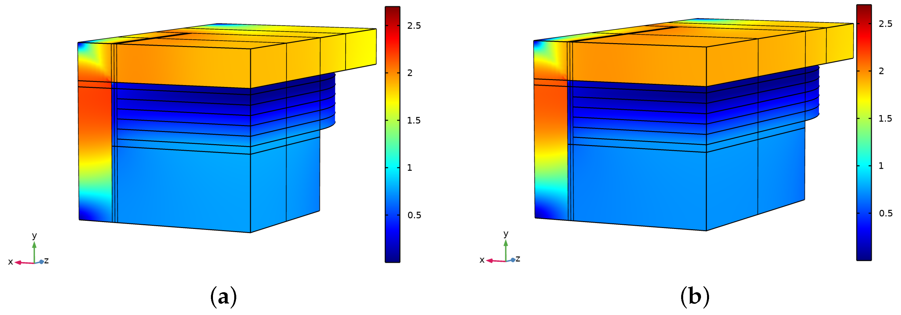
Figure 9 and
Figure 10 show the results of the FEM simulations, in terms of flux density norm
, in 3D and 2D views.
Table 3 and
Table 4 report, for the “optimal” and “bedstead” design cases, respectively, a comparison between the values of the main electromagnetic parameters from the analytic and numeric (3D FE) models. The numeric value of the magnet bending power is computed for a particle traveling at the center of the magnet (
), whereas
is the component of the magnetic flux density along the x-axis at the magnet center (
). It is worth noticing that discrepancies are within 8% by defect, which implies an increase in resolution of 8%.
5. Cost–Benefit Analysis
Some preliminary economical considerations can be drawn as a further advantage of the proposed approach. The operational cost of a spectrometer is mostly given by the cost of the electrical energy used to power the magnet. The proposed design method minimizes the operational cost at fixed performance and spectrometer size. A complete economical analysis must include the construction cost as well, which strongly depends on the cost of the materials, namely the cost of iron and copper for the magnet.
As of today, the average cost (from the Eurostat official website [
22]) of electrical energy in Europe is
€/kWh; however, large laboratories often benefit from special contracts with energy providers and a more realistic price would be in the range
€/kWh. On the basis of previous analyses, the operating cost, expressed in M€ per year, is
where
P is the power consumption of the magnet (expressed in megawatts), and
d is the duty cycle of the magnet, which is defined as the ratio between the time that the magnet is powered on and the total time and strongly depends on the experimental conditions. For example, the particle accelerator could be active only for part of the year, as some weeks may be required for maintenance and the installation of upgrades. A realistic value for the duty cycle is around
.
Similarly, the evaluation of the material costs requires knowledge of the costs of iron
and copper
per kilogram. A reasonable cost for the latter, at the time of writing, is
€/kg, as indicated in [
23]. This price must be adjusted to include transport and manufacturing. On the other hand, due to the many different uses, the cost of iron strongly depends on its type. Assuming
€/kg, the rough cost of the magnet materials is
where the coefficients
and
take into account the costs of manufacturing for iron and copper, respectively; the total volume of copper is calculated in the
Appendix A; and the total volume of iron is
.
The construction costs also include further contingency costs, which are not detailed here, amounting to 10–20% of the total cost of the materials.
Consider the two designs presented in
Section 3. Using the mass of copper and iron in the two compared solutions, given in
Table 2, Equation (
6) yields
€ for the power-optimized design and
€ for the minimum field design.
Remarkably, power-oriented optimization also gives smaller construction costs compared with magnetic-field-oriented optimization. This is a direct consequence of the reduced length of the magnet (see
Figure 4).
Analogously, the power consumption computed with (
5) (using
€/kWh) for the two configurations presented is
€ and
€ for the power-optimized design and the minimum field design, respectively.
The proposed design approach is found to be advantageous for both the construction and operating costs, saving roughly 7.7% of the operating cost and 17.6% of the construction cost.
It is noteworthy that, in less than three years, the operating cost becomes larger that the construction cost. Considering a lifespan of 10 years for the magnet, it is clear that the operating cost is the largest expense by far. The latter consideration holds even more strongly if the hosting laboratory has no special agreement with the energy provider, as the operating cost over 1 year would be greater than the construction cost and, over 10 years, the construction cost would amount to only 5% of the magnet’s costs.
As a matter of principle, the total cost of the magnet (construction and operation) may itself be used as a target function in the optimization if the magnet’s operational lifetime is assumed as input. However, as explained in the Introduction, large facilities and laboratories are subject to strict constraints regarding power consumption; therefore, the power should be carefully estimated, becoming itself a target function.
6. Conclusions
The design of large-aperture iron-dominated magnets is always a complex electromagnetic and engineering task. Nowadays, it is expected that it reflects, besides specific performance constraints, more general sustainability goals, such as minimal electric power and the reduced use of raw materials. This increases the problem’s complexity, calling for new and easy-to-use scaling laws for the involved quantities.
With reference to a challenging case study, namely a new high-energy physics spectrometer, we proposed and derived the main scaling laws of the electric power, magneto-motive force, and magnetic field as functions of the parameters, using them to find a minimal-power solution. Remarkably, we demonstrated that the goal of minimal power, at a fixed total detector length and performance, is attained at a smaller magnet length as compared to the one under the condition of a minimal field. This result clearly shows that if an efficient design is desired, the proposed unified optimization approach, including both physical and engineering requirements, is profitable. Indeed, both the power and use of raw materials are reduced, at fixed performance. By means of comparison, a full multi-dimensional FEM simulation has been carried out for the parameters of the proposed solution, marked as “optimal”, and compared to a standard one, marked as “bedstead”. Besides the confirmation of the gains in the optimized quantities, overall, small discrepancies between the analytical and numerical modeling are found, with relative errors below . Moreover, with respect to the considered case study, a preliminary cost–benefit analysis shows that the solution provided by the proposed procedure leads to savings of about in terms of operating costs and for the construction cost.
As a final and general remark, we have successfully shown that new approaches to large magnet design, including new goals such as power efficiency and reduced size, are feasible and lead to non-trivial solutions and economical cost advantages. Such ideas are, in principle, quite straightforwardly extendable to classes of magnets other than those herein considered.
