Abstract
The internal temperature variation of ballastless track is very complicated under the effect of a sunlit environment, and there are serious transverse and vertical temperature gradients, which will cause cracking and deformation of the structure. In this paper, an ANSYS temperature effect analysis model for ballastless track, considering box girder structure, is established based on the environmental information of the bridge and the characteristics of the structural system. The model considers the influence of solar radiation intensity, wind speed, air temperature, geographical location, bridge orientation, material parameters, and other factors on the boundary conditions, and can meet the needs of the daylight temperature response analysis and calculation of any complex bridge structure. On this basis, the effect and applicability of a solar reflective coating on ballastless track cooling are studied. The results showed that the calculated results of the finite element model agree well with the measured results. Under the high-temperature conditions in summer, sunlight and ambient temperature mainly have significant effects on the temperature and temperature gradient of the track slab, and the maximum vertical temperature gradient reaches 74.48 °C/m. The reflective coating can significantly reduce the track slab’s temperature and vertical temperature gradient, with a maximum temperature gradient reduction of 34%. The transverse temperature gradient of the track slab can be reduced by up to 54% by further application of the side reflective coating. This study can promote the application of reflective coatings on high-speed railway track structures.
1. Introduction
With the development of high-speed railways, the stability and deformation of track structures are more strictly controlled [1], and priority is given to long bridge and ballastless tracks in the design and construction [2]. However, the ballastless track, as a kind of long linear structure, especially the ballastless track on a bridge, is exposed to the atmospheric environment all year round and has the complexity of environmental use. Coupled with the low heat transfer rate of concrete [3], solar radiation and heat exchange cause complex temperature distribution in ballastless track [4], and there are vertical and horizontal nonlinear temperature differences inside, which can lead to the deformation and cracking of structures.
In comparison with the unitary ballastless track, the continuous ballastless track has better integrity and smoothness [5], but it is more affected by temperature [6], and the internal temperature stress is large. Due to the low tensile strength of concrete, this causes cracks in the track’s structure [7]. Meanwhile, ballastless track is used as the basic structure to guide and support high-speed vehicles and has been in a high-frequency vibration environment for a long time [8], which further aggravates concrete cracking. Such a cyclic effect will inevitably affect the durability, stability and security of the structure. Thus, given the current operating environment of continuous ballastless tracks, it is of great significance to study the temperature distribution and cooling measures of these tracks.
In the face of the long exposure to sunshine and high solar radiation energy in summer, control measures such as reducing the speed of high-speed trains and adjusting the train’s running track are usually adopted [9]. These initiatives are detrimental to sustainability and result in more emissions of harmful gases such as carbon dioxide [10]. The rational utilization of solar energy has attracted a great deal of scholarly research [11]. At present, scholars have developed studies on the effects of reflective coating types [12], thickness [13], and the layout optimization of the reflective coatings on structures such as buildings [14], roads [15], track slabs [16], and cement-asphalt mortar layers, etc. The results of such research show that applying a thin layer of reflective coating on the top surface of structural concrete is an effective cooling measure.
For the temperature distribution of ballastless track, the research methods include field experiments, numerical simulation, and theoretical analysis. (1) For field test research, the temperature distribution rule for the simple-supported box girder bridge of high-speed rail is studied under three working conditions: summer, winter, and extremely high temperatures [17]. (2) For the finite element numerical simulation, six types of nonlinear finite element models have been developed, which can accurately simulate the interlayer peeling and damage law of track structures under thermal conditions [18]. (3) For theoretical analysis, a bilinear resistance model was proposed, which can be used to study the interface of large-span bridges under the action of heat [19].
The effect of temperature on the track is mainly related to three major types of factors, such as material factors, climatic factors, and special factors, involving solar physics, general astronomy, meteorological science, heat transfer, track, and other disciplines. Therefore, to more accurately and effectively simulate and analyze the temperature effect and temperature profile characteristics on bridges in different regions, it is necessary to establish a set of fine bridge-ballastless track models based on the environmental parameters and multi-layer characteristics of the track. However, current studies often fail to fully consider the impact of external environmental parameters on ballastless track. Therefore, our aim was to investigate the temperature distribution of ballastless track on a bridge based on environmental parameters and multi-layer track characteristics. Specifically, this study has four main objectives: (1) A thermodynamic model of the continuous ballastless track is created, considering the influence of the box girder structure; (2) The heat transfer mechanism between the bridge and external surroundings is investigated, and the thermal transfer procedure between the concrete and surroundings is classified as solar radiation, heat transfer, or radiation heat transfer, and the three types of thermal transfer are uniformly converted into heat flux boundary conditions; (3) Taking the Changsha area as an example, the temperature distribution characteristics of ballastless track were studied based on summer environmental parameters; (4) Based on the established temperature field analysis, the reflective coating’s effect on the temperature distribution of the track was studied. The results can provide guidance for the design of solar reflective coatings on the ballastless track of high-speed railways. Thus, it is helpful for the popularization and application of ballastless track.
2. Temperature Field of Track Based on Regional Environmental Parameters
2.1. Heat Transfer Equation and Initial Boundary Conditions
The box girder is in a changing natural environment, and its heat transfer state is complex and non-stationary, so its daylight temperature field should be solved as a transient problem. The temperature of the track slab is related to its spatial position, and the temperature field can be expressed as Equation (1).
where is the temperature of node; , , are the spatial position coordinate system; is the time.
Assuming that the concrete material of the bridge structure is isotropic, its thermophysical properties do not change with the temperature, and there is no heat source inside the structure, the basic differential equation of the conductivity of the box girder is as Equation (2) [20].
where is the temperature conduction coefficient .
Figure 1 is a schematic diagram of thermal exchange when the ballastless track on the bridge reaches thermal equilibrium with the external environment.
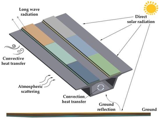
Figure 1.
Schematic diagram of the ballastless track and environmental thermal exchange on the bridge.
Typically, the thermal exchange between the track and the environment can be summarized as solar radiation, radiation heat transfer, and convective heat transfer.
- (1)
- Solar radiation: After the absorption, reflection, and scattering of the Earth’s atmosphere, the solar radiation reaches the surface of the concrete structure, part of which is absorbed by the concrete, and the other part is reflected back. The energy is mainly concentrated in the visible band range, and the wavelength is relatively short, thus, solar radiation is also called short-wave radiation.
- (2)
- Radiation heat transfer: The concrete structure emits heat radiation to the outside in the form of an electromagnetic wave through its surface, and constantly absorbs the heat radiation from the surface, atmosphere, and surrounding objects. The comprehensive result of this radiation and absorption is the radiation heat transfer between the concrete structure and the outside. This form of heat radiation is called long-wave radiation.
- (3)
- Convective heat transfer: When the surface temperature of concrete is different from the surrounding air temperature, the heat transfer between the concrete surface and the surrounding fluid is called convective heat transfer. Convective heat transfer also exists between the air inside the box girder and the inner surface.
2.1.1. Solar Radiation
The solar radiation can be divided into direct solar radiation , Atmospheric scattered radiation , and ground reflected radiation . The total solar radiant energy on any surface is calculated by Equation (3) [21].
where is the solar shortwave radiation absorption rate.
(1) Direct solar radiation
When the angle of solar is , the intensity of the direct solar radiation received is expressed as Equation (4) [21].
where , , are the constant, atmospheric transparency coefficient, and solar altitude angle, respectively. The value of atmospheric transparency is influenced by external factors, such as terrain altitude and air composition, and varies significantly from region to region.
The solar constant depends on the date of calculation and can be calculated using Equation (5) [21].
The sun’s Angle on any day can be obtained by the following empirical Equation (6) [21].
China unified adopts Beijing time as the timekeeping standard, so it needs to go through a longitude revision first to revise Beijing time to local time. Therefore, the true solar time is calculated by Equation (7).
where is the longitude, is the time difference, calculated according to the following the empirical Equation (8) [21].
where is the daily Angle of the change of the daily ordinal number, which can be approximated by Equation (9).
At 12:00 noon in true solar time, the Sun–Earth line is in the same plane as the meridian circle where the observer is located, and the solar time angle is zero at this time. If the solar time angle is defined as positive in the morning, its calculation formula is as follows in Equation (10).
The solar altitude angle and azimuth angle can be calculated according to Equation (11).
where is the geographical latitude of the bridge.
The angle of solar incidence can be obtained by Equation (12).
where is the angle between the inclined plane and the level plane. is the azimuthal angle of the outer normal of the inclined plane.
(2) Atmospheric scattered radiation
During the transfer of the solar radiant energy to the Earth’s surface, taking into account the atmospheric scattering, a part of it reaches the ballastless track surface again. The scattering intensity on the level is calculated according to Equation (13) [20].
The sky scattering intensity on an arbitrary surface is calculated by Equation (14).
(3) Ground reflected radiation
Ground reflected radiation mainly affects the bottom surface of the bridge and the lower edge of the flange plate. Ground reflection can be calculated by Equation (15).
where is the surface short-wave reflectance.
(4) Sunrise and sunset time
Sunrise time and sunset time are the prerequisites for the calculation of solar radiation intensity. The sunrise and sunset time of the vertical surface can be calculated as Equation (16).
For the box girder web surface, the sunrise and sunset time of the vertical surface can be solved, and a set of solutions of solar hour Angle ω can be calculated by Equation (17).
where, is the solar azimuth, and is the sign function. The corresponding true solar time is as Equation (18).
In addition, the moment of sunrise on any surface is not earlier than the moment of sunrise on the vertical surface , and the moment of sunset is not later than the moment of sunset on the vertical surface . Therefore, the moment of sunrise on the web surface of the box beam and the moment of sunset are expressed as Equation (19).
(5) Cantilever shadow calculation
It is necessary to determine the shading length of the web at different moments in the calculation of the radiation, and to remove the energy of the direct part of the radiation from the shaded part in the calculation.
As shown in Figure 2, indicates the cantilever width, indicates the azimuthal angle normal to the outside of the web, and are the solar azimuthal and altitude angles, respectively. According to the geometric relationship shown in the figure, calculating the shaded length of the web can be obtained by Equation (20).
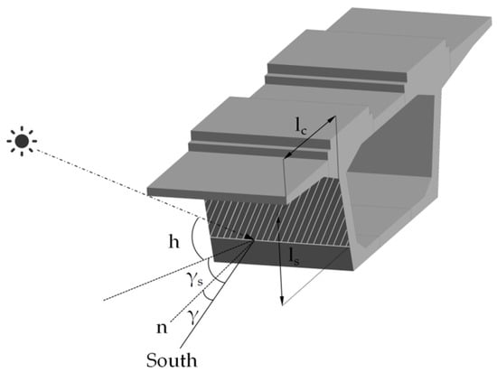
Figure 2.
Schematic diagram of thee cantilever shadow calculation under solar radiation.
2.1.2. Convective Heat Transfer
The convective thermal exchange between the concrete and the atmosphere can be expressed as Equation (21).
where and are the temperature of air and concrete, respectively; is the convective heat transfer coefficient, which is affected by external wind velocity, roughness, inclination, and others, and the most important factor is wind velocity. Therefore, combined with the relevant domestic and foreign research results, when , the can be calculated by Equation (22) [22].
The external temperature is affected by many factors in nature, but the daily variation process of the temperature on sunny days has a good regularity, so many scholars [23,24,25] use the sine function Equation (23) to characterize the change in atmospheric temperature in a day.
where is the average temperature; is the variation of temperature; is the parameter of the time when the maximum and minimum temperatures occur.
2.1.3. Radiation Heat Transfer
Thermal radiation is an electromagnetic wave excited by the thermal motion of microscopic particles inside an object. Generally speaking, the thermal radiation of concrete, whose wavelength range is within the infrared range, is usually called long-wave radiation. The radiant heat transfer of the structure includes absorbed radiation and outward radiation according to the source, and the absorbed heat can be divided into atmospheric radiation and ground radiation. The heat flux from the outside through the concrete surface due to long-wave radiation into the interior can be obtained by Equation (24) [22].
where is the total amount of radiation thermal exchange, with heat absorption as positive and heat release as negative; , and are the atmospheric radiation, ground radiation and structural radiation, respectively.
(1) Atmospheric radiation
Atmospheric radiation has the characteristics of gray body radiation, and the atmospheric radiation heat received by the bridge structure under cloudless weather conditions can be calculated by Equation (25).
where is the atmospheric radiation coefficient, which can be approximated to 0.82 under normal circumstances.
Atmospheric radiation is independent of azimuth. For an arbitrarily inclined surface, the atmospheric radiant thermal exchange capacity is calculated as follows [22]:
(2) Ground radiation
Structures are subjected to longwave radiation emitted by the ground. The radiant heat of the ground on any surface can be determined by the following Equation (27) [22].
(3) Structural radiation
The structure continuously radiates heat outward while absorbing radiant heat from the outside:
where is the concrete long-wave radiation absorption rate, and radiation rate.
2.2. Model Foundation and Validation of CRTS II Slab Ballastless Track
2.2.1. The Model of Temperature Field
The CRTS II slab ballastless track on a bridge is composed of main beam, base plate, CA mortar, and track slab. As shown in Figure 3, considering the influence of the connection between the track slabs on temperature, the model of three track slab lengths was established by ANSYS. Table 1 shows the structure dimensions and calculation parameters.
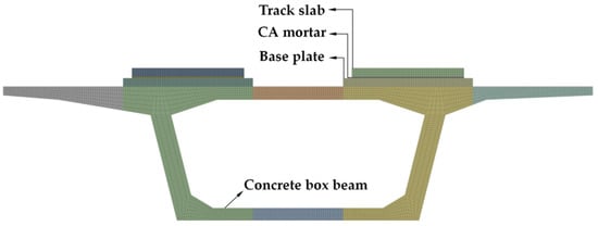
Figure 3.
The temperature field analysis model of ballastless track.

Table 1.
Dimensions and parameters of ballastless track on a bridge.
(1) Initial value
To calculate the temperature distribution of the box girder structure, the initial conditions of heat transfer need to be determined. A transition time calculation process was added to reduce the impact of the initial value on the numerical analysis. In this paper, the average temperature on the first day was defined as the initial value.
(2) Boundary conditions
The boundary thermal exchange on the outer surface of the box girder consists of solar radiation, convective thermal exchange, and radiative thermal exchange, so the total heat transfer boundary conditions can be expressed by Equation (29).
In this paper, the temperature boundary is transformed into the second type of boundary conditions for solving:
where is the total heat flux at the boundary of . The shielding effect of the flange should be considered in the calculation of box girder web temperature. The general finite element software ANSYS has a powerful function of thermodynamic analysis, which can store the boundary heat flux into a multidimensional data table indexed by coordinates, time, and temperature. When loading the heat flow boundary conditions, ANSYS can automatically index the value of the corresponding position in the table for loading. At the same time, it can automatically adjust the size of the table according to the different periods, temperature amplitude, and heat conduction dimensions. The shading effect of the cantilever plate on the web was considered by cyclic solution.
According to the existing studies, it is assumed that the temperature difference of the internal air in the box girder is minor in one day, and it is 1.5 °C higher than the average temperature.
2.2.2. Model Verification
The environmental parameters from the literature [26] were substituted to verify the calculation accuracy of the finite element model; the comparison between the calculated results and the measured data is shown in Figure 4. The measured data are the continuous monitoring results of two temperature measuring points on ballastless track (28° N, 113° E). The calculated temperature time is 5 October 2013, and the highest and lowest temperatures are 27.6 °C and 18.1 °C. The numerical simulation results are essentially consistent with the measured data, with good agreement and slight errors. The results showed that the finite element simulation of the temperature field was reliable.
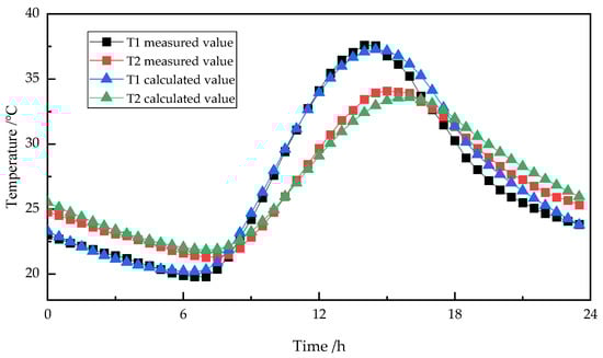
Figure 4.
The calculated values of the daily temperature distribution curves are compared with the measured values.
2.2.3. Ballastless Track Temperature Field in Changsha
The Changsha region of China has a subtropical monsoon climate with abundant sunshine and rainfall. It is a typically hot region in summer. Summer temperature, solar radiation, and wind speed have the following characteristics:
- (1)
- The daytime temperature is higher, and the temperature rise and fall rate are faster, the large temperature difference between day and night, and the track slab, makes it easy to produce a larger temperature gradient and deformation.
- (2)
- Strong solar radiation, up to 1000 W/m2 or more, makes the track slab produce a large positive temperature gradient, which makes it easy to produce track slab warping.
- (3)
- The wind speed in the Changsha area is between 1 m/s to 2 m/s in summer, and the wind speed is low, which is not conducive to the release of heat from the track slab.
Therefore, the phenomenon of a high track temperature in summer is extremely common in this region, and it is also very suitable for the promotion of cooling coatings. Taking the summer environment in Changsha area as an example, this paper analyzes the temperature distribution of tracks using ANSYS.
By analyzing the average temperature change of Changsha Mapoling station (28°2′ N, 113°8′ E) over the past 60 years from 1951 to 2010 [27], the highest and lowest summer temperatures in the Changsha area over the past 60 years can be obtained as 24.4 °C and 32.5 °C, respectively. The analysis time is assumed to be 15 July 2013, with clear skies, few clouds, and low wind speed (2.2 m/s); using the above environmental parameters as the known conditions, the initial moment is taken as 26 °C, and the first 5 d are used as the trial calculation process to reduce the error introduced by inaccurate initial conditions. The transient calculation is performed for the whole 120 h, the interval is 0.5 h. The ballastless track and material parameters are the same as in the previous modeling.
3. Results and Discussion
3.1. The Temperature Distribution Characteristics of CRTS II Slab Ballastless Track
As shown in Figure 5, the middle cross-section of ballastless track in the Changsha area for a range of times on 15 July 2013, were obtained by finite element calculation.
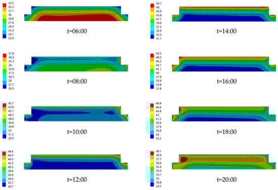
Figure 5.
Temperature nodal data of ballastless track section for a range of times.
The temperature variation of the track slab is more obvious in the daytime solar irradiation environment, and the vertical and transverse temperature difference on the track slab are obvious. During sunrise and sunset, the corresponding temperature shift patterns are shown. The temperature of the base plate changes slowly. The transverse temperature difference is obvious, larger than the vertical direction. During the period from 0:00 to 6:00, the temperature of the ballastless track is higher than the outside temperature. The thermal exchange of the structure is mainly for radiating heat to the outside, and convection heat dissipates with the air. The internal temperature is higher than the temperature of the surface, and the temperature increases with the distance from the structural surface.
During the period from 6:00 to 12:00, the sun rises from the east side, and the temperature of the track slab increases with the increase in outside temperature, and becomes a positive temperature gradient of hot up and cold down. However, the surface temperature of the track slab rises faster than that of the interior. The vertical temperature gradient of the track slab is higher, and the temperature of the east side is higher than that of the west side, so the transverse temperature gradient is gradually increasing.
At 15:00, the sun reaches over the structure. At this time, the solar radiation intensity reaches its maximum, and the vertical temperature gradient of the track structure increases, while the transverse temperature gradient decreases.
From 15:00 to 20:00, when the sun sets in the west, the solar radiation decreases, and the temperature of the track structure decreases. At this time, the radiation quantity of the west side is higher than that of the east side, and the vertical temperature difference decreases while the transverse temperature difference increases.
After about 20:00, the outside temperature decreases, and the track structure experiences external heat exchange; the internal temperature becomes gradually higher than the surface temperature.
3.2. Vertical Temperature and Temperature Gradient
Five measurement points at the locations shown in Figure 6a were selected to analyze the temperature field. M − 1, M − 2, and M − 3 represent the upper, middle and bottom positions of the track slab, respectively, and MM − 4 and MM − 5 are the locations of the bottom of the CA mortar and base plate, respectively. The time course curves of the temperature variation of each measurement point at different depths and the temperature gradient of each structural layer are shown in Figure 6.
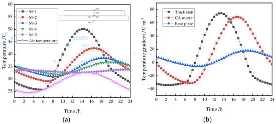
Figure 6.
The daily distribution curve of (a) Vertical temperature and (b) Vertical temperature gradient.
It can be seen from Figure 6a that the temperature inside the track decreases with the increase in depth, and there is a time-lag phenomenon. With the change in atmospheric temperature during the day, the ballastless track shows different temperature response rules.
The heat transfer rate between the surface of the track slab and the outside world is rapid, which is evidently affected by the temperature shift. The upper surface temperature rises from around 06:00 and reaches its maximum at 15:00. The highest and lowest temperatures are 50.12 °C and 25.70 °C respectively. The highest temperature of the track slab surface is 17.62 °C higher than that of the outside. The temperature in the middle of the plate (10 cm from the surface) reached its maximum at about 16:30, with a lag time of about 2.5 h. The highest and lowest temperatures were 42.39 °C and 29.11 °C, respectively. The bottom temperature reaches its maximum at about 18:30, the lag time is about 4.5 h, the highest temperature is 38.45 °C, and the lowest temperature is 31.05 °C. At 13:30, the temperature difference of the track slab reached 14.86 °C.
Because the CA mortar layer is thin, the upper and lower surface temperature distribution hardly changes. The temperature change of the base plate is relatively mild, lagging behind the temperature change of the track slab. The highest and lowest temperatures on the upper surface of the base plate are 36.74 °C and 31.80 °C, respectively, and the corresponding time is about 19:30 and 9:00. The maximum daily temperature variation of the base plate is only 4.94 °C, and the maximum temperature of the base plate is only 4.24 °C higher than the maximum ambient temperature. Due to the covering effect of the track slab, the base plate tends to have a flat temperature curve, without extreme temperature. The results in Figure 6b show that the temperature gradient of each layer changes periodically with time. Among them, the temperature gradient of the track slab and CA mortar changed more clearly.
From 8:00 to 18:00, the track slab mainly presents a positive temperature gradient state of hot up and cold down, and a negative temperature gradient state at other times. The highest and lowest temperature gradients are 74.48 °C/m and −33.82 °C/m, respectively, and the corresponding time is about 13:30 and 02:30, respectively. The maximum diurnal variation range of the temperature gradient of the track slab can reach 108.30 °C/m.
The CA mortar layer is in a positive temperature gradient state from 11:00–23:00, and in a negative temperature gradient state at other times. The highest and lowest temperatures are 68.93 °C/m and −31.33 °C/m, respectively, and the corresponding time is about 16:30 and 07:00, respectively. The maximum diurnal variation of the temperature gradient is 100.26 °C/m. The vertical temperature curve of the base plate is extremely gentle. The highest and lowest temperatures are 17.97 °C/m and −5.67 ℃/m, respectively, and the corresponding time is about 19:00 and 08:30, respectively. The diurnal range of the temperature gradient is only 23.64 °C /m.
3.3. Transverse Temperature and Temperature Gradient
The distribution of the measuring points of the transverse temperature on the track structure is shown in Figure 7a. The reference plane is defined as the middle cross-section of the track slab. Figure 7 is the daily variation distribution curve of the transverse temperature and temperature gradient of the track slab.
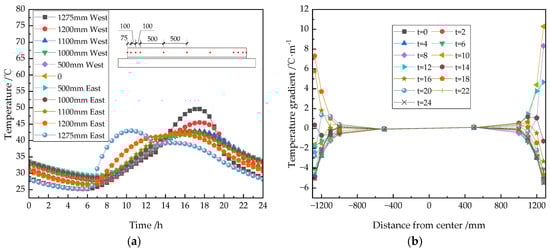
Figure 7.
The daily distribution curve of (a) Transverse temperature and (b) Transverse temperature gradient.
The results in Figure 7a show that the daily temperature on the east and west sides of the track slab varies highly within the range of about 100 mm, and the temperature on the west side is higher than that on the east side. There was a slight difference in the temperature variation at additional measuring points. With the changes in atmospheric temperature and sunshine time, the track slab shows different temperature response patterns in the transverse direction. In the period of 0:00–6:00, there is no obvious difference in the temperature distribution between the east and west areas of the track slab. During 6:00–13:00, the temperature in the east area is higher than that in the west area; from 13:00–15:00, the transverse temperature distribution is uniform. During 15:00–19:00, the temperature in the west area is higher than that in the east area, and from 18:00–24:00, the trend of temperature change in the east and west is the same, and the temperature in the west is higher than that in the east.
The results in Figure 7b show that the transverse temperature varies significantly within the 200 mm range on both sides of the track slab. In other areas, the temperature changes are relatively flat. For example, the daily temperature gradient within 200 mm from the east and west sides is −5.47~10.29 °C/m, and the range of temperature variation on the east side is slightly larger than that on the west side. The daily temperature gradient in the range of 1000 mm from the center is only −0.56~0.54 °C/m. The vertical temperature gradient is relatively tiny, and the highest vertical temperature gradient is 7.24 times the highest transverse temperature gradient.
With the change in atmospheric temperature and sunshine time, the transverse temperature shows different patterns. From 0:00 to 6:00, the distribution of the temperature gradient on the east and west edges is very similar; at 8:00, the temperature gradient on the east edge changes from negative to positive, while the temperature gradient on the west side is still negative at this time; at 10:00, the transverse temperature gradient on the east side reaches the maximum value of 10.29 °C/m. From 20:00–24:00, the temperature distribution on the transverse side was similar to that at 0:00–6:00.
3.4. Effect of Reflective Coating on the Temperature Field of Ballastless Track
The temperature field model of ballastless track was established and its reliability was verified. In this section, the effect of the coatings on track structure cooling was discussed by means of the material parameters of the coatings used in the field, and the applicability of the side coating was studied.
3.4.1. Determination of Coating Parameters
According to the principle of temperature reduction, there are two types of coatings: reflective and barrier coatings. The thickness of a barrier coating is normally 5–20 mm, which is a thick film coating, and the high thermal resistance of the coating itself slows down heat transfer to achieve a heat insulation function. Reflective coatings are made by adding highly reflective functional fillers to the coating to achieve cooling by reflecting sunlight.
The main source of heat for a ballastless track is solar radiation, so this paper takes reflective coating as an example to study the temperature effect of a cooling coating on the structure of ballastless track. The radiation that shines onto the surface of the track structure is partly reflected and partly absorbed. The radiation absorption coefficient of an ordinary ballastless track surface is about 0.65. The reflective coating has a strong reflective ability against radiation, according to the literature [28]; its reflectivity is greater than or equal to 0.8, and its absorption coefficient is less than 0.2. However, due to the influence of construction conditions, concrete property differences, atmospheric oxidation, and ultraviolet aging, the reflective ability and radiation emission ability of the coating are weakened. In this paper, the reflective coating parameters determined by Kang Weixin [29] by back-calculation through tests are referred to; the solar radiation absorption coefficient of the coatings was 0.37 and the blackness coefficient was 0.82. The thickness of the reflective coatings was thin, so it was ignored in the modeling. The radiation was multiplied by the corresponding absorption coefficient and added to the surface of the ballastless track as a heat flow density load in the calculation. The painting method is shown in Figure 8.
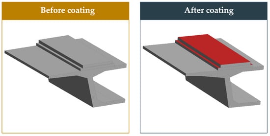
Figure 8.
Reflective coating application method.
3.4.2. Effect of Coating on Temperature of Track Structure
According to the analysis of the temperature field, the highest temperature of the track appears at 15:00. Figure 9 shows the temperature distribution cloud of the track section, before and after coating, at a typical time on 15 July 2013.
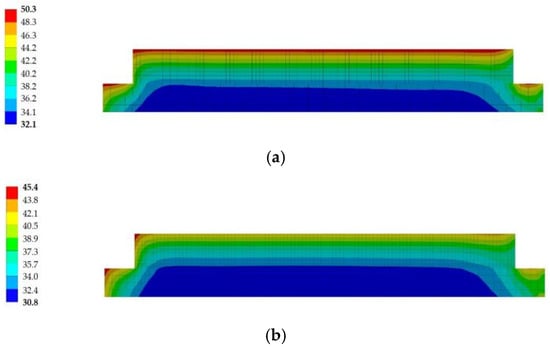
Figure 9.
Cross-section temperature distribution at 15:00 (a) Without coating and (b) Coating on the upper surface.
As can be seen from Figure 9, the upper surface reflective coating affects the temperature of the track slab and has a minor effect on the temperature of the base plate. The variation rule of the temperature of ballastless track is similar to that without coating, but the minimum temperature and maximum temperature are reduced, the temperature distribution form changes slightly, the high-temperature area of the track slab decreases, and the vertical temperature decreases, evidently.
The application effect of the reflective coating was analyzed by the curves of the center temperature of the upper, middle, and lower surface of the track slab, the lower surface temperature of the CA mortar layer, and the base plate. The temperature variation curves for each depth of the track slab is shown in Figure 10.
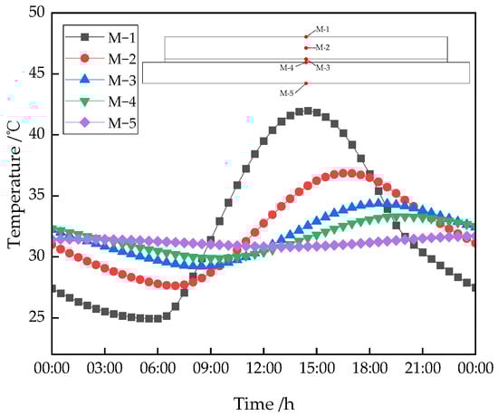
Figure 10.
The daily distribution curve for vertical temperature.
By comparison with Figure 6a and Figure 10, the maximum temperature of the upper surface, middle and lower surface of the track slab decreased by 8.23 °C, 5.12 °C, and 3.31 °C, respectively, at 15:00. This shows that the reflective coating has an obvious influence on the middle region of the track slab and the remaining areas are not obvious. According to Figure 10, the percentage decrease in the daily maximum temperature and average daily temperature at each measuring point are calculated, and the results are shown in Table 2.
Table 2.
Effect of the solar heat reflective coating at typical depths.
As can be seen from Table 2, the reflective coating can significantly reduce the maximum temperature and average temperature of the structures; it is especially effective at weakening the peak temperature of the structure. The cooling effect of the coating on ballastless track decreases with the increase in structural depth, but the effect on the average temperature is tiny.
3.4.3. Effect of Coating on the Temperature Gradient of the Track Structure
The analysis results show that the maximum vertical positive temperature and negative temperature of the ballastless track appear at 13:30 and 02:30, respectively. The effect of the reflective coating on the vertical temperature gradient was analyzed at these two time points. Figure 11 shows the temperature curves of each measuring point before and after using the reflective coating.
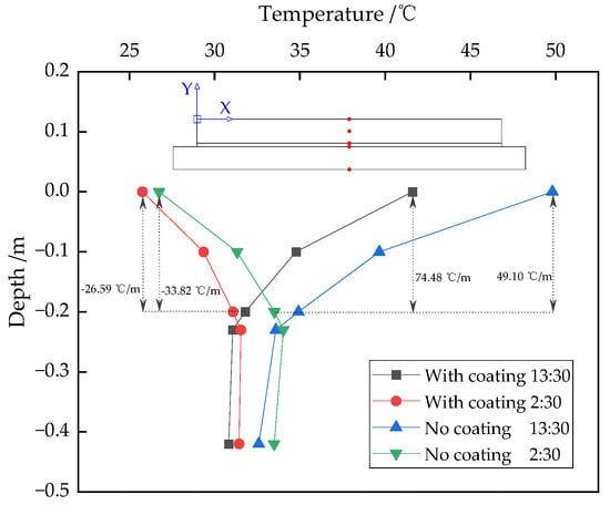
Figure 11.
Vertical temperature distribution of ballastless track at typical moments before and after the use of coatings.
As can be seen from Figure 11, the reflective coating has a significant effect on the temperature and temperature gradient of the track slab, both of which are reduced. The maximum positive temperature of the track board was reduced by 34% and the maximum negative temperature by 21%.
Figure 12 shows the daily distribution curve of the transverse temperature gradient after using the coating. Compared with Figure 7b, it can be seen that the reflective coating reduces the transverse temperature of the plate. The maximum negative temperature decreased from −5.47 °C to −2.91 °C. The maximum transverse temperature was reduced from −5.47 °C to −2.91 °C, and the maximum positive temperature was reduced from 10.29 °C to 9.27 °C. Therefore, the reflective coatings do not change the transverse temperature significantly.
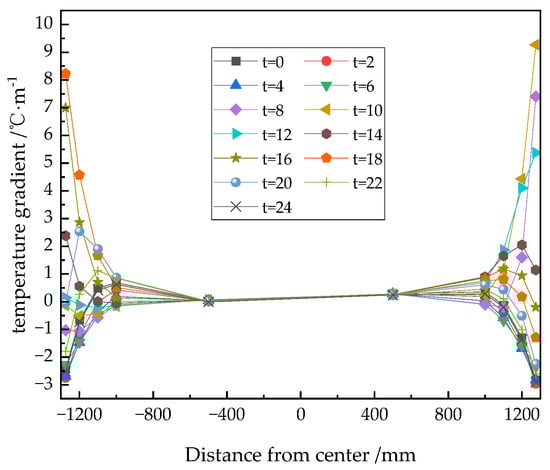
Figure 12.
The diurnal distribution curve of the transverse temperature gradient of ballastless track after using a coating.
3.4.4. Effect of Side Coating on Track Structure
The ballastless track side surface area is tiny and receives relatively less solar radiation, and the cost of reflective coating is expensive. Therefore, it is necessary to analyze whether the side of the track needs to be coated with reflective coating. Firstly, it is necessary to understand the intensity of the solar radiation that can be received by the side surface. According to the reference values of solar radiation in the Changsha area in the thermal design code for civil buildings [30], the solar radiation intensity on the south-facing (S) and north-facing (N) surfaces in the Changsha area is low, and the strongest does not exceed 350 W/m2. Therefore, if the track is oriented east-west, there is no need to use coatings on its two side surfaces. If the track structure is oriented north-south, the intensity on the east-west is strongest at 16:00, and radiation intensity is about 1000 W/m2. Figure 13 is the temperature distribution clouds before and after using a reflective coating on the side of ballastless track at 16:00.
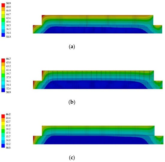
Figure 13.
Cross-section of the temperature distribution at 16:00 (a) Without coating, (b) Coating on upper surface, and (c) Coating on upper surface and side.
As shown in Figure 13, the influence of side reflective coating on the temperature distribution is not obvious, mainly affecting the western surface’s temperature. The temperature and temperature gradient of the side area decreased after the use of a reflective coating on the side. To more obviously show the degree of influence of a side coating on the vertical and transverse distribution of the track temperature before and after coating, the temperature changes of measuring points at different positions on the west surface and upper surface were selected for analysis, as shown in Figure 14 and Figure 15.
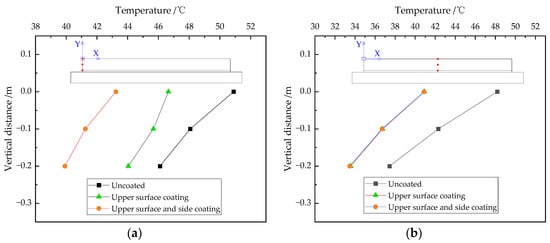
Figure 14.
The vertical temperature distribution before and after side coating (a) On the west side and (b) In the middle.
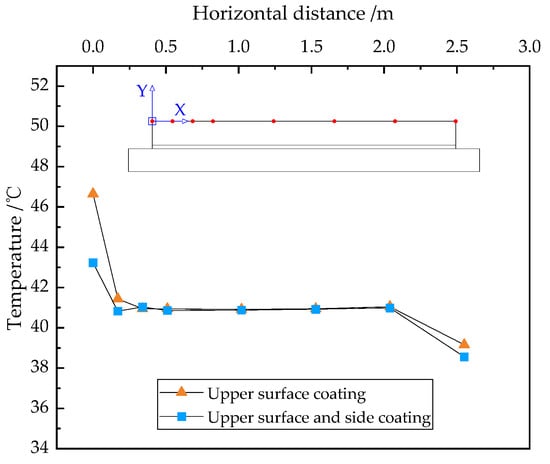
Figure 15.
The transverse temperature distribution of the upper surface before and after side coating.
Figure 14a shows that the use of a reflective coating on the side can further reduce the vertical temperature on the side. The temperature reduction effect does not differ considerably at different depths, and the average temperature reduction is about 9%. Figure 14b shows that the coating has a slight influence on the temperature of the vertical measuring point in the middle of the track slab. Therefore, the side reflective coating mainly reduces the vertical temperature of the side of the track slab and has a limited effect on other areas.
Figure 15 shows that the effect of the reflective side coating on the transverse temperature is mainly concentrated in the range of 200 mm. In this range, the transverse temperature is reduced from 46.65 °C to 43.23 °C. The transverse temperature gradient was reduced from a maximum of 30.66 °C/m to 14.13 °C/m, a reduction of 54%. The transverse temperature and temperature gradient in other areas did not alter significantly. Although the temperature reduction effect of the reflective side coating is not obvious, it can significantly improve the transverse temperature gradient in the side edge area, thus reducing cracking disease at the edge of the slab.
4. Conclusions
Based on the theories of solar physics, general astronomy, and heat transfer, the mechanism of heat transfer between concrete bridges and the external environment was analyzed. Further, the boundary conditions for the analysis of the sunlight temperature field upon ballastless track structures on bridges were systematically established. Finally, the solar irradiation temperature field model of continuous ballastless track, considering a box girder structure, was established based on ANSYS, and the accuracy of the thermodynamic model was verified. The effect of a reflective coating on ballastless track on a bridge was discussed. The following conclusions were drawn.
- (1)
- The thermal exchange between a ballastless track and the environment is divided into three categories: solar radiation, convective heat transfer, and radiation heat transfer, and then converted into heat flux boundary conditions related to time, surface temperature, and coordinates. This model can consider the influence of meteorological conditions, time, and the geographical locations of ballastless track, fully. The model’s results were compared with the measured data, and the error meets the requirements of temperature analysis. The parametric study showed that the intensity of solar radiation is the most important factor affecting the temperature difference of the structure.
- (2)
- The heat transfer boundary conditions established in this paper can be used to analyze and calculate the sunlight temperature response of complex concrete bridge structures in any area. Taking the Changsha area as an example, the sunlight temperature effect upon ballastless track in summer was analyzed. The results show that the temperature of the track slab varies significantly with the external temperature and time, while the internal temperature has a certain time lag. The highest vertical temperature of ballastless track in the Changsha area in summer is 7.24 times that of the highest transverse temperature. The highest vertical temperature gradient is 74.48 °C/m, which occurs at 13:30.
- (3)
- The ANSYS was used to simulate the application effect of a reflective coating under high temperature in summer in the Changsha area. The coating was found to have a cooling effect on ballastless track. The coating mainly acts on the middle and upper areas of the track’s slab. The coating on the surface of the track slab can reduce the maximum and vertical temperature of the surface.
- (4)
- If the track is north-south, applying a reflective coating to the side of the track has little effect on the overall temperature, but can significantly reduce the transverse temperature gradient in the edge region of the track side by up to 54%.
The research on sunlight’s temperature effect and the control measures of a ballastless track on a bridge has the characteristics of complexity and multidisciplinary intersections. In this paper, we have performed some basic research work on the model’s establishment and completed a calculation analysis of the sunlight’s temperature effect, but there are still many problems to be studied in more depth.
- (1)
- Study on the calculation method of the temperature field considering interlayer cracking separation and its influence on the cooling effect of the coating.
- (2)
- Study on the effect of the coating’s cooling effect under the combination of sunlight’s temperature effect and other loading effects.
- (3)
- Study on the effect of wind speed and other factors on the cooling effect of coatings.
Author Contributions
Methodology, X.Q. and W.G.; Software, W.Z.; Writing – original draft, X.Q. and W.G.; Funding acquisition, J.T. All authors have read and agreed to the published version of the manuscript.
Funding
This work was financially supported by the National Natural Science Foundation of China (No. 52078489).
Institutional Review Board Statement
Not applicable.
Informed Consent Statement
Not applicable.
Data Availability Statement
Data are contained within the article. They are also available on request from the main and the corresponding authors.
Conflicts of Interest
The authors declare no conflict of interest.
References
- Edwards, J.R.; Mechitov, K.A.; Barbosa, I.G.; Lima, A.D.; Spencer, B.F.; Tutumluer, E.; Dersch, M.S. A Roadmap for Sustainable Smart Track-Wireless Continuous Monitoring of Railway Track Condition. Sustainability 2021, 13, 7456. [Google Scholar] [CrossRef]
- Hsu, W.K.; Shih, N.H.; Lee, Y.L. Railway Continuous Prestressed Concrete Bridge Design in Ballastless Track Turnout Zones. Technologies 2017, 5, 11. [Google Scholar] [CrossRef]
- Cho, H.C.; Han, S.J.; Heo, I.; Kang, H.; Kang, W.H.; Kim, K.S. Heating Temperature Prediction of Concrete Structure Damaged by Fire Using a Bayesian Approach. Sustainability 2020, 12, 4225. [Google Scholar] [CrossRef]
- Yang, R.S.; Li, J.L.; Kang, W.X.; Liu, X.Y.; Cao, S.H. Temperature Characteristics Analysis of the Ballastless Track under Continuous Hot Weather. J. Transp. Eng. Part A Syst. 2017, 143, 04017048. [Google Scholar] [CrossRef]
- Su, M.; Dai, G.L.; Marx, S.; Liu, W.S.; Zhang, S.S. A Brief Review of Developments and Challenges for High-speed Rail Bridges in China and Germany. Struct. Eng. Int. 2019, 29, 160–166. [Google Scholar] [CrossRef]
- Liu, Y.; Yi, X.; Huang, J.C.; Zhao, G.T. Experimental Research on Temperature Field of CRTS II Slab Ballastless Track Structure. In Proceedings of the Construction and Maintenance of Railway Infrastructure in Complex Environment, Beijing, China, 2–3 August 2014. [Google Scholar]
- Xu, Y.D.; Yan, D.B.; Zhu, W.J.; Zhou, Y. Study on the mechanical performance and interface damage of CRTS II slab track with debonding repairment. Constr. Build. Mater. 2020, 257, 119600. [Google Scholar] [CrossRef]
- Xiao, H.; Zhang, Y.R.; Li, Q.H.; Jin, F.; Nadakatti, M.M. Analysis of the initiation and propagation of fatigue cracks in the CRTS II slab track inter-layer using FE-SAFE and XFEM. Proc. Inst. Mech. Eng. Part F J. Rail Rapid Transit 2019, 233, 678–690. [Google Scholar] [CrossRef]
- Hwang, S.H.; Kim, S.; Lee, K.C.; Jang, S.Y. Effects of Long-Wavelength Track Irregularities Due to Thermal Deformations of Railway Bridge on Dynamic Response of Running Train. Appl. Sci. 2018, 8, 2549. [Google Scholar] [CrossRef]
- Sher, F.; Hazafa, A.; Marintseva, K.; Rasheed, T.; Ali, U.; Rashid, T.; Babu, A.; Khzouz, M. Fully solar powered Doncaster Sheffield Airport: Energy evaluation, glare analysis and CO2 mitigation. Sustain. Energy Technol. Assess. 2021, 45, 101122. [Google Scholar] [CrossRef]
- Ullah, S.; Branquinho, R.; Mateus, T.; Martins, R.; Fortunato, E.; Rasheed, T.; Sher, F. Solution Combustion Synthesis of Transparent Conducting Thin Films for Sustainable Photovoltaic Applications. Sustainability 2020, 12, 10423. [Google Scholar] [CrossRef]
- Li, Y.; Chen, J.J.; Wang, J.X.; Shi, X.F.; Wang, R. Study on the effects of solar reflective coatings on the interfacial damage of the CRTS II slab track. Constr. Build. Mater. 2022, 325, 126711. [Google Scholar] [CrossRef]
- Zhang, J.W.; Jiang, H.L.; Ding, F.; Zhang, P.Z.; Zhou, F.; Li, T.; Duan, N. Effects of metal-ceramic anticorrosion coating on the performance of ballastless tracks at high temperature. Arch. Civ. Mech. Eng. 2020, 20, 120. [Google Scholar] [CrossRef]
- Synnefa, A.; Santamouris, M.; Akbari, H. Estimating the effect of using cool coatings on energy loads and thermal comfort in residential buildings in various climatic conditions. Energy Build. 2007, 39, 1167–1174. [Google Scholar] [CrossRef]
- Anting, N.; Din, M.F.M.; Iwao, K.; Ponraj, M.; Siang, A.J.L.M.; Yong, L.Y.; Prasetijo, J. Optimizing of near infrared region reflectance of mix-waste tile aggregate as coating material for cool pavement with surface temperature measurement. Energy Build. 2018, 158, 172–180. [Google Scholar] [CrossRef]
- Jiang, H.L.; Zhang, J.W.; Zhou, F.; Wang, Y. Optimization of PCM coating and its influence on the temperature field of CRTSII ballastless track slab. Constr. Build. Mater. 2020, 236, 117498. [Google Scholar] [CrossRef]
- Zhao, L.; Zhou, L.Y.; Zhang, G.C.; Wei, T.Y.; Mahunon, A.D.; Jiang, L.Q.; Zhang, Y.Y. Experimental study of the temperature distribution in CRTS-II ballastless tracks on a high-speed railway bridge. Appl. Sci. 2020, 10, 1980. [Google Scholar] [CrossRef]
- Zhou, R.; Zhu, X.; Huang, J.Q.; Zhou, H.J.; Liu, H.L.; Ma, C.; Zhang, L.H. Structural damage analysis of CRTS II slab track with various interface models under temperature combinations. Eng. Fail. Anal. 2022, 134, 106029. [Google Scholar] [CrossRef]
- Dai, G.L.; Chen, G.R.; Zheng, R.R.; Chen, Y.F. A new bilinear resistance algorithm to analyze the track-bridge interaction on long-span steel bridge under thermal action. J. Bridge Eng. 2020, 25, 04019138. [Google Scholar] [CrossRef]
- Yang, S.M.; Tao, W.Q. Heat Transfer; Higher Education Press: Beijing, China, 2006. [Google Scholar]
- Li, S.S. Solar Physics; China Capital Normal University Press: Beijing, China, 1996. [Google Scholar]
- Kelbick, F. Effect of Solar Radiation on Bridge Structure; China Railway Press: Beijing, China, 1981. [Google Scholar]
- Dilger, W.H.; Ghali, A.; Chan, M.; Cheung, M.S.; Maes, M.A. Temperature stresses in composite box girder bridges. J. Struct. Eng. 1983, 109, 1460–1478. [Google Scholar] [CrossRef]
- Barber, E.S. Calculation of Maximum Pavement Temperatures from Weather Reports; Highway Research Board Bulletin; Highway Research Board: Washington, DC, USA, 1957. [Google Scholar]
- Elbadry, M.M.; Ghali, A. Temperature variations in concrete bridges. J. Struct. Eng. 1983, 109, 2355–2374. [Google Scholar] [CrossRef]
- Yan, B.; Cheng, R.Q.; Xie, H.R.; Zhang, X.M. Vertical Nonlinear Temperature Gradient and Temperature Load Mode of Ballastless Track in China. Mathematics 2022, 10, 120. [Google Scholar] [CrossRef]
- Chen, Z.H. Analysis of Characteristic about Urban Heat Island Effect in Changsha. Master’s Thesis, Lanzhou University, Lanzhou, China, 2012. (In Chinese). [Google Scholar]
- GB/T 25261-2018; Solar Heat Reflecting Insulation Coatings for Buildings. National Standard of the People’s Republic of China: Beijing, China, 2018.
- Kang, W.X. Applicability Analysis of the Solar Heat Reflective and Insulation Coating Used in the Ballastless Track. Master’s Thesis, Southwest Jiaotong University, Chengdu, China, 2015. (In Chinese). [Google Scholar]
- GB/T 50176-2016; Thermal Design Code for CIVIL building. National Standard of the Peopletion Coating Used in the Ijing, China. National Standard of the People’s Republic of China: Beijing, China, 2016.
Disclaimer/Publisher’s Note: The statements, opinions and data contained in all publications are solely those of the individual author(s) and contributor(s) and not of MDPI and/or the editor(s). MDPI and/or the editor(s) disclaim responsibility for any injury to people or property resulting from any ideas, methods, instructions or products referred to in the content. |
© 2023 by the authors. Licensee MDPI, Basel, Switzerland. This article is an open access article distributed under the terms and conditions of the Creative Commons Attribution (CC BY) license (https://creativecommons.org/licenses/by/4.0/).