


Material Tradeoff of Rotor Architecture for Lightweight Low-Loss Cost-Effective Sustainable Electric Drivetrains


Abstract
:1. Introduction
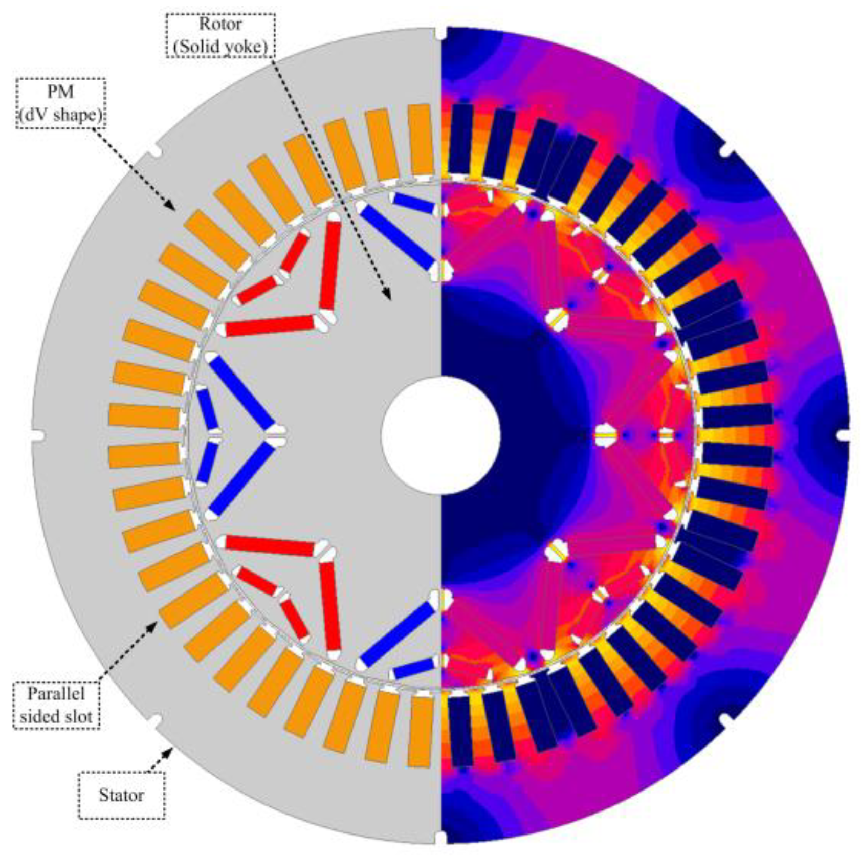
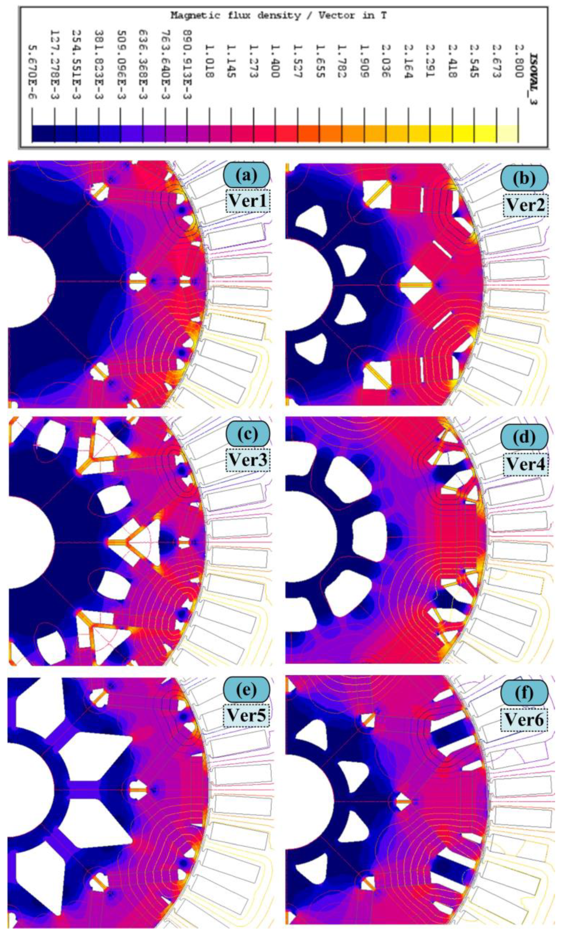
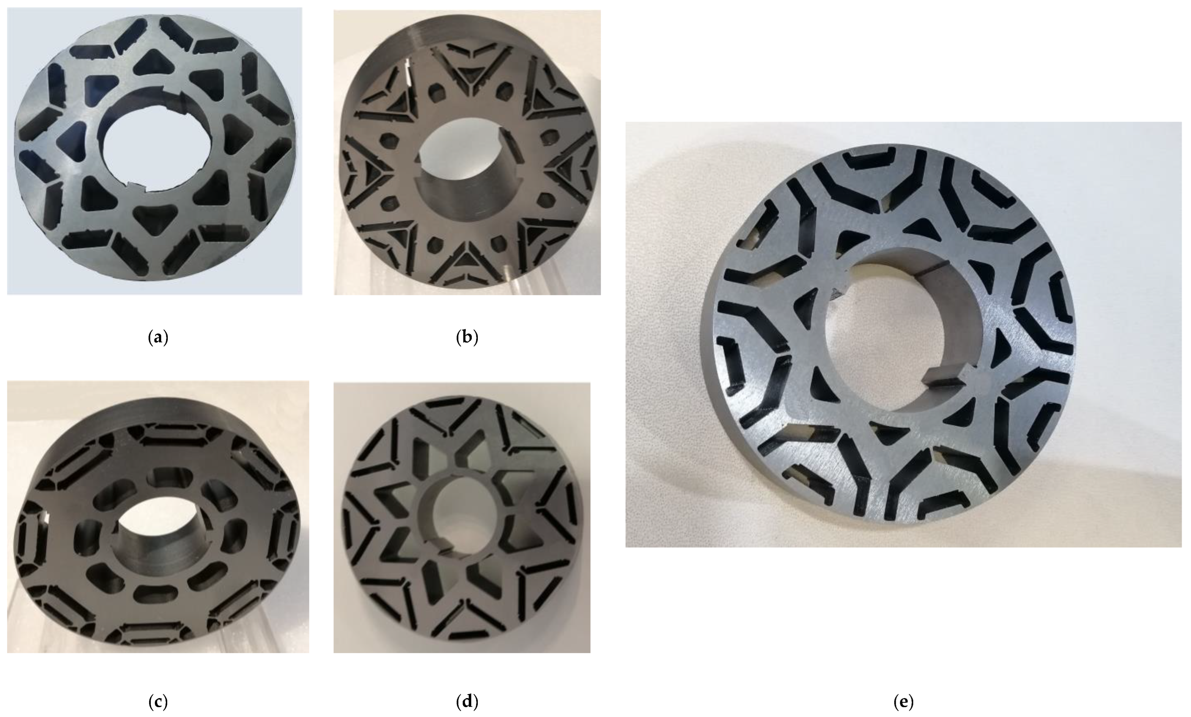
2. Rotor Barrier Shape Profiling
- Industry Relevance: SynRM technology has gained significant traction in recent years, particularly in industrial and automotive applications, due to its potential for high efficiency, reduced energy consumption, and sustainability. The drive towards more energy-efficient and environmentally friendly solutions intensifies, leading to a growing interest in optimizing SynRMs for various applications. This study aligns with this industry trend by addressing critical aspects of SynRM design.
- Challenges in Rotor Design: The rotor is a pivotal component of electric motors, significantly influencing their performance, efficiency, and cost-effectiveness. The rotor’s design intricacies, including material selection, dimensions, and barrier angles for q-magnets, present complex optimization challenges. By focusing on rotor design, this study aims to provide insights into how these design parameters impact motor performance and how they can be optimized for superior results.
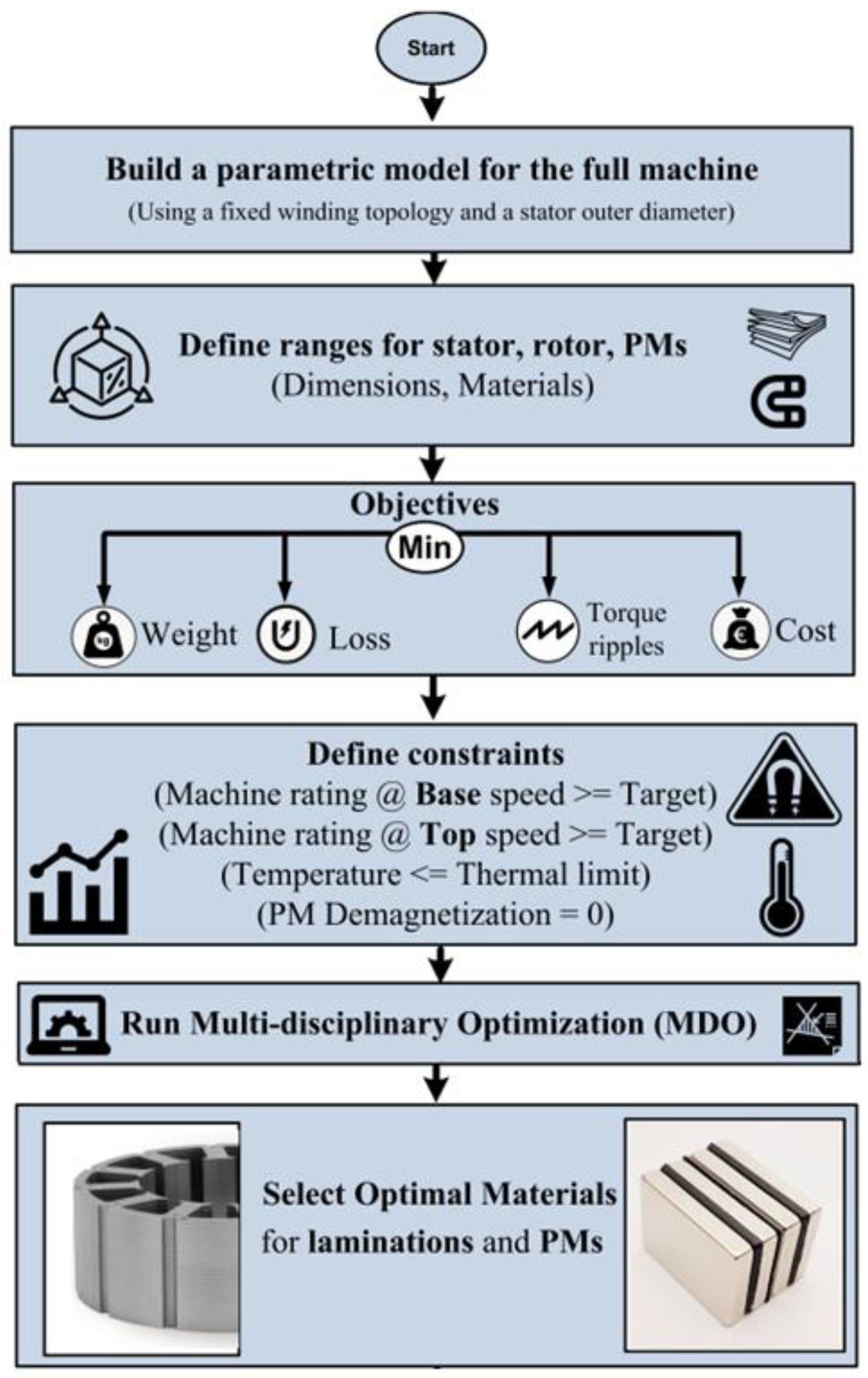
- Multidisciplinary Approach: A multidisciplinary design optimization (MDO) approach is adopted to address the complexities of rotor design. This approach enables the simultaneous consideration of multiple objectives, including minimizing losses, weight, cost, and torque ripples. By concentrating on SynRM rotor design, this study showcases the applicability and effectiveness of MDO in the context of electric machine design, which has broader implications for the field.
- Material Tradeoff Analysis: This study delves into the material tradeoffs within the rotor, considering various active electromagnetic components, such as laminations, conductors, and permanent magnets. This comprehensive analysis fills a gap in the literature, as prior studies have often focused on individual rotor components in isolation. The approach allows for a more holistic perspective on material selection.
3. Benchmarked Electrical Machine
3.1. Material Tradeoff
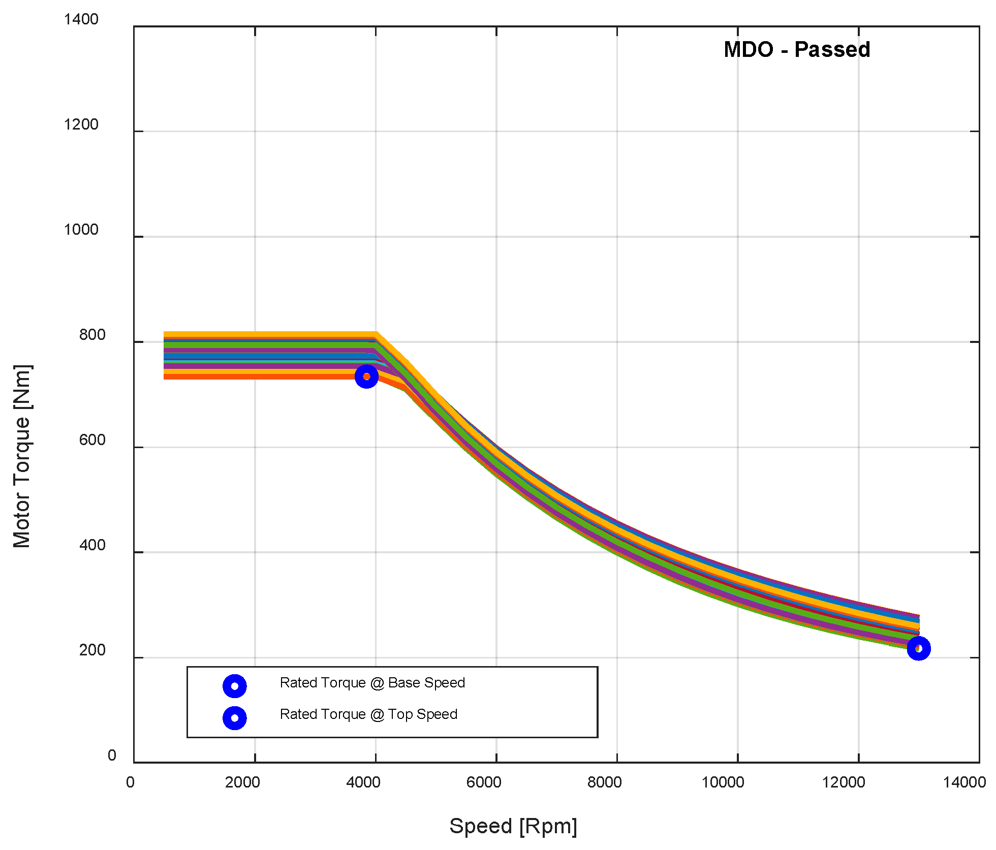
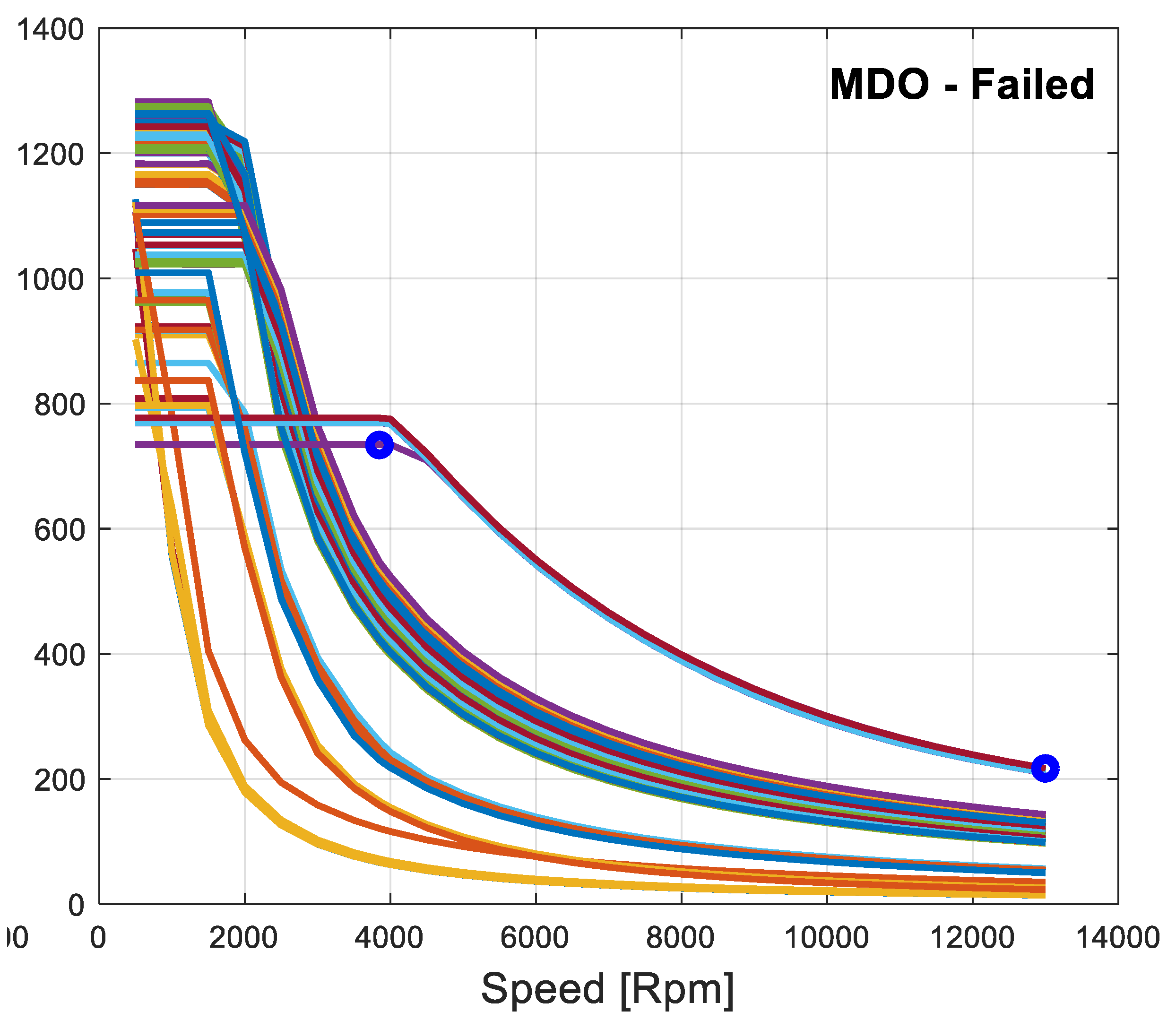
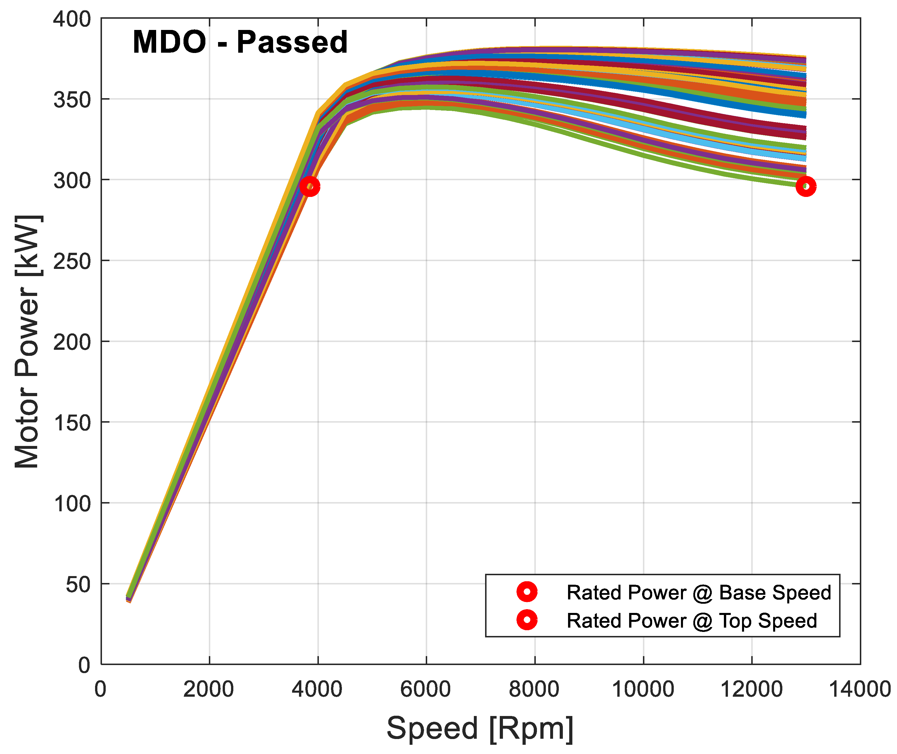
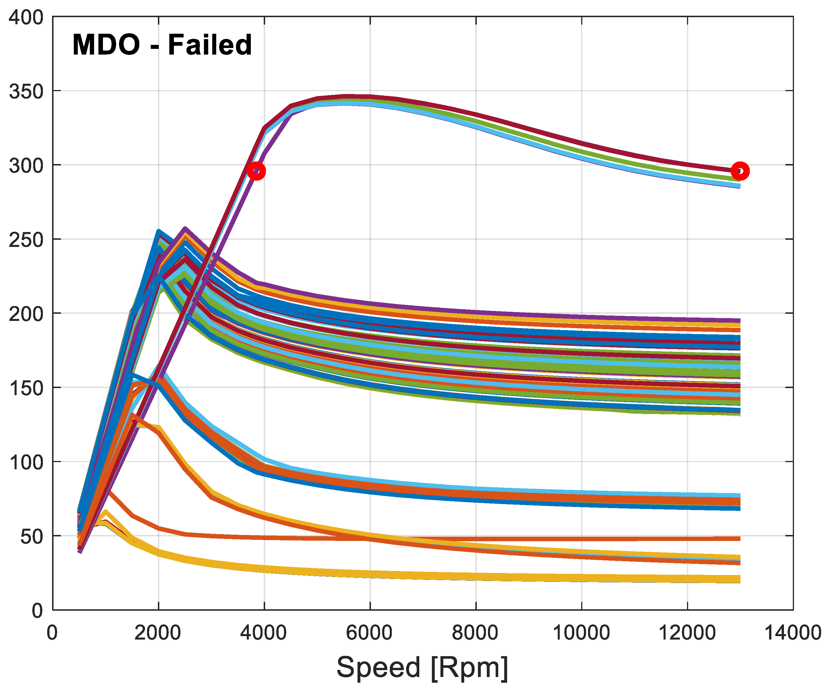
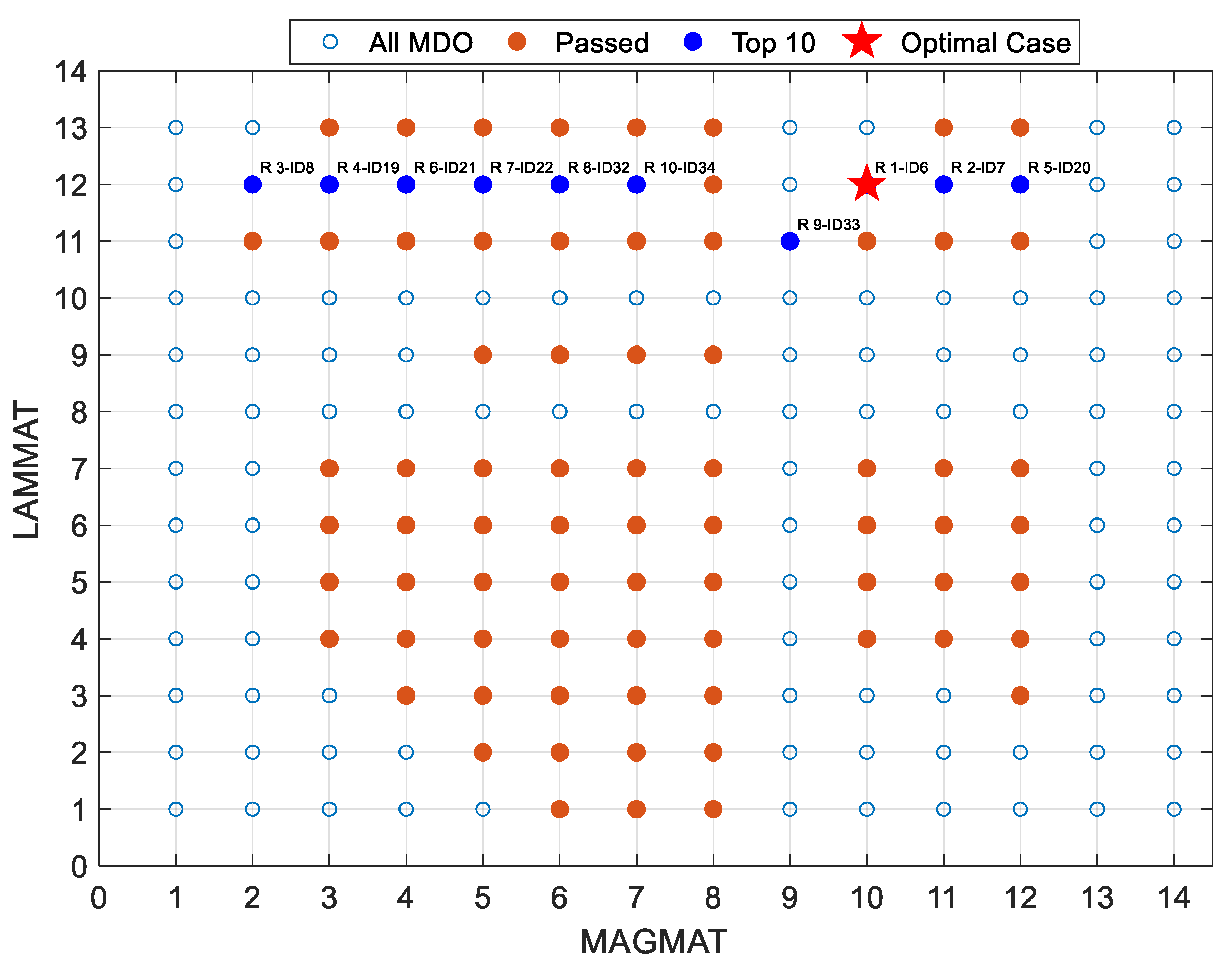
3.2. Full Design Optimization
- Comprehensive Evaluation: By waiting until the end of the optimization process to select the optimal design, we ensure that all generated design candidates have undergone a thorough evaluation against the defined objectives and constraints. This allows us to make an informed decision based on a comprehensive assessment of each candidate’s performance.
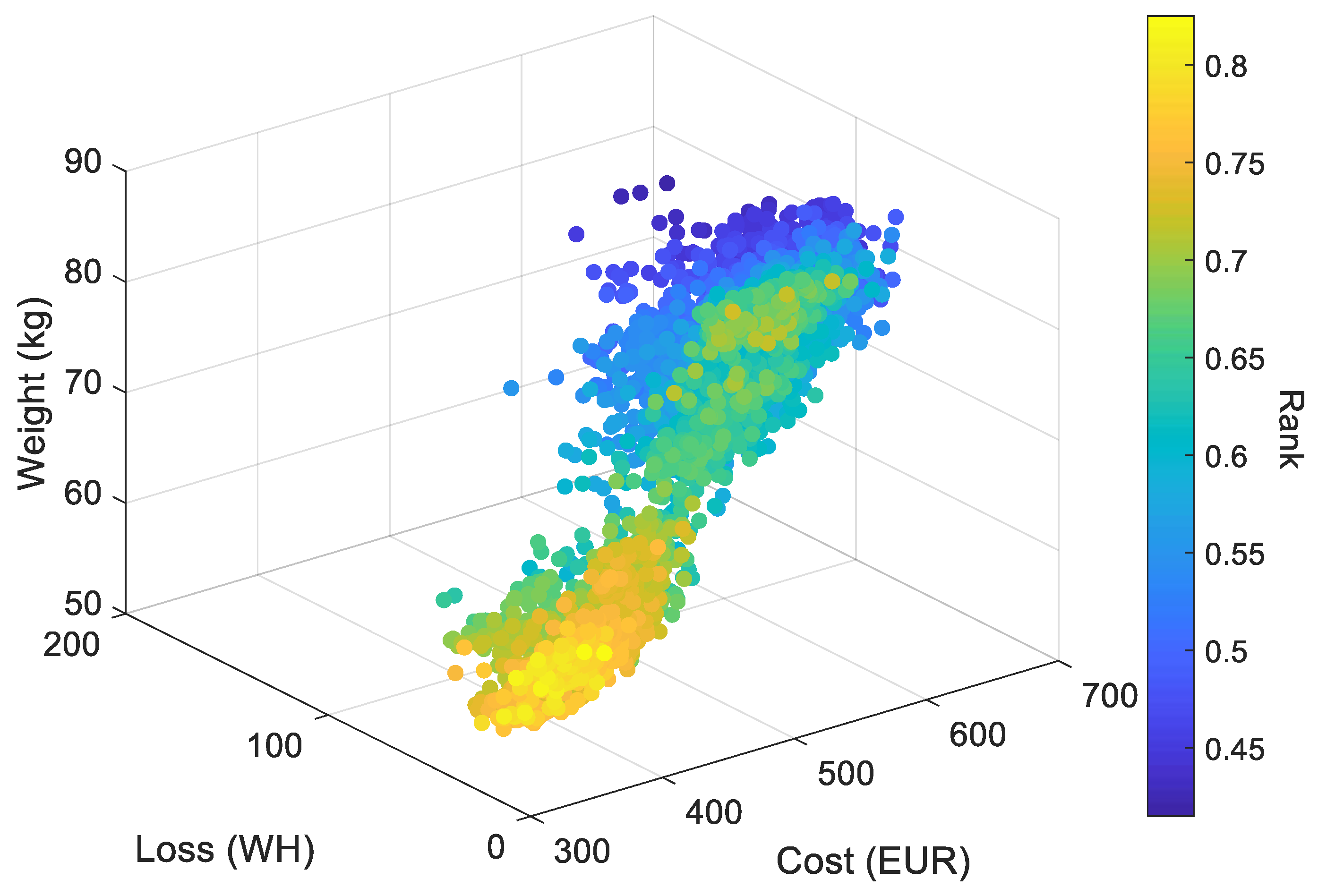
- Trade-off Analysis: Selecting the optimal design at this stage allows us to perform a detailed trade-off analysis. We can consider how each design candidate balances the competing objectives of minimizing losses, weight, torque ripples, and cost. This analysis ensures that the chosen design aligns with the overall goals of the project while considering potential trade-offs between different criteria.
- Practicality and Feasibility: It is essential to evaluate the practicality and feasibility of the optimal design in real-world applications. At this stage, we can assess factors such as manufacturability, maintenance requirements, and compatibility with existing systems. This evaluation ensures that the selected design is not only theoretically optimal but also viable for implementation.
- Consideration of External Factors: The selection of the optimal design allows us to take into account external factors that may influence the decision, such as market conditions, regulatory requirements, and customer preferences. This consideration ensures that the chosen design aligns with broader contextual factors that may impact its success.
- Resources and Documentation: Once the optimal design is selected, we can dedicate the necessary resources to thoroughly document and report on the chosen configuration. This documentation should include detailed specifications, performance characteristics, and any relevant design considerations. This step is essential for communicating the results of the optimization process effectively.
- Rank_i: This represents the calculated rank for the i-th design candidate, indicating how well it performs compared to others in the optimization process.
- Loss_min: This term represents the minimum loss among all design candidates, serving as a reference point for assessing the relative loss of the i-th candidate.
- Loss_i: Refers to the loss associated with the i-th design candidate.
- Weight_min: This term represents the minimum weight among all design candidates.
- Weight_i: Denotes the weight of the i-th design candidate.
- Cost_min: This term signifies the minimum cost among all design candidates.
- Cost_i: Represents the cost associated with the i-th design candidate.
- Ripple_min: This term signifies the minimum ripple among all design candidates, offering a benchmark for evaluating the relative ripple of the i-th candidate.
- Ripple_i: Denotes the ripple associated with the i-th design candidate
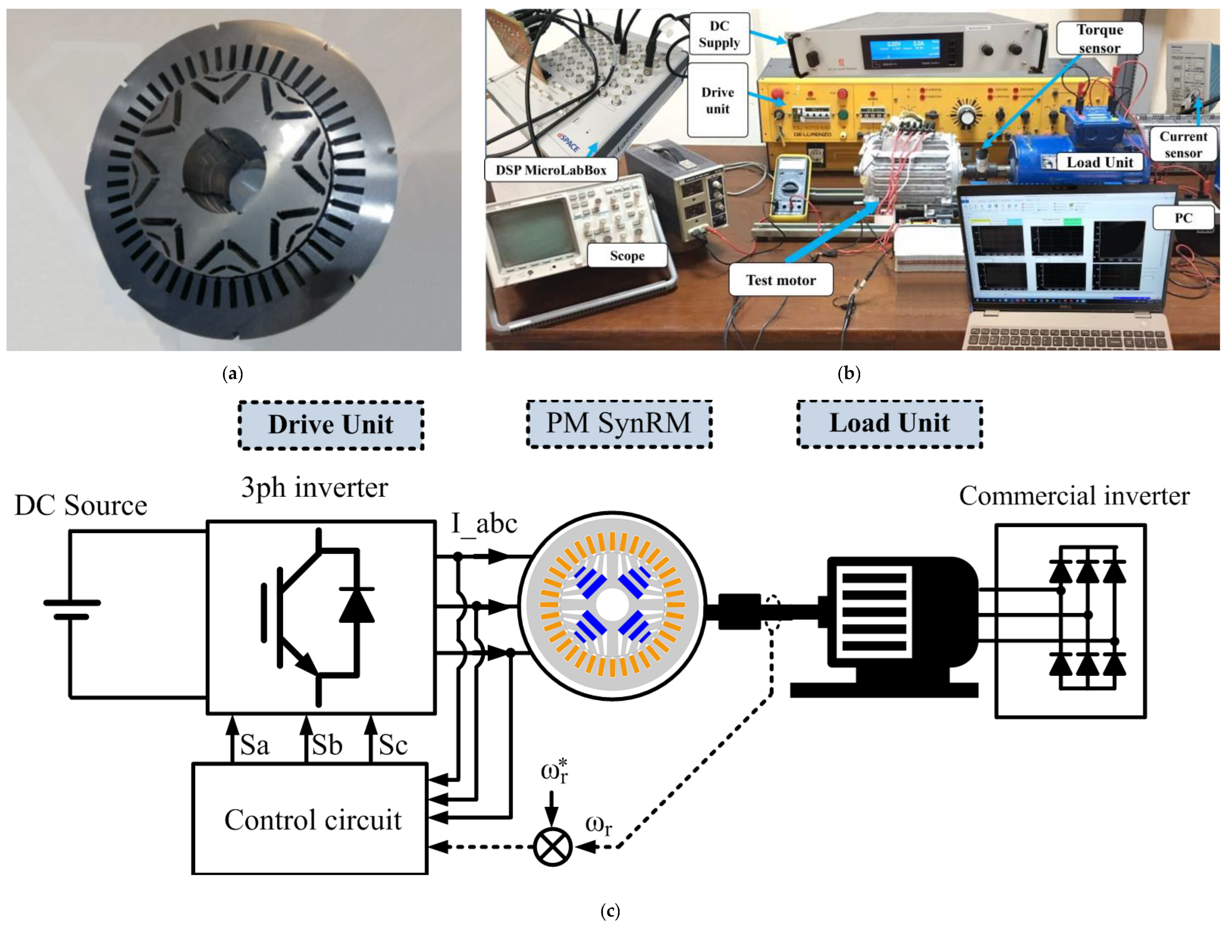
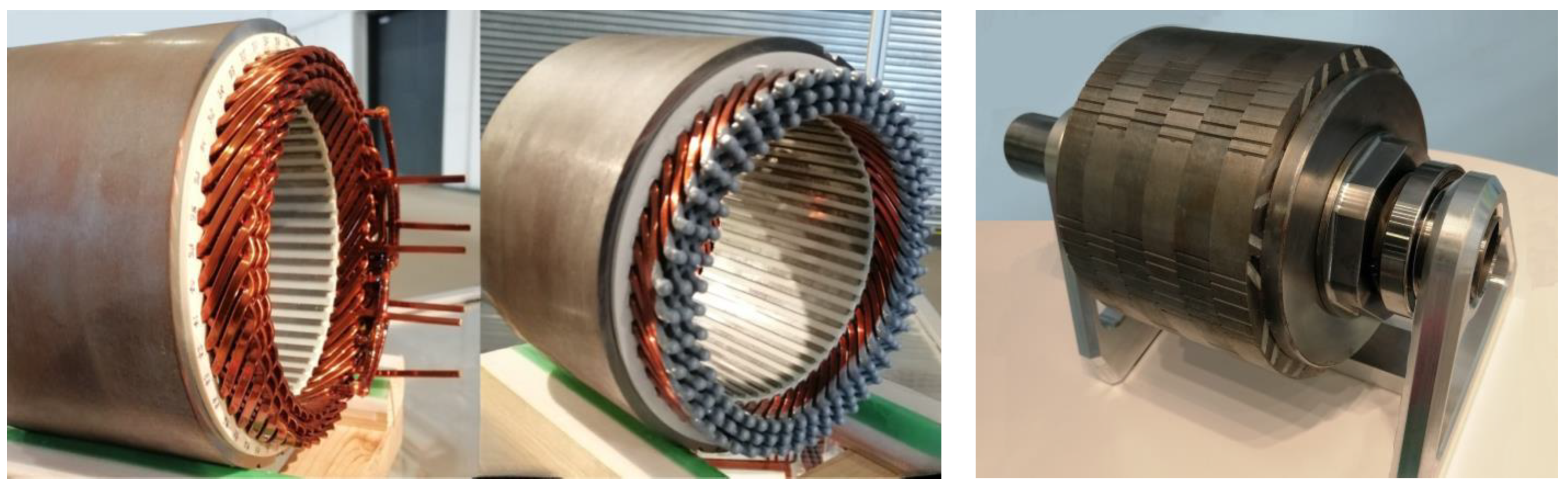
4. Prototyping and Measurement Results
5. Conclusions
Funding
Conflicts of Interest
References
- Jack, A.G. The Impact of New Materials on the Design of Electrical Machines. In Proceedings of the IEEE Colloquium on ‘The Impact of New Materials on Design’, IEEE, London, UK, 8 December 1995; Volume 1995, p. 1-1. [Google Scholar]
- Darius Gnanaraj, S.; Gundabattini, E.; Raja Singh, R. Materials for Lightweight Electric Motors—A Review. IOP Conf. Ser. Mater. Sci. Eng. 2020, 906, 012020. [Google Scholar] [CrossRef]
- Krings, A.; Cossale, M.; Tenconi, A.; Soulard, J.; Cavagnino, A.; Boglietti, A. Characteristics Comparison and Selection Guide for Magnetic Materials Used in Electrical Machines. In Proceedings of the 2015 IEEE International Electric Machines & Drives Conference (IEMDC), IEEE, Coeur d’Alene, ID, USA, 10–13 May 2015; pp. 1152–1157. [Google Scholar]
- Boehm, A.; Hahn, I. A New Approach in the Production of Electrical Motors Using Only Machining Processes. In Proceedings of the 2011 1st International Electric Drives Production Conference, IEEE, Nuremberg, Germany, 28–29 September 2011; pp. 78–83. [Google Scholar]
- Cossale, M.; Krings, A.; Soulard, J.; Boglietti, A.; Cavagnino, A. Practical Investigations on Cobalt–Iron Laminations for Electrical Machines. IEEE Trans. Ind. Appl. 2015, 51, 2933–2939. [Google Scholar] [CrossRef]
- Necula, D.; Vasile, N.; Stan, M.F. TThe Impact of the Electrical Machines on the Environment. In Proceedings of the 2013 8th International Symposium on Advanced Topics in Electrical Engineering (ATEE), IEEE, Bucharest, Romania, 23–25 May 2013; pp. 1–4. [Google Scholar]
- Abed, J.; Rayburg, S.; Rodwell, J.; Neave, M. A Review of the Performance and Benefits of Mass Timber as an Alternative to Concrete and Steel for Improving the Sustainability of Structures. Sustainability 2022, 14, 5570. [Google Scholar] [CrossRef]
- Xiao, X.; Muller, F.; Bavendiek, G.; Leuning, N.; Zhang, P.; Zou, J.; Hameyer, K. Modeling of Scalar Dependencies of Soft Magnetic Material Magnetization for Electrical Machine Finite-Element Simulation. IEEE Trans. Magn. 2020, 56, 1–4. [Google Scholar] [CrossRef]
- El-Refaie, A. Role of Advanced Materials in Electrical Machines. CES Trans. Electr. Mach. Syst. 2019, 3, 124–132. [Google Scholar] [CrossRef]
- Selema, A.; Ibrahim, M.N.; Sergeant, P. Electrical Machines Winding Technology: Latest Advancements For Transportation Electrification. Machines 2022, 10, 563. [Google Scholar] [CrossRef]
- Selema, A.; Ibrahim, M.N.; Sergeant, P. Mitigation of High-Frequency Eddy Current Losses in Hairpin Winding Machines. Machines 2022, 10, 328. [Google Scholar] [CrossRef]
- Selema, A.; Gulec, M.; Ibrahim, M.N.; Sprangers, R.; Sergeant, P. Selection of Magnet Wire Topologies With Reduced AC Losses for the Windings of Electric Drivetrains. IEEE Access 2022, 10, 121531–121546. [Google Scholar] [CrossRef]
- Nategh, S.; Krings, A.; Huang, Z.; Wallmark, O.; Leksell, M.; Lindenmo, M. Evaluation of Stator and Rotor Lamination Materials for Thermal Management of a PMaSRM. In Proceedings of the 2012 XXth International Conference on Electrical Machines, IEEE, Marseille, France, 2–5 September 2012; pp. 1309–1314. [Google Scholar]
- Selema, A.; Ibrahim, M.N.; Sergeant, P. Non-Destructive Electromagnetic Evaluation of Material Degradation Due to Steel Cutting in a Fully Stacked Electrical Machine. Energies 2022, 15, 7862. [Google Scholar] [CrossRef]
- Leupold, H.A.; Potenziani, E. Choice of Material in the Design of Permanent Magnet Flux Sources. IEEE Trans. Magn. 1993, 29, 3016–3018. [Google Scholar] [CrossRef]
- Liu, C.; Xu, Y.; Zou, J.; Yu, G.; Zhuo, L. Permanent Magnet Shape Optimization Method for PMSM Air Gap Flux Density Harmonics Reduction. CES Trans. Electr. Mach. Syst. 2021, 5, 284–290. [Google Scholar] [CrossRef]
- Magnetexpert Temperature Effects on Permanent Magnets. Available online: https://www.magnetexpert.com/technical-advice-for-every-application-magnet-expert-i685/temperature-effects-on-magnets-i683 (accessed on 26 February 2023).
- First4magnets How Does Temperature Affect Neodymium Magnets. Available online: https://www.first4magnets.com/tech-centre-i61/information-and-articles-i70/neodymium-magnet-information-i82/how-does-temperature-affect-neodymium-magnets-i91 (accessed on 1 March 2023).


| Version | Design | Av Torque | Torque Ripples | PM Demag. | Rotor Losses | BMax | %Saturation Area * |
|---|---|---|---|---|---|---|---|
| Ver1 (Ref) | dV | 725 N.m | 4.6% | 0.1% | 1.00 p.u. | 2.31 T | 38% |
| Ver2 | sV | 723 N.m | 2.9% | 1.8% | 1.09 p.u. | 2.73 T | 56% |
| Ver3 | mdV | 733 N.m | 7.2% | 3.3% | 1.02 p.u. | 2.46 T | 53% |
| Ver4 | dU | 730 N.m | 5.3% | 6.2% | 1.10 p.u. | 2.80 T | 67% |
| Ver5 | DL | 741 N.m | 2.1% | 5.4% | 0.98 p.u. | 2.25 T | 32% |
| Ver6 | UV | 759 N.m | 3.8% | 0.2% | 0.95 p.u. | 2.22 T | 21% |
| Input Parameters Of the Full Machine | |||||
|---|---|---|---|---|---|
| Parameter | Symbol | Range | Parameter | Symbol | Range |
| Stator outer diameter | fixed | d-Barrier width | ) | ||
| Rotor outer diameter | q-Barrier width | ) | |||
| Machine stack length | d-Magnet width | ||||
| Aspect Ratio | q-Magnet width | ||||
| Split Ratio | d-Magnet ratio | ||||
| Airgap length | Gap | fixed | q-Magnet ratio | ||
| Yoke height | ) | Barrier angle | Indicated in F4 | ||
| Slot height | ) | Lamination Materials | LM | 1–12 (discrete) | |
| Slot width | ) | Magnet Materials | MM | 1–13 (discrete) | |
| Index | Lamination Material (LM) | PM Material (MM) | Index | Lamination Material (LM) | PM Material (MM) |
|---|---|---|---|---|---|
| 1 | NO20 | G38UH | 8 | B27AV1400 | G54UH |
| 2 | NO27 | G40UH | 9 | B35A250 | N38UH |
| 3 | NO30 | G42UH | 10 | HIPERM_49 | N40UH |
| 4 | M235_35A | G45UH | 11 | HYPOCORE_25 | N42UH |
| 5 | M250_35A | G48UH | 12 | 20JNEH | N45UH |
| 6 | M270_35A | G50UH | 13 | VACOFLUX | MAGFINE |
| 7 | M300_35A | G52UH | 14 | - | TDK_FB |
| Max. Working Temperature for Each PM Grade | |||
|---|---|---|---|
| N50/N52 | 60 °C | SH | 150 °C |
| STANDARD | 80 °C | UH | 180 °C |
| M | 100 °C | EH | 200 °C |
| H | 120 °C | AH | 230 °C |
| Parameter | Value | Parameter | Value |
|---|---|---|---|
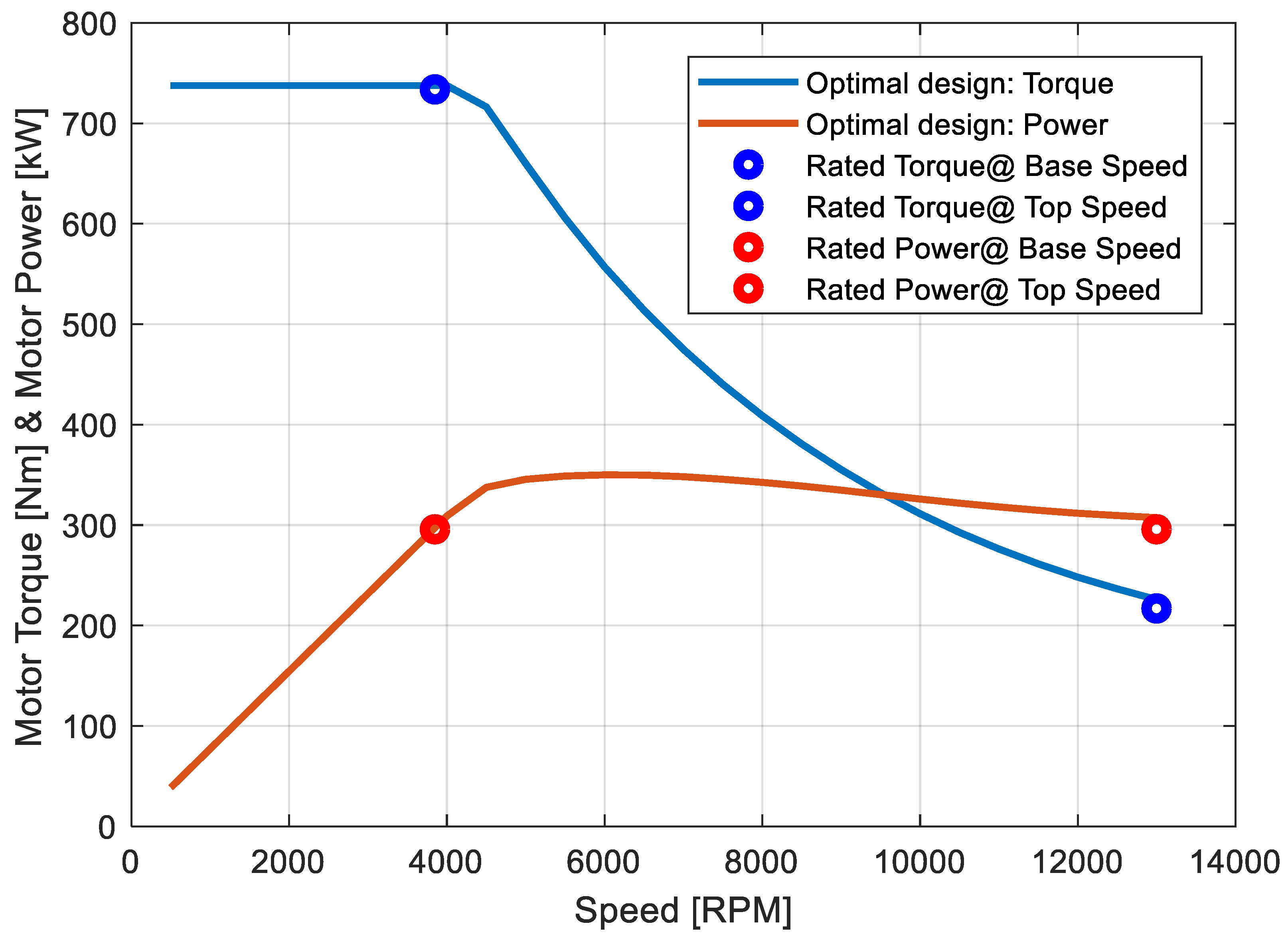
| Number of slots | 48 | Motor Power | 307.4 kW |
| Stack length | 181.5 mm | Base Speed | 3850 RPM |
| Rotor outer diameter | 188.25 mm | Torque @ Base Speed | 737.6 N.m |
| Airgap length | 0.8 mm | Torque @ Top Speed | 225.8 N.m |
| Slot width (ws) | 6.42 mm | Rated MMF per slot | 5547 AT |
| Yoke height (Hy) | 16.1 mm | Number of armature phases | 3 |
| q-magnet width (wMQ) | 27.6 mm | Number of rotor poles | 8 |
| q-magnet height (HMQ) | 5.98 mm | Number of Turns per Slot | 8 |
| d-magnet width (wMD) | 14.9 mm | Lamination material | 20JNEH1200 |
| d-magnet height (HMD) | 8 mm | PM material | N40UH |
| Version | Rotor Weight | Power Losses @ Base Speed | Peak Torque | Torque Density (*) N.m/kg | |||
|---|---|---|---|---|---|---|---|
| Ver1 (Ref) | 29.61 kg | 9.52 kW | 716 N.m | 24.2 | |||
| Ver2 | 27.14 kg (−8.3%) | 10.37 kW (+9%) | 714 N.m (−0.3%) | 26.3 (8.6%) | |||
| Ver3 | 27.58 kg (−6.8%) | 9.71 kW (+2%) | 724 N.m (+1.1%) | 26.3 (8.6%) | |||
| Ver4 | 26.22 kg (−11.4%) | 10.48 kW (+10%) | 721 N.m (+0.7%) | 27.5 (13.6%) | |||
| Ver5 | 25.97 kg (−12.3%) | 9.32 kW (−2%) | 733 N.m (+2.4%) | 28.2 (16.5%) | |||
| Ver6 | 26.36 kg (−11.0%) | 9.04 kW (−5%) | 748 N.m (+4.5%) | 28.4 (17.4%) | |||
| * Peak Torque/Rotor weight | |||||||
| Measured | Extrapolation based on measurements | FE Simulation | Calculated based on (*) | ||||
Disclaimer/Publisher’s Note: The statements, opinions and data contained in all publications are solely those of the individual author(s) and contributor(s) and not of MDPI and/or the editor(s). MDPI and/or the editor(s) disclaim responsibility for any injury to people or property resulting from any ideas, methods, instructions or products referred to in the content. |
© 2023 by the author. Licensee MDPI, Basel, Switzerland. This article is an open access article distributed under the terms and conditions of the Creative Commons Attribution (CC BY) license (https://creativecommons.org/licenses/by/4.0/).
Share and Cite
Selema, A. Material Tradeoff of Rotor Architecture for Lightweight Low-Loss Cost-Effective Sustainable Electric Drivetrains. Sustainability 2023, 15, 14413. https://doi.org/10.3390/su151914413
Selema A. Material Tradeoff of Rotor Architecture for Lightweight Low-Loss Cost-Effective Sustainable Electric Drivetrains. Sustainability. 2023; 15(19):14413. https://doi.org/10.3390/su151914413
Chicago/Turabian StyleSelema, Ahmed. 2023. "Material Tradeoff of Rotor Architecture for Lightweight Low-Loss Cost-Effective Sustainable Electric Drivetrains" Sustainability 15, no. 19: 14413. https://doi.org/10.3390/su151914413
APA StyleSelema, A. (2023). Material Tradeoff of Rotor Architecture for Lightweight Low-Loss Cost-Effective Sustainable Electric Drivetrains. Sustainability, 15(19), 14413. https://doi.org/10.3390/su151914413