Article

A Novel Biomimetic Lung-Shaped Flow Field for All-Vanadium Redox Flow Battery

1
School of Ecology and Environment, Beijing Technology and Business University, Beijing 100048, China
2
Key Laboratory of Cleaner Production and Integrated Resource Utilization of China National Light Industry, Beijing Technology and Business University, Beijing 100048, China
3
College of Mechanical and Electrical Engineering, Beijing University of Chemical Technology, Beijing 100029, China
*
Author to whom correspondence should be addressed.
Sustainability 2023, 15(18), 13613; https://doi.org/10.3390/su151813613
Submission received: 5 August 2023 / Revised: 30 August 2023 / Accepted: 31 August 2023 / Published: 12 September 2023
(This article belongs to the Special Issue Stability and Optimization of Flow Battery Performance)

Abstract

:
The all-vanadium redox flow battery (VRFB) was regarded as one of the most potential technologies for large-scale energy storage due to its environmentally friendliness, safety and design flexibility. The flow field design and mass transfer performance in the porous electrodes were some of the main factors to influence the battery performance. A novel biomimetic lung-shaped flow field was designed, and the battery performance was compared with the serpentine flow field by numerical simulation analysis. The results showed that the charging voltage of the VRFB was reduced by about 5.34% when SOC = 0.9 compared with the serpentine flow field. On the other hand, the discharging voltage was promoted by about 9.77% when SOC = 0.1 compared with the serpentine flow field. The battery performance of the VRFB is obviously due to the enhancement of the mass transfer performance. The uniformity factor was promoted by 35.6% by the lung-shaped flow field when SOC = 0.1, which can reduce the polarization loss. The average concentration of the active ions was increased by about 18% by the lung-shaped biomimetic flow field, which was of significance to the electrochemical reaction. The design of the lung-shaped flow field can contribute to the application of the VRFB.

1. Introduction

Climate change has become a serious issue due to the excessive emission of carbon dioxide. In order to achieve China’s commitment to peak carbon emissions by 2030, the vigorous development of renewable energy and the improvement of the energy structure are of great significance. However, renewable energy sources such as wind and solar energy have disadvantages of intermittency, instability, and lack of controllability, and are influenced greatly by environmental conditions such as time and climate [1,2]. Therefore, the development of large-scale energy storage technology is crucial for the advancement of renewable energy. Compared to lithium-ion batteries, redox flow batteries are safer and more suitable for large-scale energy storage infrastructure. Among the commercially viable redox flow batteries, the all-vanadium redox flow battery stands out owing to its higher energy density [3,4].
The performance of the all-vanadium redox flow battery (VRFB) is influenced by various factors such as the porous electrodes, membranes, and flow fields. Therefore, it is essential to study and identify the main influencing factors on the performance of the VRFB. The numerical calculation is an effective method to investigate the performance and the mass transfer behaviors for the VRFB. Through the numerical simulations, not only can the battery’s performance be predicted, but also the distribution of multiple physical fields within the porous electrode can be obtained, providing data that may not be obtained through experiments. This method has made significant contributions to improving the performance of the VRFB [5]. Many researchers have conducted numerous simulation studies on VRFB using numerical simulation methods. Skyllas-Kazacos et al. [6] simulated the concentration distribution of different vanadium ions during the charge–discharge process using numerical simulation and predicted the capacity loss caused by the accumulation and decay of different vanadium ions in the half-battery. Pugach et al. [7] proposed a 0-D dynamic mathematical model of the all-vanadium redox flow battery based on the principles of charge and mass transfer conservation, based on which the diffusion, migration, and convection can be simulated accurately and the impact of these phenomena on capacity decay can be investigated. Knehr et al. [8] proposed a two-dimensional transient isothermal numerical model for the all-vanadium redox flow battery to predict ion transport and capacity loss during battery operation. The model combines the effects of convection, diffusion, and migration on ion transport, as well as the water transfer phenomena, based on which the variation of electrolyte volume and the side reactions can be investigated. Ma et al. [9] established a three-dimensional steady-state isothermal half-battery model for the negative electrode of the all-vanadium redox flow battery based on the principles of charge, mass, and momentum conservation, based on which the distribution of velocity, concentration, overpotential, and current density were investigated. The results showed that concentration, overpotential, and current density were greatly influenced by the velocity distribution of the electrolyte, and the lower velocities could result in higher overpotential. Kyeongmin et al. [10] developed a three-dimensional transient non-isothermal mathematical model for the all-vanadium redox flow battery, based on which the various heating mechanisms, including reversible and irreversible heat generation from redox reactions, were analyzed. Wang and Cho [11] established a three-dimensional transient non-isothermal mathematical model for the all-vanadium redox flow battery based on the mass and energy conservation equations and electrochemical reaction kinetics. The model predicted flow rates, concentrations, temperatures, and local reaction rates. The results indicated a significant correlation between the time constants of local reaction rates and temperature variations. Ma et al. [12] investigated the influences of the pore size distribution and porosity on the quinone flow battery performance based on a two-dimensional porous electrode model. Their findings suggested that the specific surface area affected the current density directly.
The flow fields of the redox flow batteries have a significant impact on the distribution of active ions inside the porous electrodes, which can affect the battery performance. A scientifically reasonable flow field structure can increase the flow rate of the electrolyte, resulting in a more uniform distribution of the electrolyte within the battery. Higher flow velocity and uniform distribution can weaken the local concentration polarization significantly, which can promote the battery’s performance and enhance the battery’s service life. In recent years, many researchers have conducted deep studies on the flow field structure for vanadium redox flow batteries. Zhang et al. [13] established a two-dimensional mathematical model of an all-vanadium redox flow battery and found that as the rising of the parallel serpentine channels number, the pumping power decreased. Aaron et al. [14] designed a zero-gap flow field structure with a serpentine flow field, which ensured good contact between battery components and reduced the distance of charge transfer. Moreover, the presence of the serpentine flow field facilitated more uniform electrolyte distribution and enhanced mass transfer in the battery. Kumar and Jayanti [15] investigated the effects of the flow field on the all-vanadium redox flow battery performance and pointed out that the round-trip energy efficiency of about 80% could be obtained at the highest flow rate with the serpentine flow field. Ravendra and Sreenivas [16] studied the effects of channel dimensions on the vanadium redox flow battery performance, which suggested increasing channel width and decreasing rib width. Darling and Perry [17] reported the influence of electrode and channel configurations on flow battery performance, which showed that the interdigitated flow field was well-suited for large batteries. Kumar and Jayanti [18] investigated the effects of electrode intrusion on pressure drop and electrochemical performance, which showed that the electrode intrusion into the flow channel could result in the resistance increasing to electrolyte flow through the electrode.
The biomimetic flow fields were common for the fuel cells, which were not popular in the redox flow batteries. As the structure of redox flow batteries was very similar to that of the fuel cells, inspired by the fuel cells’ biomimetic flow fields, the biomimetic flow fields can be used for the redox flow batteries. Kloess et al. [19] designed two biomimetic flow field structures based on the leaf and lung leaf while referring to serpentine flow field and interdigitated flow field. By comparing the two biomimetic flow fields with the serpentine flow field and interdigitated flow field, it was found that the battery with a biomimetic flow field has a lower pressure drop at the inlet and outlet compared to the traditional flow field, and it has higher output power and efficiency and better performance in water and heat management. Jessica [20] designed two biomimetic flow field structures based on Murray’s law of branches in plants and animals, respectively, known as the biomimetic plant vein flow field and the biomimetic animal vein flow field. The two biomimetic flow fields were compared with the triple serpentine flow field. It was found that the biomimetic flow field structure exhibited lower inlet and outlet pressure drop, with a more uniform distribution. Additionally, it demonstrated stronger water and heat management capabilities, resulting in better battery performance. Gutierrez et al. [21] designed a bifurcated biomimetic flow field based on a branching system, investigating three different levels of bifurcation in the biomimetic flow field structures. A comparison was made between the biomimetic flow field, serpentine flow field, and parallel flow field, revealing that the biomimetic flow field had a lower pressure drop and a more uniform flow distribution, while also displaying superior water and heat management capabilities. Furthermore, within the three biomimetic flow field structures, the higher the level of bifurcation, the better the battery performance.
Considering the application of biomimetic flow fields in the field of fuel cells, this paper proposes a novel biomimetic lung-shaped flow field that can enhance the multi-component transport inside the redox flow battery electrodes. With the application of biomimetic flow fields in redox flow batteries, a three-dimensional steady-state numerical model of an all-vanadium redox flow battery with a lung-shaped biomimetic flow field was established and compared with the traditional serpentine flow field. The study investigates the influence of the lung-shaped biomimetic flow field structure on the mass transfer capacity and battery performance. In order to explore the effects of electrolyte flow rate and initial concentration on battery performance, the electrolyte flow rate and initial concentration are varied based on the lung-shaped biomimetic flow field, and the mass transfer capacity and battery performance of the vanadium battery are studied under different electrolyte flow rates and initial concentrations.

2. Model

Figure 1 shows the schematic of the all-vanadium redox flow battery structure, based on which the conversion between electrical energy and chemical energy can be achieved. During the operation of the all-vanadium redox flow battery, the electrolyte was pumped into the porous electrodes through the flow field. The ion exchange membrane was located between the positive and negative electrodes, which can almost isolate all ions in the positive and negative electrolytes except for protons [22]. The generated electric current was collected and conducted by the outermost current collector plates [23].
During the charge and discharge process of an all-vanadium redox flow battery, the electrochemical reactions occurring at the positive and negative electrodes inside the battery were presented as follows:
Positive electrode:
VO 2 + + H 2 O e discharge charge VO 2 + + 2 H +
Negative electrode:
V 3 + + e discharge charge V 2 +
The hydromechanics and reaction processes in the porous electrodes were too complex to be described. The reasonable assumptions and simplifications were made and presented as follows:
(1)
The electrolyte was treated as an incompressible fluid.
(2)
The mass transport process in the porous electrode was assumed to be a dilute species transport.
(3)
The electrodes, electrolyte, and ion exchange membrane were regarded to be homogeneous and isotropic.
(4)
The state of charge (SOC) of the electrolyte is introduced to define the concentrations of reactants and products in the electrolyte at any given moment, simplifying the dynamic model into a steady-state model.
(5)
The ion exchange membrane only allowed the protons to pass through.
(6)
The intrusion of the felt electrode into the channel was ignored.

2.1. Governing Equations

2.1.1. Transport in the Flow Field

The mass conservation equation in the flow field is presented:
N i = 0
where N i is the molar flux of species i (with i representing V2+, V3+, VO2+, V O 2 + , H+, H S O 4 ).

2.1.2. Transport in the Electrodes

As the electrochemical reactions only took place in the porous electrodes, the mass continuity equation is described as follows:
ρ v = 0
where ρ is the electrolyte density.
The Brinkman equation was used to predict the momentum conservation in the porous electrodes:
ρ ε ( ( v ) v ε ) = [ p + μ ε ( v + ( v ) T ) 2 μ 3 ε ( v ) ] μ K v
where ε is the porosity and K is the permeability.
In the process of charging and discharging, the mass conservation of each species i can be presented as follows:
N i = S i
where Si is the source term of species i. Ni is the molar flux of species i.
Taking the diffusion, convection and migration of the charged species into consideration, the Nernst–Plank equation was used to modify the molar flux Ni:
N i = ε 3 / 2 D i c i Z i ε 3 / 2 D i R T F c i Φ e l + v c i
where Di and Zi are the diffusion coefficient and the valence, respectively. F is the Faraday’s constant.

2.1.3. Transport in the Membrane

The vanadium ion crossover of the membrane is ignored and only the H+ can pass. The molar flux N H + can be presented as follows:
N H + = σ m F Φ m
where σ m and Φ m are the conductivity and electronic potential of the membrane.
( k Φ μ H 2 O F c H + Φ m k p μ H 2 O p ) = 0
where k Φ is the electrokinetic permeability. kp and p are the hydraulic permeability of water and hydraulic pressure in the membrane.
As for the simplification, not all the equations are presented in this paper, which can be found in [1].

2.2. Boundary Condition

All the above equations should be restricted by the boundary conditions. For the inlet of the flow field, the flow velocity and the concentration of the electrolyte are given. The outlet of the flow field and the atmospheric pressure were selected, and the concentration gradient of outlet ions was set to zero. The other boundaries were regulated by the Neumann condition. The negative edge was the grounded boundary condition and the average current density was applied at the positive edge.

2.3. Performance Parameters

To evaluate the performance of the battery under two different flow field structures, the charge and discharge voltages of the battery were calculated using the following formula:
E ch = ( E eq , p E eq , n ) + ( η p + η n ) + I avg A R b a
E dis = ( E eq , p E eq , n ) ( η p + η n ) I avg A R b a
where A is the surface area of the electrode. Iavg is the average current density, and R is the internal resistance of VRFBs.
In order to assess the uniformity of electrolyte concentration distribution in the porous electrode, the quantitative analysis was employed, and the uniformity factor was calculated using the following formula:
U = 1 1 C i , ave 1 V ( C i C i . ave ) 2 d V
where Ci,ave is the average concentration of ions i.

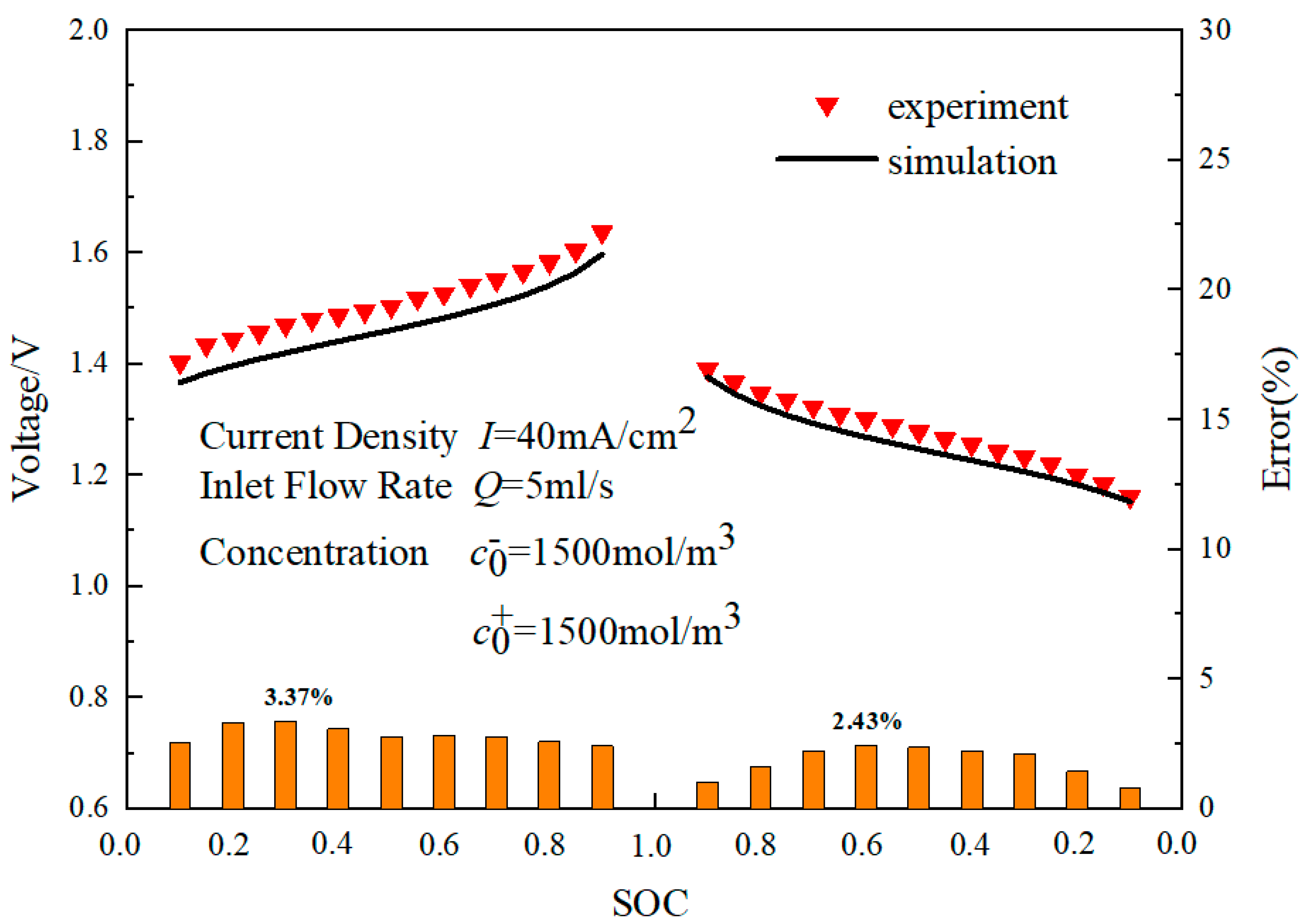
2.4. Numerical Details and Model Validation

All the above models and equations were set up using COMSOL software 5.5, in which the secondary current distribution, transport of dilute species and Brinkman equation were applied. The kinetic, electrochemical, geometric and operational parameters applied in the model are given in Table 1. In order to validate the reliability of the numerical model, the simulated data were compared with the results from reference [24]. The operating conditions were set the same as those in the experiments, and the comparison between the simulation results and experimental data is shown in Figure 2. It can be observed that in both the charging and discharging processes, the results of the numerical model exhibited a good agreement with the experimental results, indicating that the numerical model can predict the charging and discharging processes effectively. The maximum error between the simulated data and experimental data during the charging process was 3.37%, while during the discharging process, the maximum error was 2.43%. The small differences between the simulated and experimental data may be attributed to the neglect of ion transport through the ion exchange membrane and secondary reactions that occur in the experiments but are not considered in the numerical simulation.

3. Results and Discussion

A biomimetic lung-shaped flow field was designed in this paper, which was compared with the serpentine flow field. The biomimetic lung-shaped flow field and the serpentine flow field are shown in Figure 3a,b. The cross-section of the biomimetic lung-shaped flow field and the serpentine flow field were 3 mm × 3 mm, and the total length was the same. The cross-sectional area of the electrodes and ion exchange membrane were both 120 × 120 mm, with an electrode thickness of 4 mm and an ion exchange membrane thickness of 0.2 mm. The charge–discharge voltage, overpotential, uniformity factor, average concentration, pressure drop, power, and efficiency of the biomimetic lung-shaped flow field and the serpentine flow field were investigated in this section, which can clarify the mechanism of the biomimetic lung-shaped flow field on multi-component transport within porous electrodes.

3.1. Battery Performance

The charging–discharging voltage was an important factor for evaluating the performance of redox flow batteries. Therefore, the charging and discharging voltage of the lung-shaped flow field and the traditional serpentine flow field were obtained based on the numerical model established in this paper. Figure 4 shows the variations of the charging and discharging voltage for the lung-shaped biomimetic flow field and the traditional serpentine flow field. The charging voltage gradually increased as the SOC varies from 0.1 to 0.9, while the discharging voltage gradually decreased as the SOC varies from 0.9 to 0.1. In the whole charging process, the charging voltage of the lung-shaped flow field was lower than that of the traditional serpentine flow field. During the entire discharge process, the lung-shaped flow field generated a higher discharge voltage compared to the traditional serpentine flow field. The discharge voltage of the lung-shaped flow field was 9.77% than that of the serpentine flow field. The lung-shaped flow field needed a 5.34% lower charging voltage compared with the serpentine flow field. Therefore, the battery performance of the lung-shaped flow field was much superior to that of the traditional serpentine flow field.
The overpotential of the redox flow battery can affect the discharging voltage, so the overpotential of two flow fields was investigated in this paper. Figure 5 showed the variation of the positive and negative electrode overpotentials during the vanadium redox flow battery discharging process for both flow field configurations, which illustrated that the absolute values of the overpotentials generated by the lung-shaped biomimetic flow field were much lower than those in the traditional serpentine flow field. This indicated that the lung-shaped biomimetic flow field structure exhibited smaller differences between the working potential and equilibrium potential of the vanadium redox flow battery, which illustrated that the lung-shaped biomimetic flow field structure can achieve better battery performance compared to the traditional serpentine flow field.

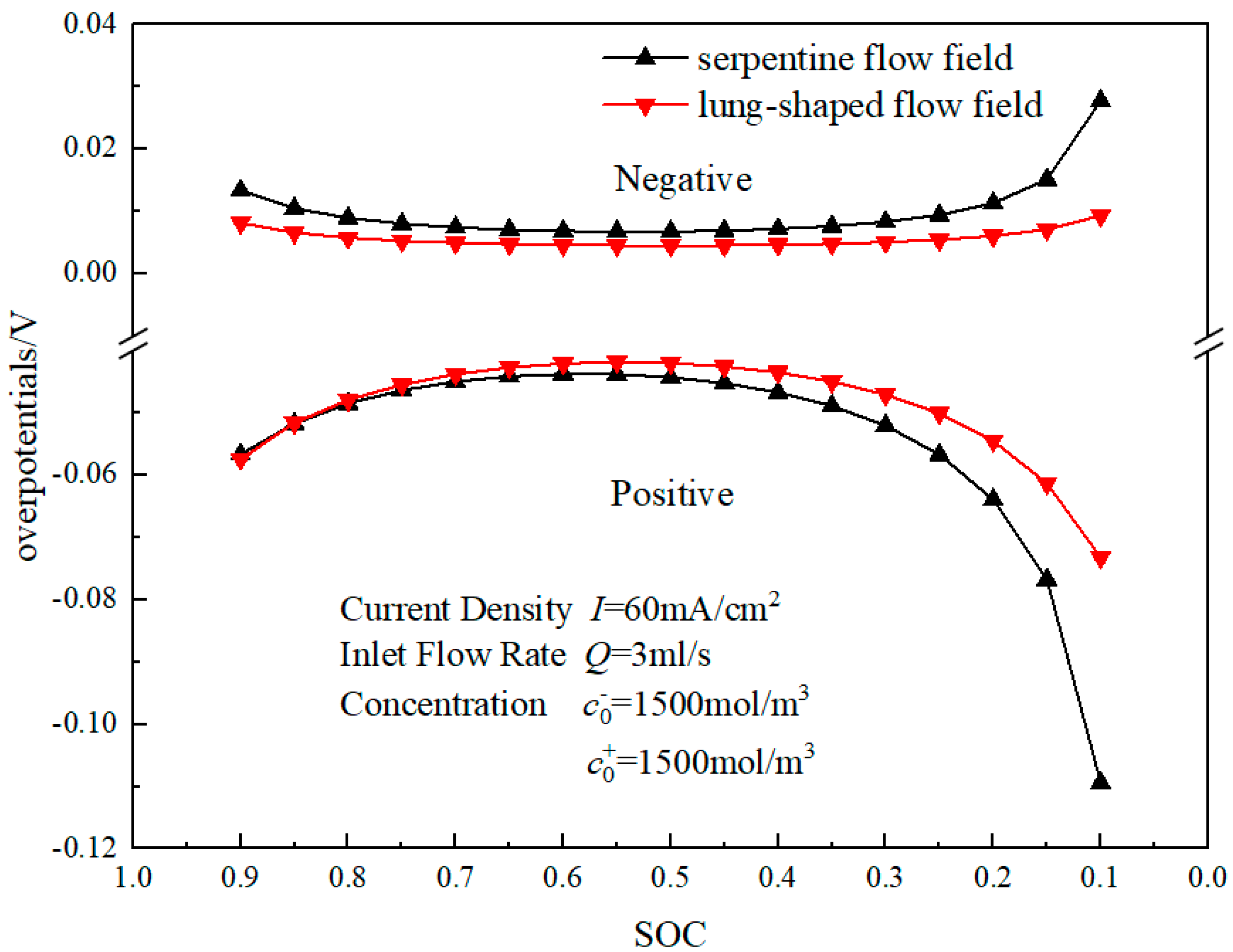
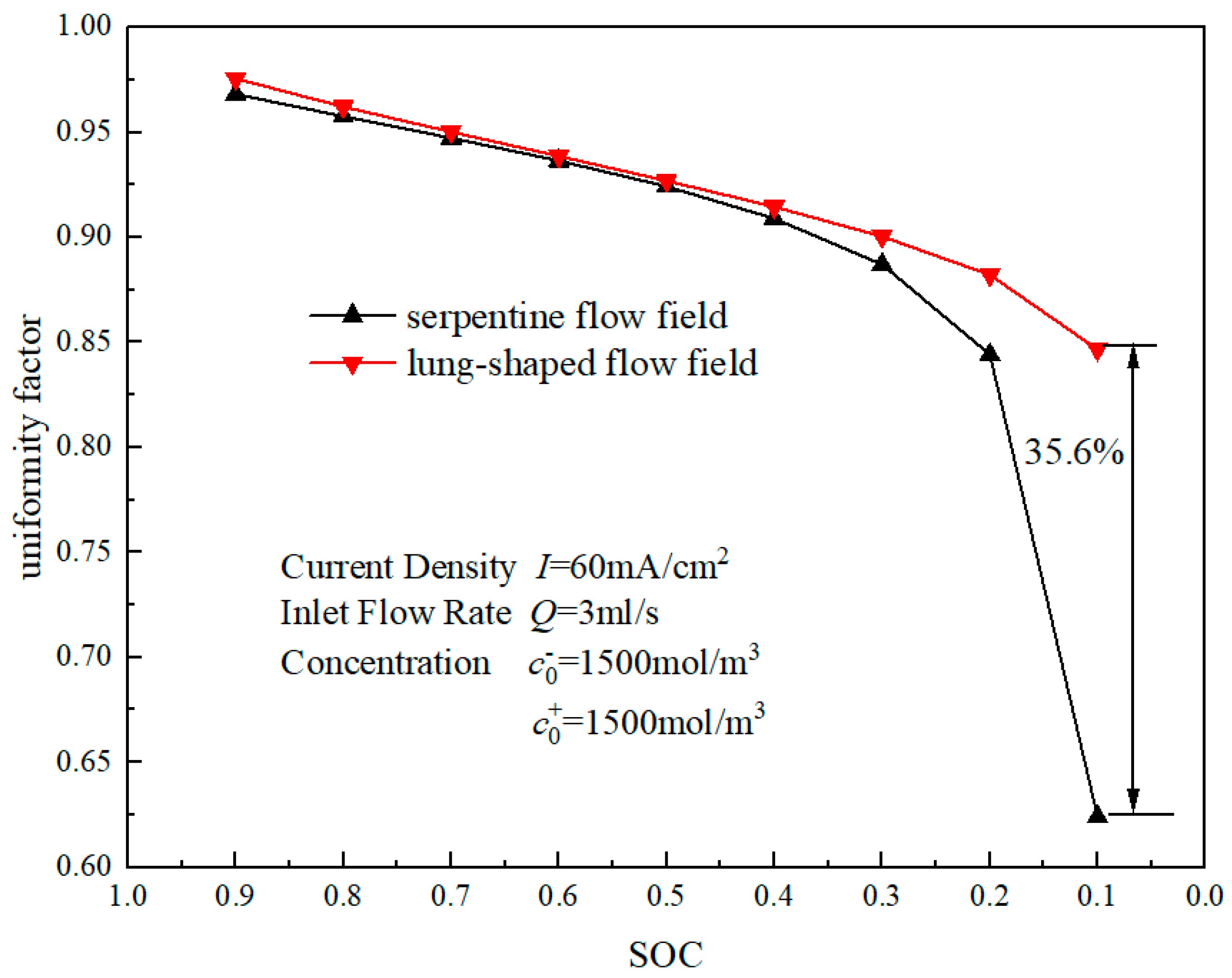
3.2. Mass Transfer Performance

The battery performance and polarization loss were related to the concentration distribution of the active ions. Therefore, the concentration distribution uniformity was investigated in this paper. Figure 6 shows the variations of the uniformity factor during the discharge process for the lung-shaped biomimetic flow field and the traditional serpentine flow field, which indicates that the uniformity factors gradually decrease as the battery discharges for the two flow fields. The uniformity factors of the lung-shaped biomimetic flow field were higher than those of the traditional serpentine flow field. When SOC was 0.1, the uniformity factor of the lung-shaped biomimetic flow field was 35.6% higher than that of the traditional serpentine flow field. This indicated that the lung-shaped biomimetic flow field could enhance the uniform distribution of the active ions.
The electrochemical reaction was influenced by the concentration of the active ions, which was mainly influenced by the multi-species transport characteristics inside the porous electrode of the redox flow battery. In order to study the distribution of active ions within the porous electrode quantitatively, the electrode was divided into four equal parts, as shown in Figure 7. The concentration of V2+ was selected as the research object. The contours of the V2+ concentration on the 1/4 L, 1/2 L, and 3/4 L cut planes were shown in Figure 8, which illustrated that the concentration in the lung-shaped biomimetic flow field was obviously higher than in the traditional serpentine flow field for each cut plane. This indicated that the lung-shaped biomimetic flow field could enhance the mass transfer of active ions from the flow field to the electrode. Additionally, the concentration distribution in the lung-shaped biomimetic flow field was more uniform compared to the traditional serpentine flow field.
Quantitative analysis was of significance for the investigation. The average concentration values of V2+ when SOC = 0.2 were presented in Figure 9, and it can be observed that on all three cut planes, the average active ion concentration of the lung-shaped biomimetic flow field was higher than that in the traditional serpentine flow field. Specifically, at the 3/4 L cross-section, the average concentration of the lung-shaped biomimetic flow field was 18% higher than that of the traditional serpentine flow field. The above results indicated that the lung-shaped biomimetic flow field structure can accelerate the mass transfer from the flow field to the membrane and promote the uniformity of the active ion distribution inside the porous electrode.

3.3. Output Characteristic

In order to further study the impact mechanism of the lung-shaped biomimetic flow field on the output performance, the pressure drop, output power and efficiency were investigated in this paper. The pressure drops of the lung-shaped biomimetic flow field and the traditional serpentine flow field are shown in Figure 10, which illustrates that the pressure drop of the lung-shaped biomimetic flow field was much lower than that of the traditional serpentine flow field. It can be observed that the loss of the lung-shaped biomimetic flow field was much lower, which was of significance for the battery efficiency.
Figure 11a shows the variations of the net discharge power with the different SOCs for the lung-shaped biomimetic flow field and the traditional serpentine flow field, which indicates that during the discharge process, the net discharge power decreased gradually with SOC ranging from 0.9 to 0.1. Moreover, the lung-shaped biomimetic flow field structure achieved much higher net discharge power compared to the traditional serlow field in the whole discharge process. Figure 11b presents the variations of the power-based efficiency during the discharge process for the lung-shaped biomimetic flow field and the traditional serpentine flow field, which illustrates that the power-based efficiency of the lung-shaped biomimetic flow field was much higher than that of the traditional serpentine flow field. This indicates that the lung-shaped biomimetic flow field not only exhibited better mass transfer behaviors but also had a higher battery performance.

4. Conclusions

In this paper, a novel biomimetic lung-shaped flow field was designed, which is compared with the common serpentine flow field based on a 3-D numerical model. The results showed that the discharging voltage of the lung-shaped flow field was 9.77% higher than that of the serpentine flow field when SOC = 0.1. The lung-shaped flow field needed a 5.34% lower charging voltage compared with the serpentine flow field when SOC = 0.9. The uniformity factor of the lung-shaped biomimetic flow field was 35.6% higher than that of the traditional serpentine flow field when SOC = 0.1. The power-based efficiency and the net output power of the lung-shaped biomimetic flow field were much higher than that of the traditional serpentine flow field due to the lower pressure drop of the lung-shaped biomimetic flow field. At the 3/4 L cross-section, the average concentration of the lung-shaped biomimetic flow field was 18% higher than that of the traditional serpentine flow field, which illustrated that lung-shaped biomimetic flow field can enhance the mass transfer in the porous electrode. The design of the lung-shaped biomimetic flow field can enhance the mass transfer and promote battery performance, which can contribute to the application of the VRFB.

Author Contributions

L.Z.: Writing; F.C.: Funding acquisition, Writing. All authors have read and agreed to the published version of the manuscript.

Funding

The financial support for this research from the Open Research Fund Program of Key Laboratory of Cleaner Production and Integrated Resource Utilization of China National Light Industry (Grant No. CP2022YB06) and the Beijing Natural Science Foundation (3232025) are gratefully acknowledged.

Data Availability Statement

All the data were gained from the numerical model.

Conflicts of Interest

The authors declare that there are no competing financial interests.

References

  1. Liu, X.; Zhang, P.F.; Yang, J.L.; Li, J.; Chu, F.M. Effect of variable cross-section electrode on the battery performance of all-vanadium redox flow battery. Int. J. Heat Mass Transf. 2023, 215, 124382. [Google Scholar] [CrossRef]
  2. Ning, Y.; Fu, K.; Ke, Z.; Yunlong, Z.; Wen-Feng, L. A strategy for CO2 capture and utilization towards methanol production at industrial scale: An integrated highly efficient process based on multi-criteria assessment. Energy Convers. Manag. 2023, 293, 117516. [Google Scholar]
  3. Chuanyu, S.; Enrico, N.; Angeloclaudio, N.; Gioele, P.; Keti, V.; Thomas, A.Z.; Laura, M.; Chiara, G.; Vito, D.N. An efficient barrier toward vanadium crossover in redox flow batteries: The bilayer [Nafion/(WO3)x] hybrid inorganic-organic membrane. Electrochim. Acta 2021, 378, 138133. [Google Scholar]
  4. Huan, Z.; Yi, T.; Xu-Dong, L.; Chuan-Yu, S.; Na, C. Polarization Effects of a Rayon and Polyacrylonitrile Based Graphite Felt for Iron-Chromium Redox Flow Batteries. ChemElectroChem 2019, 6, 3175–3188. [Google Scholar]
  5. Jungmyung, K.; Heesung, P. Mass transfer in flow batteries characterized by comparison of electrical potentials according to regions of porous electrodes. J. Energy Storage 2022, 55, 105556. [Google Scholar]
  6. Skyllas-Kazacos, M.; Goh, L. Modeling of vanadium ion diffusion across the ion exchange membrane in the vanadium redox battery. J. Membr. Sci. 2012, 399–400, 43–48. [Google Scholar] [CrossRef]
  7. Pugach, M.; Kondratenko, M.; Briola, S.; Bischi, A. Zero dimensional dynamic model of vanadium redox flow battery cell incorporating all modes of vanadium ions crossover. Appl. Energy 2018, 226, 560–569. [Google Scholar] [CrossRef]
  8. Knehr, K.W.; Agar, E.; Dennison, C.R.; Kalidindi, A.R.; Kumbur, E.C. A transient vanadium flow battery model incorporating vanadium crossover and water transport through the membrane. J. Electrochem. Soc. 2012, 159, 1446–1459. [Google Scholar] [CrossRef]
  9. Ma, X.K.; Zhang, H.M.; Xing, F. A three-dimensional model for negative half cell of the vanadium redox flow battery. Electrochim. Acta 2011, 58, 238–246. [Google Scholar] [CrossRef]
  10. Kyeongmin, O.; Haneul, Y.; Johan, K.; Seongyeon, W.; Hyunchul, J. Three-dimensional, transient, nonisothermal model of all-vanadium redox flow batteries. Energy 2015, 81, 3–14. [Google Scholar]
  11. Wang, Y.; Cho, S.C. Analysis and three-dimensional modeling of vanadium flow batteries. J. Electrochem. Soc. 2014, 161, 1200–1212. [Google Scholar] [CrossRef]
  12. Ma, C.; Li, X.; Lin, L.; Chen, L.; Wang, M.; Zhou, J.J.J.o.E.S. A two-dimensional porous electrode model for designing pore structure in a quinone-based flow cell. J. Energy Storage 2018, 18, 16–25. [Google Scholar] [CrossRef]
  13. Zhang, B.W.; Lei, Y.; Bai, B.F.; Zhao, T.S. A two-dimensional model for the design of flow fields in vanadium redox flow batteries. Int. J. Heat Mass Transf. 2019, 135, 460–469. [Google Scholar] [CrossRef]
  14. Aaron, D.S.; Liu, Q.; Tang, Z.; Grim, G.M.; Papandrew, A.B.; Turhan, A.; Zawodzinski, T.A.; Mench, M.M. Dramatic performance gains in vanadium redox flow batteries through modified cell architecture. J. Power Sources 2012, 206, 450–453. [Google Scholar] [CrossRef]
  15. Kumar, S.; Jayanti, S. Effect of flow field on the performance of an all-vanadium redox flow battery. J. Power Sources 2016, 307, 782–787. [Google Scholar] [CrossRef]
  16. Ravendra, G.; Sreenivas, J. Effect of channel dimensions of serpentine flow fields on the performance of a vanadium redox flow battery. J. Energy Storage 2019, 23, 148–158. [Google Scholar]
  17. Darling, R.M.; Perry, M.L. The Influence of Electrode and Channel Configurations on Flow Battery Performance. J. Electrochem. Soc. 2014, 161, 1381–1387. [Google Scholar] [CrossRef]
  18. Kumar, S.; Jayanti, S. Effect of electrode intrusion on pressure drop and electrochemical performance of an all-vanadium redox flow battery. J. Power Sources 2017, 360, 548–558. [Google Scholar] [CrossRef]
  19. Kloess, J.P.; Wang, X.; Liu, J.; Shi, Z.Y.; Guessous, L. Investigation of bio-inspired flow channel designs for bipolar plates in proton exchange membrane fuel cells. J. Power Sources 2009, 188, 132–140. [Google Scholar] [CrossRef]
  20. Jessica, M.C. Biomimetic Design Applied to the Redesign of a PEM Fuel Cell Flow Field. Master’s Thesis, University of Toronto, Toronto, ON, Canada, 2010. [Google Scholar]
  21. Gutierrez, L.D.; Hernandez-Guerrero, A.; Alvarado, B.R.; Perez-Raya, I.; Alatorre-Ordaz, A. Performance analysis of a proton exchange membrane fuel cell using tree-shaped designs for flow distribution. Int. J. Hydrogen Energy 2013, 38, 14750–14763. [Google Scholar] [CrossRef]
  22. Jinchao, L.; Jun, L.; Wenheng, H.; Wenjie, X.; Jun, L.; Huan, L.; Yaping, Z. Novel branched sulfonated polyimide membrane with remarkable vanadium permeability resistance and proton selectivity for vanadium redox flow battery application. Int. J. Hydrogen Energy 2022, 47, 8883–8891. [Google Scholar]
  23. Xu, Z.Y.; Jing, M.H.; Fan, X.Z.; Liu, J.G.; Yan, C.W. Advanced dual-gradient carbon nanofibers/graphite felt composite electrode for the next-generation vanadium flow battery. J. Mater. Sci. Technol. 2022, 136, 32–42. [Google Scholar] [CrossRef]
  24. Xu, Q.; Zhao, T.S.; Leung, P.J.A.e. Numerical investigations of flow field designs for vanadium redox flow batteries. Appl. Energy 2013, 105, 47–56. [Google Scholar] [CrossRef]
  25. Wang, Q.; Qu, Z.G.; Jiang, Z.Y.; Yang, W.W. Numerical study on vanadium redox flow battery performance with nonuniformly compressed electrode and serpentine flow field. Appl. Energy 2018, 220, 106–116. [Google Scholar] [CrossRef]
  26. Yang, W.W.; He, Y.L.; Li, Y.S. Performance modeling of a vanadium redox flow battery during discharging. Electrochim. Acta 2015, 155, 279–287. [Google Scholar] [CrossRef]
  27. Lu, M.Y.; Yang, W.W.; Bai, X.S.; Deng, Y.M.; He, Y.L. Performance improvement of a vanadium redox flow battery with asymmetric electrode designs. Electrochim. Acta 2019, 319, 210–226. [Google Scholar] [CrossRef]
  28. Yang, W.W.; Bai, X.S.; Zhang, W.Y.; Lu, M.Y.; Xu, Q. Numerical examination of the performance of a vanadium redox flow battery under variable operating strategies. J. Power Sources 2020, 457, 228002. [Google Scholar] [CrossRef]
  29. Lu, M.Y.; Yang, W.W.; Deng, Y.M.; Li, W.Z.; Xu, Q.; He, Y.L. Mitigating capacity decay and improving charge-discharge performance of a vanadium redox flow battery with asymmetric operating conditions. Electrochim. Acta 2019, 309, 283–299. [Google Scholar] [CrossRef]
  30. Yue, M.; Zheng, Q.; Xing, F.; Zhang, H.M.; Li, X.F.; Ma, X.K. Flow field design and optimization of high power density vanadium flow batteries: A novel trapezoid flow battery. AIChE J. 2018, 64, 782–795. [Google Scholar] [CrossRef]
  31. Chu, F.M.; Xiao, G.Z.; Xia, L.X.; Yang, Y.; Yang, G.A.; Tan, Z.A. Analysis of battery performance and mass transfer behavior for organic redox flow battery with different flow fields. J. Electrochem. Soc. 2022, 169, 70529. [Google Scholar] [CrossRef]
Figure 1. Schematic of VRFB structure.
Sustainability 15 13613 g001
Figure 2. Comparisons between numerical solutions and experimental data.
Sustainability 15 13613 g002
Figure 3. (a) Schematic of serpentine flow field. (b) Schematic of lung-shaped flow field.
Sustainability 15 13613 g003
Figure 4. Variations of the charging and discharging voltage for the lung-shaped biomimetic flow field and the traditional serpentine flow field.
Sustainability 15 13613 g004
Figure 5. Variations of overpotentials for the lung-shaped biomimetic flow field and the traditional serpentine flow field.
Sustainability 15 13613 g005
Figure 6. Variations of the uniformity factor during the discharge process.
Sustainability 15 13613 g006
Figure 7. Three-dimensional diagram of the different electrode sections.
Sustainability 15 13613 g007
Figure 8. Concentration contours on the (a,d) 1/4 L, (b,e) 1/2 L, and (c,f) 3/4 L cut plane.
Sustainability 15 13613 g008
Figure 9. Average concentration values of V2+ when SOC = 0.2.
Sustainability 15 13613 g009
Figure 10. Pressure drops of lung-shaped flow field and serpentine flow field.
Sustainability 15 13613 g010
Figure 11. (a) Variations of the net output power with the different SOCs. (b) Variations of the power-based efficiency during discharge process.
Sustainability 15 13613 g011
Table 1. Kinetic and electrochemistry parameters used in the simulation.
ParameterSymbolValueSource
Specific surface area(m−1)a2.5 × 105Ref. [24]
Diffusion coefficient of V2+(m2/s)DV2+2.4 × 10−10Ref. [25]
Diffusion coefficient of V3+(m2/s)DV3+2.4 × 10−10Ref. [25]
Diffusion coefficient of VO2+DVO2+3.9 × 10⁻¹⁰Ref. [25]
Diffusion coefficient of V O 2 + D V O 2 + 3.9 × 10⁻¹⁰Ref. [25]
Diffusion coefficient of SO4(m2/s)DSO42−1.065 × 10−9Ref. [25]
Diffusion coefficient of HSO4(m2/s)D H S O 4 1.33 × 10⁻⁹Ref. [25]
Diffusion coefficient of H+(m2/s)DH+3.5 × 10−9Ref. [25]
Operating temperature (K)T300 KRef. [24]
Electrode conductivity(S/m)σs1000Ref. [24]
Membrane conductivity(S/m)σm10Ref. [24]
Anodic transfer coefficientsα+0.5Assumed
Cathodic transfer coefficientα0.5Assumed
Rate constant, negative reaction(m/s)kneg1.7 × 10−7Ref. [26]
Rate constant, positive reaction(m/s)kpos6.8 × 10−7Ref. [25]
Standard potential of negative reaction(V)E0,neg−0.255Ref. [27]
Standard potential of positive reaction(V)E0,pos1.004Ref. [28]
Fiber diameter of the electrode (μm)df17.6Ref. [29]
Kozeny-Carmen CoefficientKck4.89Ref. [30]
Pump efficiencyφ0.9Ref. [31]
Disclaimer/Publisher’s Note: The statements, opinions and data contained in all publications are solely those of the individual author(s) and contributor(s) and not of MDPI and/or the editor(s). MDPI and/or the editor(s) disclaim responsibility for any injury to people or property resulting from any ideas, methods, instructions or products referred to in the content.

