Article

Numerical Investigations of Tribological Characteristics of Biomimetic-Textured Surfaces

1
College of Mechanical and Vehicle Engineering, Chongqing University, Chongqing 400044, China
2
School of Mechanical Engineering and Automation, Chongqing Industry Polytechnic College, Chongqing 401120, China
3
School of Mechanical and Power Engineering, Chongqing University of Science and Technology, Chongqing 401331, China
*
Authors to whom correspondence should be addressed.
Sustainability 2023, 15(17), 13054; https://doi.org/10.3390/su151713054
Submission received: 12 July 2023 / Revised: 11 August 2023 / Accepted: 28 August 2023 / Published: 30 August 2023
(This article belongs to the Special Issue Sustainable Development of Intelligent Rail Transit)

Abstract

:
Rail transportation has dramatically improved travel convenience, but it has also led to environmental pollution and energy consumption issues. These challenges can be partially addressed by reducing friction loss in the mechanical transmission of rail systems. This paper examines the tribological properties of bionic-textured surfaces inspired by snake- and sharkskin. This study focuses on generating bionic textured surfaces with randomly distributed peaks through numerical simulation and connecting them to a transient Reynolds equation and friction fatigue model. The bionic surface wear lubrication model considers the lubricating film’s thickness and contact pressure obtained from the GT model. The results reveal that the existence of a bionic texture can reduce the friction coefficient and wear amount on the contact surface. The findings of this study not only offer a potential solution for reducing energy consumption and emissions in intelligent rail transit systems but also hold promise for providing further insights into the numerical simulation of bionic weaving and the investigation of tribological characteristics.

1. Introduction

Rail transport is more environmentally friendly and sustainable than other modes of transportation [1]. However, with the widespread use of rail transport, its energy consumption base has also become huge, and carbon neutrality and carbon peak policies have placed higher energy-saving and emission requirements on it [2]. Therefore, reducing the friction and wear of mechanical transmission components during train operation is conducive to energy saving and environmental protection. Train bearings are essential in rail transport, as they bear the weight of most of the vehicle and the high-speed rotation of the wheels. Friction loss is the primary energy loss of train bearings, so reducing the friction and wear between the bearing rollers and the raceways can reduce energy consumption and improve reliability [3].
Similarly, biological evolution also develops in a direction conducive to survival and reduces unnecessary energy consumption. For example, bird feathers and bodies can reduce air resistance, and fish skin and scales can reduce water resistance. Inspired by this, many researchers have introduced bionic surfaces into machinery [4].
Many designed biomimetic-textured surfaces have been experimentally verified to have the ability to improve the tribological properties of surfaces. Greiner et al. [5] developed a biomimetic scale-like surface texture inspired by the scales on the skin of snakes and certain lizards and through tribological pin-on-disk testing, found that the surface texture reduced dry sliding-friction forces by more than 40%. In addition, inspired by sharkskin, Guo et al. [6] and Li et al. [7] studied the physical properties of biomimetic-textured sharkskin, showing that the sharkskin has a wear-reducing effect. Rong et al. [8] processed a micro–nano-structure array of biomimetic fish scales onto the surface of magnesium aluminum alloy, and resistance was reduced by about 50%. Domel et al. [9] designed a shark tooth structure into a wing to improve its aerodynamic effect. Ballesteros et al. [10] printed a snakeskin texture with nylon fiber using 3D printing technology and conducted friction and wear tests with 304 stainless steel. They found that the friction coefficient of textured samples was always low. Tsipenyuk et al. [11] analyzed the contact pads on animals and obtained a bionic hexagonal texture structure. Li et al. [12] described the tribological properties of the four-leaf clover texture. In addition to single-layer textures, there are multiple layers of textures in biological systems in nature. Consequently, many scholars have studied multi-scale biomimetic textures, expecting better potentiality in changing surface tribological properties. Hsu et al. [13] proposed two multi-scale surface texture designs and evaluated the difference in the performance of these two multi-scale texture designs and non-textured surfaces by employing a ball-to-three-flats wear tester. The experimental results show that the two multi-scale surface textures can reduce the friction coefficient and contact pressure at the contact interface. Grützmacher et al. [14,15] expounded on the application of multi-scale surface texture in tribological systems from both experimental and numerical perspectives. They investigated the running-in behavior and maximum oil film life of single- and multi-scale surfaces under mixed lubrication conditions through ball-on-disk sliding experiments.
The above scholars have obtained many meaningful results in researching biomimetic textures, demonstrating the role of biomimetic textures in improving the tribological properties of surfaces, and revealing some mechanisms of biomimetic textures. However, most studies on biomimetic-textured surfaces are experimental, with little numerical research. Moreover, biomimetic-textured surfaces are mostly microtextured and operate in a mixed lubrication state. So, numerical analysis of mixed lubrication to study the tribological properties of biomimetic-textured surfaces is also significant for revealing their improvement mechanism.
Numerical analysis and microtexture studies of mixed lubrication also provide ideas and foundations for biomimetic texture studies. Hu et al. [16] proposed a numerical solution that can solve the mixed lubrication regime of rough surfaces. On this basis, Wang et al. [17] adopted a mixed elastohydrodynamic lubrication (EHL) model to study the effect of surface texture on oil film formation, considering surface roughness. Recently, Xiang et al. [18] established a mixed EHL and wear coupled model by introducing the concept of friction fatigue and wear. Cai et al. [19] established a five-degree-of-freedom rotor mixed elastohydrodynamic lubrication model to study the mixed friction behavior of bearings under low-viscosity lubricants.
Moreover, Zhong et al. [20] constructed an equivalent textured surface according to the surface microstructure of snakeskin and analyzed its tribological properties using the elastohydrodynamic lubrication theory. König et al. [21] numerically investigated the effect of single- and multi-scale textures on the friction properties of journal bearings and found that the maximum wear was reduced by 80% with multi-scale patterns compared to unpatterned bushings. The above research results provide a basis for studying the tribological properties of biomimetic-textured surfaces using numerical analysis methods.
In summary, improving bearings’ friction and wear performance can contribute to the energy-saving and emission reduction of trains. The well-studied sharkskin and snakeskin surfaces are expected to provide reasonable surface textures to achieve better tribological properties. Numerical analysis of the lubrication parameters (film thickness, friction coefficient, and wear amount) of contact surfaces under mixed lubrication conditions is an effective method for analyzing the mechanisms of biomimetic textures.
A numerical simulation method for bionic surfaces is detailed in Section 2. Section 3 introduces a numerical simulation method for mixed elastohydrodynamic lubrication, which considers the presence of bionic characteristics and validates the approach through comparison. Furthermore, Section 4 investigates the friction coefficient and wear amount of bionic-textured surfaces under various conditions, such as different speeds, sliding ratios, and contact conditions.

2. Bionic Surface Simulation

2.1. Surface Simulation with an Arbitrary Distribution of Roughness Peaks

This section details the simulation method for biomimetic rough surfaces with an arbitrary distribution of roughness peaks. The Fourier transform-based rough surface simulation method proposed by Wu et al. [22] establishes a direct connection between the spectral density function and the surface amplitude, which has good applicable orientation and can be expressed as
z p , q = k = 0 M 1 l = 0 N 1 S k , l exp [ i 2 π ( ϕ k , l + k p M + l q N ) ] w h e r e p = 0 , 1 , 2 , , M 1 q = 0 , 1 , 2 , , N 1
where ϕ k , l is an independent random phase angle that is uniformly distributed between 0 and 2 π , and S k , l is the spectral density function, which can be obtained through the discrete Fourier transform of the autocorrelation function if the autocorrelation function is known.
S k , l = r = 0 M 1 s = 0 N 1 R r , s exp [ i 2 π ( k r M + l s N ) ] w h e r e k = 0 , 1 , 2 . M 1 l = 0 , 1 , 2 . N 1
where R r , s is the autocorrelation function, which often has the form of an exponential function and can be expressed in Cartesian coordinates as
R ( ε x , ε y ) = σ 2 exp ( 2.3 ( ( ε x β x ) 2 + ( ε y β y ) 2 ) 1 / 2 )
where σ is the composite roughness, and β x and β y are the correlation length coefficients in the x- and y-directions, respectively.

2.2. Bionic-Textured Surface Simulation

This study uses snakeskin and sharkskin as biomimetic objects for generating textured surfaces. According to Zhong’s study [20], snakeskin, regarded as hexagonal protrusions, is considered to exhibit anti-wear functions in many cases. Firstly, the center of each hexagon is determined on the coordinate plane. The arrangement of these centers describes the distribution pattern of the hexagonal protrusions. Subsequently, with each center point as a reference, mathematical expressions are used to determine the coordinates of the hexagon, which can be expressed as
h = h 0 + h p , y y c + 3 x x c 2 l a n d y y c l h 0
Similarly, the geometric relationship of the texture of sharkskin [6] can be expressed as
h = h 0 + h p , y y c + 3 x x c l a n d y y c l h 0
Note that bar-shaped protrusions characterize the ridges on sharkskin, so it is necessary to carry out the secondary texture based on the original surface, which can be expressed as
h = h + h p , y y c + 3 x x c l a n d y y c l a n d y y c d h
where h and h p are the texture’s final surface height and the height of the bar-shaped protrusions, respectively, and y c and d are the centerline and half-width of the bar-shaped protrusions, respectively. The simulation results of the texture are shown in Figure 1. Table 1 shows the parameters used to generate the two bionic surfaces during the simulation calculations.

3. Numerical Calculation Model

3.1. Transient Reynolds Equation

To consider the effect of the texture and the surface roughness on the hydrodynamic performance, the three-dimensional deterministic model for rough-surface line-contact mixed elastohydrodynamic lubrication (EHL) developed by Ren et al. [23] is applied to determine the hydrodynamic pressure. The transient lubricated equation can be expressed as
x ρ h g 3 12 η p h x + y ρ h g 3 12 η p h y = u ρ h g x + ρ h g t
where h g and p h are the lubrication gap and hydrodynamic pressure, respectively; ρ and η are the density and viscosity of the lubricant; and u is the entrainment velocity.

3.2. Load-Balance Equation

During the solution process, in each iteration time step, when the error between the external load and the pressure in the asperity-contact area reaches convergence accuracy, the next iteration is entered. Hence, the load-balance equation can be described as
W Ω p ( x , y , t ) d x d y 10 4
where W is the external load, and p is the transient pressure, including the hydrodynamic and contact pressure. The Greenwood and Tripp model is adopted to determine the contact pressure, which can be expressed as
p c = 16 2 π 15 σ β D σ β E * F H dim
where E * denotes the composite elastic modulus, and β and D are the radius and density of asperity, respectively. Based on Chun’s study [24], the values of σ β D and σ β are set to 0.05 and 0.01 in this study. F H dim is the time-dependent function. These parameters were provided in the study by Xiang [18].

3.3. Transient Film Thickness Equation

Since the surface texture is taken into account, the contact geometry, elastic deformation of the contact area, and characterization terms of the rough-surface topography should also be included in the film thickness equation. The transient lubrication gap can be expressed as
h g = h 0 ( t ) + x 2 2 R x + δ 1 ( x , y , t ) + δ 2 ( x , y , t ) + δ B ( x , y , t ) + h W ( x , y , t )
where h 0 ( t ) is the normal distance between the contact interfaces; x 2 / 2 R x characterizes the initial contact geometry before the deformation; δ 1 ( x , y , t ) and δ 2 ( x , y , t ) represent the initial profiles of the two contact surfaces; and δ B ( x , y , t ) and h W ( x , y , t ) are the elastic deformation and wear depth at the contact interface, respectively. The wear depth is calculated using the transient friction fatigue model, as detailed in Section 3.4. The elastic deformation is determined using the following formula
δ B ( x , y , t ) = 2 π E * Ω p h ( ξ , ζ ) + p c ( ξ , ζ ) ( x ξ ) 2 + ( y ζ ) 2 d ξ d ζ
where p h ( ξ , ζ ) and p c ( ξ , ζ ) are the hydrodynamic and contact pressure at nodal ( ξ , ζ ) , respectively.

3.4. Transient Wear Model

According to the Archard theory, the wear volume [25] of the released texture surface can be determined using the following formula
V ( x , y , t ) = k u x 1 H B x 2 p c x 3 ( x , y , t ) d x d y d t
V t o t a l = V x , y , t
where k and H B are the wear coefficient and hardness of the contact surfaces, which are defined as 1.26 × 10 2 and 4.0 GPa [26]. The wear depth of each mesh can be calculated using the following equation
h W x , y , t = V x , y , t Δ x Δ y
where Δ x and Δ y are the dimensions of the grid.

3.5. Simulation Procedure and Verification

Figure 2a shows a schematic diagram of the line- and point-contact conditions. The counterbody was assumed to be smooth and rigid and subjected to a vertical load. Figure 2b provides a flowchart of the simulation process. Matlab was used to generate the biomimetic-textured surface, which was then input into the mixed lubrication–wear model written in Fortran to serve as the initial parameters of the model. Furthermore, the mixed lubrication–wear model was solved using the finite difference method. Before entering the wear calculations of transient mixed lubrication, the steady-state film thickness and pressure were first calculated. In the transient calculation, the wear volume was first determined to update the film thickness of the contact area, solve the transient Reynolds equation, and calculate the elastic deformation. The load parameter determines whether the loop reaches the convergence condition. The convergence progress of the load was set to 10 4 . The calculation mesh was set to 256 × 256. The Reynolds boundary condition was used as the boundary condition of the model, which is expressed as
p | Γ 1 = 0 p | Γ 2 = 0 , p n | Γ 2 = 0
where Γ 1 is the boundary of the solution domain, and Γ 2 is the area within the solution domain. The entire solution domain is Γ = Γ 1 + Γ 2 .
Figure 3 shows a comparison with Zhong et al.’s research on the effect of the areal density (Sp) of the bionic-textured snakeskin surface on the friction coefficient (f) of the bionic-textured snakeskin surface. S is the total area of the biomimetic-textured surface. Figure 3 shows that the simulation results in this paper are in good agreement with those of Zhong et al., demonstrating the effectiveness of the developed model. It is worth noting that Zhong et al.’s bionic-textured snakeskin surface was assumed to be smooth, so the effect of surface roughness was not considered for verification. Table 2 presents the parameters used by Zhong et al. in their study [20].

4. Results and Discussion

In this section, the tribological characteristics of the biomimetic-textured surface were evaluated by contrasting the difference in the friction coefficient and wear volume between the biomimetic-textured surface and the rough surface under different speeds, slide-to-roll ratios, and contact conditions. The slide-to-roll ratio is the ratio of the velocity difference between the two contacting surfaces to the rolling velocity of the counterbody. Table 3 presents the parameters for the numerical simulation.
These parameters are a simplification of the light rail bearing roller and raceway model. The chosen case involves a relatively light load, with the rolling speed of the roller corresponding to the train’s transition from starting to high-speed operation.

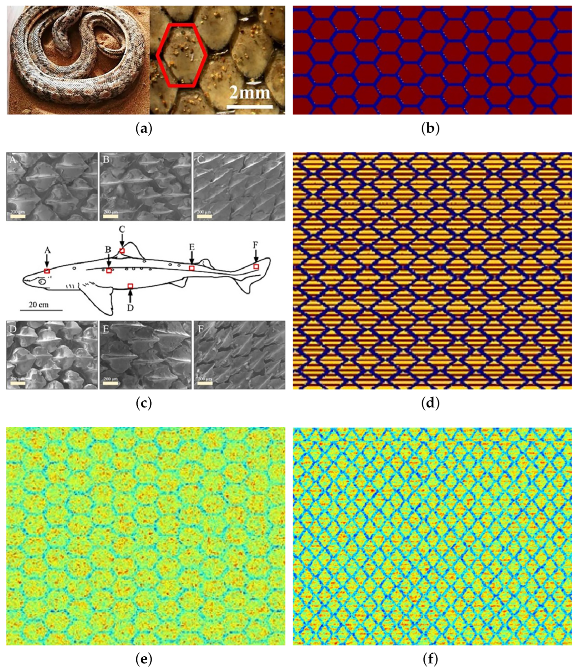
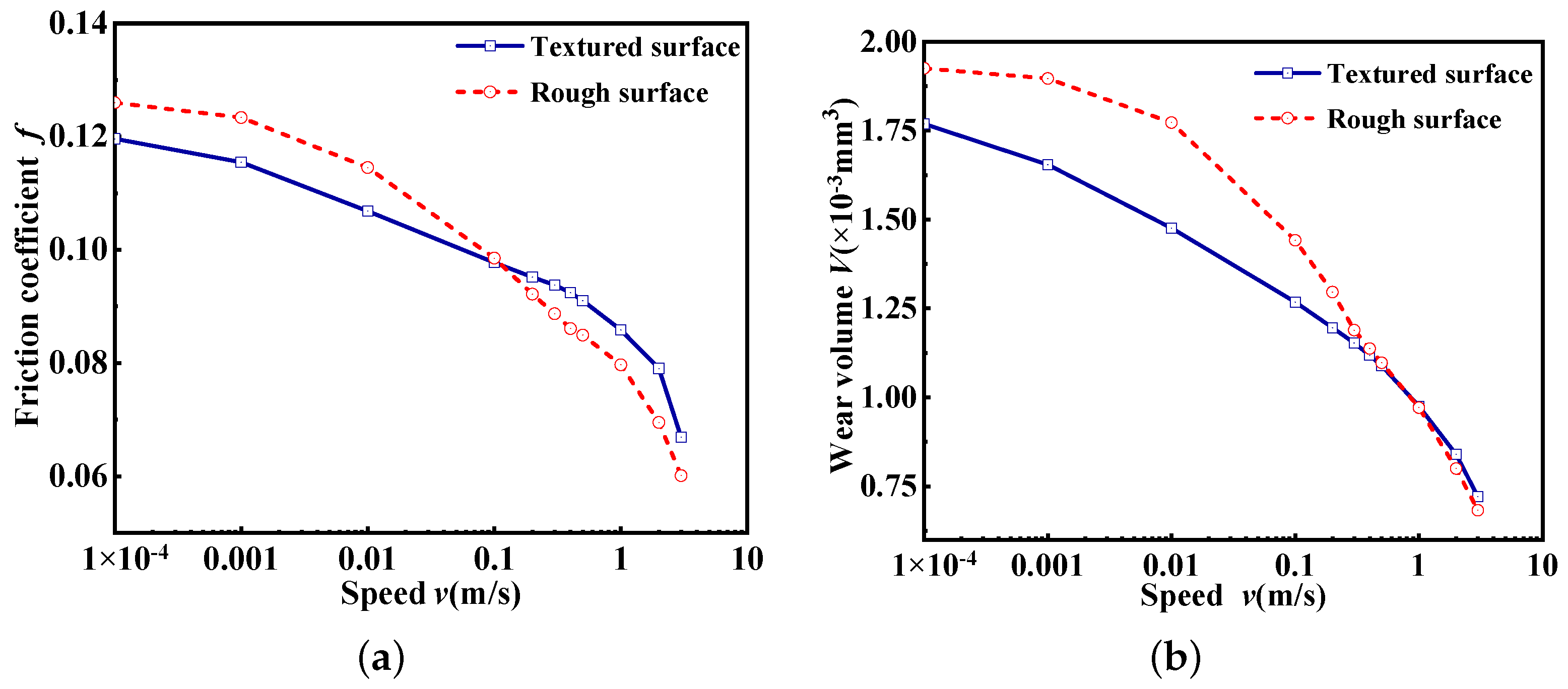
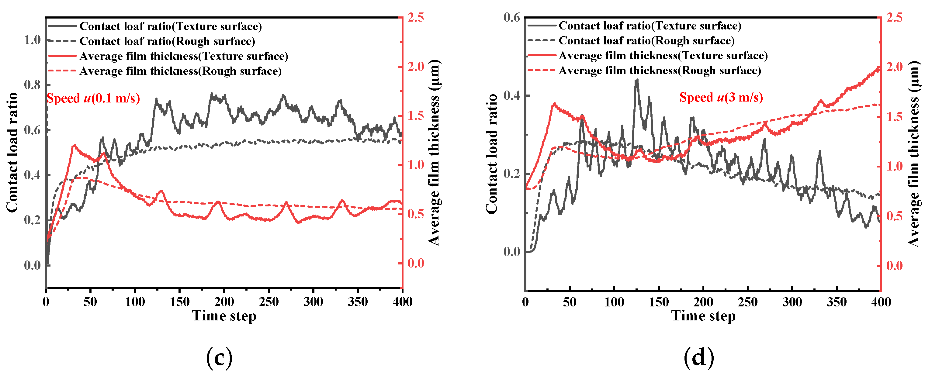
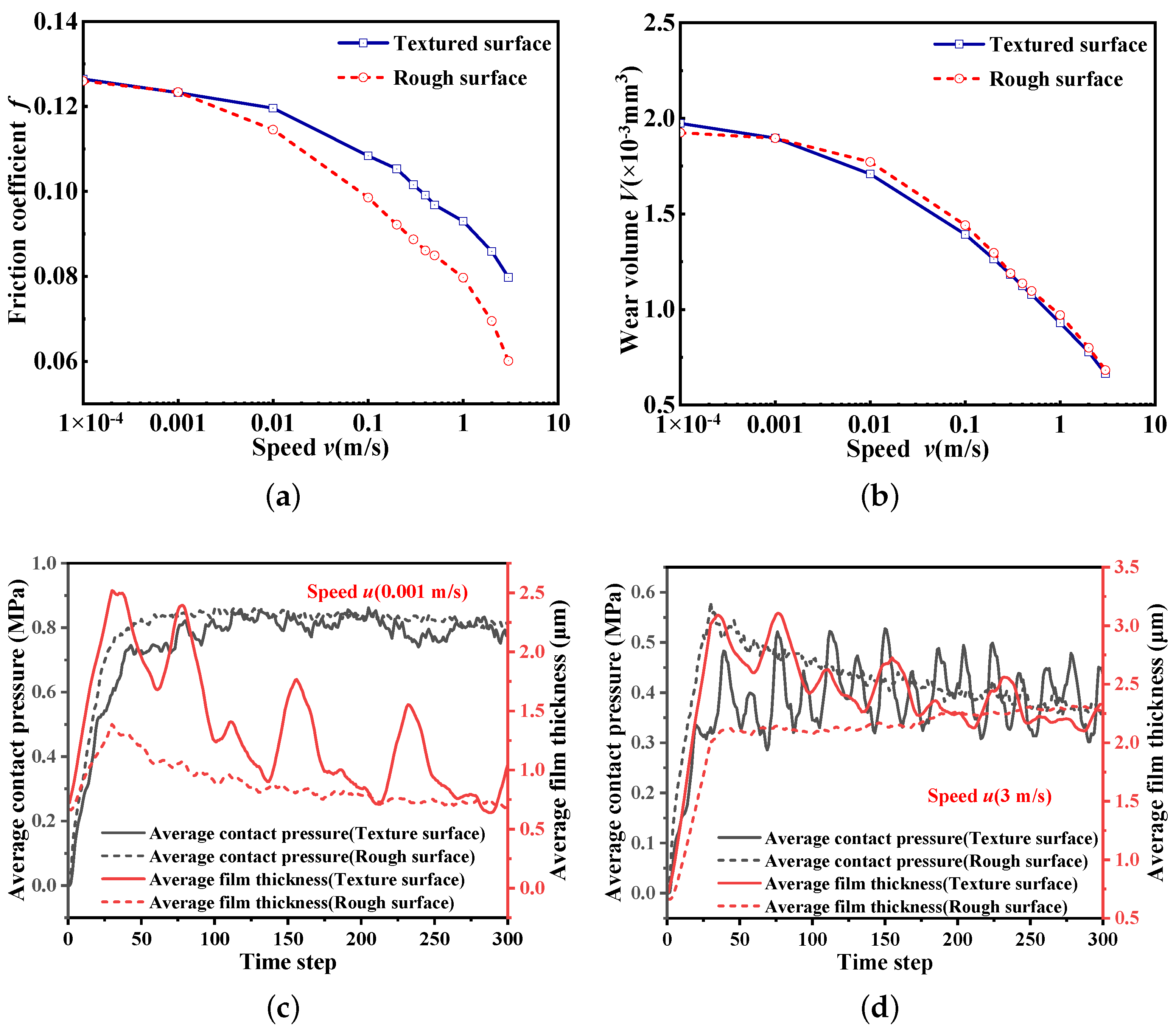
4.1. Biomimetic Surface Analysis of Snakeskin

Figure 4 depicts the trends in the friction coefficient and wear volume of the contact interface with increasing velocity under the line-contact condition. It can be seen in Figure 4a,b that the friction coefficient and wear volume of the textured surface are greater than those of the rough surface in most cases. However, when the speed is high (greater than 1 m/s), the friction coefficient of the textured surface is smaller than that of the rough surface, and the wear volumes of the textured surface and the rough surface begin to approach each other. An increase in the surface velocity increases the entrainment velocity at the inlet. The increased flow velocity of the lubricating fluid increases the lubricating fluid entering the grooves of the biomimetic texture, which directly increases the hydrodynamic pressure in the contact area. Figure 4c,d demonstrate this point and provide the contact load ratio (load supported by surface contact divided by total load) and the dimensionless mean film thickness for velocities of 0.1 and 3 m/s. The increase in speed increases the average film thickness of the bionic-textured surface. The dynamic pressure effect is enhanced, resulting in a smaller contact load ratio compared to that of the ordinary rough surface, and finally, the friction force is reduced. At low speeds, the low entrainment speed cannot make the lubrication fully enter the grooves of the complex bionic texture, so the average oil film thickness is small and the contact load is relatively large. So, at low speeds, the textured form of the snakeskin is not conducive to the flow of lubricant, resulting in poor lubrication performance. As the speed increases, the lubrication condition improves, and the textured effect becomes prominent.
Figure 5 shows the effect of the slide-to-roll ratio on the tribological characteristics of the contact surface when the rolling speed was kept constant (0.4 m/s). The increase in the slide-to-roll ratio intensifies the mixed friction behavior in the contact area, and the sliding-contact behavior quickly smooths the surface roughness. So, the wear volume increases with the increasing slide-to-roll ratio, whereas the friction coefficient decreases. Meanwhile, when the slide-to-roll ratio exceeds 1.4, the friction coefficient of the textured surface is smaller than that of the rough surface. Figure 5c,d illustrate that after the rough peaks in the rough contact area are worn to a certain extent, the microgrooves created by the biomimetic texture become the main area for storing lubricating fluid. With the increasing thickness of the lubricating film in the contact area, the lubrication performance improves.
Under the point-contact condition, because the contact area is small, the time step does not need to be too long, and 300 time steps are selected. As shown in Figure 6a,b, the friction coefficient and wear volume of the textured surface are significantly smaller than those of the rough surface at lower velocities. However, when the speed is greater than 0.5 m/s, the results are the opposite. Figure 6c,d illustrate that under the point-contact condition, due to the small contact area, a low entrainment speed can cause the lubricant to flow into the bionic texture, thereby reflecting the enhancement effect of the hydrodynamics of the texture. Consequently, the average oil film thickness of the bionic-textured surface is larger than that of the ordinary rough surface. The average contact pressure of the bionic-textured snakeskin surface is larger than that of the ordinary surface, indicating that in some local contact areas, the mixed friction behavior of the bionic-textured snakeskin surface is more intense compared to the ordinary surface. At high entrainment speeds, the lubricating fluid can quickly fill the contact area between the ordinary rough surfaces or biomimetic-textured surfaces and the counterbody, thereby increasing the average film thickness. However, the average film thickness of the bionic-textured snakeskin is smaller because the bionic-textured snakeskin surface will guide the lubricating fluid to flow to both sides of the contact area, forming two new areas of pressure divergence zones. Therefore, under the point-contact condition, the textured snakeskin surface can only improve the friction and wear characteristics of the contact surface at low speeds.

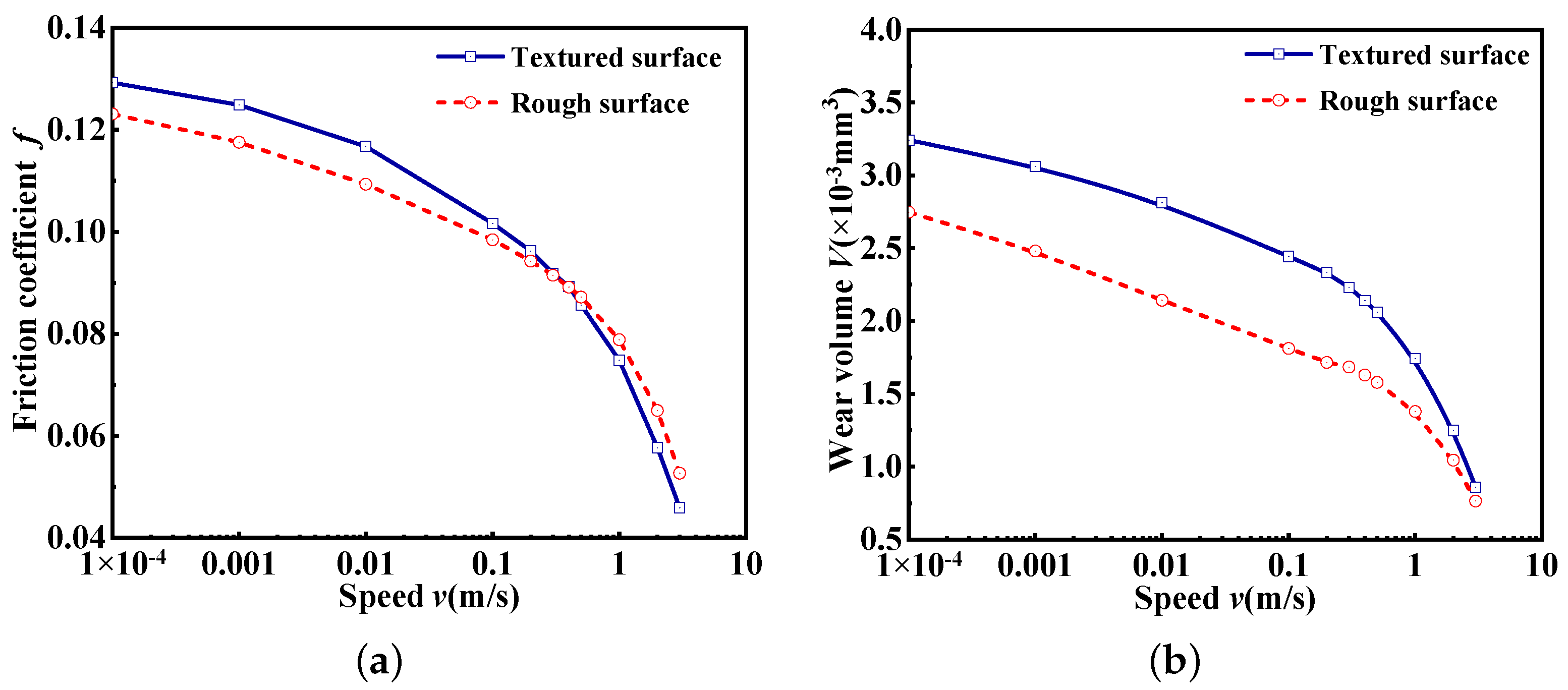
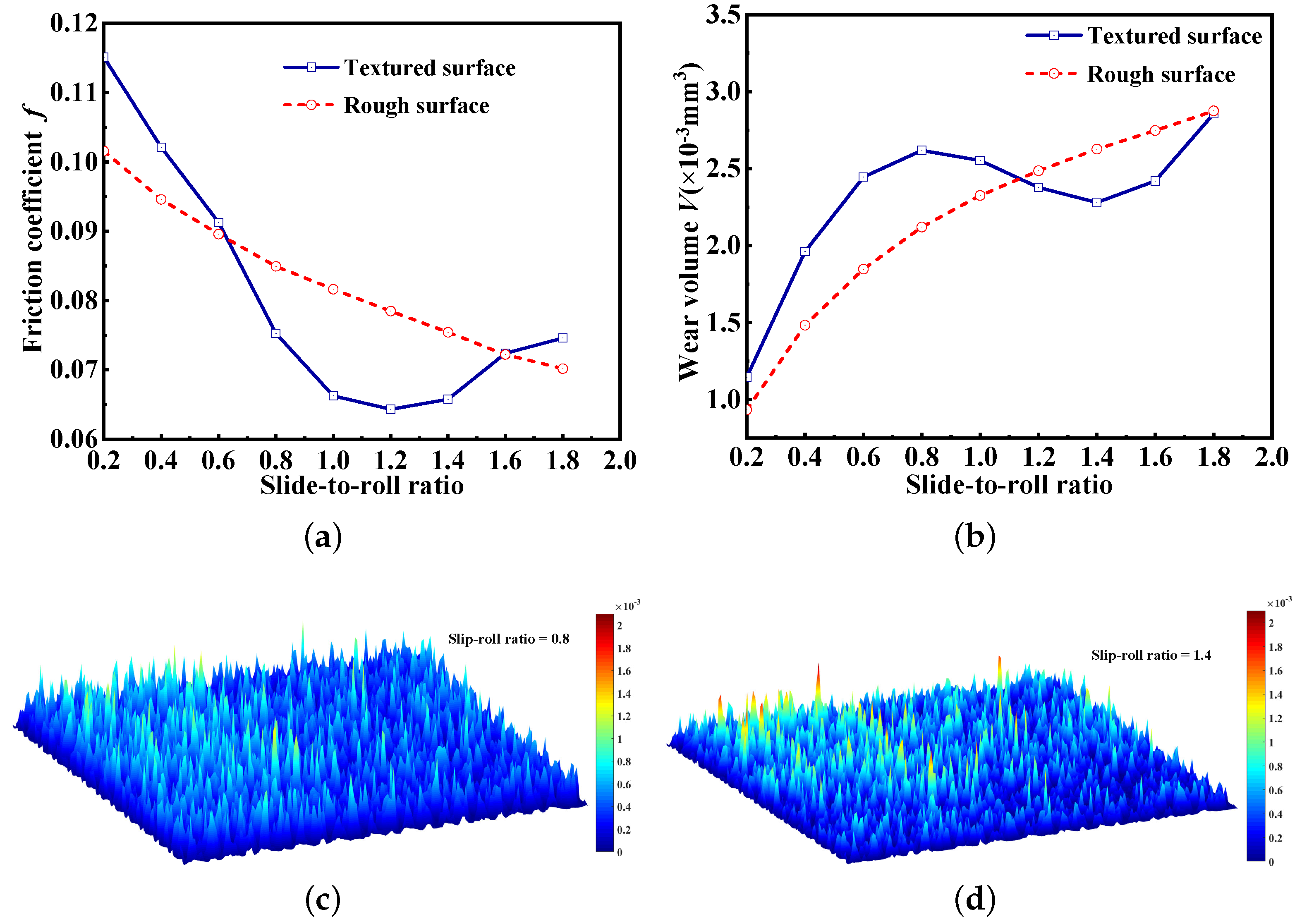
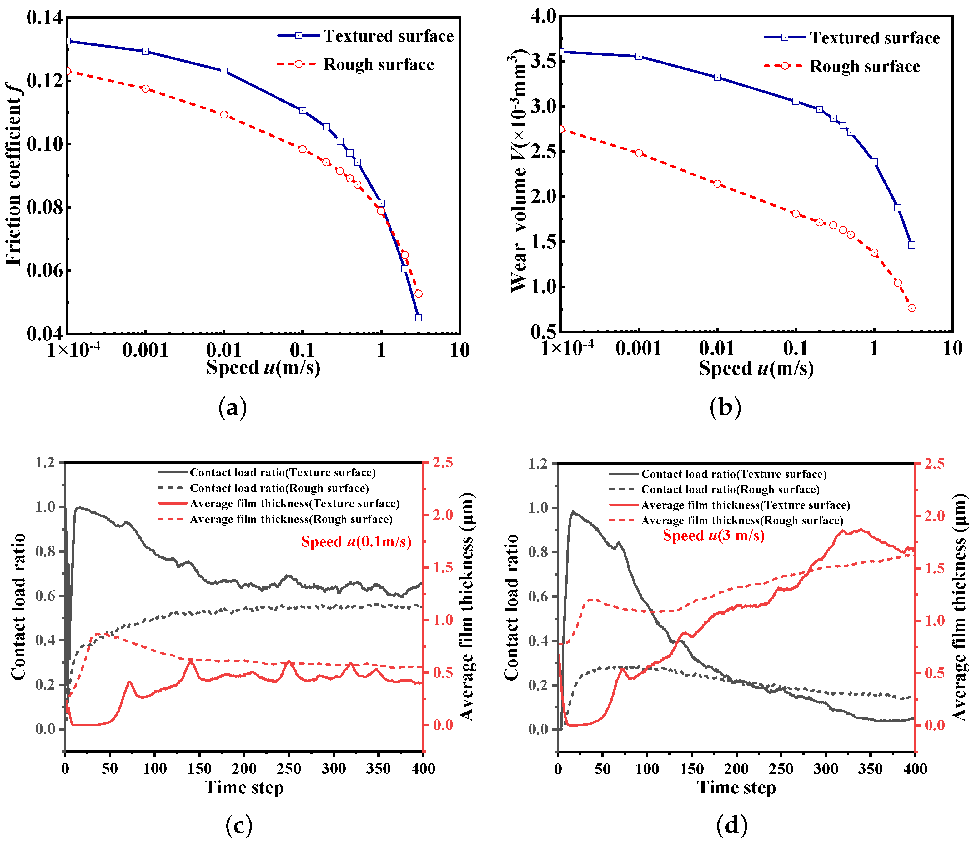
4.2. Biomimetic Surface Analysis of Sharkskin

Figure 7 shows that the sharkskin texture is similar to the snakeskin texture under the line-contact condition, and a lower friction coefficient can be achieved at higher speeds (more than 0.5 m/s). Concurrently, the wear volume also approaches that of the ordinary rough surfaces. The discrepancies in the tribological characteristics of the two textured surfaces arise because when the friction coefficient of the sharkskin surface is slightly smaller than that of the rough surface, the corresponding speed is smaller, and the wear volume is closer to that of the rough surface. The most notable difference between the sharkskin texture and the snakeskin texture is that in addition to the regular microgrooves, the former has bar-shaped protrusions on the rough surface, equivalent to forming a secondary texture on the rough surface. This secondary texture creates a composite wedge effect on the sharkskin-textured surface, which further increases the average film thickness, as shown in Figure 7c,d. When comparing Figure 4c,d and Figure 7c,d, it can be seen that the sharkskin texture has a larger average film thickness and a smaller contact load ratio compared to the snakeskin texture under the same working conditions. This means that the tribological properties of sharkskin texture are better than snakeskin texture under the line-contact condition.
Figure 8a indicates that when the slide-to-roll ratio is 1.2, the sharkskin-textured surface can achieve the smallest friction coefficient with a constant rolling speed (0.4 m/s). Meanwhile, when the slide-to-roll ratio is 1.4, the wear volume of the sharkskin-textured surface is less than that of the rough surface. It can be seen in Figure 8c,d that the heights of the rough peaks (red parts) in the contact area are significantly smaller when the rolling ratio is 1.4 compared to when the rolling ratio is 0.8. Simultaneously, according to the color bars, the heights of all rough peaks on the surface in Figure 8d are reduced. Figure 8 illustrates that the friction and anti-wear properties of the sharkskin texture are improved when the slide-to-roll ratio is in the range of 0.8 to 1.6 compared to when the slide-to-roll ratio is 0.8.
Figure 9 shows a comparison of the friction coefficient and wear volume of the textured surface of sharkskin and the corresponding rough surface under the point-contact condition. As shown in Figure 9a, the friction coefficient of the textured surface of sharkskin is obviously larger than that of the rough surface. Figure 9b indicates that the wear volume of the textured surface is very close to that of the rough surface. The bar-shaped protrusions of the sharkskin texture increase the frictional behavior of the surface in a small contact area (point contact), blocking the flow of lubricant to a certain extent. At the same time, similar to the texture of the bionic snakeskin, the rhombic texture forms new divergent areas on both sides, and the coupling of these factors causes a fluctuation in the thickness of the oil film. Meanwhile, Figure 8c,d show that the oscillations of the average contact pressure and film thickness are exacerbated by the increase in speed. This means that the improvement of the sharkskin texture has no effect on the point-contact condition.

5. Conclusions

In the present study, to reduce the energy consumption of rail transit, the tribological properties of bionic snakeskin and sharkskin rough surfaces of light rail bearing rollers at different speeds and roll ratios, including the friction coefficient and anti-wear properties, are studied. Some interesting conclusions are as follows:
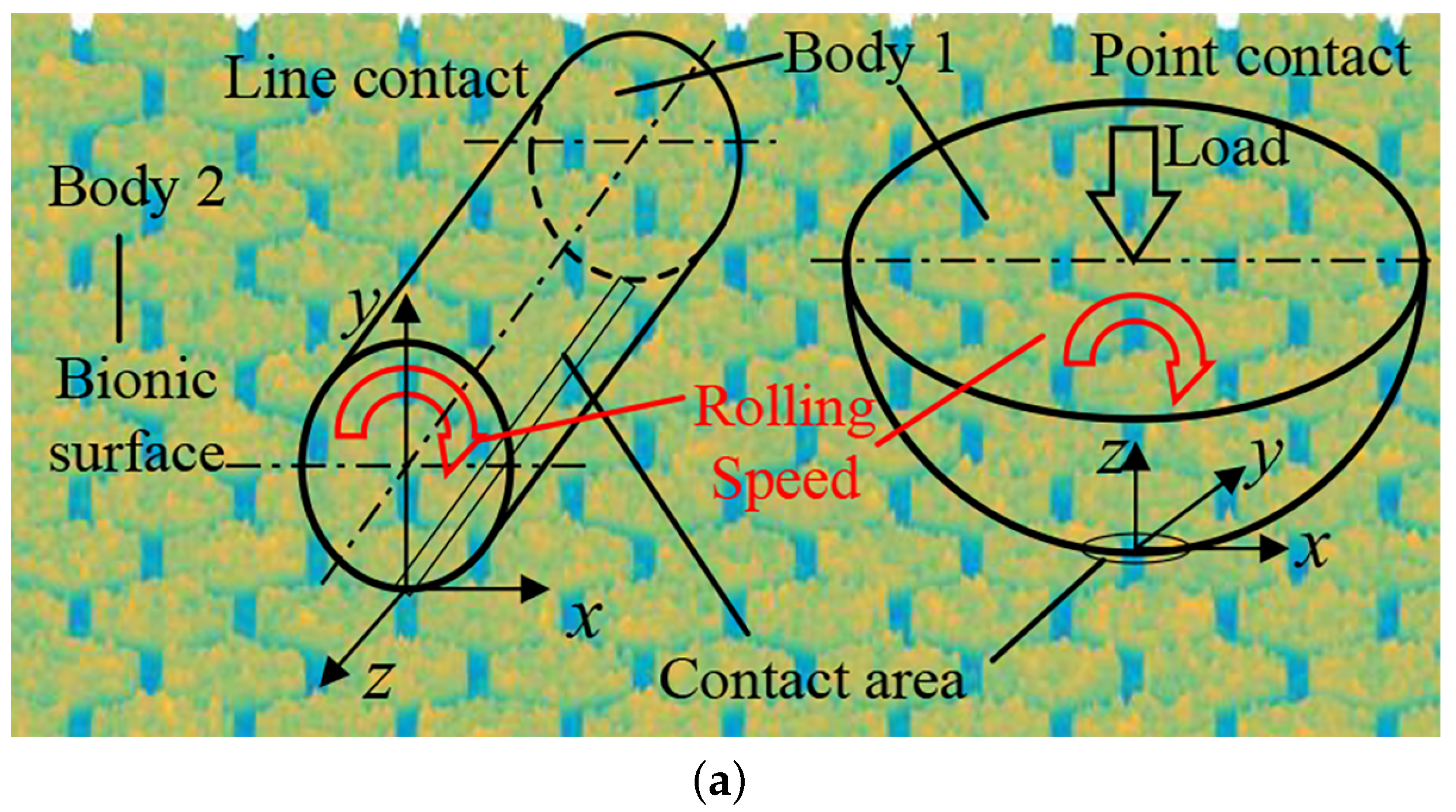
  • Under the line-contact condition, both biomimetic-textured surfaces can reduce the coefficient of friction and wear volume at high speeds. However, under point-contact conditions, the snakeskin texture shows a better texture effect at low speeds. The sharkskin texture can cause the surface properties to deteriorate under the point-contact condition and is not recommended.
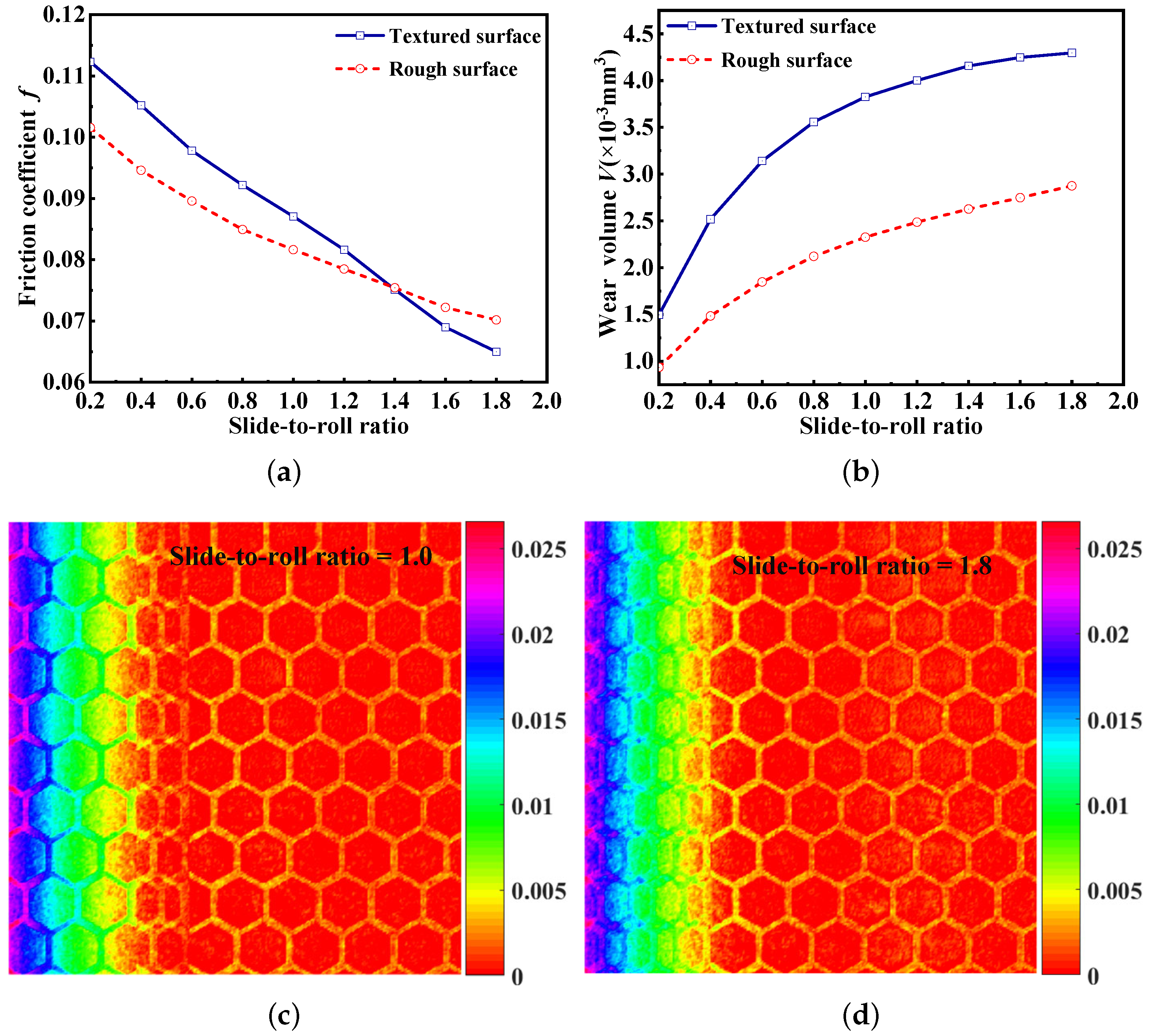
  • The textured snakeskin surface can achieve a smaller friction coefficient compared to the rough surface at a larger slide-to-roll ratio. The textured sharkskin surface achieved the minimum friction coefficient at a specific slide-to-roll ratio of 1.2 in the present study.
  • By comparing all the simulation results, it can be seen that the effect of biomimetic texture on the characteristics of the surfaces has a strong relationship with the working and contact conditions. The physical properties of the textured surfaces tend to degrade under some conditions.
  • The current work only studied the tribological properties of the two bionic surfaces under fixed loads, but in the actual position of a train, the loads change and there may be better surface textures, so future research will consider the friction and wear properties of other new textured surfaces under varying loads.
In summary, bionic-textured surfaces can improve the surface performance of train-bearing rollers to a certain extent. However, for the best results, specific working conditions are required. Using bionic textures or forming multi-layer textures with other textures under specific conditions can achieve the effect of energy saving and environmental protection of rail transit to a certain extent.

Author Contributions

Conceptualization, J.C. and G.C.; methodology, C.W., J.C. and G.C.; software, J.C. and G.C.; validation, C.W. and D.T.; formal analysis, C.W.; investigation, C.W.; resources, J.W.; data curation, C.W.; writing—original draft preparation, C.W.; writing—review and editing, J.C.; visualization, C.W.; supervision, J.W.; project administration, J.W. All authors have read and agreed to the published version of the manuscript.

Funding

This research was funded by the National Natural Science Foundation of China under grant numbers 52105052 and 51975064 and the General Projects of Basic Science and Frontier Technology Research of Chongqing grant numbers cstc2021jcyj-msxmX1069 and cstc2021jcyj-msxmX1056.

Institutional Review Board Statement

Not applicable.

Informed Consent Statement

Not applicable.

Data Availability Statement

The main data have been presented in the form of figures and tables.

Acknowledgments

We are grateful to Xiang for his valuable advice in establishing the numerical calculation model.

Conflicts of Interest

The authors declare no conflict of interest.

Abbreviations

The following abbreviations and symbols are used in this manuscript:
EHLelastohydrodynamic lubrication
GTGreenwood and Tripp
ϕ k , l independent random phase angle
S k , l spectral density function
R r , s autocorrelation function
σ composite roughness
β x , β y correlation length coefficients in x- and y-directions, respectively
h 0 , h p height of the non-textured surface
( x c , y c ) coordinates of the textured surface’s center
ledge length of the textured surface
h , h p height of the final textured surface and bar-shaped protrusions, respectively
y c centerline of the bar-shaped protrusions
dhalf-width of the bar-shaped protrusions
h g lubrication gap
P h hydrodynamic pressure
ρ density of the lubricant
η viscosity of the lubricant
uentrainment velocity
Wexternal load
ptransient pressure
E * composite elastic modulus
β radius of asperity
Ddensity of asperity
kwear coefficient of the contact surfaces
H B hardness of the contact surfaces
Δ x , Δ y dimensions of the grid
Γ 1 , Γ 2 boundary and area of the solution domain, respectively
s p areal density
ffriction coefficient

References

  1. Sun, J.; Sial, M.S.; Deng, D.; Saxunova, D.; Haider, A.; Khan, M.A. The Significance of Urban Rail Transit Systems in Mitigating Air Pollution Effects: The Case of China. Sustainability 2022, 14, 13944. [Google Scholar] [CrossRef]
  2. Gao, Z.; Yang, L. CORRECTION to: Energy-saving operation approaches for urban rail transit systems. Front. Eng. Manag. 2022, 9, 698. [Google Scholar] [CrossRef]
  3. Wang, Z.; Allen, P.; Mei, G.; Wang, R.; Yin, Z.; Zhang, W. Influence of wheel-polygonal wear on the dynamic forces within the axle-box bearing of a high-speed train. Veh. Syst. Dyn. 2020, 58, 1385–1406. [Google Scholar] [CrossRef]
  4. Wu, Z.; Bao, H.; Xing, Y.; Liu, L. Tribological characteristics and advanced processing methods of textured surfaces: A review. Int. J. Adv. Manuf. Technol. 2021, 114, 1241–1277. [Google Scholar] [CrossRef]
  5. Greiner, C.; Schäfer, M. Bio-inspired scale-like surface textures and their tribological properties. Bioinspirat. Biomimet. 2015, 10, 044001. [Google Scholar] [CrossRef]
  6. Guo, P.; Zhang, K.; Yasuda, Y.; Yang, W.; Galipon, J.; Rival, D.E. On the influence of biomimetic shark skin in dynamic flow separation. Bioinspirat. Biomimet. 2021, 16, 034001. [Google Scholar] [CrossRef]
  7. Li, X.; Deng, J.; Yue, H.; Ge, D.; Zou, X. Wear performance of electrohydrodynamically atomized WS2 coatings deposited on biomimetic shark-skin textured surfaces. Tribol. Int. 2019, 134, 240–251. [Google Scholar] [CrossRef]
  8. Rong, W.; Zhang, H.; Zhang, T.; Mao, Z.; Liu, X.; Song, K. Drag Reduction Using Lubricant-Impregnated Anisotropic Slippery Surfaces Inspired by Bionic Fish Scale Surfaces Containing Micro-/Nanostructured Arrays. Adv. Eng. Mater. 2021, 23, 2000821. [Google Scholar] [CrossRef]
  9. Domel, A.G.; Saadat, M.; Weaver, J.C.; Haj-Hariri, H.; Bertoldi, K.; Lauder, G.V. Shark skin-inspired designs that improve aerodynamic performance. J. R. Soc. Interface 2018, 15, 20170828. [Google Scholar] [CrossRef]
  10. Ballesteros, L.M.; Zuluaga, E.; Cuervo, P.; Rudas, J.S.; Toro, A. Tribological behavior of polymeric 3D-printed surfaces with deterministic patterns inspired in snake skin morphology. Surf. Topogr. Metrol. Prop. 2021, 9, 014002. [Google Scholar] [CrossRef]
  11. Tsipenyuk, A.; Varenberg, M. Use of biomimetic hexagonal surface texture in friction against lubricated skin. J. R. Soc. Interface 2014, 11, 20140113. [Google Scholar] [CrossRef]
  12. Li, X.; Deng, J.; Liu, L.; Zhang, L.; Sun, J.; Ge, D.; Liu, Y.; Duan, R. Tribological properties of WS2 coatings deposited on textured surfaces by electrohydrodynamic atomization. Surf. Coat. Technol. 2018, 352, 128–143. [Google Scholar] [CrossRef]
  13. Hsu, S.M.; Jing, Y.; Zhao, F. Self-adaptive surface texture design for friction reduction across the lubrication regimes. Surf. Topogr. Metrol. Prop. 2015, 4, 014004. [Google Scholar] [CrossRef]
  14. Grützmacher, P.G.; Profito, F.J.; Rosenkranz, A. Multi-scale surface texturing in tribology—Current knowledge and future perspectives. Lubricants 2019, 7, 95. [Google Scholar] [CrossRef]
  15. Rosenkranz, A.; Grützmacher, P.G.; Murzyn, K.; Mathieu, C.; Mücklich, F. Multi-scale surface patterning to tune friction under mixed lubricated conditions. Appl. Nanosci. 2021, 11, 751–762. [Google Scholar] [CrossRef]
  16. Hu, Y.Z.; Zhu, D. A Full Numerical Solution to the Mixed Lubrication in Point Contacts. J. Tribol. 2000, 122, 1–9. [Google Scholar] [CrossRef]
  17. Wang, Q.J.; Zhu, D. Virtual Texturing: Modeling the Performance of Lubricated Contacts of Engineered Surfaces. J. Tribol. 2005, 127, 722–728. [Google Scholar] [CrossRef]
  18. Xiang, G.; Yang, T.; Guo, J.; Wang, J.; Liu, B.; Chen, S. Optimization transient wear and contact performances of water-lubricated bearings under fluid-solid-thermal coupling condition using profile modification. Wear 2022, 502, 204379. [Google Scholar] [CrossRef]
  19. Cai, J.; Xiang, G.; Li, S.; Guo, J.; Wang, J.; Chen, S.; Yang, T. Mathematical modeling for nonlinear dynamic mixed friction behaviors of novel coupled bearing lubricated with low-viscosity fluid. Phys. Fluids 2022, 34, 093612. [Google Scholar] [CrossRef]
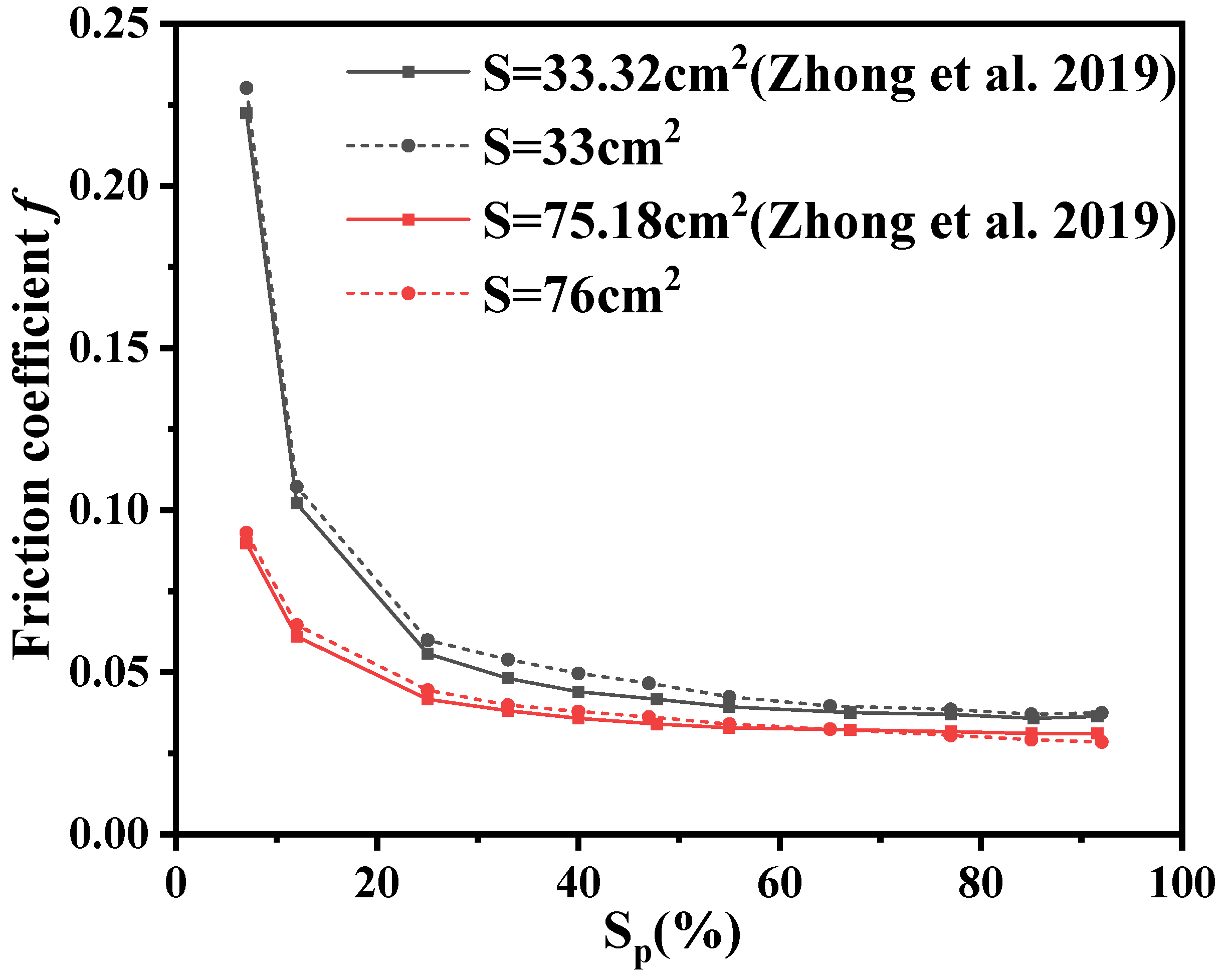
  20. Zhong, Y.; Zheng, L.; Gao, Y.; Liu, Z. Numerical simulation and experimental investigation of tribological performance on bionic hexagonal textured surface. Tribol. Int. 2019, 129, 151–161. [Google Scholar] [CrossRef]
  21. König, F.; Rosenkranz, A.; Grützmacher, P.G.; Mücklich, F.; Jacobs, G. Effect of single-and multi-scale surface patterns on the frictional performance of journal bearings–a numerical study. Tribol. Int. 2020, 143, 106041. [Google Scholar] [CrossRef]
  22. Wu, J.J. Simulation of rough surfaces with FFT. Tribol. Int. 2000, 33, 47–58. [Google Scholar] [CrossRef]
  23. Ren, N.; Zhu, D.; Chen, W.W.; Liu, Y.; Wang, Q.J. A Three-Dimensional Deterministic Model for Rough Surface Line-Contact EHL Problems. Am. Soc. Mech. Eng. 2009, 131, 011501. [Google Scholar] [CrossRef]
  24. Chun, S.M.; Khonsari, M.M. Wear simulation for the journal bearings operating under aligned shaft and steady load during start-up and coast-down conditions. Tribol. Int. 2016, 97, 440–466. [Google Scholar] [CrossRef]
  25. Liu, B.; Bruni, S.; Lewis, R. Numerical calculation of wear in rolling contact based on the Archard equation: Effect of contact parameters and consideration of uncertainties. Wear 2022, 490, 204188. [Google Scholar] [CrossRef]
  26. Beheshti, A.; Khonsari, M. An engineering approach for the prediction of wear in mixed lubricated contacts. Wear 2013, 308, 121–131. [Google Scholar] [CrossRef]
Figure 1. Geometric topography. (a) Real snakeskin surfaces. (b) Simulated snakeskin-textured surfaces. (c) Real sharkskin surfaces. (d) Simulated sharkskin-textured surfaces. (e) Simulated snakeskin-textured surfaces with realistic roughness. (f) Simulated sharkskin-textured surfaces with realistic roughness.
Sustainability 15 13054 g001
Figure 2. Schematic diagrams. (a) The contact conditions of the numerical model. (b) The flowchart of the numerical calculation.
Sustainability 15 13054 g002aSustainability 15 13054 g002b
Figure 3. Verification of the effect of areal density on the friction coefficient in Zhong et al.’s research [20].
Sustainability 15 13054 g003
Figure 4. Effect of speed on the friction coefficient and wear volume under the line-contact condition. (a) Friction coefficient. (b) Wear volume. (c) Average film thickness versus time step. (d) Contact load ratio versus time step.
Sustainability 15 13054 g004
Figure 5. Effect of the slide-to-roll ratio on the tribological parameters. (a) Friction coefficient. (b) Wear volume. (c) The dimensionless film thickness when the slip ratio is 1. (d) The dimensionless film thickness when the slip ratio is 1.8.
Sustainability 15 13054 g005
Figure 6. Effect of speed on the friction coefficient and wear volume under the line-contact condition. (a) Friction coefficient. (b) Wear volume. (c) Average film thickness versus time step. (d) Contact load ratio versus time step.
Sustainability 15 13054 g006aSustainability 15 13054 g006b
Figure 7. Effect of speed on the friction coefficient and wear volume under the line-contact condition. (a) Friction coefficient. (b) Wear volume. (c) Average film thickness versus time step. (d) Contact load ratio versus time step.
Sustainability 15 13054 g007aSustainability 15 13054 g007b
Figure 8. Effect of speed on the friction coefficient and wear volume under the line-contact condition. (a) Friction coefficient. (b) Wear volume. (c) The wear volume of the textured surface with a slide-to-roll ratio equal to 0.8. (d) The wear volume of the textured surface with a slide-to-roll ratio equal to 1.4.
Sustainability 15 13054 g008
Figure 9. Effect of speed on the friction coefficient and wear volume under the line-contact condition. (a) Friction coefficient. (b) Wear volume. (c) Average film thickness versus time step. (d) Contact load ratio versus time step.
Sustainability 15 13054 g009
Table 1. The parameters used to generate the two bionic surfaces.
SnakeskinSharkskin
ParameterValueParameterValue
Density20%Density35%
Length30 μ mLength30 μ m
Depth2 μ mDepth2 μ m
Roughness1 μ mRoughness1 μ m
Bar-shaped protrusions1.5 μ m
Table 2. The parameters used by Zhong et al. [20].
ParameterValue
Groove depth10 μ m
Sliding speed1 m/s
Groove depth10 μ m
Total area33.21, 75.18 cm 2
Table 3. The parameters for the simulation.
ParameterValueParameterValue
Load1000 NElastic modulus200 GPa
Hardness4.0 GPaPoisson’s ratio0.3
Density7.865 g/ cm 3 Composite roughness1 μ m
Oil viscosity0.096 Pa/sSpeed (rolling speed)0.0001–3 m/s
Slide-to-roll ratio0.2–1.8Radius of counterbody R x 60.0 mm
Time step1 sNumber of time step300 or 400
Disclaimer/Publisher’s Note: The statements, opinions and data contained in all publications are solely those of the individual author(s) and contributor(s) and not of MDPI and/or the editor(s). MDPI and/or the editor(s) disclaim responsibility for any injury to people or property resulting from any ideas, methods, instructions or products referred to in the content.

