Abstract
As the use of Darrieus turbines in water is becoming increasingly popular in the field of renewable energy, it is essential to explore and evaluate existing research efforts. The situation of the Darrieus water turbine in water still requires further discussion. This paper aims to provide a comprehensive review of optimization methods for Darrieus water turbines, addressing the challenges associated with their efficiency, start-up, and stability. This work summarizes and evaluates the findings of previous studies, focusing on the features of experimental and numerical methods. Influence of geometric parameters, including height-diameter ratio, solidity, torsional angle, and airfoil are also talked into. The existing research adopts solidity values ranging from 0.1 to 0.4, but the design experience is not as extensive as that of the Darrieus wind turbine. Further discussions are still needed on the optimal power coefficient and tip speed ratio of the Darrieus water turbine. The research with a power coefficient ranging from about zero to above the Betz limit needs further summarization. Various optimization strategies, such as multi-turbine arrangement, coupling with Savonius turbines, and blade pitching, are also discussed. By offering insights into the current state of optimization works for Darrieus water turbines, this review aims to facilitate future research, bridge existing gaps in the field, further enrich the utilization of ocean currents, and improve the structure of renewable energy.
1. Background and Characteristics of Darrieus Turbine
The Darrieus turbine was proposed by Darrieus in 1931 as a vertical-axis lift-type turbine. It was a cross-flow turbine and had the highest theoretical efficiency among the vertical-axis turbines [1].
With its large torque ripple, it was not fully developed in the 1930s. In the 1970s, engineers in Canada and the United States began to study the vertical axis lift-type wind turbine as a source of power generation, and wind turbine research gradually emerged, but in the 1990s, wind turbine research stagnated. The wind turbine industry has enjoyed a renaissance since 2000 [2], with turbines being considered for offshore wind power [3,4] and underwater power generation [5]. The Darrieus wind turbine was developed earlier, and the research and applications were relatively more mature than those of the Darrieus water turbine [6,7].
The Darrieus turbine has great potential for the utilization of water flow [8]. Ocean data indicate that the flow speed in most areas of the oceans is low and enough for the Darrieus turbine to operate [9,10]. The application of the Darrieus turbine in the ocean for tidal current utilization gained more interest [11,12]. Seabed scour induced by Darrieus turbine was researched for utilization in rivers or seas [13,14]. Low-head water utilization with Darrieus turbines became a trend [15,16]. Darrieus turbines could also be installed in underwater mooring platforms to utilize discharged water from industries, outflow of boats [17], and water in farms [18]. The cavitation of Darrieus turbines was considered due to its fluctuation at a high running speed [19,20].
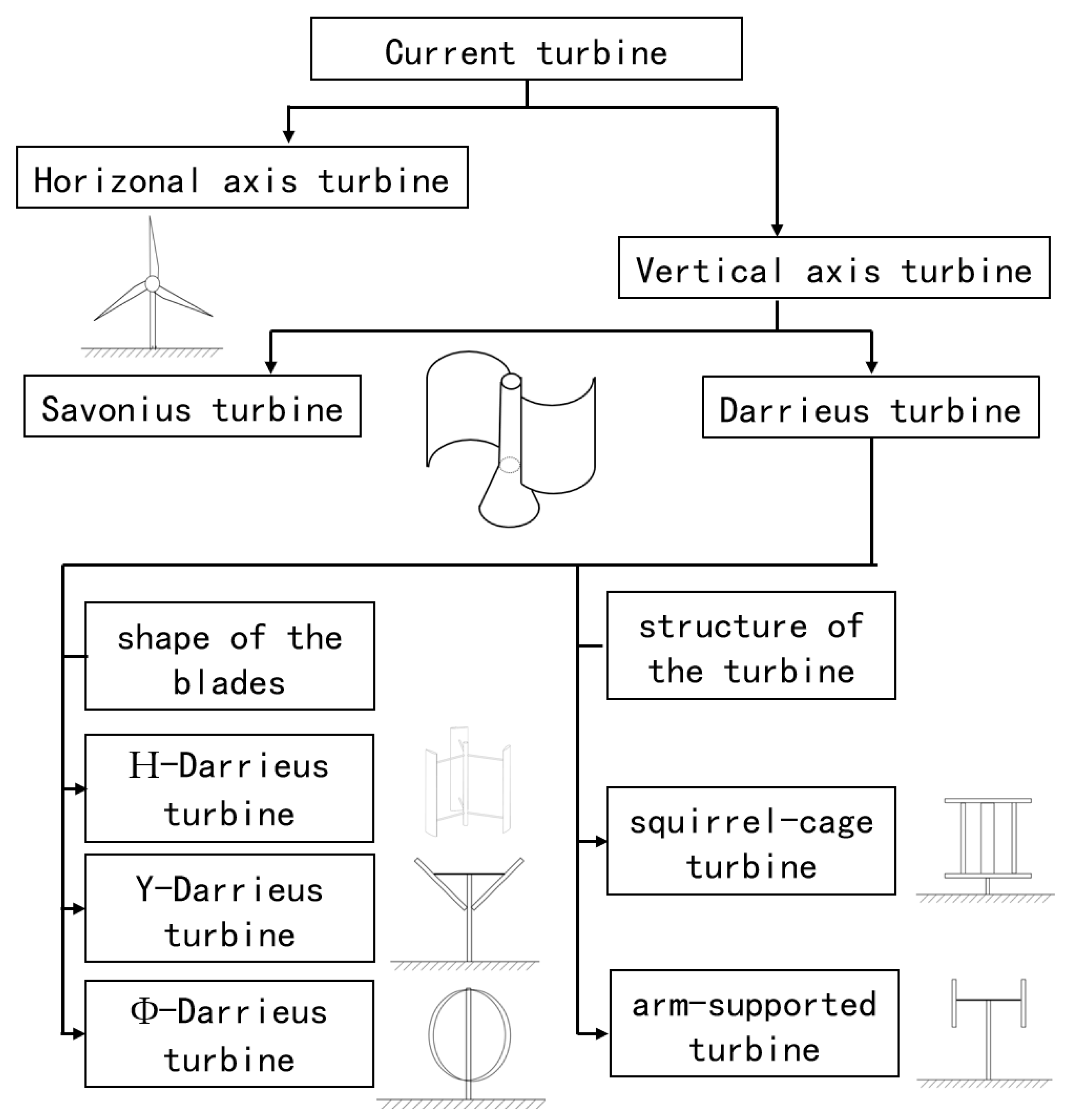
According to the installation mode of the turbine [21], the turbines can be divided into vertical axis type and horizontal axis type as in Figure 1. Most vertical-axis turbines have the design consideration that the horizontal flow in any direction can be utilized [22,23], while the horizontal axis can utilize the flow energy in only one horizontal direction by tracking and changing the direction [24]. The Darrieus turbine can also be installed with a horizontal axis [25,26] to utilize shallow water, and the turbines cannot be fully immersed to generate power but can still utilize water in two directions [27], which needs multiphase modeling [28].
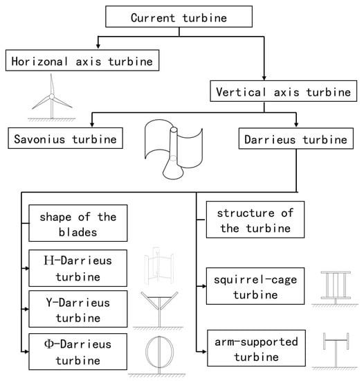
Figure 1.
Classification and branches of the Darrieus turbine.
The main branches of Darrieus turbines include H-type, oval (or Φ-type), Y-type, and diamond (variable angle) according to the blade shape parallel to the shaft surface. Delta blades contain symmetric helical structures [29]. The squirrel-cage type replaces the supporting structure of the intermediate shaft with the upper and lower cover plates. The original Gorlov type [30] was the twisted squirrel-cage type. The oval Darrieus turbine can reduce the influence of centrifugal load on the structure; the Y and diamond shape can control the power output to change the angle.
In recent years, some progress has been made in the optimization of Darrieus water turbines [31]. Idénergie Inc. has designed a co-located direct-drive generator turbine device, claiming a daily power generation of 12 kWh at a water depth of 0.6 m and flow speeds ranging from 1 m/s to 3 m/s. The Ocean Renewable Power Company attached four Gorlov turbines to a generator, claiming a power generation of 25 kW [32]. However, the company’s profitability is moderate, and the industry scale is limited, indicating the need for further optimization and design in this field. By summarizing the purposes, parameters, and methods of optimization, this paper presents the recommended methods and parameters of optimization. Future design and optimization of the Darrieus turbine can refer to the results for primary designs.
2. Parameters of Evaluation in Optimization
2.1. Power Coefficient and Tip Speed Ratio
The power coefficient was often defined as the ratio of the turbine power to the incoming flow power of the frontal area, usually represented by . As shown in Equation (1) [33], the turbine power is torque T multiplied by angular velocity ω, and in the denominator represents the incoming flow velocity. A is the turbine frontal area. This area is the product of the turbine diameter and the turbine height of the Darrieus turbines. According to this parameter, the ability of the turbine to extract energy from the flowing ocean current can be reflected in the final power of the turbine. The torque can also reflect the output of the turbine, so the torque coefficient was used in some work for evaluation. The speed meets Equation (3) for the Darriues turbine, and a special quantity can be proposed separately as the ratio of vt and . In some studies, was used for description, which was exactly the same quantity as ; the symbol was different because the English word torque or moment was used to express torque.
Tip speed ratio (TSR) is the ratio of tip speed to incoming flow speed, commonly expressed by TSR or λ, as defined in Equation (5). The diameter of the cross-flow turbine is fixed, and the blade tip speed is as shown in Equation (3), which can finally be written in the form of Equation (6). The parameter TSR can reflect the angular velocity of the turbine under the same flow condition.
The -TSR curve drawn from the power coefficient and blade tip speed ratio shows the variation of turbine output with angular speed under the same flow condition. It was an important basis for determining speed conditions and working characteristics [34] and was thus one of the evaluation criteria for optimization and research. As shown in Figure 2 below, many works have obtained relevant data and drawn the characteristic curve through experiments or numerical methods [35,36,37]. With the increase of speed from zero, the power coefficient first increases and then decreases; a peak exists. The peak power coefficient varies in different studies, but generally for hydraulic turbines, the blade tip-specific speed corresponding to the highest efficiency point was less than 2.5.

Figure 2.
(a–c) Examples of experimental and numerical results of Cp-TSR curves [35,36,37].
2.2. Instantaneous Power Coefficient or Torque
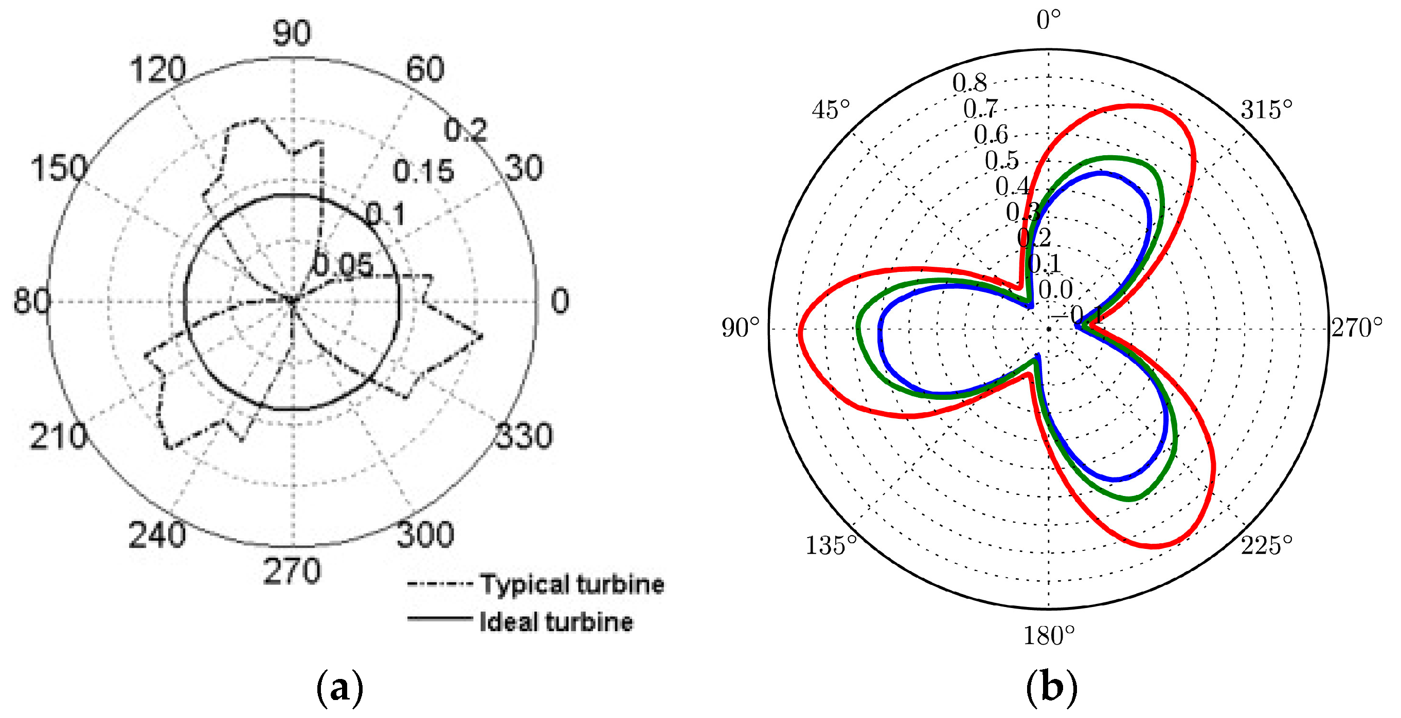
The instantaneous power coefficient/torque of the Darrieus changes periodically with the blade angular position, and the rotational speed of the actual turbine fluctuates with the changing power. The blade can provide a large torque before stalling at a small range of attack angle. After stalling, the blade torque drops rapidly. The minimum turbine torque has a great influence on start-up [38]. The lower ratio of maximum to minimum torque means more stability of the turbine, and the ideal torque and power were expected to be smooth during operation. The instantaneous power coefficient and torque were usually used to evaluate the turbine, as shown in Figure 3 [39,40]. Curves of a single blade were used to optimize some characteristics, and curves of turbines can show the fluctuations of an actual turbine. The cycles of torque and power can be better shown in curves with polar coordinates. The curves can be compared to improve optimization by relating power and torque with the optimization parameter.
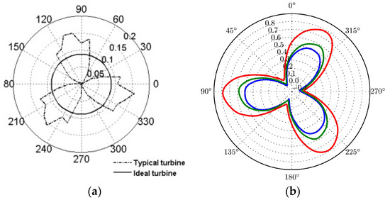
Figure 3.
(a) Dimensionless torque—azimuth angle curve [39] (b) Cp-angular curves for different calculation domains [40].
3. Research Methods
3.1. Numerical Methods
Due to the constantly changing blade attack angle during turbine operation, simply using blade lift and drag characteristics cannot accurately evaluate the performance of the turbine [41]. Modeling the turbine is necessary and accurate modeling of the dynamic stall is important [42,43]. There are many numerical methods to evaluate the performance of vertical axis lift turbines, including blade element theory, computational fluid dynamics, and vortex methods [44].
Several aerodynamic prediction models were established for Darrieus wind turbines in the 1970s and early 1980s and blade element momentum (BEM) methods were developed to evaluate turbine designs. The preliminary assumption of single-stream tube model was improved by the induced velocities corresponding to different phase angles in the multi-stream tube model, while the subsequent development of the double-actuator disk theory distinguishes between the upstream and downstream induced velocities [45]. With the database of lift and drag characteristics of airfoils, the performance of the turbine can be calculated with a relatively small computation. Many empirical models considering the dynamic stall of the turbine were proposed to correct the blade element momentum theory, and the corrected models maintained good consistency with experiments.
Santiago et al. [46] developed a BEM model for high-solidity vertical-axis tidal turbines. The dual-flow multitube model used a graphical approach to determine the axial inductance instead of the iterative method used in the traditional BEMT model. To solve the dynamic stall and flow expansion, the model also included the aspect ratio. The model was accurate for predicting the performance of high-solidity vertical-axis tidal turbines. It reproduced the phase and amplitude of the power curve, with an error of only 2.5% in the peak power coefficient. The blade element theory needs relatively few calculations, but the principle was different from that of CFD. However, the specific situation between the blade and the flow field cannot be obtained.
With the development of computer technology, CFD was a good alternative computing method. The foundations of all CFD algorithms include Navier–Stokes solutions, grid generation techniques, and numerical schemes for physical modeling of turbulence. The differences between Unsteady Reynolds averaged Navier–Stokes equations (URANS) and Reynolds averaged Navier–Stokes equations (RANS) are the unsteady quantity in the momentum equation and the time step. Steady RANS usually cannot simulate the dynamic stall during operation, and unsteady RANS was very commonly used in simulating Darrieus turbines [47,48,49]. In the RANS method, only the average flow rate is solved, and the Reynolds stress tensor is used to introduce the effect of turbulence. In calculating isotropic turbulence, the Reynolds tensor reduction rate is a scalar quantity that acts as an additional turbulent viscosity. In this case, the turbulent viscosity is related to one or two turbulent parameters, so the semi-empirical transport equation must be solved. The most popular models were the Spalart–Allmaras equation and two k-ω equations. Some numerical investigations were conducted at a high running speed with cavitation by using RANS methods [50,51,52].
The performance of the k-ω model is better than that of the k-𝜖 model near the wall. The k-ω model is extremely effective for flows that exhibit strong adverse pressure gradients and flow reversals, which are typically encountered in vertical axis turbines. The problem with the k-ω model is its extreme sensitivity to the value of ω at the non-rotating boundary of the shear flow [53]. In this sense, the k-ω model near the mixed wall and the k-𝜖 mixing model outside the wall established by Menter have advantages. The SST model performs satisfactorily in a decelerating boundary layer and is, therefore, effective in predicting separation.
One of the main contributions of SST is that the model can increase confidence in the computational results, especially for low Reynolds number flows. It is the model with the best near-wall handling capability. It can flexibly switch from the wall function method to the low Reynolds number scheme according to the grid spacing, which can usually improve the performance of the grid compared with other RANS models [54]. The SST model is superior to the other two-equation models in terms of numerical stability because it does not use the viscous damping function but uses the Dirichlet boundary condition directly. These factors make SST an ideal choice for numerical simulation modeling.
The computational complexity of CFD leads to significant computational costs, and many computational methods were developed [55]. Coupling the BEM calculation in the blade area with the RANS in another area can also raise the efficiency in evaluating the distribution of multiple turbines. Ikoma et al. [56] established a database of blade lift and drag characteristics based on experimentally validated CFD results, and the BEM method was used to efficiently design turbines. Good results can be obtained with LES and DES methods, but they require much more calculation than RANS does. RANS and hybrid RANS-LES were suitable for the turbulent flow dynamics on a small scale [57]. LES was used to solve the turbulence itself in large and complex flows, and the vortex could be used to illustrate interactions between fluid and blades [58]. LES can also predict dynamic stall more precisely than URANS and, therefore, can better calculate the power coefficient [59]. The accurate evaluation of vortex structures caused by blade tips and support structures by LES can improve the ability to predict turbine performance [60,61]. The detached eddy simulation (DES) includes the RANS approach for the boundary layer region and the LES approach for the outer region. Guillaud et al. [40] performed LES on a vertical-axis hydraulic turbine. The study considered both actual Archard turbines and ideal turbines with infinite blades. According to experimental results from PIV, LES was considered suitable in H-Darrieus turbine simulation [62].
The rotational velocity was given as a fixed value in most studies, and the fluctuations of rotational velocity during starting [63] and operating [64] were considered. A parametric study was conducted for each vertical hybrid technique to evaluate the effect of blade angle position on its performance and the ability of the blades to start at low speeds over a defined range of TSR [65].
DVM-UBC was a discrete vortex method with a free-wake structure proposed by Li and Calisal [36] for simulating underwater structures with unsteady flow. DVM-UBC was a fully three-dimensional approach. In their work, each blade was represented by a set of swirl filaments and accurately describes the curvature of the vane. A set of free vortex filaments was used with uniform flow to represent unsteady flow. DVM-UBC was a time-dependent method, which was why no wake vortex was emitted from the blade tip at each time step. DVM-UBC approximated the flow and predicted lift with the relationship between free vortex strength and induced velocity along with viscous effects to predict drag. In contrast to previous discrete vortex methods, DVM-UBC introduced viscous effects into its equations by modeling the wake vortices from emergence to disappearance. Good agreement was obtained between the experimental results and the numerical results from DVM-UBC.
3.2. Experimental Methods
The power coefficient to TSR curves was always used to compare with numerical results [23]. For flow field measurements, the PIV method was usually used to compare with the calculation results [66,67]. Rolland et al. [68] measured the velocity field by illuminating the seeded particles and storing the camera images to calculate the particle displacement between two successive images by using a cross-correlation algorithm. The experimental cross section size was 1450 mm × 1450 mm, and the incoming flow velocity was 1 or 1.5 m/s. The turbine was tested at different current speeds. The current speed was adjusted by controlling the performance of the pump. During the test, a load can be added bit by bit to the turbine through an electrical circuit equipped with a variable resistor. When the turbine was running at a steady state, a torque detector (triggered every 10° by the axial encoder) was used to record torque and speed values so that instantaneous torque can correspond to the flow field.
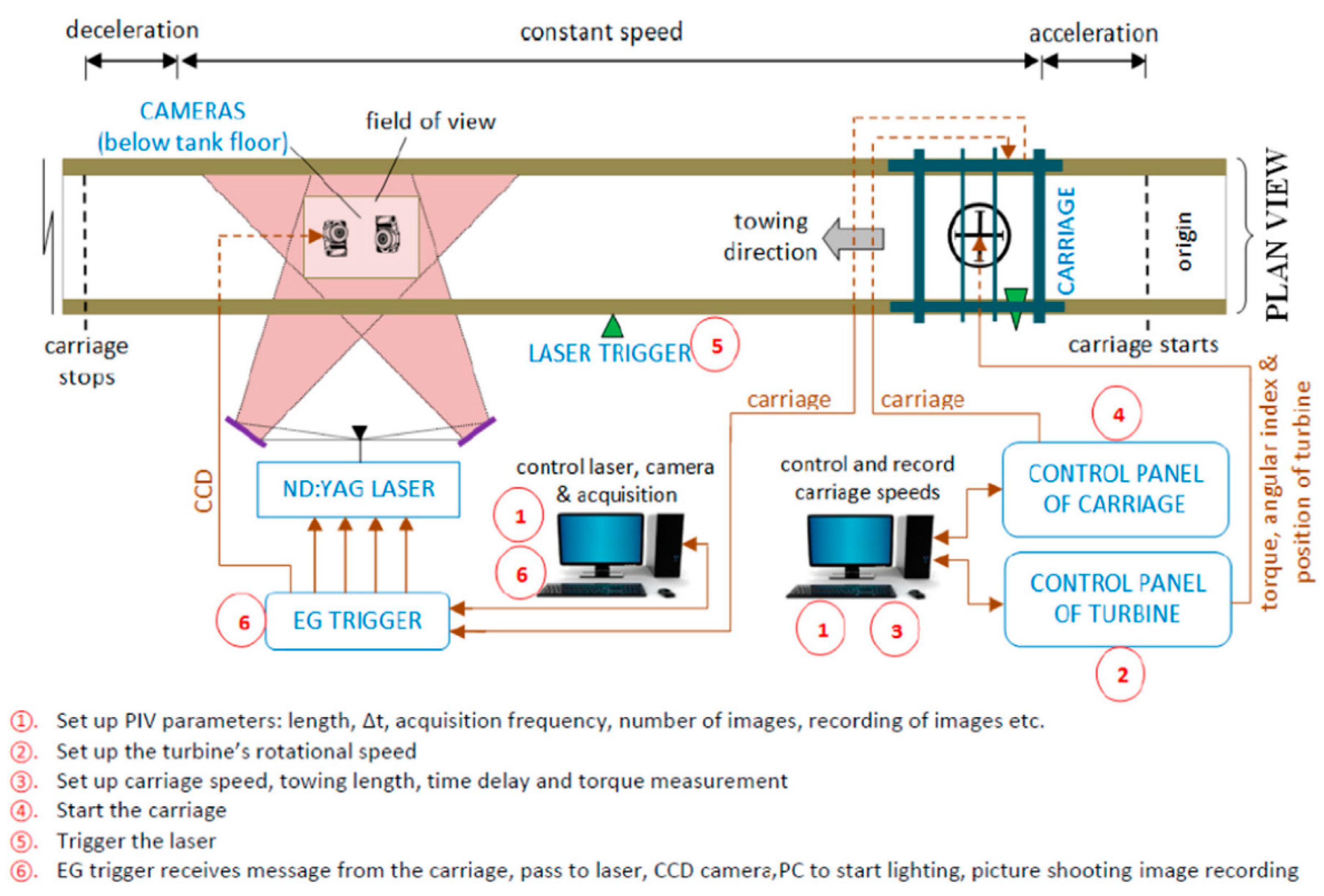
Gorle et al. [69] dragged the turbine with the drag system to measure the power and flow field at different angles, with the experimental setup shown in Figure 4. The experiment provided the relative velocity by the drag system, and the image acquisition section had a fixed distance from the starting section. The phase of the turbine was controlled by the initial phase at the starting section and the rotational speed.
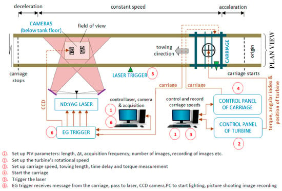
Figure 4.
Schematic of the experimental setup and data acquisition procedure [69].
Saini et al. [70] studied the mixed working characteristics of Savonius and Darrieus turbines. The flow rate in the passage was controlled between 0.15 m/s and 3 m/s. The flow rate was used to control the height of the water to keep the turbine immersed. The rotational speed of the turbine was measured by a digital tachometer, and the power of the turbine was evaluated at different rotational speeds by the controlled load on the turbine.
Bianchini et al. [71] conducted experiments to verify the two-dimensional numerical results. In the experimental design, the bracket movement was driven by permanent-magnet servomotor and synchronous belt, which can provide high-precision traction speed and was independently verified by a high-resolution linear encoder. The turbine was mounted in the trailer box via a dedicated support frame constructed from NACA0020 support rods and mounted to the sliding frame by linear bearings. The turbine shaft was loaded by a servomotor and gearbox to precisely control the average turbine TSR.
The flow speed was usually provided through pumping, water tanks with movable baffles provide controllable water height [72]. Towing provides relative velocity when the flow area is too big for pumping [73,74].
4. Geometric Parameters
4.1. Height-Diameter Ratio
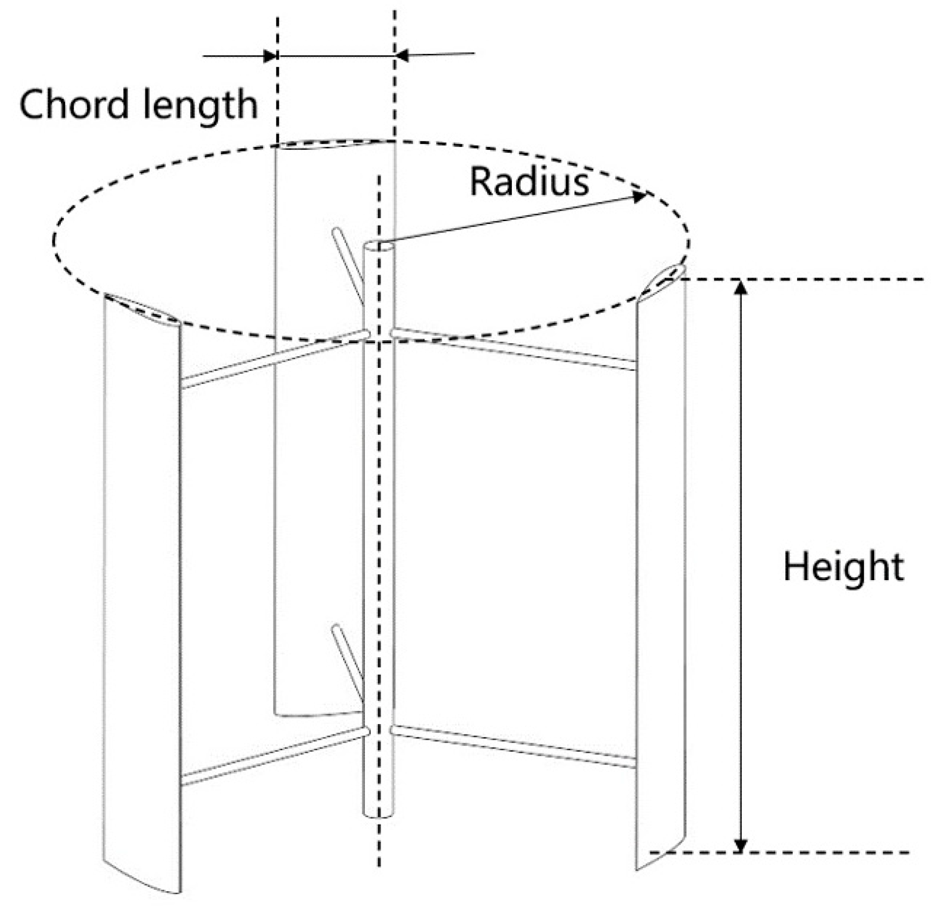
The main geometric parameters: turbine height, chord length, radius, and diameter were shown in Figure 5. Many optimization works were related to these geometric parameters.
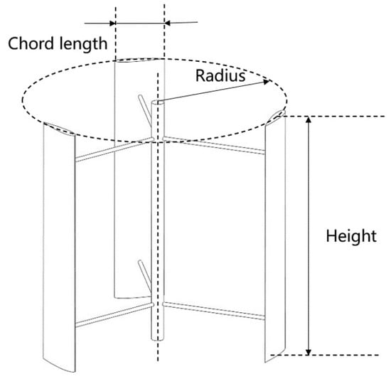
Figure 5.
Basic geometric parameters of Darrieus turbine.
The height–diameter ratio, or aspect ratio, is the ratio of the turbine height to the turbine diameter. The ideal turbine model has infinite shaft length and finite diameter, no gradient is present in the axial direction, and the turbine problem can be transformed into a two-dimensional problem. Complex three-dimensional flows at the ends of the blades reduce the performance of the turbine. Peng et al. [75] studied experimentally and found the power coefficient decreased with the height–diameter ratio. The suggested height–diameter ratio was equal to or above one for the vertical-axis wind turbines. Sengupta et al. [76] tested wind turbines with different height–diameter ratios experimentally and found the optimum height–diameter to be 1.0. But, the diameter was changed at the same chord length and height, and the decreased solidity contributed to the decrease in the power coefficient. Sengupta et al. [77] compared two-dimensional and three-dimensional results and suggested a height–diameter ratio of 1.0.
The increase of height–diameter ratio reduces the influence of three-dimensional flows and makes the results closer to those of two-dimensional turbines in numerical simulations. Li and Calisal [36], based on DVM-UBC calculation methods, performed numerical calculations for the three-dimensional effect with the height–diameter ratio as the variable. Correction methods based on the arm effect were proposed, which were in good agreement with the experimental results.
The results of height–diameter ratio showed that the three-dimensional effect was greatly significant when the height of the turbine is less than two times its radius and can be ignored when the height of the turbine is more than seven times its radius [78]. Two-dimensional calculations with correction for arm effects were more economical [71]; however, for special purposes, such as the calculation of vertical flow fluctuations, three-dimensional model calculations were still required.
4.2. Solidity
The solidity parameter is usually defined as the ratio of the total chord length to the turbine diameter [79,80]. The total chord length is calculated as the chord length multiplied by the blade number, the ratio can be the total chord length relative to the diameter, radius, or circular perimeter.
Patel et al. [81] conducted a numerical and experimental study on the effect of the chord length, turbine diameter, and hydrofoils on power coefficient at different TSRs. Results showed the maximal power coefficient appeared at a certain solidity.
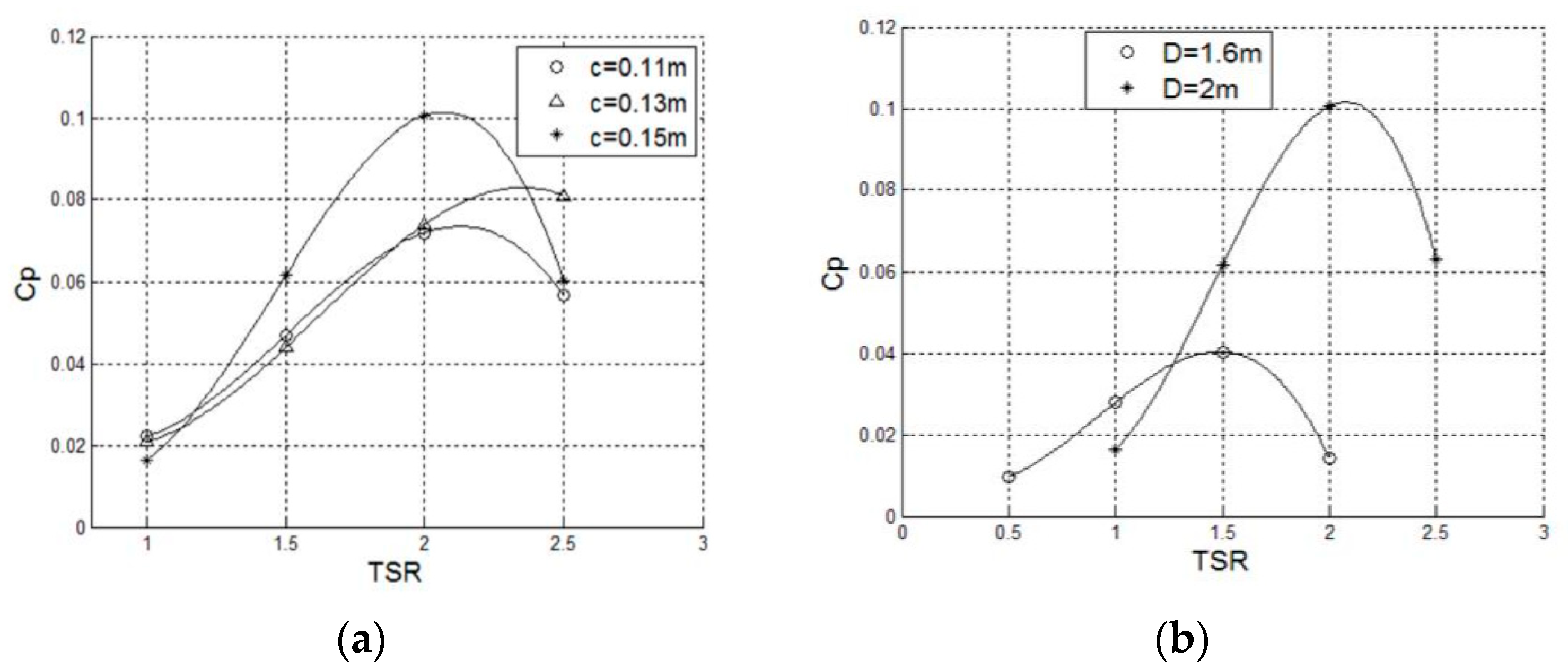
Wenlong et al. [82] simulated a Darrieus turbine on the mooring platform. The effects of structural parameters, including chord length and diameter, on turbine performance were investigated. The average Cm curve became lower and flatter as the blade chord length decreased. Blades with shorter chords have less interaction with the fluid, but long chords can strengthen blocking and reduce the power coefficient. Figure 6 shows the TSR curves with different chord lengths. The trends of the curves indicated that a turbine with a lower diameter will reach a maximum power at a lower TSR. As the turbine diameter increased, the solidity decreased, and the power coefficient reached its top at a higher TSR. In cases where the TSR is higher than 1.5, the turbine with a higher diameter generates a higher torque, leading to a higher power coefficient according to Equation (1).
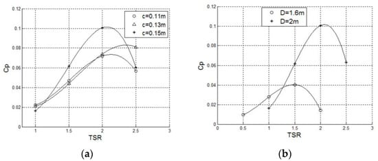
Figure 6.
(a) Cp-TSR curves with different chord length (b) Cp-TSR curves with different diameter [82].
The blade number has a great effect on the instantaneous torque. Under the same solidity, a single blade in a turbine with fewer blades provides a higher torque and rotates at a higher speed, and the torque fluctuations of the turbine are greater. A higher blade number at the same solidity can improve stability, but the structure needs to be reliable [83]. In the experiments of Patel et al. [81], turbines with three blades and four blades showed the same trend of power coefficient, first increasing and then decreasing with the solidity. The maximum power coefficient appeared at a solidity of 0.398 for the four-blade turbine, and the three-blade turbine had an optimized solidity of 0.382. The power coefficient after its peak drops quickly at a lower solidity, which may be caused by a low moment of inertia. An optimal solidity for a turbine can be expected, Table 1 shows that a solidity of 0.1 to 0.4 can provide the highest power coefficient.

Table 1.
Research of range of solidity.
The scale of the turbine is expected to be chosen according to the predicted power in the acceptable range. The power is usually predicted proportionate to cubic velocity and square length in wind turbine designs. The height–diameter ratio and the solidity can ensure geometrical similarity, and the TSR can maintain motion similarity. Some studies use the Strouhal number (Sr), and the Sr for Darrieus turbines can be simplified into the TSR. In a study [89], turbines with geometrical similarity and motion similarity showed the same power coefficient.
If the viscosity of water is considered by the Reynolds number, then the scale decreases with the increase of velocity, and the higher power can only be reached under a smaller scale and a higher velocity. Gravity also has a great influence on the similarity of Darrieus water turbines [90], and the effect is more significant in water turbines that are able to utilize pressure energy.
4.3. Torsion
The torques of straight-bladed Darrieus turbine change greatly with the angle. The torques at some angles are low, making the turbine hard to start up. After startup, the rotation speed fluctuation was also a major problem for Darrieus turbines. The blades can be spirally arranged in the circumferential direction or arranged in multiple staggered stages, so that there is always a part of the blade can provide high torque [91]. The helical turbine can start up easier and work with less fluctuation [92]. The Gorlov helical turbine [93] was developed by Professor Alexander M. Gorlov of Northeastern University in 1995. Gorlov and Mitsuhiro Shiono were the first to implement and work on prototypes. Golov tested his prototype at the Cape Cod Canal in Massachusetts, USA, between June and August 1996. Gorlov studied the performance of a triple-helical bladed turbine with a diameter of 24 inches (0.6096 m) and a height of 34 inches (0.8636 m). To stabilize the output, he introduced the NACA0020 hydrofoil with a chord of 7 inches (0.1778 m). The efficiency was 35%. The turbine reaches 100 rpm at 5 f/s (1.524 m/s).
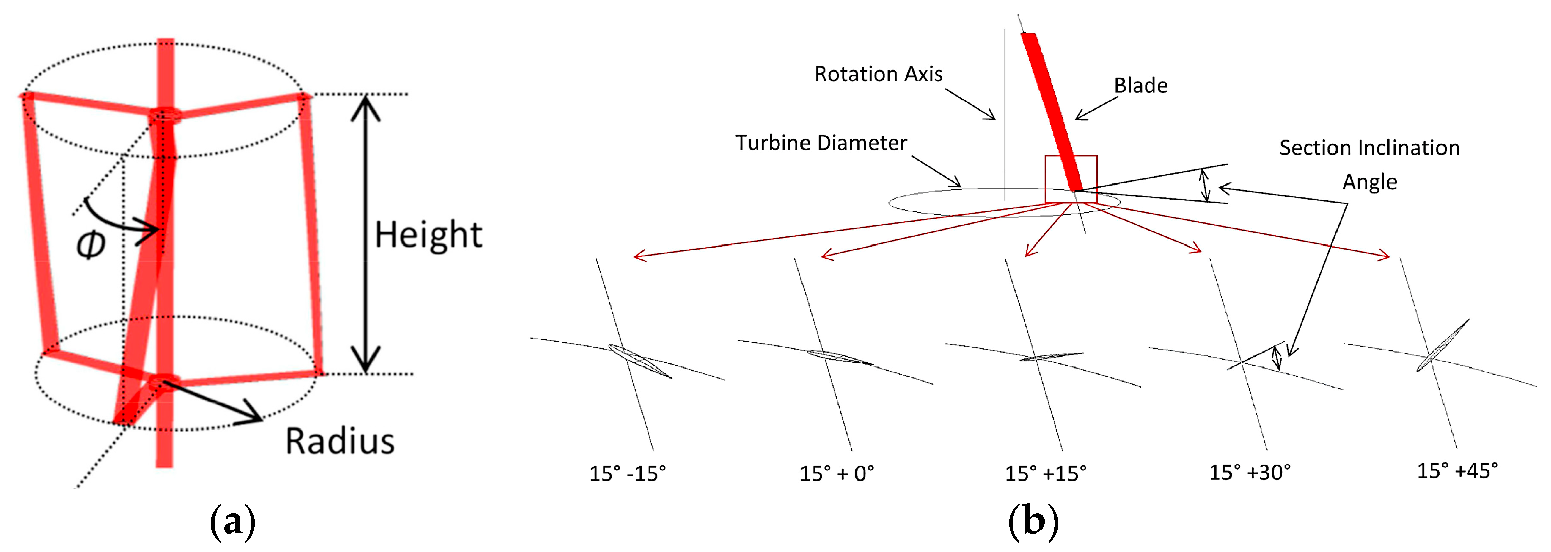
The torsion angle, as shown in Figure 7, was defined as the angle that a torsional blade covers. The blade was made along a helical line. Tilt straight blades were used to cover a range, but the attack angle was fixed and not good as the torsional blades [94,95,96]. Torsion for egg-shaped turbines was also developed as Troposkein turbines [97], the straight-blade turbine showed better in power output, but the Troposkein could take greater loads.
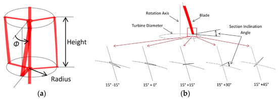
Figure 7.
(a) Definition of helical blade overlap angle (b) Definition of section inclination angle [98].
Pongduang et al. [84] studied the influence of different helical angles on the Darrieus turbine experimentally and numerically. The numerical results were basically consistent with the experimental results, and the turbine power values were compared. Three models with helical angles of 120°, 135°, and 150° were tested and simulated. Helical angles mainly affected the power output of the turbine, the output in the results decreased as the helical angle increased.
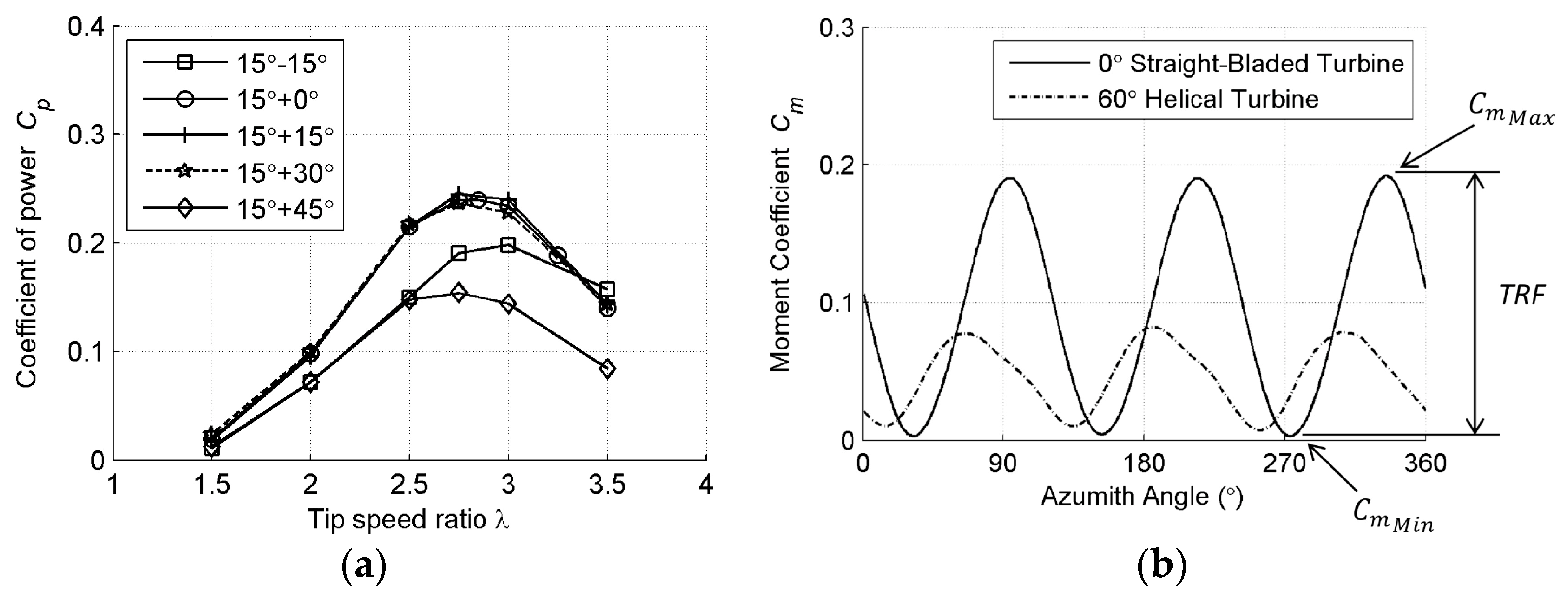
Marsh et al. [98] studied the effect of blade helicity. In addition to the helical anglethe angle of the blade layer relative to the original layer was also considered, which was called the inclination angle. The torque and power fluctuations decreased with the helical angle, and the starting ability increased. Turbines with different helical angles were compared, as shown in Figure 8b. The helical angle will lead to the loss of incoming flow energy in the wingspan flow and reduce energy utilization, and a larger helical angle will increase the loss. As the helical angle increased, the blades still primarily utilize the flow perpendicular to the blades, resulting in a reduction in the effective chord length of the blades. Therefore, the straight-blade turbine produces higher power output than the torsion turbine.
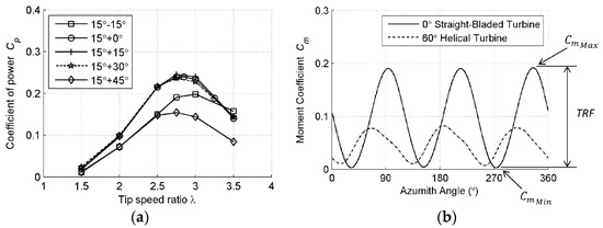
Figure 8.
(a) Cp curves of different inclination angles (b) Cm curves of different inclination angle [98].
In the comparisons of blade inclination angle, Figure 8a shows that the inclination angle actually had no significant effect on the performance of the turbine. It was believed that the alignment of the blade with the incoming flow is not critical if the blade is approximately perpendicular to the leading edge of the blade. As in Table 2, the torsional angle was always expected to be around 120°. In the reports with improved power coefficient through optimizing torsion, torsion was often optimized together with another geometric parameter. The increase in power coefficient may be the contribution of other geometric elements, and torsion itself seems to only provide a diversion in the span direction to reduce the power coefficient. Torsion improves turbine performance by reducing torque fluctuations and improving starting ability. Additional adjustments to the torsion structure can be a promising trend, and the wake structure with complex 3D effects deserves further discussion.

Table 2.
Research of turbine torsion.
4.4. Airfoil
The Darrieus turbine has to change directions and velocities, and the lift–drag characteristics of airfoils were not sufficient in the optimization of the blades. The dynamic stall of Darrieus turbine blades and interactions between flows of different blades need to be considered in the optimization of airfoils [101,102]. Symmetric hydrofoils such as NACA0018 were usually used for Darrieus water turbines, and NACA0015 was considered the best in turbine channels [103,104].
Mohamed et al. [105] studied the asymmetric and symmetric airfoils for vertical axis wind turbines numerically. Series including NACA 00XX, NACA63XX, S series, A series, and FX series were compared. It was found that turbines with symmetric airfoils have a wider range of TSR. The maximum power coefficient was reached by S-1045 and was relatively 26.83% higher than that of NACA0018. With the development of manufacturing, symmetric shows great potential in improving power output.
Yang and Shu et al. [67] optimized the airfoil by combining the traditional genetic algorithm with the layered fair competition model and parameterized the airfoil with the Bezier curve. Airfoils before and after optimization were studied numerically, and flow field results by PIV photography were compared with calculation. The max thickness was moved closer to the front, and the thickness decreased in the optimized airfoil. The lift coefficient of the optimized airfoil was greatly increased, and the drag coefficient remained low. The optimized turbine blades possessed superior hydrodynamic performance. The power coefficient was improved to 41.2%, and the fluctuation of torque and power output could be maintained at a low level. PIV visualization experiments helped compare the results of optimization. The concave curvature made the flow more stable, and the optimized blade recovered faster from the stall.
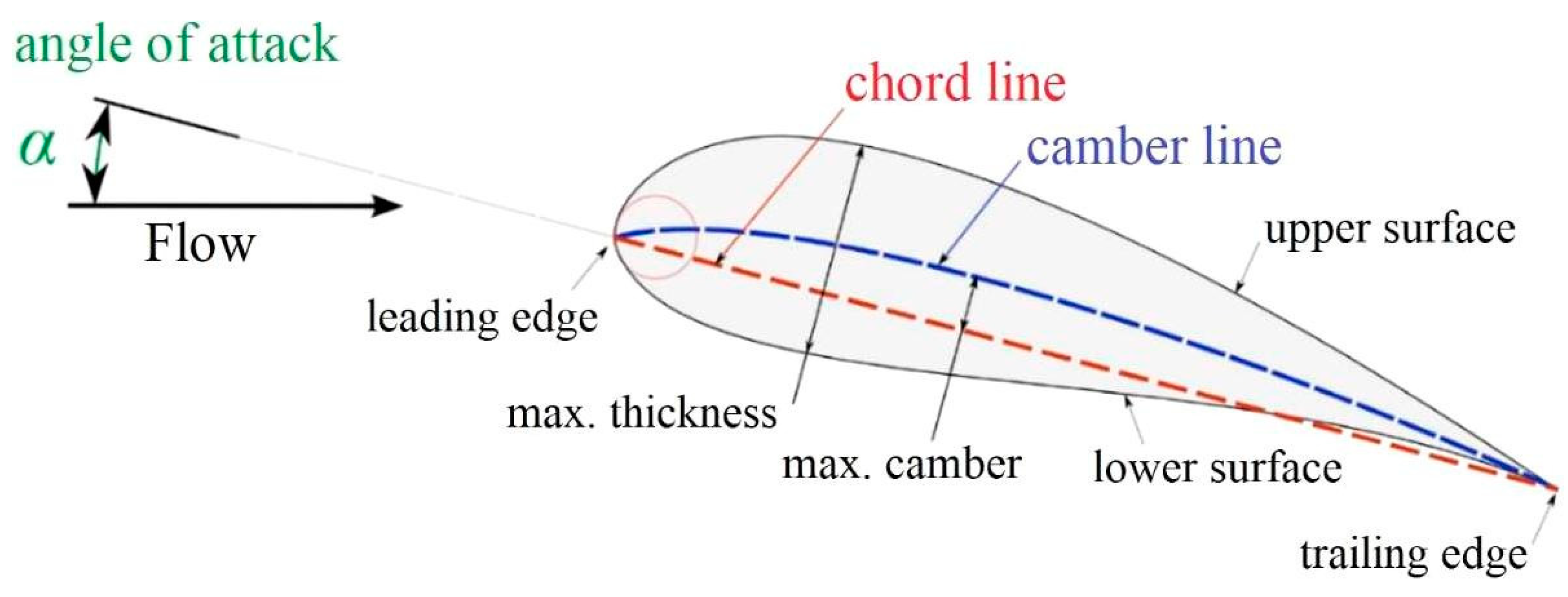
Khanjanpour and Javadi et al. [99] optimized the torsion angle, camber, position, maximum camber, and chord/radius ratio by using the Taguchi method. The Taguchi method was used to conduct a minimum number of experiments with a wide range of variables. The results of the Taguchi method gave a combination of factors in Figure 9 to bring maximum output. The optimized turbine had a power coefficient of 0.202 at a camber position of 0.2 and a maximum camber of 0.05, while the basic model had a power coefficient of 0.159. The chord/radius was reduced to 0.2 from 0.3. The results showed that the torsion angle was the most important of the four test factors and has the most significant effect on the turbine; the chord length/radius ratio has the least effect. The optimized reference airfoil was a symmetrical airfoil, and the optimized result was an asymmetric arc airfoil. The lift characteristics of the airfoil itself have been significantly improved, which can suppress dynamic stalls.
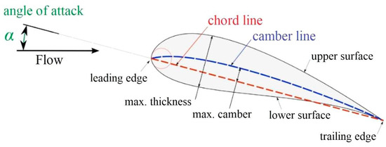
Figure 9.
Basic hydrofoil terminology [99].
Priegue and Stoesser [106] studied blade roughness to verify the assumption that blade roughness might delay flow separation to reduce the divergent velocity vortex. Rough blades in critical conditions were believed to potentially delay or weaken dynamic stall. Research results indicated that at low Reynolds numbers, rough blades, and smooth blades showed proximate torque. At high Reynolds, rough blades did not actually weaken dynamic stall but instead reduced the energy output of the rotor. The decrease became more evident at higher inflow velocities or higher rotational speeds corresponding to lower blade numbers.
Balduzzi et al. [107] attached Gurney Flap to the end of a two-stage Darrieus turbine and compared the performances with the smooth-blade turbine. The Gurney Flap was 2% chord length and had an inclination of 45°. The maximum instantaneous power coefficient of the turbine with Gurney Flap was greatly decreased. The lift was lowered at the upwind circle, and the lateral force on the central axis was reduced by about 50%.
It was generally believed that the key parameters in blade profile are chord, symmetry, thickness-chord ratio, and camber. As in Table 3, the optimizations were based on different parameters, and a common concept of methods to optimize the airfoil has not been reached. The optimizations aim to improve the average power coefficient, start-up, and stability.

Table 3.
Research of airfoil.
5. Methods to Improve Performance
5.1. Coupling with Savonius Turbines
The efficiency of the Darrieus turbine can reach the maximum limit of vertical-axis turbine, but has problems at start-up; the efficiency of the Savonius turbine was lower than of the Darrieus turbine, but the torque at start-up was great enough [108]. The Savonius turbine can be combined with the Darrieus turbine to provide start-up torque at a low speed, and the combined turbine can generate a larger lift force after starting [109,110]. The combined optimization was derived from a wind turbine. The Savonius turbine was usually placed inside the Darrieus turbine, which covered a smaller frontal area. Jahangir Alam and Iqbal [111] placed a double-stage Savonius turbine outside the four-blade Darrieus turbine and gained better self-starting behavior and lower efficiency compared with a single Darrieus turbine. As in Table 4, many efforts have been made to research the effects the ratio of diameters of the turbines and the relative angle in coupling.

Table 4.
Reports of coupled turbines.
Saini et al. [112] studied a two-blade Darrieus turbine combined with a two-blade Savonius turbine, and the numerical results were in good agreement with the experiments. The combined turbines at the 1 m/s incoming flow had a lower torque fluctuation. In the follow-up study [117], a three-blade Darrieus turbine was coupled with a two-blade Savonius turbine, and the parameters of the combination were considered, including radius ratio, relative angle, and relative height. The optimized parameters and the results were shown in Figure 10. The relative angle is the relative angular position of the two blades and the radius ratio represents the relative size. The relative height is the ratio of the heights of the Savonius turbine and the Darrieus turbine. The self-starting and efficiency were studied and showed that the maximum average torque coefficient of the mixed turbine was 0.1276 at a radius ratio of 0.6 and a relative angle of 90°. The mixed turbine had a reduced negative torque coefficient frequency. The maximum power coefficient of the mixed turbine was 37.97% higher than the power coefficient of a single turbine. The maximum average torque coefficient was increased by 35.88%.

Figure 10.
(a) Geometric characters of combined Darrieus-Savonius turbine [112]. (b) Cp-TSR curves of single Darrieus and coupled turbine. (c) Ct-azimuth angle curves [70].
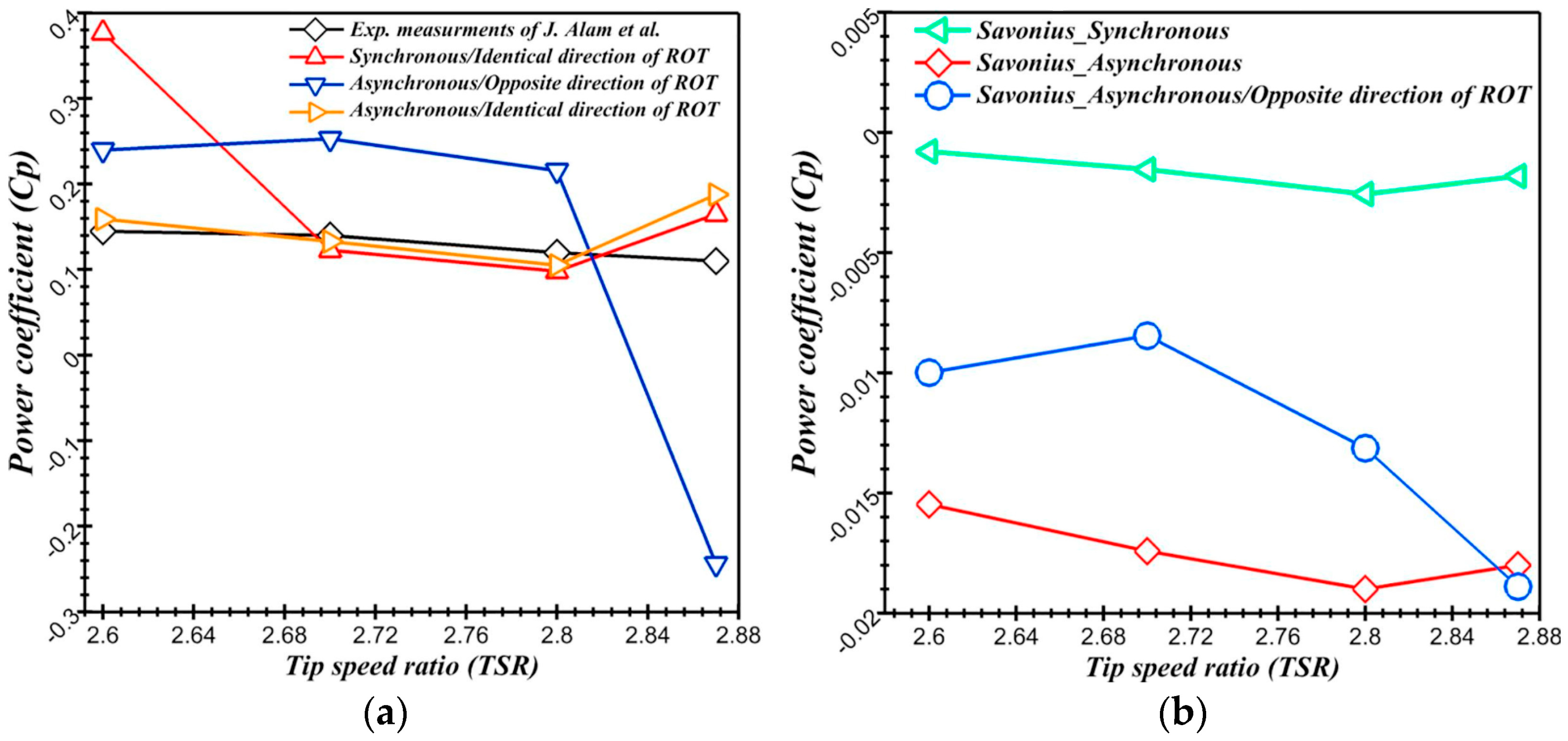
Ed-Dn Fertahi et al. [113] focused on the performance of the combined turbine. A four-blade Darrieus turbine was coupled with a double-stage Savonius turbine. Synchronously and asynchronously coupling were compared, and the rotational directions were considered. As shown in Figure 11, asynchronous coupling (same rotational direction) provided the best performance. In asynchronous coupling, the Savonius turbine in the low-speed range can provide a significant starting torque. After the startup, the performances of the Savonius and Darrieus turbines in asynchronous coupling were closer to the optimum speed compared to synchronous coupling. The numerical results showed that the optimized range of TSR has to be considered in coupling.
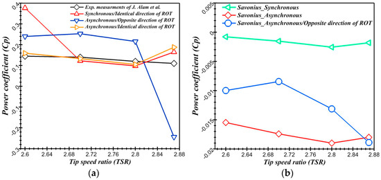
Figure 11.
(a) Cp curves of coupled turbine. (b) Cp curves of Savonius turbine [113].
Coupling with other turbines could also improve the starting ability [118], but the highest power coefficient of the coupled turbine needs further improvement. The goal of coupling was to drive the Darrieus turbine in start-up, and the Darrieus turbine can provide higher efficiency at a higher rotation speed after starting. The two-stage Savonius was more stable and easier to start, which makes it more suitable for asynchronous coupling with Darrieus turbine. Synchronous coupling should make up the low torque of the Darrieus turbine at some angle, so that a single-stage Savonius turbine at a certain relative angle was better.
5.2. Blade Pitching
The pitch angle of fixed-pitch Darrieus turbines is important, as it affects the attack angle and the contribution of radical and axial forces to the torque [119,120]. The attaching angles of blades can be optimized to improve the torque output [56]. The Darrieus turbine can delay stall and maintain a good attack angle by tilting the blades periodically, and the process is called pitching [121]. In the process of pitching, the optimal pitch angle should be a function of blade azimuth position and TSR [122]. The pitch was usually divided into two categories. In active pitch or forced pitch, the blades are forced to pitch in a predetermined way [123]. In passive pitch or self-acting pitch, the blades are free to pitch and stabilize the torque under the interaction between hydrodynamic and inertial forces [124]. The instantaneous pitch angle can be controlled in active pitching while in passive pitching the pitch angle changes with the flow. Active pitching is able to optimize every actual position while passive pitching can only control the range of pitch angle, so active pitching shows more potential in performance. Pitching can also reduce cavitation, which can improve the life of the turbine [52].
Benzerdjeb et al. [125] conducted experiments on blade pitch angles and found a 67% increase at a blade pitch angle of 1.75°. The passive pitching angle showed great influence on the torque arm.
Chen et al. [126] studied the active pitch in a sinusoidal form numerically. The changes in power coefficient, torque coefficient, and fluctuation coefficient were analyzed. The benefit of pitch control was obtained mainly in the upstream half cycle of the blade path, which delayed the stall. As a result of the high local TSR in the downstream half cycle, a high pitch amplitude results in a resistive torque that cancels out the gains made in the upstream half cycle. The optimum amplitude of the sinusoidal pitch change of a turbine was 5°–10° under test conditions. In a variable-pitch turbine, both radial and axial forces contribute to the torque. Later, Chen et al. [127] studied a simple modification of the sinusoidal pitch variation to eliminate the downstream pitch to reduce the drag torque due to excessive pitch in the downstream half cycle of the blade flight path. The new pitch function improved the stability and the power output. The torque and rotational speed of the optimized pitch turbine were about 70% of those of the sinusoidal pitch turbine. At high TSRs, the power coefficient of sine-pitch turbines was reduced to the same level as fixed-pitch turbines, while the optimized pitch turbine retained a high-power coefficient.
Paillard et al. [128] studied the sinusoidal form of active pitch to optimize power generation and reduce radial forces. The TSR of the variable pitch was five, and the main optimization purpose was to improve the performance. Sinusoidal functions with different parameters were tested. The second harmonic function improved the power coefficient by 52%. The incident angle of the upstream part was reduced, and the attack angle of the downstream part was increased. The optimized turbine showed better starting ability and stability.
Melani et al. [129] proposed a double-cam active pitching system, which can provide a more flexible pitch law. A primary pitch law was given according to the lift–drag curve of the blade. The law was later optimized using Actuator Line Method. CFD simulations were set to confirm the results of the optimizations. The optimum power coefficient was 0.54, with an increase of 37% compared with the baseline model. The double-cam active pitching system was promising for active pitching for its ability to the realization of optimized pitch law.
Zhang et al. [130] studied the Darrieus passive pitch numerically and experimentally. The research obtained the ideal swing angle range and found the relationship between the pitch angle range and the turbine power coefficient. The start-up of the passive pitch turbine was improved, and the pitch angle range affected the power output and structural characteristics. The optimization of pitch angle reduced the interaction between blades and vortex and improved the power output.
Flexible blades [131] can passively change their shape and attack angle with the incoming to perform appropriate passive pitch and recover through elasticity. Zeiner-Gundersen et al. [89,132] studied the flexible blade through numerical and experimental investigations on the flexible-blade turbine and found that the performance stability was improved. The flexible blades reduced the maximum torque and stabilized the power output, having higher power coefficients at lower TSRs than fixed-blade turbines.
Hoerner et al. [133] also studied highly flexible blade foils and found that the highly flexible blades were simpler in structure and had a longer lifetime. Fluid-structure interaction research on flexible blades was conducted by Brusca et al. [85] and showed that the flexibility decreased the fluctuation of the radial and circumferential forces, and the lift force was increased.
The gain in blade pitching was greater for turbines with higher solidity and operating at lower TSRs [124]. Table 5 shows that sinusoidal functions and optimized sinusoidal functions can greatly improve the power coefficient, reduce fluctuation, and help start-up. Passive pitching requires fewer mechanical parts and has no requirement for a fixed direction of inlet flow. At a relatively certain flow direction, the parameterized model of the active pitch control strategy and its further optimization can be a future research direction. At inlet flow from multiple directions, the impact of passive pitch control damping on instantaneous pitch angle and turbine performance deserves further research.

Table 5.
Research of blade pitching.
5.3. Multi-Turbine Arrangement
In application, the turbines will be placed in multiple arrangements. The geometric structure and distances of the arrangement can affect the interaction among turbines [136].
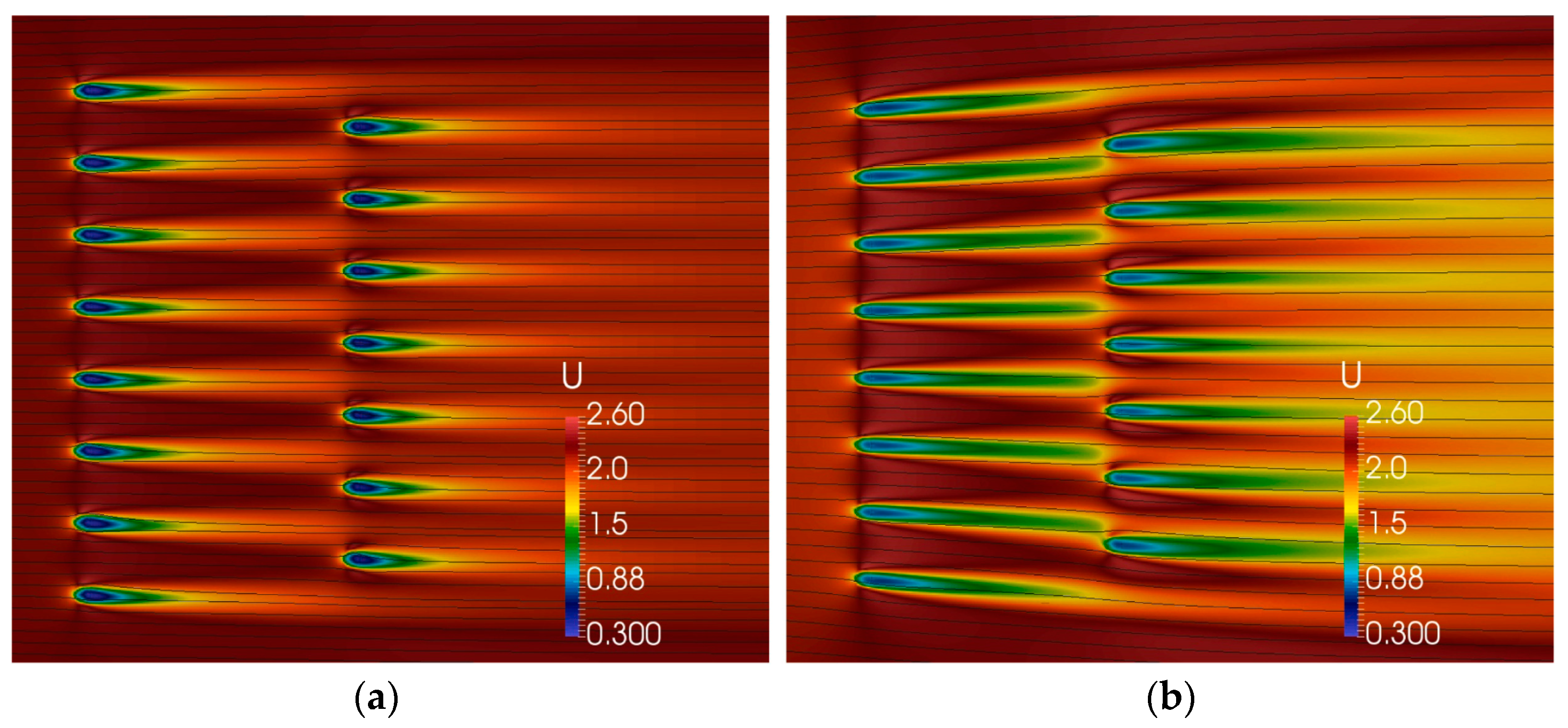
Clary et al. [35] conducted a numerical simulation on the horizontal arrangement of the Darrieus turbines in a river, in which the spacing in the same row and the spacing between rows were adjusted. The simulation results show that the performance of the turbine improved by 24% when the spacing of the horizontal rows was 1.2D. The three-dimensional numerical model can also simulate the wake flow between 4D and 6D. A similar calculation was performed using a two-dimensional model. As in Figure 12, they analyzed flow fields of different arrangements in the two-dimensional or three-dimensional model. However, the author believes that the two-dimensional model has a large error in the calculation of the output. Therefore, the three-dimensional model should be used in the array calculation.
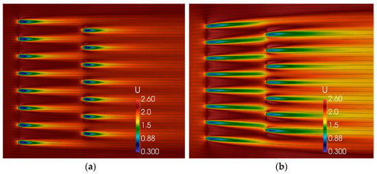
Figure 12.
(a) 2D Velocity colormap and streamlines (b) 3D Velocity colormap and streamlines [35].
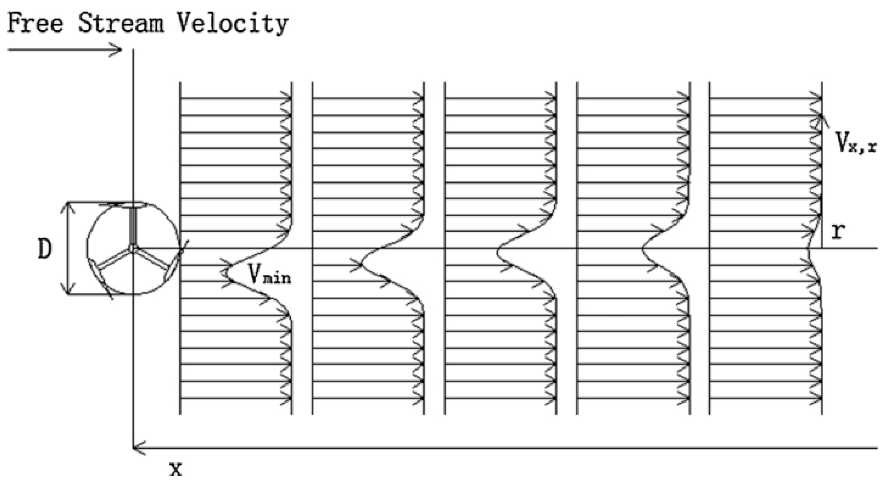
Ma et al. [137] used axial momentum theory and numerical simulation to simulate the Darrieus turbine and further proposed a theoretical equation that can predict the wake velocity of vertical-axis turbine. Based on the axial momentum theory, the equation originally used for the horizontal axis turbine was extended, and the velocity distribution at different distances of the Darrieus turbine wake was deduced and predicted. A comparison of the theoretical results with the experimental results shows that the velocity error was within 1.13%. As in Figure 13, the theory considered the turbine asymmetric, and the distance of arrangement along the inflow direction can be inspired by the trend of wake recovery.
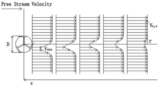
Figure 13.
Wake profile along the downstream direction by using the lateral velocity distribution equation [137].
Li and Calal [138] studied a double-turbine system. Numerical results showed that the relative efficiency of the double-turbine system was 25% higher than that of the single turbine, while the efficiency was 35% lower than twice that of the single turbine. The power output of the system was less than twice the power of an independent turbine.
Crooks and J.M. et al. [139] discussed the power generation structure of a series-connected motor structure based on experimental and numerical methods. The upper and lower rotors drive permanent magnets and coils, respectively, generating power by rotating in opposite directions and forming a dual rotor system in conjunction with another set of rotors. The results indicated that the dual rotor system created a high-speed region between the rotors, resulting in an improved power coefficient compared to a single rotor system and reduced instantaneous power fluctuations. Additionally, the structure of reverse rotation and dual-rotor structure may also enhance the startup ability.
Zanforlin [140] performed a computational fluid dynamics (CFD) analysis of three closely adjacent vertical-axis tidal turbines for a linear layout and a triangular layout. Turbine blockage was effective in accelerating flow inside the passageway between adjacent turbines. Changes in incoming flow direction became more favorable to the blade. The wake contraction increased the torques of the upstream blades. Blockage caused performance improvement in triangular layouts. In the side-by-side layout, the flow direction changing resulted in wake contraction, and the efficiency significantly increased. The in-line layout is suitable for many flow directions with extra power improvement. After testing in Energy yield, the linear layout provided about two times relative gain compared with that from the triangular layout. The linear layout performs better, and the triangular has better stability of arrangement.
In Table 6, the distance in linear arrangements was the optimization object. The rotational direction between turbines in multi-turbine arrangement has a great influence on the efficiency. Helical turbines could also be arranged in multiple structures [141]. The interactions between turbines were mainly caused by blockage and asymmetric flows.

Table 6.
Research of multi turbine arrangement.
5.4. Additional Devices
Tidal energy has great potential, yet the speed is low, and starting the turbines can be difficult [143]. Additional devices were considered a way to improve the starting and the efficiency. Inlet nozzles [144,145] and ducted tunnels [146,147] can provide local acceleration and pressure energy, and the efficiency can be higher than the Betz limit because of the pressure energy. Devices at the rotor of the generator revolution, including starting assist mechanism, were considered to improve starting and efficiency [148,149,150]. Table 7 shows some researches improving the efficiency with additional devices.

Table 7.
Research of additional devices.
Santiago et al. [156] conducted numerical studies to decrease outlet vortex with additional tiny blades at the edges of the original blades. The effective blade length was increased and provided higher power. But, the winglets have large complexity in manufacture and may be not profitable.
Liu et al. [153] carried out comparisons numerically and experimentally on turbines working in bare configuration or ducted with two-foiled channel devices. NACA11414 and EPPLER420 were used as the channel shape. Different angles of the channel foils were used, and the torque in the whole circle was greatly improved.
Malipeddi and Chatterjee [157] optimized the shape of the duct. The torque fluctuation was great and the power coefficient was increased from 0.40 to 0.63. The thinnest place of the duct was suggested to place the turbine, and the straight external shaped duct showed better performance than the convex external shaped duct.
A guide vane optimization analysis was conducted in the work of A. M. Roa et al. [158]. The augmented turbine showed a higher power coefficient at the ideal TSR, and the fluctuations of power output decreased. The chord length of the guide vane was suggested to be the same as that of the turbine blade, and the gap between the guide vane and the turbine was suggested to be a quarter of the chord length. The pitch angle of the guide vane was suggested as zero. The structure also utilized local acceleration, but the circular symmetry kept the advantage of vertical-axis turbines.
An accelerator device was studied by Fernandez-Jimenez et al. [159] numerically and experimentally. The inlet width was decreased from 0.65 m to 0.39 m, and the blockage was found to greatly improve the power coefficient. The maximum power coefficient at non-restricted conditions was 0.29, and the power coefficient reached 1.91 at confined flow conditions. The -TSR curve of the open-field tests showed similar trends at different heights, while the and TSR of confined tests increase with the height. The utilization of pressure energy may contribute to the difference.
6. Conclusions
For a Darrieus water turbine, the ability to start up to an optimal speed is crucial for its application, especially under low flow speed conditions. Darrieus turbines in water also require higher operational stability to achieve a longer operating lifespan. The applicable TSR and its corresponding Cp for Darrieus water turbines need further summarization. Existing research methods, geometric configurations, and performance optimizations for Darrieus water turbines have achieved certain results, with a focus on starting capability, operational stability, and power output. In the following discussion, the key points of existing research will be summarized.
(1) Research methods of the Darrieus turbine were summarized. BEM can predict dynamic stall with experimental correction and can effectively evaluate design parameters. The RANS simulation can predict dynamic stall relatively precisely. The k-ω SST model can simulate the vortexes during dynamic stall at low TSR better than the k-ω and k-𝜖 models due to its high adverse pressure gradients and smooth surface separations. LES and DES methods can obtain better results in simulating dynamic stall and vortex structures, but they need much more computation than RANS. A fixed rotation speed of the turbine was given in many simulations. Recently, simulations regarding variations in instantaneous rotation speeds have become a trend. With appropriate research methods, research on geometric parameters and optimization methods of the Darrieus turbines can be improved.
(2) The geometric parameters were summarized to guide the design of the Darrieus water turbine. The scale should be chosen according to the flow speed and expected power and TSR. The three-dimensional effect was significant at a height-diameter ratio below 1.0 and can be ignored at a height–diameter ratio over 3.5. The height–diameter ratio was suggested to be over 1.0. The increase of solidity reduces the TSR of maximal power, and an ideal solidity of 0.1 to 0.4 exists for the turbine to reach the highest power coefficient. Symmetric airfoils such as NACA0018 and NACA0015 were frequently used for their ability to provide lift force at different attack angles, and the NACA0015 has the best performance in ducted sections. Asymmetric airfoils with optimized camber can improve the lift force and moving the maximum thickness closer to the front can improve the lift–drag ratio. A design method for Darrieus turbines based on empirical results of TSR and Cp to get geometric parameters is expected to be proposed. Considering the high density and incompressibility of water as the medium, further discussions of similarity parameters for the Darrieus water turbines can be a future research direction. The torsional turbine can significantly enhance startup ability and stability, but it leads to a significant reduction in power. Further research prospects lie in the following directions: additional adjustments to the geometry of the torsion, and further discussion into the complex three-dimensional wake structures of torsional turbines.
(3) Many methods were adopted to further improve the efficiency, stability and starting ability of the Darrieus turbine. Co-directional coupling of the Savonius and Darrieus turbine to match their rotation speed is considered to improve their working condition. The double-stage Savonius turbine worked more stable and was suitable for asynchronous coupling, and the single-stage Savonius turbine can better make up the low peak of the Darrieus turbine torque. The sinusoidal pitching greatly improves the power coefficient, reduces fluctuation, and helps start-up. A given pitching law can be realized with the double-cam active pitching system, and the optimizations of the pitching law are a new trend. Flexible blades reduce the instantaneous force and more reliable materials are expected. The asymmetry of turbine wake shows potential in improving the efficiency of the downstream turbine, and the three-dimension structure of helical turbines deserves further research. The linear arrangement shows better power output, while the triangular arrangement has more stability of arrangement, and the rotational direction should be well arranged.
Author Contributions
Investigation, G.L. and G.W.; Writing—Original Draft, G.L.; Writing—Review and Editing, G.W., H.F. and L.T. All authors have read and agreed to the published version of the manuscript.
Funding
This article is supported by funding from the National Natural Science Foundation of China (Grant No. 51879140), State Key Laboratory of Hydroscience and Hydraulic Engineering (Grant No. 2021-KY-04), Tsinghua-Foshan Innovation Special Fund (Grant No. 2021THFS0209), and Creative Seed Fund of Shanxi Research Institute for Clean Energy, Tsinghua University.
Institutional Review Board Statement
The study did not require ethical approval.
Informed Consent Statement
This research did not include any study involving humans.
Data Availability Statement
No new data were created or analyzed in this study. Data sharing is not applicable to this article.
Conflicts of Interest
The authors declare no conflict of interest.
References
- Nachtane, M.; Tarfaoui, M.; Goda, I.; Rouway, M. A review on the technologies, design considerations and numerical models of tidal current turbines. Renew. Energy 2020, 157, 1274–1288. [Google Scholar] [CrossRef]
- Singal, R.K. Floating type micro hydro power plants. Electr. India 1984, 24, 21–25. [Google Scholar]
- Hand, B.; Cashman, A. A review on the historical development of the lift-type vertical axis wind turbine: From onshore to offshore floating application. Sustain. Energy Technol. Assess. 2020, 38, 100646. [Google Scholar] [CrossRef]
- Lei, H.; Su, J.; Bao, Y.; Chen, Y.; Han, Z.; Zhou, D. Investigation of wake characteristics for the offshore floating vertical axis wind turbines in pitch and surge motions of platforms. Energy 2018, 166, 471–489. [Google Scholar] [CrossRef]
- Thomson, K.D. Power generation from the east australian current by use of arrays of submerged darrieus vertical axis turbines. In Proceedings of the 7th Australasian Conference on Hydraulics and Fluid Mechanics, Brisbane, QLD, Australia, 18–22 August 1980; Preprints of Papers. pp. 35–38. [Google Scholar]
- Furukawa, A.; Gajanayake, P.A.; Okuma, K.; Tagaki, A. Basic Study of Low Head Water Power Utilization by Using Darrieus-Type Turbine; Memoirs of the Kyushu University, Faculty of Engineering: Fukuoka, Japan, 1998; Volume 58, pp. 39–53. [Google Scholar]
- Furukawa, A.; Seo, N.; Okuma, K.; Takamatsu, Y. Operating Characteristics of Darrieus-Type Cross-Flow Water Turbine and Numerical Simulations for Self-Starting Process. Trans. Jpn. Soc. Mech. Eng. Ser. B 1994, 60, 2466–2471. [Google Scholar] [CrossRef]
- Khan, M.; Bhuyan, G.; Iqbal, M.; Quaicoe, J. Hydrokinetic energy conversion systems and assessment of horizontal and vertical axis turbines for river and tidal applications: A technology status review. Appl. Energy 2009, 86, 1823–1835. [Google Scholar] [CrossRef]
- Zheng, J.; Dai, P.; Zhang, J. Tidal stream energy in China. Procedia Eng. 2015, 116, 880–887. [Google Scholar] [CrossRef]
- Wang, J.N.; Wang, F.; Zhang, L.L. Construction and operation of a deep-sea scientific observation network in the western pacific. Oceanol. Limnol. Sin. 2017, 48, 1471–1479. [Google Scholar]
- Li, Y.; Calisal, S.M. Modeling of twin-turbine systems with vertical axis tidal current turbine: Part II—Torque fluctuation. Ocean Eng. 2011, 38, 550–558. [Google Scholar] [CrossRef]
- Han, S.-H.; Park, J.-S.; Lee, K.-S.; Park, W.-S.; Yi, J.-H. Evaluation of vertical axis turbine characteristics for tidal current power plant based on in situ experiment. Ocean Eng. 2013, 65, 83–89. [Google Scholar] [CrossRef]
- Sun, C.; Lam, W.-H.; Lam, S.S.; Dai, M.; Hamill, G. Temporal Evolution of Seabed Scour Induced by Darrieus-Type Tidal Current Turbine. Water 2019, 11, 896. [Google Scholar] [CrossRef]
- Sun, C.; Lam, W.H.; Cui, Y.; Zhang, T.; Jiang, J.; Guo, J.; Ma, Y.; Wang, S.; Tan, T.H.; Chuah, J.H.; et al. Empirical model for Darrieus-type tidal current turbine induced seabed scour. Energy Convers. Manag. 2018, 171, 478–490. [Google Scholar] [CrossRef]
- Furukawa, A.; Takamatsu, Y.; Okuma, K.; Takenouchi, K. Optimum Design of the Darrieus-Type Cross Flow Water Turbine for Low Head Water Power. Renew. Energy Technol. Environ. 1992, 2824–2828. [Google Scholar] [CrossRef]
- Torresi, M.; Fortunato, B.; Camporeale, S.M. Numerical Investigation of a Darrieus Rotor for Low-head Hydropower Generation. Procedia Comput. Sci. 2013, 19, 728–735. [Google Scholar] [CrossRef]
- Antheaume, S.; Maître, T.; Achard, J.-L. Hydraulic Darrieus turbines efficiency for free fluid flow conditions versus power farms conditions. Renew. Energy 2008, 33, 2186–2198. [Google Scholar] [CrossRef]
- Agus, M.; Titik, N. Simulation model of darrieus turbine using software CFD (Computating Fluid Dinamyc) in Bedono Village of Demak District. J. Phys. Conf. Ser. 2018, 1025, 012018. [Google Scholar]
- Zhao, Y.; Cao, Y.; Wang, S.; Ge, L.; Liu, Z. Failure analysis on darrieus type cross-flow water turbines under environment load on sea. In Proceedings of the 29th International Ocean and Polar Engineering Conference, ISOPE 2019, Honolulu, HI, USA, 16–21 June 2019; Volume 1, pp. 202–208. [Google Scholar]
- Aumelas, V.; Pellone, C.; Maître, T. Cavitating behaviour analysis of Darrieus-type cross flow water turbines. IOP Conf. Series: Earth Environ. Sci. 2010, 12, 012077. [Google Scholar] [CrossRef]
- Maldar, N.R.; Ng, C.Y.; Oguz, E. A review of the optimization studies for Savonius turbine considering hydrokinetic applications. Energy Convers. Manag. 2020, 226, 113495. [Google Scholar] [CrossRef]
- Kirke, B. Tests on ducted and bare helical and straight blade Darrieus hydrokinetic turbines. Renew. Energy 2011, 36, 3013–3022. [Google Scholar] [CrossRef]
- Derakhshan, S.; Ashoori, M.; Salemi, A. Experimental and numerical study of a vertical axis tidal turbine performance. Ocean Eng. 2017, 137, 59–67. [Google Scholar] [CrossRef]
- Qian, P.; Feng, B.; Liu, H.; Tian, X.; Si, Y.; Zhang, D. Review on configuration and control methods of tidal current turbines. Renew. Sustain. Energy Rev. 2019, 108, 125–139. [Google Scholar] [CrossRef]
- Liu, K.; Yu, M.; Zhu, W. Performance analysis of vertical axis water turbines under single-phase water and two-phase open channel flow conditions. Ocean Eng. 2021, 238, 109769. [Google Scholar] [CrossRef]
- Le Hocine, A.E.B.; Poncet, S.; Lacey, J. Numerical Modeling of a Darrieus Horizontal Axis Shallow-Water Turbine. J. Energy Eng. 2020, 146, 04020050. [Google Scholar] [CrossRef]
- Fleisinger, M.; Vesenjak, M.; Hriberek, M. Flow driven analysis of a darrieus water turbine. Stroj. Vestn./J. Mech. Eng. 2014, 60, 769–776. [Google Scholar] [CrossRef]
- Le Hocine, A.E.B.; Lacey, R.J.; Poncet, S. Multiphase modeling of the free surface flow through a Darrieus horizontal axis shallow-water turbine. Renew. Energy 2019, 143, 1890–1901. [Google Scholar] [CrossRef]
- Mosbahi, M.; Ayadi, A.; Chouaibi, Y.; Driss, Z.; Tucciarelli, T. Performance improvement of a novel combined water turbine. Energy Convers. Manag. 2020, 205, 112473. [Google Scholar] [CrossRef]
- Gorlov, A.M. Extracting energy from ocean waves and currents using the helical turbine. In Proceedings of the 1998 17th International Conference on Offshore Mechanics and Arctic Engineering, OMAE, Lisbon, Portugal, 5–9 July 1998; p. 8. [Google Scholar]
- Khan, M.J.; Iqbal, M.T.; Quaicoe, J.E. A technology review and simulation based performance analysis of river current turbine systems. In Proceedings of the 2006 Canadian Conference on Electrical and Computer Engineering, CCECE’06, Ottawa, ON, Canada, 7–10 May 2006; pp. 2288–2293. [Google Scholar]
- Kirke, B. Hydrokinetic turbines for moderate sized rivers. Energy Sustain. Dev. 2020, 58, 182–195. [Google Scholar] [CrossRef]
- Takamatsu, Y.; Furukawa, A.; Okuma, K.; Shimogawa, Y. Study on Hydrodynamic Performance of Darrieus-type Cross-flow Water Turbine. Bull. JSME 1985, 28, 1119–1127. [Google Scholar] [CrossRef]
- Shiono, M.; Suzuki, K.; Kiho, S. Experiments on the characteristics of darrieus turbine for the tidal power generation. In Proceedings of the International Offshore and Polar Engineering Conference, Brest, France, 30 May–4 June 1999; Volume 1, pp. 123–128. [Google Scholar]
- Clary, V.; Oudart, T.; Larroudé, P.; Sommeria, J.; Maître, T. An optimally-controlled RANS Actuator force model for efficient computations of tidal turbine arrays. Ocean Eng. 2020, 212, 107677. [Google Scholar] [CrossRef]
- Li, Y.; Calisal, S.M. Three-dimensional effects and arm effects on modeling a vertical axis tidal current turbine. Renew. Energy 2010, 35, 2325–2334. [Google Scholar] [CrossRef]
- Zanforlin, S.; Burchi, F.; Bitossi, N. Hydrodynamic Interactions Between Three Closely-spaced Vertical Axis Tidal Turbines. Energy Procedia 2016, 101, 520–527. [Google Scholar] [CrossRef]
- Zhen, L.; Hengliang, Q.; Hongda, S. Numerical study on self-starting performance of darrieus vertical axis turbine for tidal stream energy conversion. Energies 2016, 9, 789. [Google Scholar]
- Li, Y.; Çalial, S.M. Numerical analysis of the characteristics of vertical axis tidal current turbines. Renew. Energy 2010, 35, 435–442. [Google Scholar] [CrossRef]
- Guillaud, N.; Balarac, G.; Goncalvès, E.; Zanette, J. Large Eddy Simulations on Vertical Axis Hydrokinetic Turbines—Power coefficient analysis for various solidities. Renew. Energy 2019, 147, 473–486. [Google Scholar] [CrossRef]
- Takamatsu, Y.; Furukawa, A.; Takenouchi, K.; Okuma, K. Experimental Considerations in an Approximate Method for Estimating the Blade Performance of Darrieus-Type Cross-Flow Water Turbines. JSME Int. J. Ser. B 1993, 36, 135–142. [Google Scholar] [CrossRef]
- Furukawa, A.; Takamatsu, Y.; Takenouchi, K. Theoretical considerations in an approximate method for estimating the blade performance of a Darrieus-type cross-flow water turbine. Trans. Jpn. Soc. Mech. Eng. Ser. B 1987, 53, 2507–2513. [Google Scholar] [CrossRef]
- Takamatsu, Y.; Furukawa, A.; Okuma, K.; Takenouchi, K. Experimental studies on a preferable blade profile for high efficiency and the blade characteristics of darrieus-type cross-flow water turbines. JSME Int. J. Ser. 2 Fluids Eng. Heat Transf. Power Combust. Thermophys. Prop. 1991, 34, 149–156. [Google Scholar] [CrossRef]
- Amet, E.; Maître, T.; Pellone, C.; Achard, J.-L. 2D Numerical Simulations of Blade-Vortex Interaction in a Darrieus Turbine. J. Fluids Eng. 2009, 131, 111103. [Google Scholar] [CrossRef]
- Suzuki, Y.; Katayama, Y.; Watanabe, S.; Tsuda, S.; Furukawa, A. A study on performance prediction of Darrieus-type hydroturbine operated in open channels using CFD with actuator disk method. IOP Conf. Ser. Earth Environ. Sci. 2019, 240, 042020. [Google Scholar] [CrossRef]
- Santiago, L.; Pablo, C.; Omar, D.L. Numerical simulation of the flow around a straight blade darrieus water turbine. Energies 2020, 13, 1137. [Google Scholar]
- Mailvaganam, D.; Roy, S. A three-dimensional cfd study of naca 0018 darrieus hydrokinetic turbine through unsteady rans simulations. J. Phys. Conf. Ser. 2021, 2051, 012068. [Google Scholar] [CrossRef]
- Castelli, M.R.; Benini, E. Numerical Simulation of a Straight-Bladed Vertical-Axis Water Turbine Operating in a 2 m/s Current. Appl. Mech. Mater. 2013, 325–326, 162–166. [Google Scholar] [CrossRef]
- Dominguez, F.; Achard, J.-L.; Zanette, J.; Corre, C. Fast power output prediction for a single row of ducted cross-flow water turbines using a BEM-RANS approach. Renew. Energy 2016, 89, 658–670. [Google Scholar] [CrossRef]
- Sansone, E.; Pellone, C.; Maitre, T. Modeling the Unsteady Cavitating Flow in a Cross-Flow Water Turbine. J. Fluids Eng. 2010, 132, 071302. [Google Scholar] [CrossRef]
- Rahmani, H.; Biglari, M.; Valipour, M.S.; Lari, K. Assessment of the numerical and experimental performance of screw tidal turbines. Proc. Inst. Mech. Eng. Part A J. Power Energy 2018, 232, 912–925. [Google Scholar] [CrossRef]
- Khalid, S.S.; Liang, Z. Comprehensive study on variable pitch vertical axis tidal turbine. In Proceedings of the 4th International Conference on Mechanical and Electrical Technology, ICMET 2012, Kuala Lumpur, Malaysia, 24–26 July 2012; Volume 229–231, pp. 778–782. [Google Scholar]
- Benzerdjeb, A.; Hamidou, M.K.; Abed, B.; Bordjane, M.; Achache, H.; Gorlov, A.M. Numerical study on the performance of darrieus turbine by K-ε standard and K-ε EARSM turbulence models. In Proceedings of the 2017 IEEE 6th International Conference on Renewable Energy Research and Applications (ICRERA), San Diego, CA, USA, 5–8 November 2017; pp. 528–533. [Google Scholar] [CrossRef]
- Maître, T.; Amet, E.; Pellone, C. Modeling of the flow in a Darrieus water turbine: Wall grid refinement analysis and comparison with experiments. Renew. Energy 2013, 51, 497–512. [Google Scholar] [CrossRef]
- Abed, B.; Benzerdjeb, A.; Benmansour, A.; Achache, H.; Ferhat, R.; Debz, A.; Gorlov, A.M. An efficient hydrodynamic method for cross-flow turbines performance evaluation and comparison with the experiment. Renew. Energy 2021, 180, 993–1003. [Google Scholar] [CrossRef]
- Ikoma, T.; Masuda, K.; Fujio, S.; Nakada, H.; Maeda, H.; Rheem, C.K. Characteristics of hydrodynamic forces and torque on darrieus type water turbines for current power generation systems with CFD computations. In Proceedings of the OCEANS’08 MTS/IEEE Kobe-Techno-Ocean’08-Voyage toward the Future, OTO’08, Kobe, Japan, 9–11 April 2008. [Google Scholar]
- Mejia, O.D.L.; Quinones, J.J.; Lain, S. RANS and hybrid RANS-LES simulations of an H-type darrieus vertical axiswater turbine. Energies 2018, 11, 2348. [Google Scholar] [CrossRef]
- Zhang, R.; Huang, Z.; Tan, L.; Wang, Y.; Wang, E. Energy Performance and Radial Force of Vertical Axis Darrieus Turbine for Ocean Energy. Energies 2020, 13, 5412. [Google Scholar] [CrossRef]
- Paillard, B.; Astolfi, J.-A.; Hauville, F. CFD simulation and experimental validation of a vertical axis turbine: Toward variable pitch cross-flow marine turbine for maximizing hydropower extraction, the shiva project. In Proceedings of the ASME 2011 30th International Conference on Ocean, Offshore and Arctic Engineering, OMAE2011, Rotterdam, The Netherlands, 19–24 June 2011; Volume 5, pp. 619–627. [Google Scholar]
- López, O.; Meneses, D.; Quintero, B.; Laín, S. Computational study of transient flow around Darrieus type cross flow water turbines. J. Renew. Sustain. Energy 2016, 8, 014501. [Google Scholar] [CrossRef]
- Lain, S.; Quintero, B.; Trujillo, D.; Ulianov, Y. Simulation of vertical axis water turbines. In Proceedings of the 2012 IEEE International Symposium on Alternative Energies and Energy Quality, SIFAE 2012, Barranquilla, Colombia, 25–26 October 2012. [Google Scholar]
- Yagmur, S.; Kose, F.; Dogan, S. A study on performance and flow characteristics of single and double H-type Darrieus turbine for a hydro farm application. Energy Convers. Manag. 2021, 245, 114599. [Google Scholar] [CrossRef]
- Lopez, O.D.; Meneses, D.P.; Lain, S. Computational study of the interaction between hydrodynamics and rigid body dynamics of a darrieus type H turbine. In CFD for Wind and Tidal Offshore Turbines; Springer: Cham, Switzerland, 2015. [Google Scholar]
- Gorle, J.; Chatellier, L.; Pons, F.; Ba, M. Sensitivity analysis of the performance of a Darrieus hydrokinetic turbine in uncertain operating conditions. Sustain. Energy Technol. Assess. 2021, 46, 101247. [Google Scholar] [CrossRef]
- Wang, K.; Moan, T.; Hansen, M.O.L. Stochastic dynamic response analysis of a floating vertical-axis wind turbine with a semi-submersible floater. Wind. Energy 2016, 19, 1853–1870. [Google Scholar] [CrossRef]
- Faure, T.D.; Pratte, B.D.; Swan, D. Darrieus hydraulic turbine—Model and field experiments. In Proceedings of the Fourth International Symposium on Hydro Power Fluid Machinery: Presented at the Winter Annual Meeting of the American Society of Mechanical Engineers, ASME, Anaheim, CA, USA, 7–12 December 1986; Volume 43, pp. 123–129. [Google Scholar]
- Yang, B.; Shu, X. Hydrofoil optimization and experimental validation in helical vertical axis turbine for power generation from marine current. Ocean Eng. 2012, 42, 35–46. [Google Scholar] [CrossRef]
- Rolland, S.; Thatcher, M.; Ellis, R.; Gaurier, B.; Croft, T.; Cross, M. Performance assessment of a vertical axis turbine in a marine current flume tank and CFD modelling. Int. J. Mar. Energy 2015, 12, 35–45. [Google Scholar] [CrossRef]
- Gorle, J.; Chatellier, L.; Pons, F.; Ba, M. Flow and performance analysis of H-Darrieus hydroturbine in a confined flow: A computational and experimental study. J. Fluids Struct. 2016, 66, 382–402. [Google Scholar] [CrossRef]
- Saini, G.; Saini, R. Comparative investigations for performance and self-starting characteristics of hybrid and single Darrieus hydrokinetic turbine. Energy Rep. 2020, 6, 96–100. [Google Scholar] [CrossRef]
- Bianchini, A.; Balduzzi, F.; Bachant, P.; Ferrara, G.; Ferrari, L. Effectiveness of two-dimensional CFD simulations for Darrieus VAWTs: A combined numerical and experimental assessment. Energy Convers. Manag. 2017, 136, 318–328. [Google Scholar] [CrossRef]
- Álvarez-Álvarez, E.; Rico-Secades, M.; Fernández-Jiménez, A.; Espina-Valdés, R.; Corominas, E.L.; Calleja-Rodríguez, A.J. Hydrodynamic water tunnel for characterization of hydrokinetic microturbines designs. Clean Technol. Environ. Policy 2020, 22, 1843–1854. [Google Scholar] [CrossRef]
- Somoano, M.; Huera-Huarte, F. Flow dynamics inside the rotor of a three straight bladed cross-flow turbine. Appl. Ocean Res. 2017, 69, 138–147. [Google Scholar] [CrossRef]
- Chatellier, L.; Gorle, J.M.R.; Pons, F.; Ba, M. Towing tank testing of a controlled-circulation darrieus turbine, CRC Press/Balkema. In Proceedings of the 3rd International Conference on Renewable Energies Offshore, RENEW 2018, Lisbon, Portugal, 8–10 October 2018; pp. 195–201. [Google Scholar]
- Peng, H.; Lam, H.; Liu, H. Power performance assessment of H-rotor vertical axis wind turbines with different aspect ratios in turbulent flows via experiments. Energy 2019, 173, 121–132. [Google Scholar] [CrossRef]
- Sengupta, A.; Biswas, A.; Gupta, R. Studies of some high solidity symmetrical and unsymmetrical blade H-Darrieus rotors with respect to starting characteristics, dynamic performances and flow physics in low wind streams. Renew. Energy 2016, 93, 536–547. [Google Scholar] [CrossRef]
- Sengupta, A.; Biswas, A.; Gupta, R. Comparison of low wind speed aerodynamics of unsymmetrical blade H-Darrieus rotors-blade camber and curvature signatures for performance improvement. Renew. Energy 2019, 139, 1412–1427. [Google Scholar] [CrossRef]
- Wang, Y.; Sun, X.; Zhu, B.; Zhang, H.; Huang, D. Effect of blade vortex interaction on performance of Darrieus-type cross flow marine current turbine. Renew. Energy 2016, 86, 316–323. [Google Scholar] [CrossRef]
- Hilton, D.J. Performance of a darrieus water turbine at various solidities. In Proceedings of the 8th Australasian Fluid Mechanics Conference, Newcastle, Australia, 28 November–2 December 1983; Volume 1, pp. 4C. 1–4C. 5. [Google Scholar]
- Singh, M.; Biswas, A.; Misra, R. Investigation of self-starting and high rotor solidity on the performance of a three S1210 blade H-type Darrieus rotor. Renew. Energy 2015, 76, 381–387. [Google Scholar] [CrossRef]
- Patel, V.; Eldho, T.; Prabhu, S. Experimental investigations on Darrieus straight blade turbine for tidal current application and parametric optimization for hydro farm arrangement. Int. J. Mar. Energy 2017, 17, 110–135. [Google Scholar] [CrossRef]
- Wenlong, T.; Baowei, S.; Zhaoyong, M. Conceptual design and numerical simulations of a vertical axis water turbine used for underwater mooring platforms. Int. J. Nav. Arch. Ocean Eng. 2013, 5, 625–634. [Google Scholar] [CrossRef]
- Miyake, Y.; Tsugawa, T.; Murata, S. Analysis of high-speed cross-flow water turbine with infinite blade numbers. Technol. Rep. Osaka Univ. 1982, 32, 381–390. [Google Scholar]
- Pongduang, S.; Kayankannavee, C.; Tiaple, Y. Experimental Investigation of Helical Tidal Turbine Characteristics with Different Twists. Energy Procedia 2015, 79, 409–414. [Google Scholar] [CrossRef]
- Brusca, S.; Cucinotta, F.; Galvagno, A.; Lanzafame, R.; Mauro, S.; Messina, M. Oscillating Water Column Wave Energy Converter by Means of Straight-bladed Darrieus Turbine. Energy Procedia 2015, 82, 766–773. [Google Scholar] [CrossRef]
- Permatasari, R.; Hidayat, L.F.; Permana, F.M. Performance testing of Darrieus turbine in hydrokinetic power plant model. IOP Conf. Ser. Earth Environ. Sci. 2021, 737, 012009. [Google Scholar] [CrossRef]
- Shiono, M.; Suzuki, K.; Kiho, S. Experimental study of the characteristics of a darrieus turbine for tidal power generation. Electr. Eng. Jpn. 2000, 132, 38–47. [Google Scholar] [CrossRef]
- Khan, M.J.; Iqbal, M.T.; Quaicoe, J.E. Design Considerations of a Straight Bladed Darrieus Rotor for River Current Turbines. In Proceedings of the 2006 IEEE International Symposium on Industrial Electronics, Montreal, QC, Canada, 9–13 July 2006; pp. 1750–1755. [Google Scholar] [CrossRef]
- Zeiner-Gundersen, D.H. A novel flexible foil vertical axis turbine for river, ocean, and tidal applications. Appl. Energy 2015, 151, 60–66. [Google Scholar] [CrossRef]
- Yosry, A.G.; Fernández-Jiménez, A.; Álvarez, E.Á.; Marigorta, E.B. Design and characterization of a vertical-axis micro tidal turbine for low velocity scenarios. Energy Convers. Manag. 2021, 237, 114144. [Google Scholar] [CrossRef]
- Dy, N.V.; Saeed, F.; Paraschivoiu, I. Dynamic response analysis of darrieus-type vertical axis water turbines. In Proceedings of the 23rd International Offshore and Polar Engineering Conference, ISOPE 2013, Anchorage, AK, USA, 30 June–5 July 2013; pp. 597–604. [Google Scholar]
- Kirke, B.; Lazauskas, L. Variable pitch darrieus water turbines. J. Fluid Sci. Technol. 2008, 3, 430–438. [Google Scholar] [CrossRef]
- Jayaram, V.; Bavanish, B. A brief review on the Gorlov helical turbine and its possible impact on power generation in India. Mater. Today Proc. 2020, 37, 3343–3351. [Google Scholar] [CrossRef]
- McAdam, R.A.; Houlsby, G.T.; Oldfield, M.L.G. Experimental measurements of the hydrodynamic performance and structural loading of the transverse horizontal axis water turbine: Part 1. Renew. Energy 2013, 59, 105–114. [Google Scholar] [CrossRef]
- McAdam, R.; Houlsby, G.; Oldfield, M.L.G. Experimental measurements of the hydrodynamic performance and structural loading of the transverse horizontal axis water turbine: Part 2. Renew. Energy 2013, 59, 141–149. [Google Scholar] [CrossRef]
- McAdam, R.A.; Houlsby, G.T.; Oldfield, M.L.G. Experimental measurements of the hydrodynamic performance and structural loading of the transverse horizontal axis water turbine: Part 3. Renew. Energy 2013, 59, 82–91. [Google Scholar] [CrossRef]
- Paraschivoiu, I.; Dy, N.V. A numerical study of darrieus water turbine, International Society of Offshore and Polar Engineers. In Proceedings of the 22nd International Offshore and Polar Engineering Conference, ISOPE-2012, Rhodes, Greece, 17–22 June 2012; pp. 738–744. [Google Scholar]
- Marsh, P.; Ranmuthugala, D.; Penesis, I.; Thomas, G. Numerical investigation of the influence of blade helicity on the performance characteristics of vertical axis tidal turbines. Renew. Energy 2015, 81, 926–935. [Google Scholar] [CrossRef]
- Khanjanpour, M.H.; Javadi, A.A. Optimization of the hydrodynamic performance of a vertical Axis tidal (VAT) turbine using CFD-Taguchi approach. Energy Convers. Manag. 2020, 222, 113235. [Google Scholar] [CrossRef]
- Shiono, M.; Suzuki, K.; Kiho, S. Output characteristics of darrieus water turbine with helical blades for tidal current generations. In Proceedings of the Twelfth (2002) International Offshore and Polar Engineering Conference, Kitakyushu, Japan, 26–31 May 2002; Volume 12, pp. 859–864. [Google Scholar]
- Mcadam, R.A.; Houlsby, G.T.; Oldfield, M.L.G.; Mcculloch, M.D. Experimental Testing of the Transverse Horizontal Axis Water Turbine. IET Renew. Power Gener. 2010, 4, 510–518. [Google Scholar] [CrossRef]
- Gauvin-Tremblay, O.; Dumas, G. Two-way interaction between river and deployed cross-flow hydrokinetic turbines. J. Renew. Sustain. Energy 2020, 12, 034501. [Google Scholar] [CrossRef]
- El-Sawy, M.; Shehata, A.S.; Elbatran, A.A.; Tawfiq, A. Numerical simulation of flow in hydrokinetic turbine channel to improve its efficiency by using first and second-law efficiency analysis. Ocean Eng. 2021, 244, 110400. [Google Scholar] [CrossRef]
- Cacciali, L.; Battisti, L.; Dell’Anna, S.; Soraperra, G. Case study of a cross-flow hydrokinetic turbine in a narrow prismatic canal. Ocean. Eng. 2021, 234, 109281. [Google Scholar] [CrossRef]
- Mohamed, M. Performance investigation of H-rotor Darrieus turbine with new airfoil shapes. Energy 2012, 47, 522–530. [Google Scholar] [CrossRef]
- Priegue, L.; Stoesser, T. The influence of blade roughness on the performance of a vertical axis tidal turbine. Int. J. Mar. Energy 2017, 17, 136–146. [Google Scholar] [CrossRef]
- Balduzzi, F.; Melani, P.F.; Soraperra, G.; Brighenti, A.; Battisti, L.; Bianchini, A. Some design guidelines to adapt a Darrieus vertical axis turbine for use in hydrokinetic applications. E3S Web Conf. 2021, 312, 08017. [Google Scholar] [CrossRef]
- Maldar, N.R.; Ng, C.Y.; Oguz, E. A review of the hybrid darrieus-savonius turbine for hydrokinetic applications. In Proceedings of the 3rd International Sustainability and Resilience Conference: Climate Change, ISRC 2021, Virtual, Online, 15–17 November 2021; pp. 424–431. [Google Scholar]
- Hamouda, A.M.; Abutaleb, A.S.; Rofail, S.S.; Shehata, A.S.; Elbatran, A.H. Comparative analysis of different current turbine designs based on relevant conditions of the nile river of Egypt. In Proceedings of the 20th Commemorative Annual General Assembly of the International Association of Maritime Universities, IAMUC 2019, Tokyo, Japan, 30 October–1 November 2019; pp. 365–379. [Google Scholar]
- Ferroudji, F.; Khelifi, C.; Meguellati, F.; Koussa, K. Design and static structural analysis of a 2.5 kw combined darrieus-savonius wind turbine. Int. J. Eng. Res. Afr. 2017, 30, 94–99. [Google Scholar] [CrossRef]
- Alam, M.J.; Iqbal, M.T. Design and development of hybrid vertical axis turbine. In Proceedings of the 2009 Canadian Conference on Electrical and Computer Engineering, CCECE ’09, St. Johns, NL, Canada, 3–6 May 2009; pp. 1178–1183. [Google Scholar]
- Saini, G.; Saini, R. A numerical analysis to study the effect of radius ratio and attachment angle on hybrid hydrokinetic turbine performance. Energy Sustain. Dev. 2018, 47, 94–106. [Google Scholar] [CrossRef]
- Fertahi, S.E.-D.; Bouhal, T.; Rajad, O.; Kousksou, T.; Arid, A.; El Rhafiki, T.; Jamil, A.; Benbassou, A. CFD performance enhancement of a low cut-in speed current Vertical Tidal Turbine through the nested hybridization of Savonius and Darrieus. Energy Convers. Manag. 2018, 169, 266–278. [Google Scholar] [CrossRef]
- Sahim, K.; Ihtisan, K.; Santoso, D.; Sipahutar, R. Experimental Study of Darrieus-Savonius Water Turbine with Deflector: Effect of Deflector on the Performance. Int. J. Rotating Mach. 2014, 2014, 203108. [Google Scholar] [CrossRef]
- Sahim, K.; Santoso, D.; Radentan, A. Performance of Combined Water Turbine with Semielliptic Section of the Savonius Rotor. Int. J. Rotating Mach. 2013, 2013, 985943. [Google Scholar] [CrossRef]
- Kyozuka, Y.; Akira, H.; Duan, D.; Urakata, Y. An experimental study on the darrieus-savonius turbine for the tidal current power generation. In Proceedings of the 19th (2009) International Offshore and Polar Engineering Conference, Osaka, Japan, 21–26 June 2009; pp. 349–355. [Google Scholar]
- Saini, G.; Saini, R. A computational investigation to analyze the effects of different rotor parameters on hybrid hydrokinetic turbine performance. Ocean Eng. 2020, 199, 107019. [Google Scholar] [CrossRef]
- Yang, Y.; Jenet, F.; Xu, B.; Garza, J.C.; Tamayo, B.; Chavez, Y.; Reyes, O.; Fuentes, S. Experimental Study of a Lift-Type Wave Energy Converter Rotor in a Freewheeling Mode. J. Energy Resour. Technol. 2019, 142, 031201. [Google Scholar] [CrossRef]
- Matsushita, D.; Moriyama, R.; Nakashima, K.; Watanabe, S.; Okuma, K.; Furukawa, A. Tentative Study on Performance of Darriues-Type Hydroturbine Operated in Small Open Water Channel. IOP Conf. Ser. Earth Environ. Sci. 2014, 22, 62007. [Google Scholar] [CrossRef]
- Takamatsu, Y.; Furukawa, A.; Okuma, K.; Takenouchi, K. Effects of Geometrical Attitude of Blade on Hydrodynamic Performance of Darrieus-type Cross-flow Water Turbine. Bull. JSME 1985, 28, 1092–1096. [Google Scholar] [CrossRef]
- Somoano, M.; Huera-Huarte, F. The effect of blade pitch on the flow dynamics inside the rotor of a three-straight-bladed cross-flow turbine. Proc. Inst. Mech. Eng. Part M J. Eng. Marit. Environ. 2019, 233, 868–878. [Google Scholar] [CrossRef]
- Kirke, B.; Lazauskas, L. Limitations of fixed pitch Darrieus hydrokinetic turbines and the challenge of variable pitch. Renew. Energy 2011, 36, 893–897. [Google Scholar] [CrossRef]
- Schönborn, A.; Chantzidakis, M. Development of a hydraulic control mechanism for cyclic pitch marine current turbines. Renew. Energy 2007, 32, 662–679. [Google Scholar] [CrossRef]
- Furukawa, A.; Watanabe, S.; Matsushita, D.; Okuma, K. Development of ducted Darrieus turbine for low head hydropower utilization. Curr. Appl. Phys. 2010, 10, S128–S132. [Google Scholar] [CrossRef]
- Benzerdjeb, A.; Abed, B.; Achache, H.; Hamidou, M.K.; Gorlov, A.M. Experimental study on blade pitch angle effect on the performance of a threebladed verticalxis darrieus hydro turbine. Int. J. Energy Res. 2019, 43, 2123–2134. [Google Scholar] [CrossRef]
- Chen, B.; Su, S.; Viola, I.M.; Greated, C.A. Numerical investigation of vertical-axis tidal turbines with sinusoidal pitching blades. Ocean Eng. 2018, 155, 75–87. [Google Scholar] [CrossRef]
- Chen, B.; Nagata, S.; Murakami, T.; Ning, D. Improvement of sinusoidal pitch for vertical-axis hydrokinetic turbines and influence of rotational inertia. Ocean Eng. 2019, 179, 273–284. [Google Scholar] [CrossRef]
- Paillard, B.; Astolfi, J.; Hauville, F. URANSE simulation of an active variable-pitch cross-flow Darrieus tidal turbine: Sinusoidal pitch function investigation. Int. J. Mar. Energy 2015, 11, 9–26. [Google Scholar] [CrossRef]
- Melani, P.F.; Balduzzi, F.; Ferrara, G.; Bianchini, A. Development of a desmodromic variable pitch system for hydrokinetic turbines. Energy Convers. Manag. 2021, 250, 114890. [Google Scholar] [CrossRef]
- Zhang, X.-W.; Wang, S.-Q.; Wang, F.; Zhang, L.; Sheng, Q.-H. The Hydrodynamic Characteristics of Free Variable-Pitch Vertical Axis Tidal Turbine. J. Hydrodyn. 2012, 24, 834–839. [Google Scholar] [CrossRef]
- Cellini, F.; Pounds, J.; Peterson, S.D.; Porfiri, M. Underwater energy harvesting from a turbine hosting ionic polymer metal composites. Smart Mater. Struct. 2014, 23, 85023. [Google Scholar] [CrossRef]
- Zeiner-Gundersen, D.H. A vertical axis hydrodynamic turbine with flexible foils, passive pitching, and low tip speed ratio achieves near constant rpm. Energy 2014, 77, 297–304. [Google Scholar] [CrossRef]
- Hoerner, S.; Abbaszadeh, S.; Maître, T.; Cleynen, O.; Thévenin, D. Characteristics of the fluid–structure interaction within Darrieus water turbines with highly flexible blades. J. Fluids Struct. 2019, 88, 13–30. [Google Scholar] [CrossRef]
- Ikoma, T.; Fujio, S.; Masuda, K.; Rheem, C.-K.; Maeda, H. Improvement of Torque Performance of a Vertical Axis Type Marine Turbine for a Water Current Generation System. In Proceedings of the ASME 2010 29th International Conference on Ocean, Offshore and Arctic Engineering, Shanghai, China, 6–11 June 2010; pp. 455–463. [Google Scholar] [CrossRef]
- Paillard, B.; Hauville, F.; Astolfi, J. Simulating variable pitch crossflow water turbines: A coupled unsteady ONERA-EDLIN model and streamtube model. Renew. Energy 2013, 52, 209–217. [Google Scholar] [CrossRef]
- Li, A.; Wang, Y.; Chen, J.; Jensen, G.; Zhang, H. Performance Analysis of Multi-Sectional Cycloidal Hydrokinetic Turbines. In Proceedings of the ASME 2021 Fluids Engineering Division Summer Meeting, Virtual, Online, 10–12 August 2021. [Google Scholar] [CrossRef]
- Ma, Y.; Lam, W.H.; Cui, Y.; Zhang, T.; Jiang, J.; Sun, C.; Guo, J.; Wang, S.; Lam, S.S.; Hamill, G. Theoretical vertical-axis tidal-currentturbine wake model using axial momentum theory with CFD corrections. Appl. Ocean. Res. 2018, 79, 113–122. [Google Scholar] [CrossRef]
- Li, Y.; Calal, S.M. Modeling of twin-turbine systems with vertical axis tidal current turbines: Part I power output. Ocean Eng. 2010, 37, 627–637. [Google Scholar] [CrossRef]
- Crooks, J.M.; Hewlin, R.L.; Williams, W.B. Computational Design Analysis of a Hydrokinetic Horizontal Parallel Stream Direct Drive Counter-Rotating Darrieus Turbine System: A Phase One Design Analysis Study. Energies 2022, 15, 8942. [Google Scholar] [CrossRef]
- Zanforlin, S. Advantages of vertical axis tidal turbines set in close proximity: A comparative CFD investigation in the English Channel. Ocean Eng. 2018, 156, 358–372. [Google Scholar] [CrossRef]
- Janon, A. Torque coefficient analysis of a novel direct-drive parallel-stream counter-rotating darrieus turbine system. Renew. Energy 2020, 147, 110–117. [Google Scholar] [CrossRef]
- Hiraki, K.; Wakita, R.; Kanemeoto, T.; Yagami, R.; Takao, M. Demonstrative power generation by twin-runner darrieus turbine in kanmon strait. In Proceedings of the 22nd International Offshore and Polar Engineering Conference, ISOPE-2012, Rhodes, Greece, 17–22 June 2012; pp. 725–729. [Google Scholar]
- Davis, B.V. Low head tidal power—A major source of energy from the world’s oceans. In Proceedings of the 1997 32nd Intersociety Energy Conversion Engineering Conference, Honolulu, HI, USA, 27 July–1 August 1997; Volume 3–4, pp. 1982–1989. [Google Scholar]
- Shimokawa, K.; Furukawa, A.; Okuma, K.; Matsushita, D.; Watanabe, S. Experimental study on simplification of Darrieus-type hydro turbine with inlet nozzle for extra-low head hydropower utilization. Renew. Energy 2012, 41, 376–382. [Google Scholar] [CrossRef]
- Hamasaki, Y.; Sugimoto, T.; Kawaguchi, K.; Kase, A.; Shirakawa, H. Performance Improvement of Darrieus Type Water Turbine by Combination of Inside Guide and Outside Guide. Proc. Conf. Hokuriku-Shinetsu Branch 2017, 54, C042. [Google Scholar] [CrossRef]
- Kyozuka, Y.; Ogawa, K. Tidal Current Power Generation Making Use of a Bridge Pier. In Proceedings of the OCEANS 2006—Asia Pacific, Singapore, 16–19 May 2006; pp. 1–8. [Google Scholar] [CrossRef]
- Furukawa, A.; Takenouchi, K.; Gajanayake, P.A.; Okuma, K. Two-Dimensional Flow Analysis in a Darrieus-Type Water Turbine with Arbitrary-Shaped Duct. Trans. Jpn. Soc. Mech. Eng. Ser. B 1996, 62, 2144–2150. [Google Scholar] [CrossRef]
- Shimizu, S.; Fujii, M.; Sumida, T.; Sasa, K.; Kimura, Y.; Koga, E.; Motogi, H. Starting system for darrieus water turbine of tidal stream electricity generation. In Proceedings of the ASME 2016 35th International Conference on Ocean, Offshore and Arctic Engineering, OMAE 2016, Busan, Republic of Korea, 19–24 June 2016; Volume 6. [Google Scholar]
- Kiho, S.; Suzuki, K.; Shiono, M. Study on the power generation from tidal currents by darrieus turbine. In Proceedings of the 1996 6th International Offshore and Polar Engineering Conference, Los Angeles, CA, USA, 26–31 May 1996; Part 1 (of 4). pp. 97–102. [Google Scholar]
- Naoi, K.; Shiono, M.; Suzuki, K. Optimization of Gear Ratio in the Tidal Current Generation System based on Generated Energy. IEEJ Trans. Power Energy 2011, 131, 222–230. [Google Scholar] [CrossRef]
- Kikugawa, H.; Kawano, Y.; Shuto, M.; Furukawa, A. Improvement of compact darrieus-type hydraulic turbine for extra low head by changing inlet shape. In Proceedings of the 18th International Symposium on Transport Phenomena and Dynamics of Rotating Machinery, ISROMAC 2020, Honolulu, HI, USA, 19–23 April 2020; Volume 1909. [Google Scholar]
- Kazuhiko, N.; Daisuke, M.; Satoshi, W.; Shin-Ichi, T.; Akinori, F. Effect of inlet nozzle shape on performance of darrieus-type hydro-turbine operated in small open water channel. In Proceedings of the ASME/JSME/KSME 2015 Joint Fluids Engineering Conference, AJKFluids 2015, Seoul, Republic of Korea, 26–31 July 2015; Volume 1A. [Google Scholar]
- Liu, Z.; Wang, Z.-M.; Shi, H.-D.; Qu, H.-L. Numerical study of a guide-vane-augmented vertical darrieus tidal-current-turbine. J. Hydrodyn. 2018, 31, 522–530. [Google Scholar] [CrossRef]
- Hirowatari, K.; Shimokawa, K.; Iwamoto, S.; Okuma, K.; Watanabe, S.; Matsusita, D.A. Furukawa, Experimental study on performance of darrieus-type open hydroturbine with inlet nozzle in low downstream water level conditions. In Proceedings of the ASME-JSME-KSME 2011 Joint Fluids Engineering Conference, AJK 2011, Hamamatsu, Japan, 24–29 July 2011; Volume 1, pp. 1851–1859. [Google Scholar]
- Sun, X.-J.; Huang, D.-G.; Wu, G.-Q. A study on a method to improve the hydrodynamic performance of a darrieus marine current turbine. J. Eng. Thermophys. 2011, 32, 2040–2043. [Google Scholar]
- Santiago, L.; Manuel, A.T.; Omar, D.L. Numerical study of the effect of winglets on the performance of a straight blade darrieus water turbine. Energies 2018, 11, 297. [Google Scholar]
- Malipeddi, A.; Chatterjee, D. Influence of duct geometry on the performance of Darrieus hydroturbine. Renew. Energy 2012, 43, 292–300. [Google Scholar] [CrossRef]
- Roa, A.M.; Aumelas, V.; Maître, T.; Pellone, C. Numerical and experimental analysis of a darrieus-type cross flow water turbine in bare and shrouded configurations. IOP Conf. Ser. Earth Environ. Sci. 2010, 12, 012113. [Google Scholar] [CrossRef]
- Fernández-Jiménez, A.; Álvarez-Álvarez, E.; López, M.; Fouz, M.; López, I.; Gharib-Yosry, A.; Claus, R.; Carballo, R. Power Performance Assessment of Vertical-Axis Tidal Turbines Using an Experimental Test Rig. Energies 2021, 14, 6686. [Google Scholar] [CrossRef]
Disclaimer/Publisher’s Note: The statements, opinions and data contained in all publications are solely those of the individual author(s) and contributor(s) and not of MDPI and/or the editor(s). MDPI and/or the editor(s) disclaim responsibility for any injury to people or property resulting from any ideas, methods, instructions or products referred to in the content. |
© 2023 by the authors. Licensee MDPI, Basel, Switzerland. This article is an open access article distributed under the terms and conditions of the Creative Commons Attribution (CC BY) license (https://creativecommons.org/licenses/by/4.0/).

