Article

Dynamic Reconfiguration to Optimize Energy Production on Moving Photovoltaic Panels

by
Salvador Merino
1,*,†,‡,
Javier Martinez
1,‡,
Francisco Guzman
2,
Juan de Dios Lara
2,
Rafael Guzman
3,
Francisco Sanchez
4,
Juan Ramon Heredia
4 and
Mariano Sidrach de Cardona
5
1
Department of Applied Mathematics, University of Malaga, 29071 Malaga, Spain
2
Department of Electrical Engineering, University of Malaga, 29071 Malaga, Spain
3
Department of Design and Projects, University of Malaga, 29071 Malaga, Spain
4
Department of Electronic Technology, University of Malaga, 29071 Malaga, Spain
5
Department of Applied Physics II, University of Malaga, 29071 Malaga, Spain
*
Author to whom correspondence should be addressed.
Current address: Faculty of Industrial Engineering, University of Malaga, 29010 Malaga, Spain.
These authors contributed equally to this work.
Sustainability 2023, 15(14), 10858; https://doi.org/10.3390/su151410858
Submission received: 26 May 2023 / Revised: 16 June 2023 / Accepted: 7 July 2023 / Published: 11 July 2023
(This article belongs to the Special Issue Environment, Energy and Sustainable Development)

Abstract

:
Urban transport systems play a major role in the development of today’s societies, but they require technological changes to reduce their environmental impact. The problem lies in their level of autonomy, which is why electrical energy production systems are proposed for self-consumption, efficiently feeding their accumulators. As the energy provided by photovoltaic installations has lower recharge speeds, conventional systems with high transfer amperage and higher voltage are required. For this reason, solar installations are used for additional services and to support their autonomy. The present work tries to find the best solution for both constant voltage and peak current systems. Once found, these solutions will be applied in real time for the dynamic recharging of battery packs, trying to achieve vehicles that are progressively more energetically autonomous. To solve these situations, a new computational method for calculating voltage and amperage has been developed in this work, based on Dijkstra’s minimum path search algorithm on graph theory, adapted to electrical circuits. Once this algorithm has been established, the panel performance analysis sensors, developed at the University of Malaga, are combined with different electronic solutions described in this article (Wi-Fi relay devices using esp8266 chips or feeding these relays through panels and establishing the voltage drop to switch the connection), achieving precise and sufficiently fast solutions at very low cost. Both series and parallel transitions are possible, depending on the type of energy generation required. The theoretical solutions using Minkowski paths, analyzed in the past, have been simulated and subsequently constructed in this paper, indicating the diagrams necessary for their realization.

1. Introduction

Today’s societies are increasingly dependent on their transport methods. But both the environmental impact of these methods and the energy restrictions that are taking place today (reduction in the use of gas or limitation of dependence on foreign markets) are forcing a change in the technological paradigm in their design and manufacture [1].
In order to solve this situation, it is necessary to find the most efficient renewable energy source for vehicles on the move or, at least, those that increase their autonomy of movement. Hence, it is solar energy that, at present, is sufficiently developed and can meet some of these requirements.
Because solar-based electricity production sources have lower charging speeds, systems with higher amperage or higher voltage or both are needed. Obviously, this energy will at least cover the needs both for additional services and supporting their autonomy [2].
The possibility of incorporating photovoltaic panels in moving locations is well-known and widely used. Since its use on motorhomes and boats at the beginning of the 21st century for supplementary power while parked, it has evolved to the present day, where it also provides electricity supply for battery charging, back-up services, and supplementary energy sources. New hybrid and electric vehicles are being developed that already feature solar technologies in their design; from the Lightyear One in 2020 to today’s Mercedes-Benz Vision EQXX, all have photovoltaic panels integrated into their surfaces. In the future, recent research into new materials (such as graphene, TMD semiconductors, or perovksite) applied to flexible [3] panels will also see the electrical output generated by the solar panels being incorporated into real-time motion.
It should be noted that the paper in [4], led by the Director of the Research Center for Smart Energy Technology, Toyota Technological Institute (Nagoya-Japan), already shows as an experimental result that, for panels with an efficiency of more than 30%, energy can be supplied daily to cover 30 km in a family car, without any fuel supplement. This study also predicts that the global development of cars powered by photovoltaic panels will take place between 2030 and 2040.
Hence, our research aims to complement this development by making battery charging and power supply processes more efficient. Both from the point of view of centralized systems (to be called the low-cost model) and the simplified autonomous response system (to be called the minimum model), the proposed solutions are aimed at favoring these processes.
Currently, electric vehicles require a significant number of batteries to have sufficient autonomy to make them attractive. This entails additional weight, which increases their final energy consumption. Hence, the solution proposed in this paper enables the continuous supply of energy and, consequently, a reduction in the number of batteries, and their corresponding weight, in order to maintain this autonomy.
The current price decrease of rigid photovoltaic panels (PVs) and, from this, the commercial development of flexible panels (Figure 1) have opened up a wider range of applications for photovoltaic technology. They are being incorporated into the design of experimental prototypes and in the coming years will be used in commercial vehicles. (the following launches are foreseen: Lightyear One, Sono Sion, Hyundai Sonata Hybrid, Mercedes Vision EQXX, and Toyota Prius PHV). These will require much more comprehensive real-time monitoring and optimization process of energy production [5].
Static panels are much less likely to lose capacity due to cloud cover, tree shade, or dirt on the panel than when they are incorporated into the structure of a moving vehicle (Figure 2). Hence, increasing the speed and accuracy of decisions is needed when it comes to adding or discarding any of the solar cells that make them up [6].
With these principles in mind, it has been decided to analyze flexible panel configurations that can be fitted to current vehicle designs. Most of these panels have a resistant Teflon layer, which gives them elasticity and less weight and can be installed on any surface by means of clips or screws and without the need for adhesion, being easily repairable or interchangeable. On the other hand, they have transparent coatings that protect them from inclement weather, increasing their resistance and durability.
Once the type of panel has been chosen, the configurations are distributed in matrix form (Figure 3) by means of intercommunicating rows and columns. A priori, the basic configuration is columns interconnected in series up to the first row, and in this last row, all the columns are connected in parallel [7].
The article is structured as follows. Section 2 outlines the foundations on which the problem has been built in previous research. Section 3 develops a new method for calculating voltage and current in electrical circuits based on Dijkstra’s algorithm for graph theory. Section 4 introduces the concept of dynamic configuration and the basis of artificial intelligence learning. Finally, Section 5 specifies the electronic solutions that enable the reconfiguration of moving solar panels in its two variants, one centralized and the other fully autonomous.

2. Genesis

This article aims to provide the technical solutions necessary to develop the theoretical models presented in 2018 by S. Merino, F. Sánchez, M. Sidrach de Cardona et al. [7]. The concepts summarized below were presented and concluded by proposing the work presented in this article as future work.
A solar PV array is defined in a matrix by columns of panels connected in series and linked together by parallel connections (Figure 4). The array will try to produce the highest energy intensity under a constant voltage, whatever the prevailing weather conditions. The various factors affecting this output (dust, bird droppings, or shading) can significantly unbalance the output and decrease it considerably.
This unbalance causes some panels to work at different maximum power points on their corresponding current–voltage curves (I–V curve). The panel in the worst condition will decrease the performance of the whole column by modifying the overall maximum power point (MPP) to a lower value [8,9]. In Figure 5, it can be seen how the string current at the MPP (solid line) is limited by the MPP current of the third PV (The acronym refers to the analysis of the MPP curves on a set of three photovoltaic panels, referring to Photovoltaic Panel 1 (PVP1), Photovoltaic Panel 2 (PVP2), Photovoltaic Panel 3 (PVP3), and the complete array (String)).
By summing the voltages of each PV in series on a column, the column voltage is calculated. However, the final current depends on the number of parallel columns (Figure 6). A generalization of this phenomenon for PVs can be found in [10]. In order to calculate the voltages and currents in real time, the following adaptation of Dijkstra’s algorithm is developed.

3. Dijkstra Algorithm and Electrical Conversion

The present work tries to transform the design of the circuits into graphs for their subsequent resolution. Therefore, efficient minimum path finding algorithms will be used in response to the calculation of the voltage and intensity of the circuits, both in series and in parallel. With these aims in mind, the basic rules of voltage and current calculation will be used as a starting point.
Dijkstra’s algorithm has usually been used in its original version, i.e., to calculate the minimum path between two points [11,12]. However, in this case, to calculate voltages and intensities between points in a novel way, the algorithm itself will be reprogrammed. Let us first establish a notational parallelism to pass these circuits to graphs, considering in each vertex the value to be studied (voltage or current) and, in the edges, the operation carried out (minimum = m and sum = +). Two examples of transforming a circuit to a graph could be the following (Figure 7 and Figure 8):
To solve it, Dijkstra’s method, applying values to the vertices together with operations on the edges, is reformulated. This method will allow us to calculate both voltages and currents by simply interchanging the operations on the edges. This new method will be called the “Electrical Dijkstra Algorithm”.
  • Electrical Dijkstra Algorithm
1.
It shall start from the first vertex and reach the last vertex by passing through all of them.
2.
The column of the chosen vertex shall be cancelled and the operations indicated on each edge shall be calculated with the values of the combined vertices.
3.
If “+” is found, the values are added together and both are marked with a superscript sum together with the value of the vertex.
4.
If “m” is found, the minimum of the values is calculated and both are marked with a subscript m accompanied by the calculated minimum.
5.
In each step, the minimum of the row results is searched to choose that vertex as the new starting point, circling the chosen value and using that value to sum it in the next step.
6.
If, when using a vertex, it has a superscript or a subscript, the value that accompanies it must be subtracted in the calculations (if it is a sum, the value of the superscript is removed, and if it is a minimum, the value of the subscript is removed).
7.
If two vertices are not related, the value they had is left, and if they had no value, it is set to infinity.
8.
In each step, if the value in the previous row is less than the one currently calculated, the lesser value is left.
  • Example to be solved (Figure 9 and Figure 10): calculate V
    Figure 9. Circuit to solve.
    Figure 9. Circuit to solve.
    Sustainability 15 10858 g009
    Figure 10. Translation to graph.
    Figure 10. Translation to graph.
    Sustainability 15 10858 g010
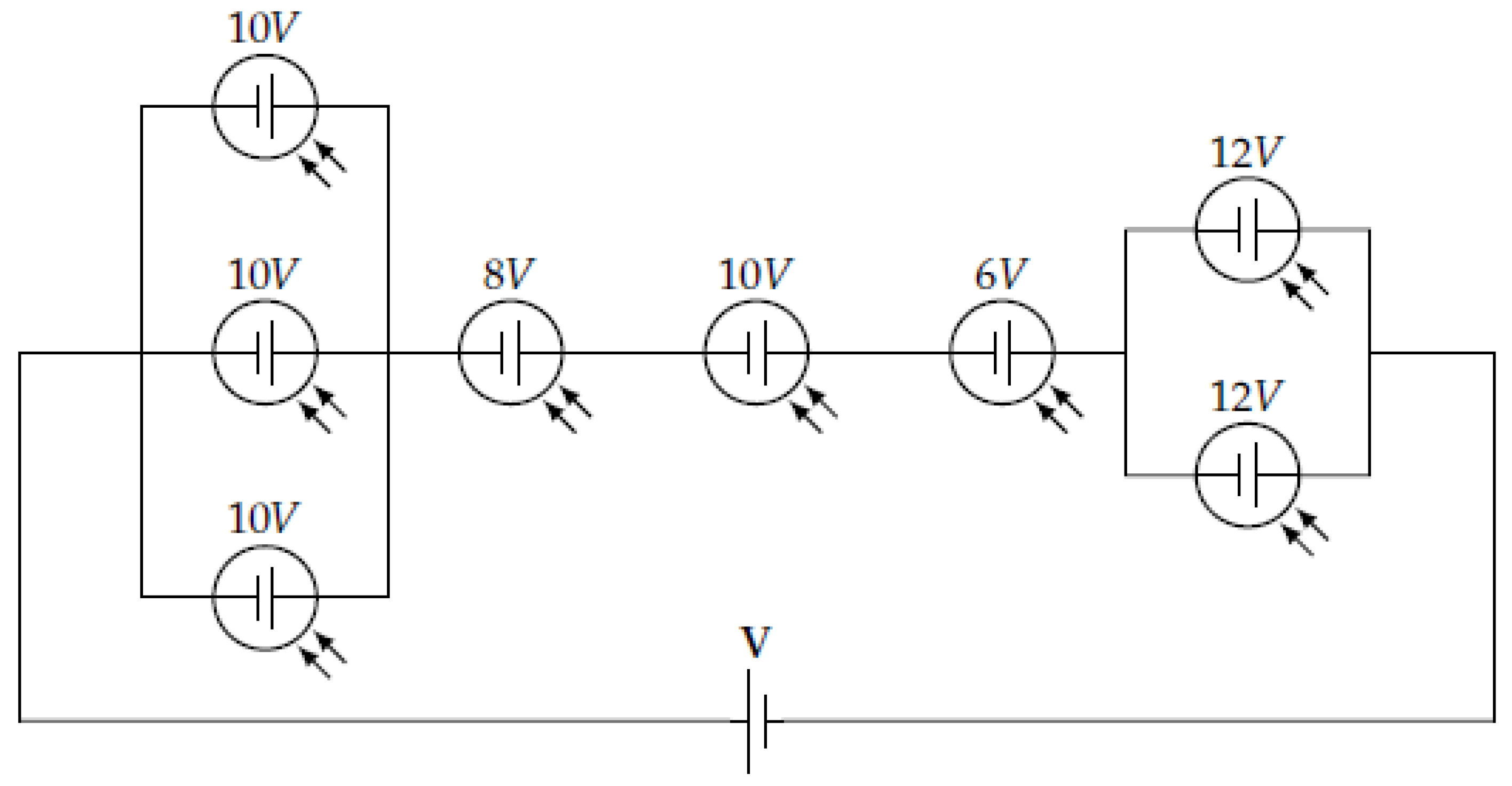
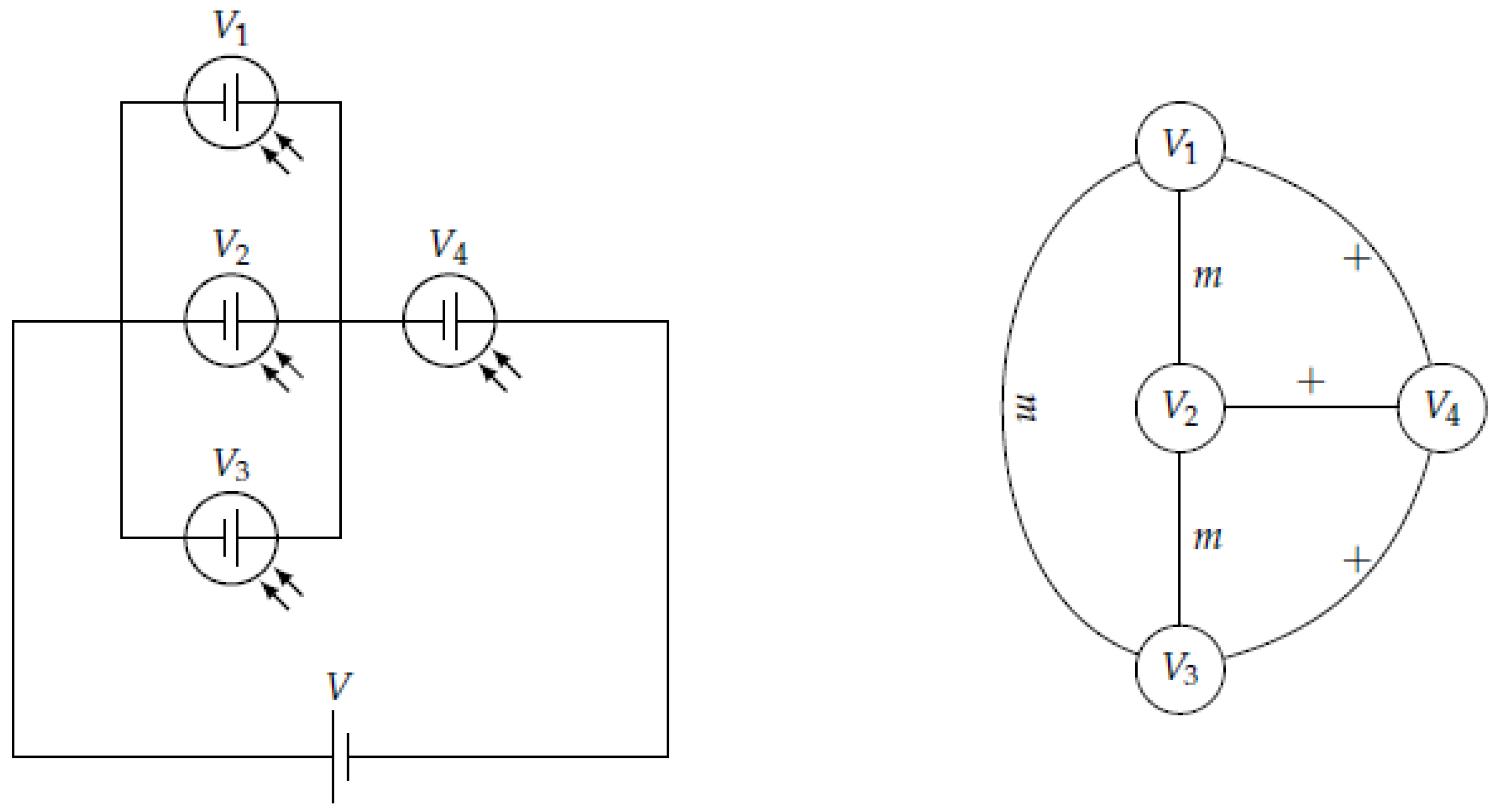
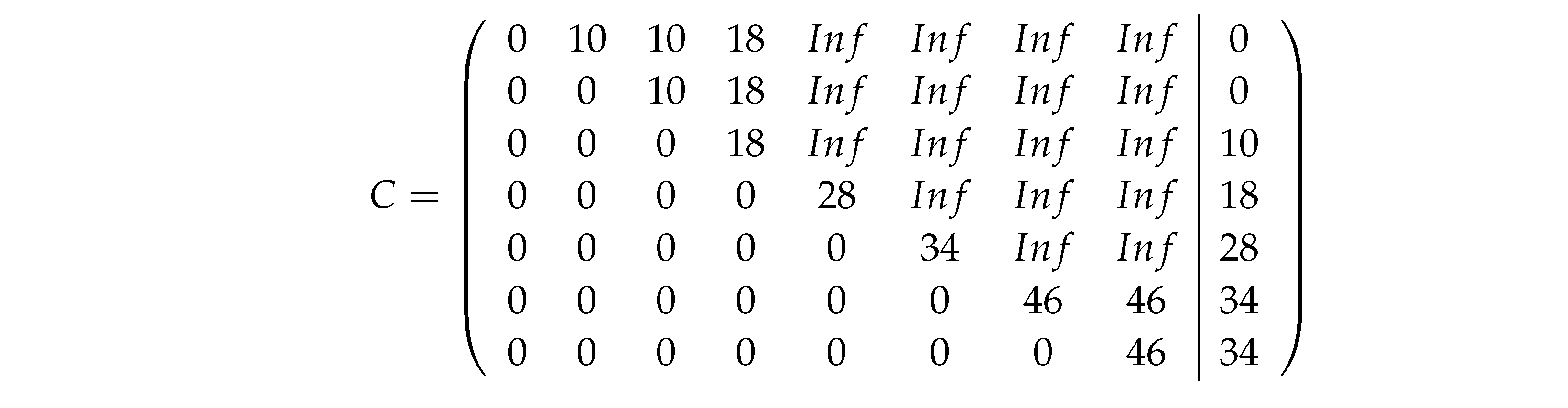
  • Matrix application of algorithm
    Sustainability 15 10858 i001
  • Computational resolution
The adjacency matrix is generated under the following assumptions:
  • −1 is a parallel connection (minimum);
  • 0 is a serial connection (sum);
  • 1 is no relation edge.
In the above case (Figure 10), it would be
A = 10 1 1 0 1 1 1 1 1 10 1 0 1 1 1 1 1 1 10 0 1 1 1 1 0 0 0 8 0 1 1 1 1 1 1 0 10 0 1 1 1 1 1 1 0 6 0 0 1 1 1 1 1 0 12 1 1 1 1 1 1 0 1 12
The algorithm in MATLAB (version R2020a) is executed in three phases:
1.
Sorting (in increasing order of types of connections exposed in the matrix A):
col=zeros(1,size(A,1));
for i=1:size(A,1)
    for j=i+1:size(A,1)-1
        for k=j+1:size(A,1)
            if A(i,j)>A(i,k) && col(j)==0
                pivot=A(j,:);A(j,:)=A(k,:); A(k,:)=pivot;
                pivot=A(:,j);A(:,j)=A(:,k); A(:,k)=pivot;
                col(j)=1;
                if j==size(A,1)-1
                    col(k)=1;
                end
            end
        end
    end
end
obtaining, in this case, the same matrix A as above.  
2.
Weights:
  A temporary weight matrix is created where
  • the weights are negative if it is a parallel join;
  • the weights are positive if it is a series connection;
B=[];
for i=1:size(A,1)
    for j=i+1:size(A,1)
        if A(i,j)==-1
            B(i,j)=-A(i,i);
        elseif A(i,j)==0
            B(i,j)=A(j,j);
        else
            B(i,j)=0;
        end
    end
end
obtaining
B = 0 10 10 8 0 0 0 0 0 0 10 8 0 0 0 0 0 0 0 8 0 0 0 0 0 0 0 0 10 0 0 0 0 0 0 0 0 6 0 0 0 0 0 0 0 0 12 12 0 0 0 0 0 0 0 12
3.
Electrical Dijkstra (with the accumulated increment at the last column):
increment=0;C=[]; C(1,size(A,1)+1)=0;
for i=1:size(A,1)
 
    if i>1 && B(i-1,i)>0
        increment=C(i-1,i)-A(i,i)
    end
 
    if i>1
        increment=max(increment,C(i-1,size(A,1)+1));
        C(i-1,size(A,1)+1)=increment;
    end
 
    for j=i+1:size(A,1)
        if B(i,j)<0
            C(i,j)=increment+min(-B(i,j),A(i,i));
        elseif B(i,j)>0
            C(i,j)=increment+A(i,i)+B(i,j);
        else
            if i>1
               if C(i-1,j)>0
                  C(i,j)=C(i-1,j);
               else
                  C(i,j)=inf;
               end
            else
               C(i,j)=inf;
            end
        end
    end
end
leaving
Sustainability 15 10858 i002

4. Dynamic Reconfiguration

Based on the reconfiguration of PVs, an algorithm was established to solve it by maintaining the voltage and maximizing the overall intensity. This improves the efficiency of the array through appropriate series or parallel connections of the panels. The system obtains the maximum energy intensity in DC until it reaches the inverter, which transforms it into AC and feeds it into the grid. This reconfiguration procedure is called Totally Cross Tied (TCT) and uses serial or parallel connections of each panel to its adjacent panels, using the switching matrix.

Maximum Efficiency Topology

The theoretical data acquisition device was proposed by F. Sánchez, M. Sidrach de Cardona et al. [9]. From this real-time measurement via PLC, it is possible to create topologies or reconfigurations with maximum efficiency. An important fact will be to reduce the downtime of the assembly, and hence the electronic devices and configurations that will be presented below.
The resolution algorithms will be based on the Minkowsky path theory and are developed using MATLAB. They allow the affected panels to be isolated or replaced without modifying the optimal output of the rest of the installation [13]. The final procedure was defined as the tree root algorithm.
Once the possible solutions (solution space) have been chosen, their measurement by means of the electric Dijkstra algorithm will give the objective function with which to achieve the optimal solution. This solution can be registered, by means of artificial intelligence, as the solution of a multilayer neural network. The inputs will be the different production states of the solar panels and the output will be the solution found, which will be implemented (Figure 11). This system will provide the permanent knowledge and learning to the system of choice of solutions.

5. Electronic Solutions

Once the theoretical model has been developed, a procedure should be established to arrive at the most effective technical solution. Therefore, the following models will be created:
1.
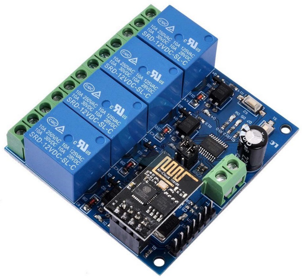
Low-cost model: development based on the Esp8266 chip with four relays. These devices will accompany each of the panels and will allow independent solutions, depending on their configuration, of maximum voltage and maximum amperage.
2.
Minimum model: simplification of the previous model based on the voltage drop on a relay. It offers constant voltage and is especially recommended for linear configurations (buses, trams, motorhomes, etc.).

5.1. Low-Cost Model

This model consists of two items. On the one hand, it makes use of the tree root algorithm, and on the other hand, it electronically develops the circuit diagram for real application [7].

5.1.1. Tree Root Algorithm

The algorithm on which this physical model has been built was explained in the article developed in 2018 by S. Merino, F. Sánchez, M. Sidrach de Cardona et al. [7]. It is based on the Minkowsky paths and, after its application (Figure 12), the following will be obtained:
δ = 1 1 1 1 1 1 1 1 1 1 1 1 1 1 1 1 1 1 1 1 1 1 1 1 D 0 = 1 1 1 1 1 1 2 1 2 2 2 2 1 0 1 3 3 3 0 0 0 4 4 4
D 1 = 1 1 1 1 1 1 2 1 2 2 2 2 1 0 1 3 3 3 0 0 5 4 4 4 D 2 = 1 1 1 1 1 1 2 1 2 2 2 2 1 0 1 3 3 3 0 6 5 4 4 4
D = 1 1 1 1 1 1 2 1 2 2 2 2 1 7 1 3 3 3 7 6 5 4 4 4

5.1.2. Electronic Development

The following low-cost devices (Figure 13) are used for their application:
The following are the new solutions (Figure 14 and Figure 15) that resolve the two possible situations: searching the maximum voltage or setting the maximum amperage.
Reconfiguration systems using quad relays managed by esp8266 devices (both figures).

5.2. Minimum Model

As mentioned above, one of the problems with the connection of the panels in photovoltaic parks today is that, in a first assembly, they are connected in parallel, in order to enable the maximum current contribution to the inverters. The main problem with this assembly lies in the fact that, when one of them reduces its performance due to shadows or dirt on its surface, the voltage of the set is reduced and, consequently, the energy supplied to the injector is minimized.
The solution found (Figure 16) proposes to use basic relays as a tool to establish a connection or to suppress it. Electrically, what is proposed is to use the energy generated in each of the sets of photovoltaic cells that make up the panel as a power supply to activate the switching of the panel’s own relay that will control the connection of the panel to the set of panels in parallel, adding its intensity to that generated by the other panels, or disconnecting that panel from the set (in the event of a decrease in the voltage or intensity generated).
As long as the array of cells allows, in its connection terminals, the potential difference that allows the parallel connection of the different arrays and their injection into the inverters, the relays will be activated and the current generated will be added, maintaining the voltage at the terminals of all the connections, individually, to the operating voltage of the inverters.
When, due to shadows or dirt on the cells, the voltage of the set does not reach the service voltage of the inverters, which is the same as the activation voltage of the relays, the relay in charge of managing the connection of that set will return to its idle state and that panel will be disconnected from the set. In this way, the operating voltage will be maintained, even if the current supplied by the panel is reduced, but the total power generated by the streamer will still be produced, even if a panel stops producing.
Once the problem has been rectified, the relay will automatically activate and reconnect the panel in parallel with the others.
This setup will allow the power generated by an array of PV panels to be optimized automatically and without the need for a microcontroller or management system.
The design would be optimized to the maximum if the panel could be fitted with multiple connections that would allow it to work with the minimum set of cells that make it up, and whose terminal voltage would be that of the injector’s service voltage. In this case, a relay would be placed in each of these connections, proceeding in the same way as described for the case of working with the whole panel, but improving the system by not eliminating the whole panel, but only the set in which some of the cells have been left in shadow.
The main novelties of this system are highlighted below:
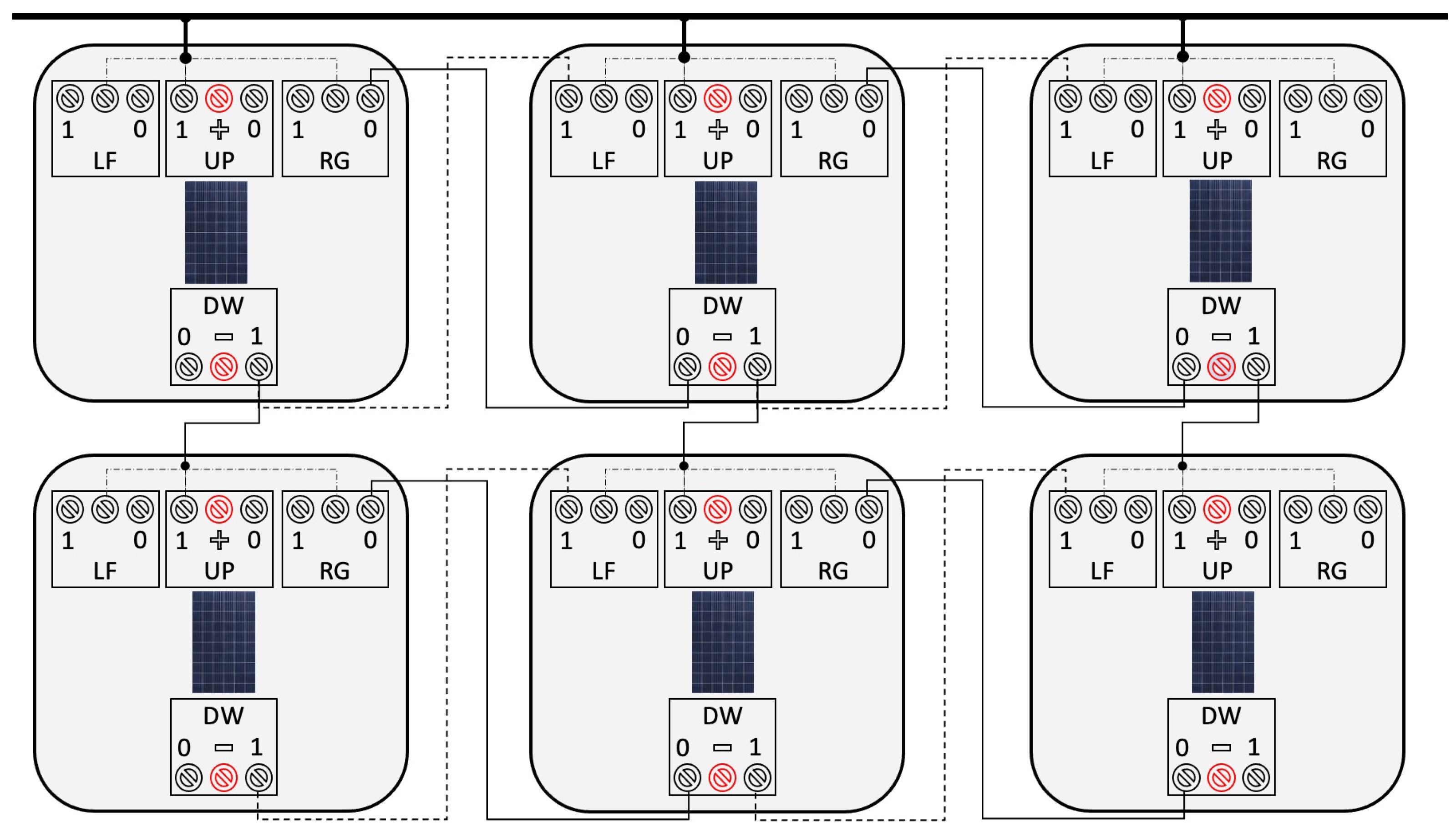
  • By working directly using the energy generated by the different panels as a source of energy for the activation of the switching relay, its operation is independent of any external system (either control or power supply) so that any environmental alteration or decrease in the supply of solar energy that affects the panel will lead to the switching of the relay.
  • The need for wiring is simplified to the maximum to control the switching and achieve the change of connection of the panels, going from series to parallel connection and vice versa when established by the conditions of energy production of the same at an individual level.
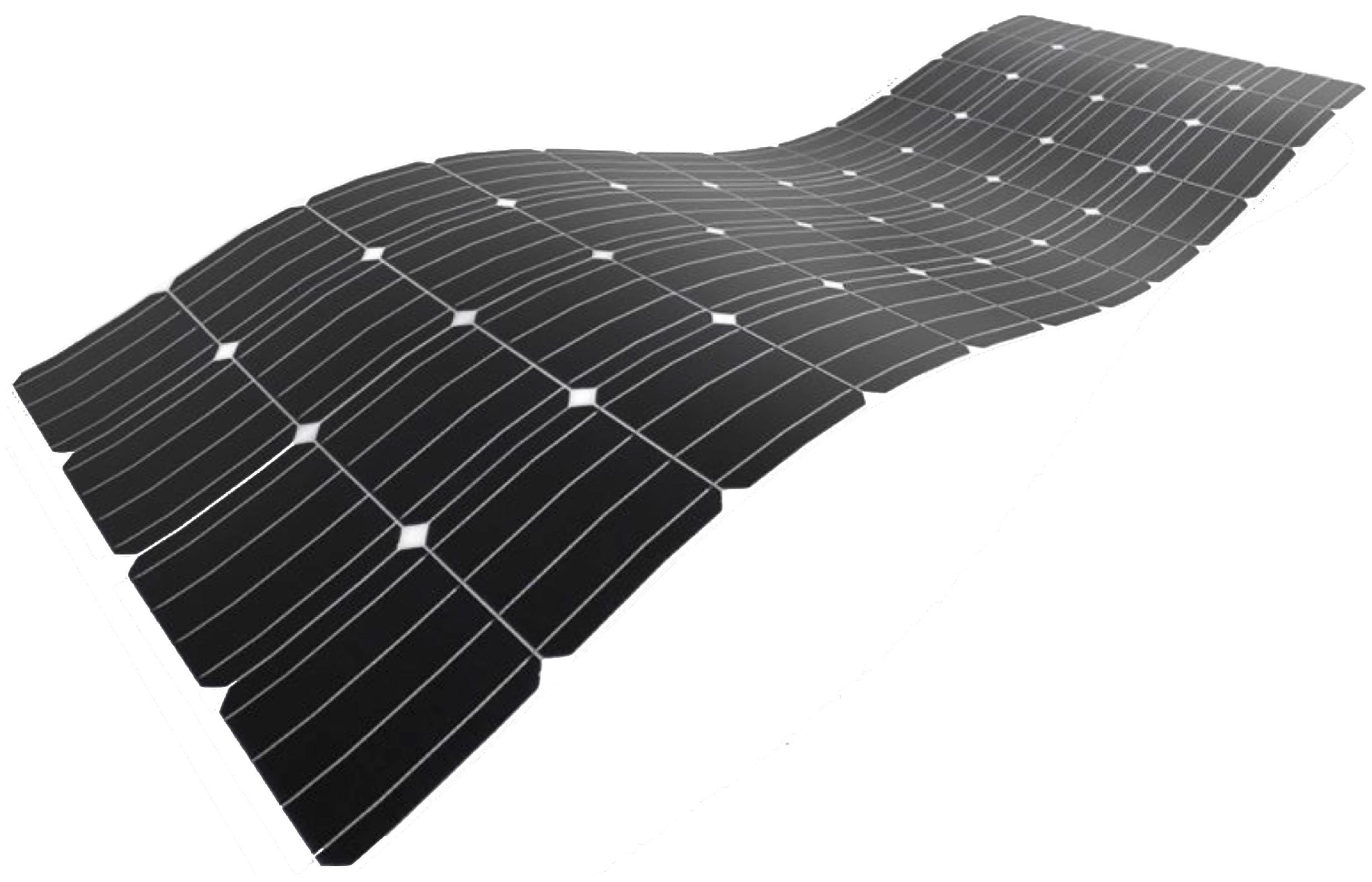
  • The system has been initially designed as a supplementary contribution to an energy supply system powered by batteries but, given that its application ensures the stability of the voltage supplied by the set of panels, it could be used as a primary energy system (provided that the number of panels installed supplies sufficient current to power the loads to be connected) and, if so desired, the surplus generated could be used to charge them during periods of inactivity (as in the case of flexible panels of Multijunction-MJ and Silicon-Si types studied by Masafumi Yamaguchi’s team [4]).
  • As it is a decentralised control system and autonomous operation, it does not require the intervention of microcontrollers and energy measurement systems that record the intensity supplied by each of the panels to establish the way in which it will be connected to the set.
The experiments carried out with the proposed system have shown that there is a significant unbalance between the voltage required to activate the relays and the value that causes them to deactivate. Moreover, this unbalance is particular to each relay model and even to each range within the model. For this reason, it has become essential to incorporate a pull-up and pull-down resistor [14] that minimizes the margin in which the value of the potential difference that conditions the series or parallel connection of the panel to the installation as a whole is considered appropriate.

6. Conclusions and Future Work

Having developed and tested the models for determining the optimum connection of the panels, related in this article, with the aim of ensuring the potential difference at the terminals of the power supply circuits and also the maximum current that the system can supply under these conditions, the following aspects have been explored:
  • Complexity: From the point of view of computational complexity, for the application of control algorithms based on software logic, using a microcontroller with its appropriate programming to send orders to the sp8266, this, in turn, organizes the serial or parallel connection of the adjacent panels, and it is more appropriate to program it on the so-called “low-cost” model using MATLAB [15].
  • Non-linear distribution: In panels with non-linear or non-geometric distribution (for example, in solar farms), management must be carried out by means of low-cost models using linear programming techniques. For this purpose, an objective function (Adjacency Matrix) will be established and the possible solutions will be evaluated through the electric Dijkstra algorithm presented in this work.
  • Minimum model: Considering the simplicity of the installation, for systems that interact automatically by potential drop, the minimum model optimizes the cost of the total installation and the number of devices and, therefore, reduces the complexity of the system. The relays responsible for establishing the electrical connection mode will be located on the panels themselves.
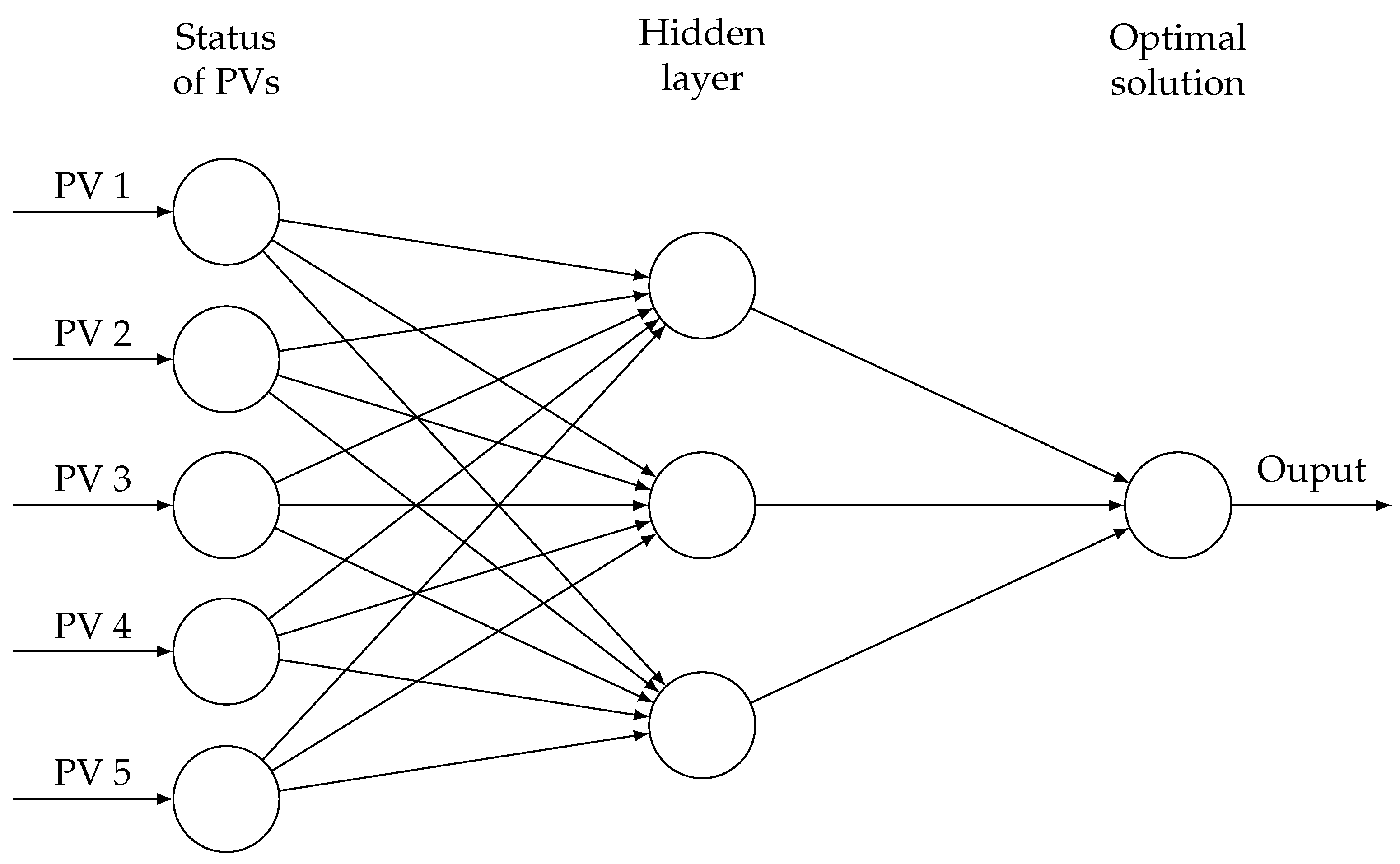
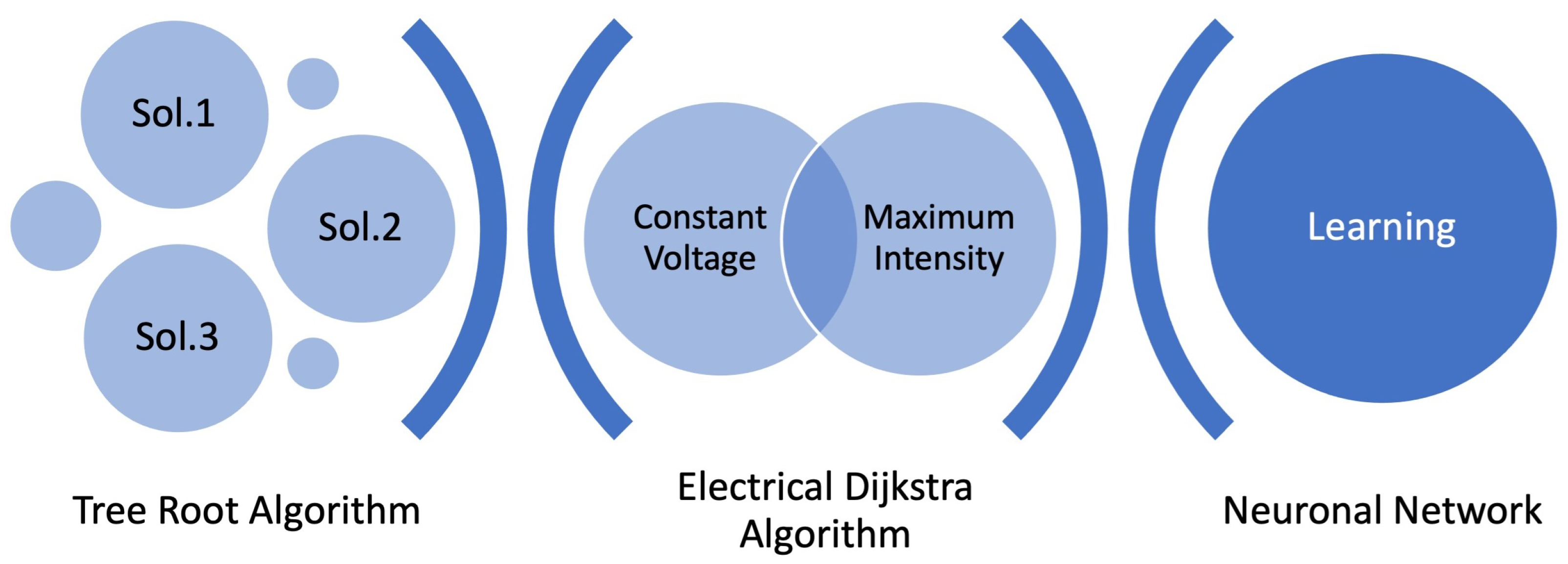
  • Artificial intelligence: As an application of artificial intelligence, when establishing the mechanism for solving this problem, the result is optimized by searching the solution space using the tree root algorithm. Finally, after finding the most efficient solution, the underlying neural network will be reprogrammed, providing new knowledge and learning to the system (Figure 17).
In the future, both models will be applied depending on the expected panel distribution [16]. Two cases are foreseen:
1.
Non-linear distribution (Figure 18): Applied to boats and cars.
Given the complexity of their possible PV surfaces, flexible panels would be used and solved by the low-cost model.
2.
Linear distribution (Figure 19): Applied to buses and trams.
Due to their rectangular and elongated roofs, they offer a suitable layout for linear configurations, being solvable under the minimum model.
Working with large-volume means of transport that are exposed to the open air makes it possible to incorporate a high energy storage capacity. In these cases, the combination of optimized charging while moving or stationary increases the stored energy [17] and therefore the autonomy of these means of transport. Therefore, future work will focus on the applicability of the techniques and devices presented here, on the one hand, and on battery designs based on different materials [5] and with higher charging capacity [18], on the other.

Author Contributions

Methodology, F.S.; Formal analysis, S.M., J.M., F.G., J.d.D.L., J.R.H. and M.S.d.C.; Investigation, J.d.D.L., R.G., F.S., J.R.H. and M.S.d.C.; Data curation, R.G.; Writing—original draft, S.M. and F.G.; Writing—review & editing, J.M. All authors have read and agreed to the published version of the manuscript.

Funding

This paper is supported from University of Malaga and CBUA (funding for open access 373 charge: Universidad de Málaga/CBUA).

Data Availability Statement

Not applicable.

Acknowledgments

We thank the University of Malaga and CBUA for the support of this paper, and we thank also the anonymous reviewers whose suggestions helped improve and clarify this manuscript.

Conflicts of Interest

The authors declare no conflict of interest.

References

  1. Muttana, S.; Dey, R.; Sardar, A. Prospects of Electric Bus Integrated with Solar Photovoltaic Cells; SAE Technical Paper; SAE: Warrendale, PA, USA, 2017. [Google Scholar] [CrossRef]
  2. Myeongchan, O.; Sung-Min, K.; Hyeong-Dong, P. Estimation of photovoltaic potential of solar bus in an urban area: Case study in Gwanak, Seoul, Korea. Renew. Energy 2020, 160, 1335–1348. [Google Scholar]
  3. Nassiri Nazif, K.; Daus, A.; Hong, J.; Lee, N.; Vaziri, S.; Kumar, A.; Nitta, F.; Chen, M.E.; Kananian, S.; Islam, R.; et al. High-specific-power flexible transition metal dichalcogenide solar cells. Nat. Commun. 2021, 12, 7034. [Google Scholar] [CrossRef] [PubMed]
  4. Yamaguchi, M.; Masuda, T.; Araki, K.; Sato, D.; Lee, K.H.; Kojima, N.; Takamoto, T.; Okumura, K.; Satou, A.; Yamada, K.; et al. Development of high-efficiency and low-cost solar cells for PV-powered vehicles application. Prog. Photovoltaics Res. Appl. 2021, 29, 684–693. [Google Scholar] [CrossRef]
  5. Wartak, M.S.; Tsakmakidis, K.L.; Hess, O. Introduction to metamaterials. Phys. Can. 2011, 67, 30–34. [Google Scholar]
  6. Merino, S.; Guzmán, F.; Martínez, J. Metadomotic optimization using genetic algorithms. Appl. Math. Comput. 2015, 267, 170–178. [Google Scholar] [CrossRef]
  7. Merino, S.; Sánchez, F.J.; Sidrach-de-Cardona, M.; Guzmán, F.; Guzmán, R.; Martínez, J.; Sotorrío, P.J. Optimization of energy distribution in solar panel array configurations by graphs and Minkowski’s paths. Appl. Math. Comput. 2018, 319, 48–58. [Google Scholar] [CrossRef]
  8. Petrone, G.; Spagnuolo, G.; Zhao, Y.; Lehman, B.; Ramos-Paja, C.A.; Orozco, M.L. Control of Photovoltaic Arrays, Dynamical Reconfiguration for Fighting Mismatched Conditions and Meeting Load Requests. IEEE Ind. Electron. Mag. 2015, 9, 62–76. [Google Scholar]
  9. Sánchez, F.J.; Sotorrío, P.J.; Heredia, J.R.; Pérez, F.; Sidrach-de-Cardona, M. PLC-Based PV Plants Smart Monitoring System: Field Measurements and Uncertainty Estimation. IEEE Trans. Instrum. Meas. 2014, 63, 2215–2222. [Google Scholar] [CrossRef]
  10. Dallago, E.; Liberale, A.; Miotti, D.; Venchi, G. Direct MPPT algorithm for PV sources with only voltage measurements. IEEE Trans. Power Electron. 2015, 30, 6742–6750. [Google Scholar] [CrossRef]
  11. Ustun, T.S.; Ozansoy, C.; Zayegh, A. Implementation of Dijkstra’s algorithm in a dynamic microgrid for relay hierarchy detection. In Proceedings of the 2011 IEEE International Conference on Smart Grid Communications (SmartGridComm 2011), Brussels, Belgium, 17–20 October 2011. [Google Scholar] [CrossRef]
  12. Mohan, P. Determining the Shortest Current Flow Path Using Dijkstra’s Algorithm in Mess Circuit. Int. J. Innov. Technol. Explor. Eng. 2019, 8, 1635–1638. [Google Scholar]
  13. Amaresh, K.; Sankar, V. Modeling of Photovoltaic System Interconnected with Radial Distribution System using MATLAB/SIMULINK. Int. J. Eng. Innov. Technol. 2013, 3, 251–257. [Google Scholar]
  14. Glaser, C. Solar Panel MPPT for Pulsed-load Applications. In Solar Technology; Texas Instruments: Dallas, TX, USA, 2022. [Google Scholar]
  15. Grama, A.; Dan, M.; Lázár, E. Photovoltaic panel model using Matlab. In Proceedings of the 39th International Spring Seminar on Electronics Technology (ISSE), Pilsen, Czech Republic, 18–22 May 2016; pp. 322–327. [Google Scholar] [CrossRef]
  16. Möller, M.C.; Krauter, S. Hybrid Energy System Model in Matlab/Simulink Based on Solar Energy, Lithium-Ion Battery and Hydrogen. Energies 2022, 15, 2201. [Google Scholar] [CrossRef]
  17. Yan, H.W.; Narang, A.; Tafti, H.D.; Farivar, G.G.; Ceballos, S.; Pou, J. Minimizing Energy Storage Utilization in a Stand-Alone DC Microgrid Using Photovoltaic Flexible Power Control. IEEE Trans. Smart Grid 2021, 12, 3755–3764. [Google Scholar] [CrossRef]
  18. Chacón, J.; Soler, P.R. Electrically rechargeable Aluminum-air batteries to power Smart Cities. In Proceedings of the 2013 International Conference on New Concepts in Smart Cities: Fostering Public and Private Alliances (SmartMILE), Gijon, Spain, 11–13 December 2013; pp. 1–4. [Google Scholar] [CrossRef]
Figure 1. Flexible PV (source: ASQ Australian Solar Quotes).
Sustainability 15 10858 g001
Figure 2. Solar tram carriages (source: self-design).
Sustainability 15 10858 g002
Figure 3. Matrix configuration.
Sustainability 15 10858 g003
Figure 4. Parallel connection matrix of strings made of PVs connected in series.
Sustainability 15 10858 g004
Figure 5. PV panel I–V characteristic curves under applied climatic conditions: PVP 1 (dotted line), PVP 2 (small dashed line), PVP 3 (big dashed line), and String (solid line).
Sustainability 15 10858 g005
Figure 6. Series and parallel voltage and intensity.
Sustainability 15 10858 g006
Figure 7. First example of transition from electrical circuit to mathematical graph.
Sustainability 15 10858 g007
Figure 8. Second example of transition from electrical circuit to mathematical graph.
Sustainability 15 10858 g008
Figure 11. Multilayer neural network on PV states.
Sustainability 15 10858 g011
Figure 12. Example to solve (non-linear distribution).
Sustainability 15 10858 g012
Figure 13. Control device via esp8266 for 4 relays (quad relay system).
Sustainability 15 10858 g013
Figure 14. Maximum voltage (parallel connection).
Sustainability 15 10858 g014
Figure 15. Maximum amperage (serial connection).
Sustainability 15 10858 g015
Figure 16. Minimal model in linear distribution (two columns of panels).
Sustainability 15 10858 g016
Figure 17. Artificial intelligence process.
Sustainability 15 10858 g017
Figure 18. Non-linear distribution.
Sustainability 15 10858 g018
Figure 19. Linear distribution.
Sustainability 15 10858 g019
Disclaimer/Publisher’s Note: The statements, opinions and data contained in all publications are solely those of the individual author(s) and contributor(s) and not of MDPI and/or the editor(s). MDPI and/or the editor(s) disclaim responsibility for any injury to people or property resulting from any ideas, methods, instructions or products referred to in the content.

