Article

Effect of Embedded Depth of Copper-Nickel-Plated Sensor Probes on Compressive Strength Development of Mortar

1
Department of Regional Infrastructure Engineering, Kangwon National University, Chuncheon 24341, Republic of Korea
2
Department of Civil and Environmental Engineering, University of Alabama in Huntsville, Huntsville, AL 35899, USA
3
Department of Construction Science, Texas A&M University, College Station, TX 77843, USA
*
Author to whom correspondence should be addressed.
Sustainability 2023, 15(14), 10772; https://doi.org/10.3390/su151410772
Submission received: 13 June 2023 / Revised: 6 July 2023 / Accepted: 7 July 2023 / Published: 9 July 2023

Abstract

:
Embedded sensors are widely employed for the structural health monitoring of structures constructed with concrete or mortar. Despite embedded sensors being actively used, there has been no study on whether or not the sensor probe placement within structures made of concrete or mortar influences their structural stability. The strength of small structures in particular could be affected by sensor probes embedded within them. To address the lack of research in this area, this study analyzed the effect of embedding positions of sensor probes on the compressive strength development of mortar. After the production of mortar specimens with the depth of the embedded sensor being controlled by the developed mold, compressive strength tests were conducted, and then test results were verified through finite element analysis. For testing, copper–nickel-plated sensor probes were embedded within the mortar because these sensor probes are popular commercial probes. The test results show that the compressive strength was 7.1 MPa when the sensor probe was embedded at a depth of 5 mm. In contrast, the compressive strength was 28.2 MPa at a depth of 30 mm. Since the compressive strength without the embedded sensor probe was 29.8 MPa, considering the results of this study, it is highly recommended that copper–nickel-plated sensor probes be embedded at least 30 mm from the surface of mortar structures.

1. Introduction

The Internet of Things (IoT) is a technology allowing physical objects that cannot communicate to connect and exchange measured information with other systems via a wireless network. It is an innovative technology in the information technology (IT) field that connects physical objects through the Internet [1]. Among the many IoT technologies currently available, wireless sensor networks (WSNs) are the most important technology because WSN nodes enable data measured by sensors to be sent and received without wires [2]. These networks can send data when physical or environmental changes are measured from different locations, such as temperature, sound, vibration, pressure, motion, pollutants, etc. [3,4]. Sensors are being rapidly applied across many industrial fields, including the agricultural, medical [5,6], civil engineering [7], and architectural fields [8]. In particular, various sensors are employed to measure the changes in concrete or mortar, including temperature, humidity, corrosion, level of pH, and pressure [9], because cementitious materials, such as concrete and mortar, are frequently employed in the construction engineering field [10].
Over time, structures constructed with cementitious materials can be damaged due to chemical and environmental factors, such as alkali–silica reactions, freeze–thaw cycles, etc. [11]. An alkali–silica reaction can cause deterioration by inducing expansion and cracking from within [12]. Also, repeated freezing and thawing due to sudden temperature changes can result in scaling and micro-cracks on the surface of concrete or mortar [13]. Consequently, the health monitoring of structures constructed with cementitious materials is required for their stability and durability [14]. Sensors widely employed for monitoring cementitious materials can be broken down into two categories: contact and non-contact types [9]. A piezoelectric sensor is a representative contact-type sensor that is attached to the surfaces of concrete or mortar structures which assesses their statuses by measuring the electrical signal corresponding to the physical deformation rate [15]. Although contact-type sensors have high accuracy and a low cost, stable and constant measurement can be affected by environmental influences because they are attached to the structure surface [16]. Non-contact-type sensors, such as those using optical fibers and electromagnetic waves, have the advantage of easy data measurement [17]. Still, accuracy is lower when they are applied to cementitious structures [18]. To address the drawbacks of both contact and non-contact methods, embedded sensors buried within concrete or mortar structures are being developed extensively [19]. These embedded sensors have enhanced durability and accuracy because they are not directly affected by the surrounding environment [20]. As a result, the construction industry is actively researching the use of embedded sensors to monitor internal changes in cementitious structures, particularly in mortar. However, sensors embedded into the mortar may affect the overall structural properties of the material. Therefore, in this study, the effects of these embedded sensors may have on mortar were analyzed.

2. Literature Review

There have been several studies examining different methods of using embedded sensors to monitor mortar. Ekaputri et al. [21] proposed a method of using embedded sensors to monitor the relative humidity inside the mortar. In their study, ordinary mortar specimens made with ordinary Portland cement were compared with blast furnace slag (BFS) mortar specimens made by replacing 40% of the cement with BFS. Probes of humidity sensors were inserted into each specimen for monitoring, and the results show that the BFS mortar specimens had a lower internal relative humidity than ordinary mortar specimens due to their physical and chemical properties. Zhou et al. [22] suggested embedding cement-based piezoelectric ceramic sensors in mortar to monitor the propagation of cracks in real time. In their study, they fabricated cement-based piezoelectric ceramic composite materials and sensors, connected them to an acoustic emission (AE) monitoring system, and presented a real-time method for detecting AE signals during cubic split tests on mortar. To do this, eight AE sensors were embedded in the corners of 300 × 300 × 300 mm mortar specimens, and cubic split tests were performed. As a result, they proved that cement-based piezoelectric ceramic sensors could be used to monitor crack propagation in real time. Im et al. [23] developed an ultra-thin iron corrosion sensor covered with an anion exchange membrane to monitor the corrosion level of rebars within reinforced concrete effectively. In their study, they embedded the developed sensor at 10 mm intervals in mortar specimens. They measured the chloride concentration in the mortar through the sensor’s resistance value as chloride ions penetrated the mortar. The results show that the developed sensor was sensitive to the penetration of chloride ions. Still, the authors mentioned that for application in real construction sites, the sensor must be able to withstand greater stress, as concrete has a higher strength than mortar. Pan and Huang [24] applied piezoelectric cement sensors based on the electromechanical impedance (EMI) technique to monitor the strength of mortar. In their study, they embedded piezoelectric cement (PCE) and lead zirconate titanate (PZT) sensors in three types of mortar specimens with W/C ratios of 0.4, 0.5, and 0.6 and monitored their compressive strength for 56 days. The results show that the strength monitoring performance of PEC sensors was similar to that of PZT sensors. However, the monitoring performance of PEC sensors was considered superior because their electrical impedance changes were more apparent than those of the PZT sensors. Accordingly, the authors mentioned that PEC sensors are particularly suitable for monitoring changes in the material properties of cement-based materials. Sampaio et al. [25] developed an iridium oxide (IrOx)-based sensor sensitive to pH to present a method for manufacturing and characterizing embedded sensors for monitoring the pH concentration of steel embedded in mortar. In their study, they embedded the developed sensor in mortar specimens for verification and conducted monitoring after exposing them to a sulfuric acid solution. The results demonstrate that the developed sensor successfully measured the pH changes inside the mortar in real time and stably operated even when exposed to a sulfuric acid solution. The objectives and novelties of this literature are summarized in Table 1.

3. Problem Statement and Research Objective

The literature review indicates that embedded sensors are widely utilized in the construction industry to detect and measure changes within mortar. Employing embedded sensors offers a promising non-destructive approach to collecting vast amounts of data [9] and can be used to accurately identify internal changes [26]. However, embedding sensors in cement-based materials such as concrete or mortar may require sensor probes to protect themselves from chemical reactions characterized by high alkalinity and hydration heat in the mortar [27]. These embedded sensor probes comprise various materials, including stainless steel and carbon fibers [28,29]. This means that mortar strength may not reach the planned levels due to the different physical properties of these materials. However, existing research has primarily focused on the feasibility of measuring internal changes with embedded sensor probes. The impact of probe location and presence on material strength has yet to be investigated. Consequently, this study aimed to experimentally examine the influence of embedded sensor probes on the compressive strength of mortar, validate the experimental findings through numerical analysis, and suggest appropriate probe placement to ensure the achievement of the desired compressive strength. Ultimately, this study provides crucial data to ensure sustainable structural stability when sensors inserted into their probes are embedded in mortar structures.

4. Research Methodology

For structural members such as reinforced rebars embedded in mortar, the thickness of the mortar starting from the top section of the embedded structural member to the surface of the cementitious structure is crucial. If the mortar covering is not thick enough, it cannot last over the expected lifetime of a cementitious structure due to cracking along the embedded structural member, neutralization, and corrosion of the member [30].
Therefore, in this study, to examine mortar strength development when the covering thickness from the top section of the embedded structural member to the surface of the cementitious structure is changed, the embedding position of the sensor probe in the mortar was set as a variable, and a compressive strength test was conducted on the mortar specimens with the probe embedded at each position. Additionally, the compressive strength test results were verified through finite element analysis.

5. Experiment Materials and Methods

5.1. Materials and Mix Design

The cement employed for producing mortar in this study was ordinary Portland cement. Ordinary Portland cement usually consists of silicon dioxide (SiO2), iron oxide (Fe2O3), calcium oxide (CaO), aluminum oxide (Al2O3), along with trace elements like magnesium oxide (MgO) and sulfur trioxide (SO3) [31]. These ingredients determine the performance of the cement, such as initial setting time, strength development, heat of hydration, and corrosion resistance [32]. The ingredients of the employed ordinary Portland cement were the same as the specifications provided by ASTM C150 [33], as shown in Table 2. According to ASTM C 928 [34], the 28-day compressive strength of repair concrete and mortar should be at least 28 MPa. Therefore, in this study, the design reference strength of the mortar was planned to be at least 28 MPa when there is no embedded sensor within the mortar. For the mortar compressive strength test, the proportions of the mortar mix were 1:2.75:0.485 (cement/sand/water) according to ASTM C109 [35]. To ensure that the materials were uniformly mixed, the water and cement were added to the mixer at a speed of 140 ± 5 r/min for 30 s following ASTM C305 [36], followed by the addition of all the sand, and mixed for another 30 s at a speed of 285 ± 10 r/min. The machine was then stopped for 90 s to enable us to scrape the mortar off the sides and mixing was commenced for 60 s at 285 ± 10 r/min.

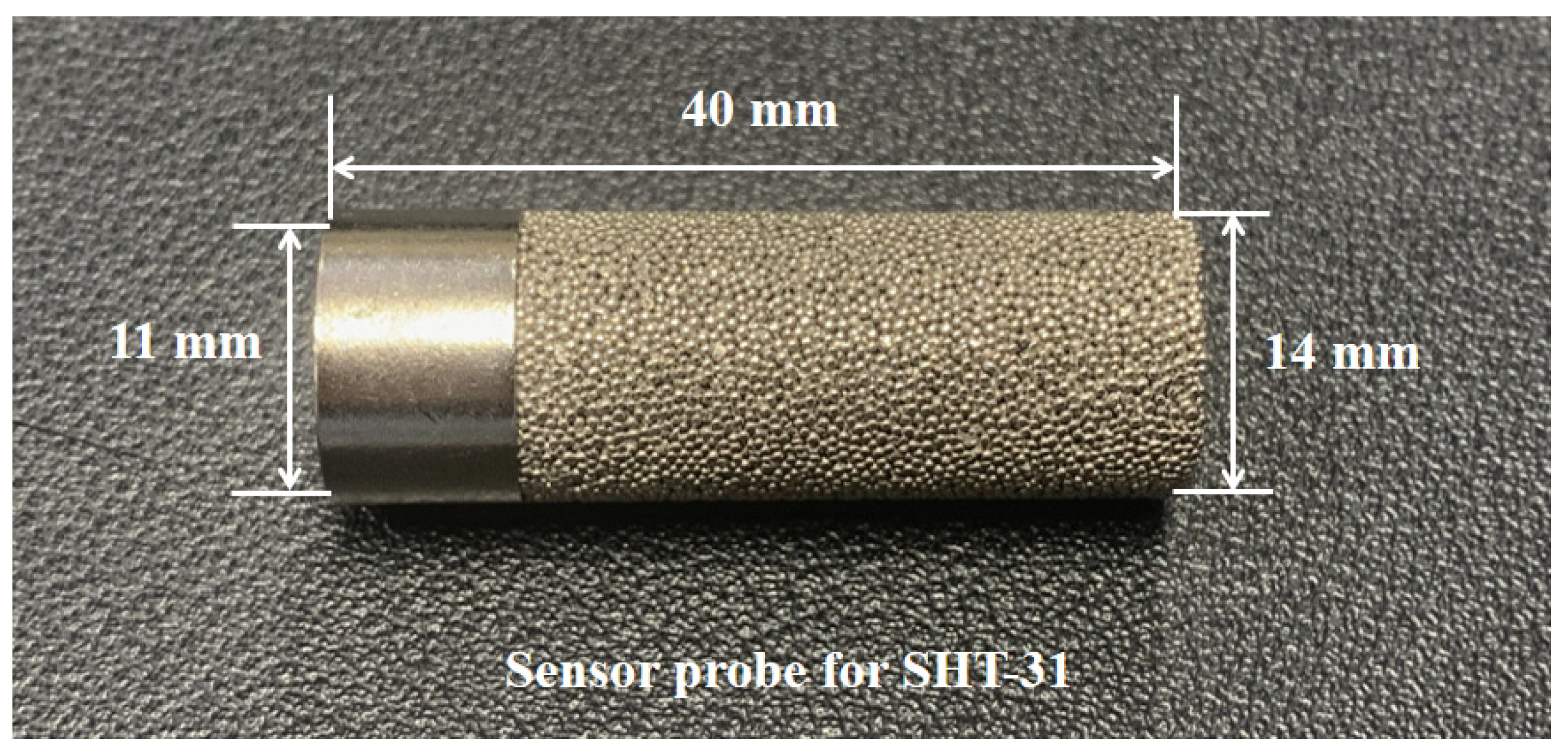
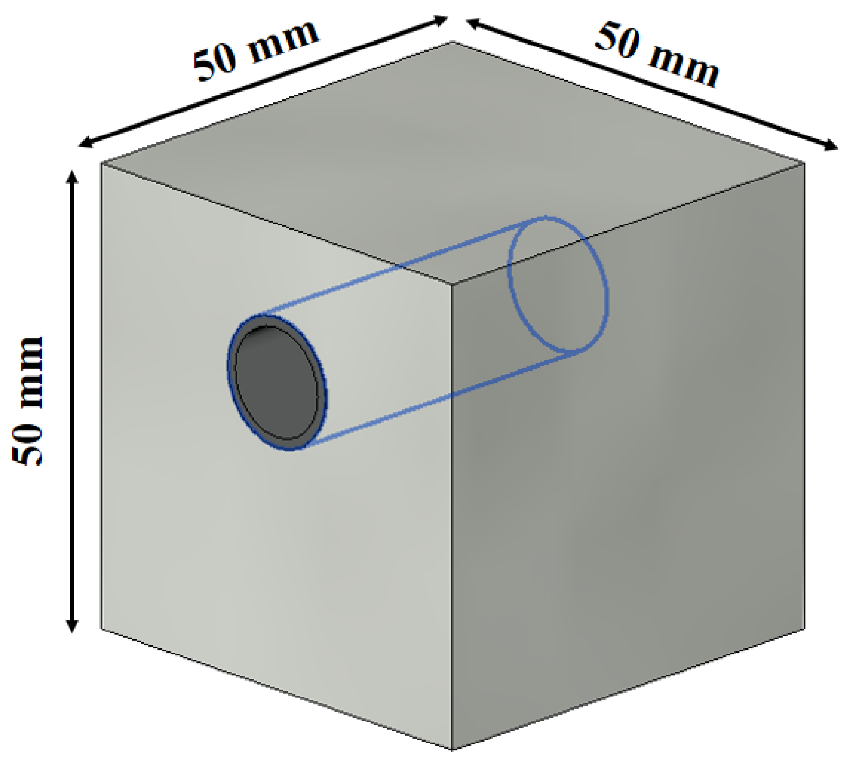
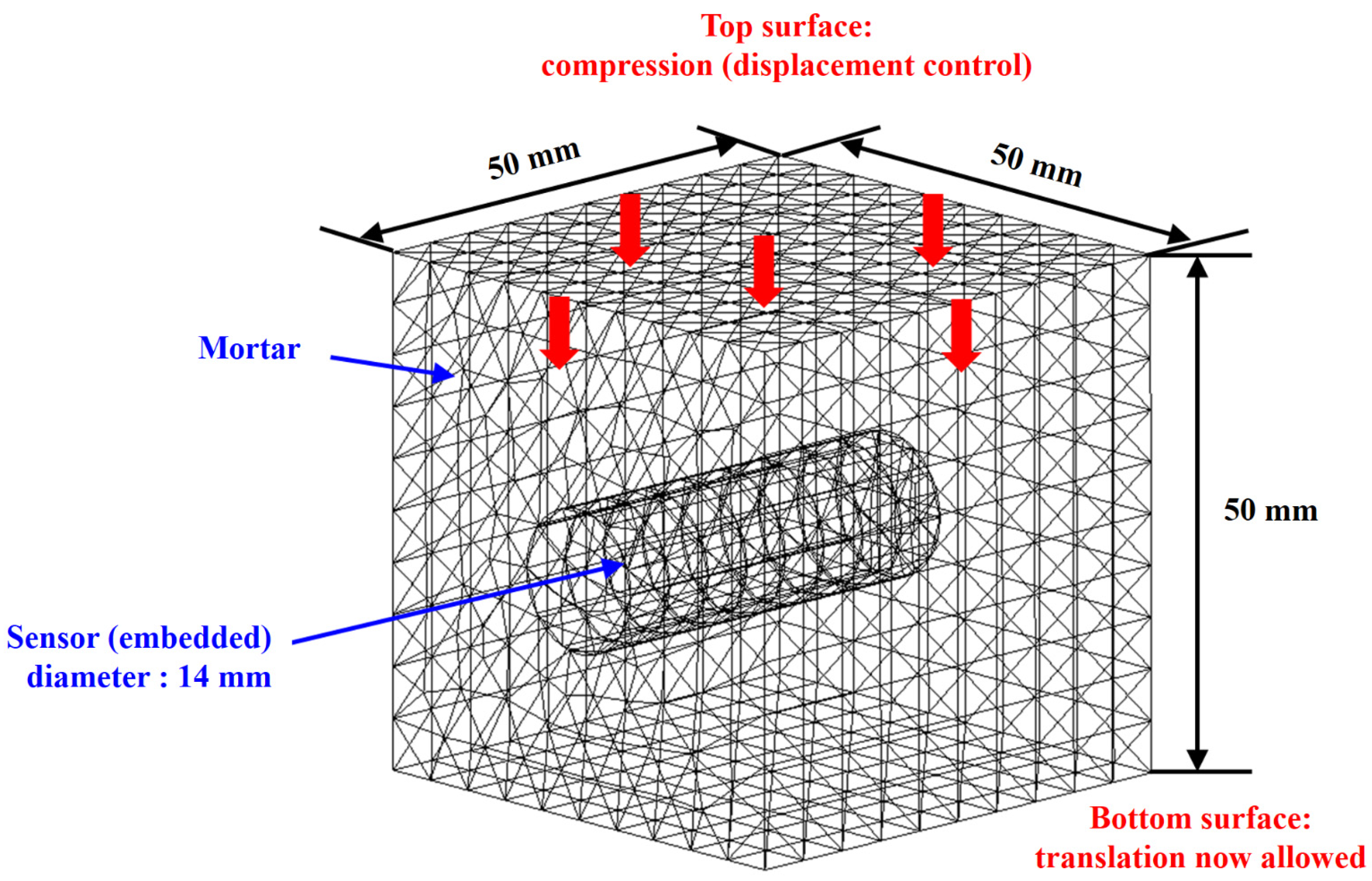
5.2. Sensor and Specimen Size Setting

In this study, the effect of changing the embedding position of the sensor probe on the compressive strength, with respect to mortar cover thickness, was investigated through experiments to determine the sensor probe position that satisfies the compressive strength requirements. The sensor used was the SHT-31, a temperature and humidity sensor made by Sensirion [37]. The probe of this sensor has a total length of 40 mm, an outer diameter of 14 mm, and an inner diameter of 11 mm, as shown in Figure 1. It is made of nickel-plated copper to allow it to withstand corrosion and the heat of hydration in the alkaline environment inside mortar [38]. The mortar specimen for embedding the sensor probe was prepared in the form of a cube 50 mm in width, length, and height, as shown in Figure 2. The embedment position of the sensor probe was set by adjusting the sheath thickness at 5 mm equidistant intervals, which provided control of the experimental variables, and the probe was embedded at distances ranging from 5 mm to 30 mm from the surface.

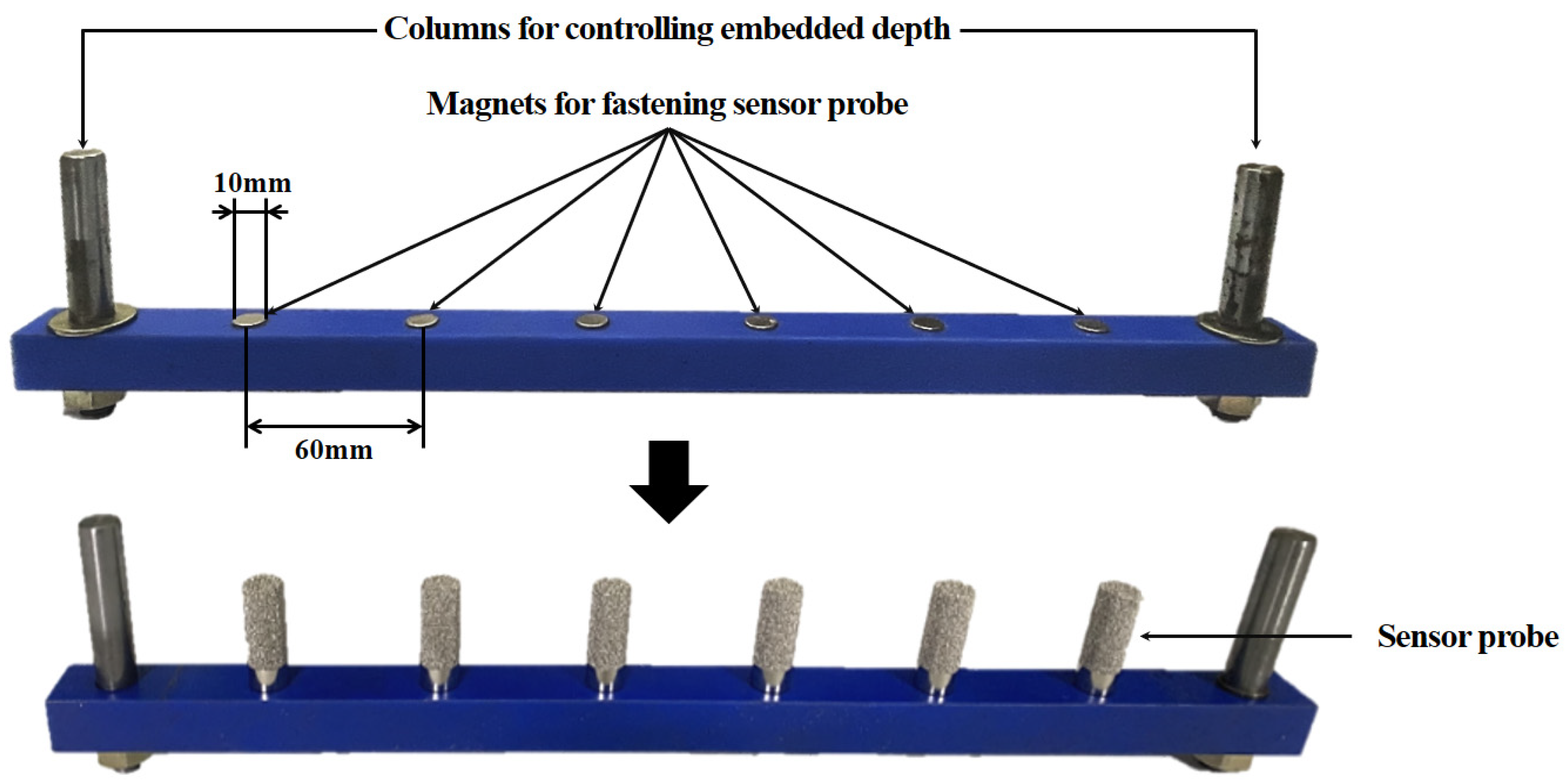
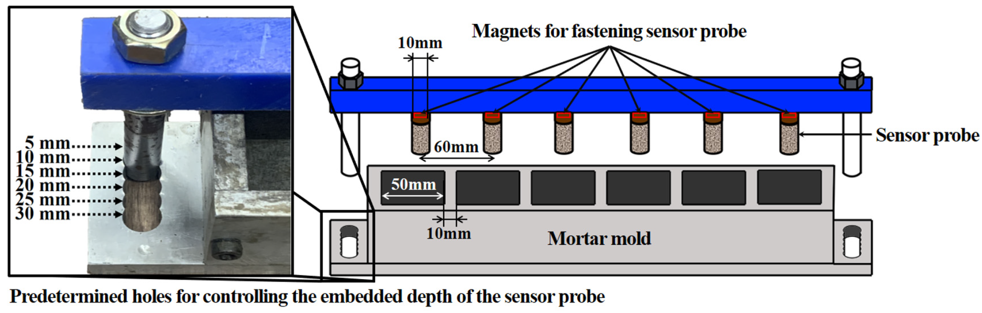
5.3. Production of Test Specimens

To produce specimens for determining the compressive strength development according to the embedment setting of a sensor probe, the probe should be embedded along with the mortar pour and then cured. However, suppose the sensor probe is embedded immediately after pouring; the setting of the sensor probe in the mortar may change while curing due to its self-weight, resulting in it sinking into the mortar or tilting. Therefore, a mold was created that allows the control of the probe embedment setting to be varied, ensuring that the probe remains at the planned embedment depth during curing in the mortar without moving and producing specimens with evenly spaced cover thicknesses. The sensor probe material employed in this study was copper plated with nickel. Although copper is a non-magnetic material [39], this sensor has been proven to be a ferromagnetic material because nickel is plated on the surface of copper. Therefore, it magnetizes the copper so that it sticks to magnets [40]. Based on these material properties, a rod was fabricated to control the depth at which the probe was set, allowing the probe to be embedded into the mortar after probes covered with magnets were placed on the depth control bar at each embedding position set as an experimental variable, as shown in Figure 3. Magnets with a diameter of 10 mm, which is smaller than the inner diameter of the probe (11 mm), were installed at 60 mm intervals on the depth control rods to ensure that the rods and the probes were entirely attached, preventing the probe from moving inside the mortar while curing. Additionally, a method of setting the probe position was employed by pouring mortar into a cube mold, as shown in Figure 4, allowing the rods to be secured at 5 mm intervals and ensuring accurate mounting at the set embedment position. The mold used for this study is shown in Figure 5.
After 24 h of curing, the rods used for setting the probe locations were removed from the surface of the mortar. The probes were only left in the cured mortar because they were stuck in the probe setting bar due to the magnets, as shown in Figure 6. The specimens prepared in this manner were subjected to wet curing for 28 days in a water bath at a temperature of 23 °C ± 2 °C, as specified in ASTM C511 [41], and were then tested for compressive strength. HCT-DH 200 [42], a digital compressive material-testing machine from Heungjin with a capacity of up to 2 MN, was used for the tests.

6. Finite Element Analysis

A finite element (FE) analysis, as described in this section, was used to numerically investigate the structural stability of mortar specimens equipped with an embedded sensor probe according to its embedded depth. The commercial finite element software ABAQUS 2022 was used in this work, as it can provide robust, accurate, and high-performance solutions for nonlinear problems. The damaged plasticity model in ABAQUS, which is based on Lubliner, Oliver et al. [43] and modified by Lee and Fenves [44], is a suitable material library with which to model the plastic-damage behavior of quasi-brittle materials such as mortar. Thamboo and Dhanasekar [45] performed an FE analysis for mortar masonry using the damaged plasticity model to investigate its mechanical behavior under shear, flexure, compression, and combined shear compression.
The stress versus strain relationship in the damaged plasticity model is defined as follows:
σ = 1 d E 0 ε ε p l ,
where  σ  is the Cauchy stress,  ε  is the total strain,  ε p l  is the plastic strain,  E 0  is the undamaged elastic stiffness, and d is a scalar damage variable ranging from zero (undamaged) to one (fully damaged).
It is known that the stress–strain response under compression in mortar is significantly different from that under tension; as a result, the degradation of the elastic stiffness due to damage is significantly different between compression and tension. The degraded responses under compression and tension are characterized by two independent damage variables,  d c  and  d t , respectively. For a general multiaxial loading case, the following equation is used in ABAQUS:
1 d = 1 s c d c 1 s t d t ,
where  s c  and  s t  denote the compression and tension stiffness recovery.
The yield function is defined as follows [41,42]:
F = 1 1 α ( q ¯ 3 α p ¯ + β σ ¯ ^ max γ σ ¯ ^ max ) σ ¯ c 0 ,
where  p ¯ = 1 3 σ ¯ I  is the effective hydrostatic pressure;  q ¯ = 3 2 S ¯ S ¯  is the Mises effective stress with  S ¯  being the deviatoric part of the effective stress tensor  σ ¯ σ ¯ ^ max  is the algebraically maximum eigenvalue of  σ ¯ σ ¯ c  is the effective compressive cohesion stress; the Macauley bracket  ·  is defined by  x = x + x / 2 ; and the function  β  is given as
β = σ ¯ c σ ¯ t 1 α 1 + α ,
where  σ ¯ t  is the effective tensile cohesion stress.
The coefficient  α  can be calculated by
α = σ b 0 / σ c 0 1 2 σ b 0 / σ c 0 1 ,
where  σ b 0  and  σ c 0  are biaxial and uniaxial compressive strength, respectively. Typically,  σ b 0 / σ c 0  ranges from  1.10  to  1.16 , which yields  α = 0.08 ~ 0.12 .
The coefficient  γ  becomes active only when  σ ¯ ^ max < 0  (triaxial compression), which is given by
γ = 3 1 K c 2 K c 1 ,
where  K c  is the ratio of the tensile to the compressive meridian and defines the shape of the yield surface in the deviatory plane.
The nonassociated potential flow rule is employed to define plastic flow as follows:
ε ˙ p l = λ ˙ G σ ¯ σ ¯ ,
where  λ ˙  is the non-negative plastic multiplier and  G  is the flow potential.
The Drucker–Prager hyperbolic function was selected in this work as follows:
G = ϵ σ t 0 tan ψ 2 + q ¯ 2 p ¯ tan ψ ,
where  ϵ  is an eccentricity related parameter,  σ t 0  is the uniaxial tensile failure stress, and  ψ  is the dilation angle measured in the  p q  plane at a high confining pressure.
The mortar specimens using the sensor probes shown in Figure 1 were simulated for various embedded depths of the sensor probes depicted in Figure 6. The material properties of the mortar and sensor probes are listed in Table 3. In this study, the sensor probe was composed of nickel-plated copper, although the material properties of nickel-plated copper are unknown. Therefore, the value was assumed to be that of a copper–nickel alloy instead. The material properties of the sensor probe were taken from MatWeb: Online Materials Information Resource [46], and the material properties of the mortar came from the literature [45]. A 10-node quadratic tetrahedron (C3D10) element type was utilized for both the mortar and sensor probe parts. The mortar and sensor probe consisted of 6785 elements and 104 elements, respectively. Translation was not allowed on the bottom surface. Further details are illustrated in Figure 7.

7. Results and Discussion

Three specimens were tested for compressive strength per embedment probe setting for each covering thickness from the top section of the embedded structural member to the surface of the cementitious structure. The crack developments around the probe in the specimens during the compressive strength test are depicted in Figure 8.
Table 4 summarizes the compressive strengths for each probe embedment setting and the compressive strength of the specimen without any embedded probe, i.e., plain mortar. At a depth of 5 mm, the compressive strength averaged 7.1 MPa; at 10 mm, it averaged 16.5 MPa; at 15 mm, it averaged 17.5 MPa; at 20 mm, it averaged 21.3 MPa; at 25 mm, it averaged 23.4 MPa; and at 30 mm, it averaged 28.2 MPa. Meanwhile, the plain mortar specimen averaged 29.8 MPa, indicating that the compressive strength of the specimen without an embedded probe was the highest. The strength decreased as the probe embedment location moved closer to the surface of the mortar specimen. The standard deviation values were as follows: 0.92 MPa at 5 mm depth; 1.23 MPa at 10 mm; 0.95 MPa at 15 mm; 1.06 MPa at 20 mm; 0.86 MPa at 25 mm; and 1.12 MPa at 30 mm. This means that the embedded depth of the sensor probe within the mortar should be 30 mm from the top surface of the mortar for sustainable structural stability when a copper–nickel-plated sensor probe is employed.
The scalar compressive damage variable,  d c  (represented as DAMAGEC in ABAQUS), for various embedded depths of the sensor probe, is illustrated in Figure 9. The material was considered undamaged when  d c  = 0. For visualization purposes, the sensor probe part has been made invisible. In all cases, the damage occurred diagonally from the sensor probe, which is consistent with the experimental findings depicted in Figure 8. Specifically, when comparing Figure 9c to Figure 8c for an embedded depth of 15 mm, the cracked area (colored black) from the FE simulation exhibits strong agreement with the experimental results. Compressive strengths were also obtained from the numerical simulations for the different embedded depths of the sensor probe as follows: 5.9 MPa (5 mm), 14.1 MPa (10 mm), 17.3 MPa (15 mm), 21.0 MPa (20 mm), 24.4 MPa (25 mm), 27.8 MPa (30 mm), and 30.6 MPa (non-embedded).
The experiments and numerical analyses confirm that the embedded setting of the sensor probe affects the compressive strength of the mortar. This is due to the presence of the sensor probe, which causes specimen deformation and failure. The elastic modulus of the mortar and sensor probe were 5000 MPa [45] and 140,000 MPa [46], respectively, as shown in Table 3. When two materials possess different elastic moduli, the non-uniformity of the stress distribution between them under load can lead to variations in strain, resulting in stress concentration at the joint or interface [47]. As illustrated in Figure 8c and Figure 9, crack development in the specimen occurred around the probe, confirming that damage occurred along the interface of the two materials because the elastic modulus of the sensor probe was 28 times higher than that of the mortar. Additionally, the compressive strength test results show that the compressive strength averaged 7.1 MPa at 5 mm and 16.5 MPa at 10 mm. The numerical simulation results reveal values of 5.9 MPa at 5 mm and 14.1 MPa at 10 mm. The average compressive strength at 10 mm increased by more than two times compared to the average compressive strength at 5 mm in both the experimental and numerical simulation results. This is likely due to the probe being buried too close to the surface, which concentrated the load on the probe and caused it to fail quicker than specimens at other probe depths, significantly reducing the compressive strength of the mortar. Consequently, if the sensor probe is close to the specimen surface, cracks are easily generated due to the concentrated load, resulting in low strength, as seen in the 5 mm specimen. High strength was achieved for the 30 mm specimen, as the stress concentrated on the probe was distributed horizontally on the top surface of the specimen. Figure 10 presents a graph comparing the experimental results and the results of finite element analysis. While there were slight differences between the experimental and numerical analysis results, the causes are assumed to be errors made by the experimenter during the experimentation process or testing equipment errors. Nevertheless, the experimental results could be verified by observing that the numerical simulation results closely follow the trend of the empirical results. Through the results of finite element analysis, it was verified that the test results obtained in this study are reliable, and it is emphasized once again that to reach the desired mortar strength, a copper–nickel-plated embedded sensor probe must be buried at a depth of at least 30 mm from the surface of mortar structures.
In this research, a predictive equation was proposed to estimate the compressive strength of mortar based on the embedded location of the probe, utilizing linear regression analysis as described below:
y = 0.0135 x 2 + 1.2143 x + 2.8692 .
where  x  is the depth of the sensor probe in the mortar.
As depicted in Figure 11, the proposed predictive equation yielded an R2 value of 0.9461. This result proves that the compressive strength estimation formula, which relies on the embedded location of the sensor probe as proposed in this research, can be considered both reliable and credible. Thus, if the embedded depth of a copper–nickel-plated sensor probe from the surface of the mortar structure is obtained, this proposed equation can be applied to estimate the compressive strength of mortar comprising ordinary Portland cement.

8. Conclusions

In this study, compressive strength tests were conducted to determine the effect of the embedded location of a probe on the compressive strength of mortar, and the results were validated through numerical analysis. The key findings can be summarized as follows:
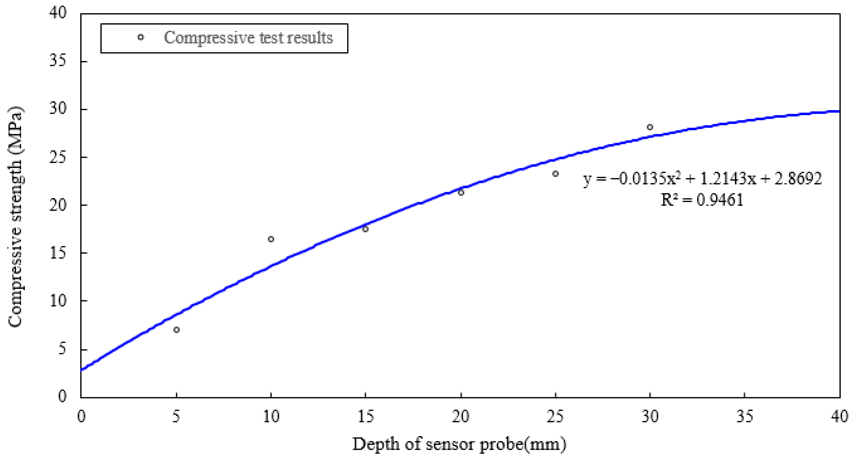
  • The compressive test and FE analysis results demonstrate an increasing trend in compressive strength when the embedment depth increases. The presence of the probe indeed influenced the mortar strength, as the specimen without the probe exhibited the strongest compressive strength. This finding emphasizes the significance of the embedment location of the sensor probe in the development of the compressive strength of mortar. Based on these observations, it is recommended the probe be embedded at a minimum depth of 30 mm from the surface of the mortar structure;
  • Both the experiment and numerical analyses showed that the average compressive strength of the 10 mm specimen was more than twice that of the 5 mm specimen. The relatively rapid failure of the 5 mm specimen was attributed to the concentrated load on the probe caused by embedding the sensor probe too close to the surface of the mortar specimen;
  • The difference between the elastic modulus of the mortar was 28 times that of the sensor probe. Consequently, both the compressive strength test and finite element analysis results confirm that cracks occurred around the probe at the interface of the two materials;
  • A proposed predictive equation was determined based on the test results. This predictive equation can be applied to estimate the compressive strength of mortar when a sensor probe with a nickel-plated copper surface has been buried in mortar comprising ordinary Portland cement if the embedded distance is obtained.
A compressive strength test and FE analysis were conducted by varying the depth of a sensor probe to identify whether the compressive strength of mortar can reach the expected compressive strength when the probe is buried in the mortar for the first time. Based on the results of this study, a sensor probe with a nickel-plated copper surface embedded in the mortar structure can be considered structurally sustainable if the embedded depth is at least 30 mm. Additionally, the outcomes of this study can be utilized as data for reference in further research.

Author Contributions

Conceptualization, J.Y.; methodology, J.K.; software, Y.S.; validation, J.Y.; formal analysis, Y.S.; investigation, C.K.; resources, C.K.; data curation, J.C.; writing—original draft preparation, C.K.; writing—review and editing, J.Y.; visualization, Y.S.; supervision, J.Y.; project administration, J.Y.; funding acquisition, J.Y. All authors have read and agreed to the published version of the manuscript.

Funding

This study was supported by The National Research Foundation of Korea (NRF) grant funded by the Korea government (MSIT) (No. 2021R1F1A10606851222182102130102). Additionally, this study was supported by the 2022 Research Grant from Kangwon National University.

Institutional Review Board Statement

Not applicable.

Informed Consent Statement

Not applicable.

Data Availability Statement

The data that support the findings of this study are available on request from the authors.

Acknowledgments

This work was supported by technical assistance from Geumgang Remi-Con (limited partnership), located in Jecheon-Si, Chungcheongbuk-do, South Korea.

Conflicts of Interest

The authors declare no conflict of interest.

References

  1. Rose, K.; Eldridge, S.; Chapin, L. The internet of things: An overview. Internet Soc. (ISOC) 2015, 80, 1–50. [Google Scholar]
  2. Singh, M.K.; Amin, S.I.; Imam, S.A.; Sachan, V.K.; Choudhary, A. A Survey of Wireless Sensor Network and its types. In Proceedings of the 2018 International Conference on Advances in Computing, Communication Control and Networking (ICACCCN), Greater Noida, India, 12–13 October 2018; pp. 326–330. [Google Scholar] [CrossRef]
  3. Abdelmadjid, M.K.; Noureddine, S.; Amina, B.; Khelifa, B.; Tariq, B.; Boubakeur, L. IoT and WSNs Technology for Control in the Greenhouse Agriculture-Review. In Proceedings of the 2022 3rd International Conference on Embedded & Distributed Systems (EDiS), Oran, Algeria, 2–3 November 2022; pp. 136–141. [Google Scholar] [CrossRef]
  4. Sehrawat, D.; Gill, N.S. Smart sensors: Analysis of different types of IoT sensors. In Proceedings of the 2019 3rd International Conference on Trends in Electronics and Informatics (ICOEI), Tirunelveli, India, 23–25 April 2019; pp. 523–528. [Google Scholar] [CrossRef]
  5. Ojha, T.; Misra, S.; Raghuwanshi, N.S. Wireless sensor networks for agriculture: The state-of-the-art in practice and future challenges. Comput. Electron. Agric. 2015, 118, 66–84. [Google Scholar] [CrossRef]
  6. Ko, J.; Lu, C.; Srivastava, M.B.; Stankovic, J.A.; Terzis, A.; Welsh, M. Wireless sensor networks for healthcare. Proc. IEEE 2010, 98, 1947–1960. [Google Scholar] [CrossRef]
  7. Song, S.; Hou, Y.; Guo, M.; Wang, L.; Tong, X.; Wu, J. An investigation on the aggregate-shape embedded piezoelectric sensor for civil infrastructure health monitoring. Constr. Build. Mater. 2017, 131, 57–65. [Google Scholar] [CrossRef]
  8. Frei, M.; Deb, C.; Stadler, R.; Nagy, Z.; Schlueter, A. Wireless sensor network for estimating building performance. Autom. Constr. 2020, 111, 103043. [Google Scholar] [CrossRef]
  9. Taheri, S. A review on five key sensors for monitoring of concrete structures. Constr. Build. Mater. 2019, 204, 492–509. [Google Scholar] [CrossRef]
  10. Wang, W.; Zhao, K.; Zhang, P.; Bao, J.; Xue, S. Application of three self-developed ECT sensors for monitoring the moisture content in sand and mortar. Constr. Build. Mater. 2021, 267, 121008. [Google Scholar] [CrossRef]
  11. Tang, S.W.; Yao, Y.; Andrade, C.; Li, Z. Recent durability studies on concrete structure. Cem. Concr. Res. 2015, 78, 143–154. [Google Scholar] [CrossRef]
  12. Jedidi, M.; Benjeddou, O. Chemical causes of concrete degradation. MOJ Civ. Eng 2018, 4, 40–46. [Google Scholar] [CrossRef] [Green Version]
  13. Shang, H.-S.; Yi, T.-H. Freeze-thaw durability of air-entrained concrete. Sci. World J. 2013, 2013, 650791. [Google Scholar] [CrossRef] [Green Version]
  14. Lorenzi, A.; Stein, K.; Reginatto, L.A.; Pinto da Silva Filho, L.C. Concrete structures monitoring using ultrasonic tests. Rev. Constr. 2020, 19, 246–257. [Google Scholar] [CrossRef]
  15. Wu, C.; Xiang, H.; Jiang, S.; Ma, S. Stress Monitoring of Concrete via Uniaxial Piezoelectric Sensor. Sensors 2022, 22, 4041. [Google Scholar] [CrossRef]
  16. Chakraborty, J.; Wang, X.; Stolinski, M. Damage detection in multiple RC structures based on embedded ultrasonic sensors and wavelet transform. Buildings 2021, 11, 56. [Google Scholar] [CrossRef]
  17. Du, Z.; Tian, L.; Wang, P.; Chen, Z.; Cui, D.; Jin, Z.; Zhang, H. All-solid-state chloride sensor for in-situ monitoring of chloride penetration in concrete. Constr. Build. Mater. 2022, 357, 129345. [Google Scholar] [CrossRef]
  18. Akamatsu, R.; Sugimoto, T.; Utagawa, N.; Katakura, K. Proposal of non contact inspection method for concrete structures using high-power directional sound source and scanning laser doppler vibrometer. Jpn. J. Appl. Phys. 2013, 52, 07HC12. [Google Scholar] [CrossRef]
  19. Cabezas, J.; Sánchez-Rodríguez, T.; Gómez-Galán, J.A.; Cifuentes, H.; González Carvajal, R. Compact embedded wireless sensor-based monitoring of concrete curing. Sensors 2018, 18, 876. [Google Scholar] [CrossRef] [Green Version]
  20. Kocherla, A.; Duddi, M.; Subramaniam, K.V. Embedded PZT sensors for monitoring formation and crack opening in concrete structures. Measurement 2021, 182, 109698. [Google Scholar] [CrossRef]
  21. Ekaputri, J.J.; Maekawa, K.; Ishida, T. Experimental study on internal RH of BFS mortars at early age. Mater. Sci. Forum 2016, 857, 305–310. [Google Scholar] [CrossRef]
  22. Zhou, H.; Liu, Y.; Lu, Y.; Dong, P.; Guo, B.; Ding, W.; Xing, F.; Liu, T.; Dong, B. In-situ crack propagation monitoring in mortar embedded with cement-based piezoelectric ceramic sensors. Constr. Build. Mater. 2016, 126, 361–368. [Google Scholar] [CrossRef]
  23. Im, H.; Lee, Y.; Inturu, O.; Liu, N.; Lee, S.; Kwon, S.-J.; Lee, H.-S.; Kim, S. A highly sensitive ultrathin-film iron corrosion sensor encapsulated by an anion exchange membrane embedded in mortar. Constr. Build. Mater. 2017, 156, 506–514. [Google Scholar] [CrossRef]
  24. Pan, H.H.; Huang, M.-W. Piezoelectric cement sensor-based electromechanical impedance technique for the strength monitoring of cement mortar. Constr. Build. Mater. 2020, 254, 119307. [Google Scholar] [CrossRef]
  25. Sampaio, R.; Bastos, A.; Ferreira, M. New Sensors for Monitoring pH and Corrosion of Embedded Steel in Mortars during Sulfuric Acid Attack. Sensors 2022, 22, 5356. [Google Scholar] [CrossRef] [PubMed]
  26. Chakraborty, J.; Katunin, A.; Klikowicz, P.; Salamak, M. Early crack detection of reinforced concrete structure using embedded sensors. Sensors 2019, 19, 3879. [Google Scholar] [CrossRef] [Green Version]
  27. Srinivasan, S.; Sudarsan; Taylor, S.E.; Basheer, P.A.M.; Smith, B.J.; Sun, T.; Grattan, K.T.V. Fibre Optic Relative Humidity Sensors for Long-Term Monitoring of Concrete Structures. In Proceedings of the 4th International Conference on Structural Health Monitoring on Intelligent Infrastructure (SHMII-4), Zurich, Switzerland, 22–24 July 2009; pp. 2–11. [Google Scholar]
  28. Martínez-Ibernón, A.; Lliso-Ferrando, J.; Gandía-Romero, J.M.; Soto, J. Stainless steel voltammetric sensor to monitor variations in oxygen and humidity availability in reinforcement concrete structures. Sensors 2021, 21, 2851. [Google Scholar] [CrossRef]
  29. Roopa, A.; Hunashyal, A.M.; Venkaraddiyavar, P.; Ganachari, S.V. Smart hybrid nano composite concrete embedded sensors for structural health monitoring. Mater. Today Proc. 2020, 27, 603–609. [Google Scholar] [CrossRef]
  30. Işık, E.; Harirchian, E.; Bilgin, H.; Kaya, B.; Karaşin, İ.B. The Effect of Insufficient Cover Thickness on Structural Performance of Reinforced Concrete Buildings. In Proceedings of the 30th International Conference on Organization and Technology of Maintenance (OTO 2021), Osijek, Croatia, 8 January 2021; pp. 262–277. [Google Scholar] [CrossRef]
  31. Taylor, H.F.W. Cement Chemistry; Thomas Telford Publishing: London, UK, 1997; pp. 1–2. [Google Scholar]
  32. Paine, K.A. Lea’s Chemistry of Cement and Concrete, 5th ed.; Hewlett, P., Liska, M., Eds.; Butterworth-Heinemann: Oxford, UK, 2019; Chapter 7; pp. 284–339. [Google Scholar]
  33. ASTM C150/150M-21; Standard Specification for Portland Cement. ASTM International: West Conshohocken, PA, USA, 2021.
  34. ASTM C928/928M-20a; Standard Specification for Packaged, Dry, Rapid-Hardening Cementitious Materials for Concrete Repairs. ASTM International: West Conshohocken, PA, USA, 2020.
  35. ASTM C109/109M-21; Standard Test Method for Compressive Strength of Hydraulic Cement Mortars. ASTM International: West Conshohocken, PA, USA, 2021.
  36. ASTM C305-21; Standard Practice for Mechanical Mixing of Hydraulic Cement Pastes and Mortars of Plastic Consistency. ASTM International: West Conshohocken, PA, USA, 2021.
  37. Sensirion. Available online: https://www.sensirion.com/ (accessed on 23 March 2023).
  38. Copper Nickel-Plated Temperature Humidity Sensor Sheath sht10 11 sht20 21 25 15 SHT 30 31 15 sht75 Copper Sintering Cover. Available online: https://www.aliexpress.com/item/1005002771402779.html (accessed on 30 March 2023).
  39. Ma’Mari, F.A.; Moorsom, T.; Teobaldi, G.; Deacon, W.; Prokscha, T.; Luetkens, H.; Lee, S.; Sterbinsky, G.E.; Arena, D.A.; MacLaren, D.A. Beating the Stoner criterion using molecular interfaces. Nature 2015, 524, 69–73. [Google Scholar] [CrossRef] [Green Version]
  40. Wu, X.; Wen, B. A cauliflower-shaped nickel@ porous calcium silicate core-shell composite: Preparation and enhanced electromagnetic shielding performance. Compos. Sci. Technol. 2020, 199, 108343. [Google Scholar] [CrossRef]
  41. ASTM C511-21; Standard Specification for Mixing Rooms, Moist Cabinets, Moist Rooms, and Water Storage Tanks Used in the Testing of Hydraulic Cements and Concretes. ASTM International: West Conshohocken, PA, USA, 2021.
  42. Heungjin. Available online: http://www.heungjin.co.kr/ (accessed on 23 March 2023).
  43. Lubliner, J.; Oliver, J.; Oller, S.; Oñate, E. A plastic-damage model for concrete. Int. J. Solids Struct. 1989, 25, 299–326. [Google Scholar] [CrossRef]
  44. Lee, J.; Fenves, G.L. A plastic-damage concrete model for earthquake analysis of dams. Earthq. Eng. Struct. Dyn. 1998, 27, 937–956. [Google Scholar] [CrossRef]
  45. Thamboo, J.; Dhanasekar, M. Nonlinear finite element modelling of high bond thin-layer mortared concrete masonry. Int. J. Mason. Res. Innov. 2016, 1, 5–26. [Google Scholar] [CrossRef]
  46. Copper Nickel 10%, UNS C70600. Available online: https://www.matweb.com/search/datasheet.aspx?MatGUID=d5133c23a81e4b5cba35a45f8dda6502 (accessed on 1 April 2023).
  47. Arezoodar, A.F.; Baladi, A. The effects of materials properties & angle junction on stress concentration at interface of dissimilar materials. Adv. Mater. Res. 2012, 383–390, 887–892. [Google Scholar] [CrossRef]
Figure 1. Specification of sensor probe employed in this study.
Sustainability 15 10772 g001
Figure 2. Conceptual drawing of mortar cube with embedded sensor probe for compressive strength test.
Sustainability 15 10772 g002
Figure 3. Customized system for fastening sensor probe and controlling embedded depth.
Sustainability 15 10772 g003
Figure 4. Conceptual drawing for producing mortar specimens with predetermined embedded depths of the sensor probe.
Sustainability 15 10772 g004
Figure 5. Customized mortar molds for controlling the embedded depth of the sensor probe.
Sustainability 15 10772 g005
Figure 6. Produced test specimens used to test compressive strength according to the embedded depth of the sensor probe.
Sustainability 15 10772 g006
Figure 7. Finite element modeling with mesh, dimensions, boundary conditions, and loading conditions (ex: embedded depth: 20 mm).
Sustainability 15 10772 g007
Figure 8. Variation according to load in compressive strength test for a 15 mm embedded depth specimen: (a) test set up; (b) after testing; (c) cracks around the embedded sensor probe.
Sustainability 15 10772 g008
Figure 9. Contours of compressive damage variable ( d c ) for various embedded depths: (a) 5 mm; (b) 10 mm; (c) 15 mm; (d) 20 mm; (e) 25 mm; and (f) 30 mm.
Sustainability 15 10772 g009aSustainability 15 10772 g009b
Figure 10. Result comparison between compressive strength test and finite element analysis.
Sustainability 15 10772 g010
Figure 11. Predictive model for mortar compressive strength when the embedded depth of sensor probe is determined.
Sustainability 15 10772 g011
Table 1. Summary of literature review.
Authors (Year)ObjectiveNovelty
Ekaputri et al. (2016) [21]Measuring relative humidityMeasuring the effect of BFS on the internal relative humidity of mortar
Zhou et al. (2016) [22]Monitoring the propagation of cracksReal-time monitoring of crack propagation using a cement-based piezoelectric ceramic sensor
Im et al. (2017) [23]Monitoring the corrosion level of rebars within reinforced concreteMeasuring the level of corrosion by embedding the sensor
Pan and Huang (2020) [24]Measuring mortar strength developmentMonitoring the strength of mortar through PEC sensor and EMI technologies
Sampaio et al. (2022) [25]Monitoring the pH concentration of steel embedded in mortarDeveloping a sensor based on iridium oxide to detect the pH concentration of steel within mortar
Table 2. Chemical composition of cement.
ParameterOrdinary Portland Cement (%)
SiO₂22.5
Fe₂O₃3.6
SO₃2.3
CaO62.9
MgO2.1
Al₂O₃5.2
Table 3. Properties of mortar and sensor probe.
Material PropertiesMortarSensor Probe
Elastic modulus (MPa)5000140,000
Poisson’s ratio ( ν )0.250.35
Function coefficient (α)1.121-
Dilation angle (°)10-
Eccentricity of the plastic flow (ϵ)0.1-
Ratio of the tensile to the compressive meridian ( K c )0.667-
Viscosity parameter (μ)0.01-
Table 4. Comparison of compressive strength test results.
Embedded Depth of the Probe (mm)Compressive Strengths of Test Specimens (MPa)
Specimen #1Specimen #2Specimen #3Standard Deviation
58.3806.5446.3440.92
1016.16615.24418.1801.23
1516.46018.76817.3600.95
2020.02822.61221.2761.06
2522.18424.18023.7480.86
3028.29626.74429.4721.12
Non-embedded28.91430.39529.9420.62
Disclaimer/Publisher’s Note: The statements, opinions and data contained in all publications are solely those of the individual author(s) and contributor(s) and not of MDPI and/or the editor(s). MDPI and/or the editor(s) disclaim responsibility for any injury to people or property resulting from any ideas, methods, instructions or products referred to in the content.

