Article

Research on Energy Absorption Characteristics of Bouligand Biomimetic Structure Based on CFRP Composite Materials

1
Faculty of Civil Engineering and Mechanics, Kunming University of Science and Technology, Kunming 650500, China
2
Faculty of Science, Kunming University of Science and Technology, Kunming 650500, China
*
Author to whom correspondence should be addressed.
Sustainability 2023, 15(13), 9911; https://doi.org/10.3390/su15139911
Submission received: 17 April 2023 / Revised: 17 June 2023 / Accepted: 19 June 2023 / Published: 21 June 2023

Abstract

:
Enhancing the impact resistance performance of carbon fiber-reinforced polymer (CFRP) laminates stands as a prominent research focus among various nations. Existing studies have shown a tendency towards arbitrary selection of the inter-ply helix angle values in CFRP laminates, which is accompanied by a limited number of samples representing the chosen helix angles. However, existing studies have shown a relatively random selection of spiral angle values between CFRP laminates, and the sample size of selected spiral angles is limited, posing certain limitations. In order to tackle this problem, we have employed a systematic arrangement of combinations to select the optimal helix angle for CFRP laminates. Inspired by the biological structures of Bouligand, we have sequentially chosen 19 distinct sets of helix angles, aiming to overcome the inherent limitations and enhance the research outcomes in this field. In this study, we established 19 finite element models to investigate the behavior of Bouligand-inspired CFRP composite panels under high-velocity bullet impact. The models were created by selecting 19 sets of helix angles within the range of 0 to 90° with a 5° interval. The results show that the energy absorption of the Bouligand layer-stacking composite plate is better than that of the conventional plate. The optimal spiral angles of the CFRP laminate are 25° and 30°, and the energy absorption characteristics of the laminate are the best at these angles. The impact resistance is also the best at these angles. The energy absorption of the Bouligand layer-stacking composite plate is 396% higher in absorbed internal energy and 361% higher in absorbed kinetic energy compared to the conventional layer-stacking composite plate, significantly improving the ballistic performance of the CFRP bulletproof material and providing a reference for the design of individual protection equipment.

1. Introduction

1.1. Overview of CFRP Materials

Carbon fiber-reinforced polymer (CFRP) is a high-performance composite material composed of carbon fibers and thermosetting resins, which finds widespread applications in aviation, automotive, sports equipment, and ballistic protection. In the field of ballistic protection, CFRP is used as a bulletproof material, and its ballistic performance depends on factors such as the strength and density of carbon fibers, and the bonding strength and fracture toughness of the resin [1,2,3,4]. Due to its lightweight, high strength, high modulus, and corrosion resistance, as well as the ability to provide a high bulletproof capability with a thinner thickness, CFRP has broad prospects in the design of lightweight individual ballistic protection equipment [4,5,6,7].
The ballistic performance of CFRP bulletproof materials depends on the strength and density of their carbon fibers. The strength of carbon fibers is 6−12 times higher than that of steel, while the density is only 20−25% of that of steel [7,8,9,10,11,12]. Therefore, at the same thickness, CFRP bulletproof materials can provide a higher bulletproof capability than steel. Moreover, carbon fibers have excellent tensile properties and stiffness, which can effectively resist bullet loads and improve the ballistic performance. When used in combination with high-strength ceramics, CFRP can enhance the hardness and stiffness of the bulletproof material. CFRP can withstand the tensile and shear forces of the bullet load, enabling it to effectively absorb the bullet load and thus improve the ballistic performance [12]. When combined with steel plates, CFRP can also balance the ballistic performance and rigidity of the material, thereby improving its bulletproof capability and overall strength. Additionally, CFRP bulletproof materials can be further enhanced through special treatments, such as surface treatment and heat treatment [13].

1.2. Application of CFRP in the Field of Protection

The application of carbon fiber-reinforced polymer (CFRP) as a bulletproof material in the field of ballistic protection has a significant history. For instance, during World War II, the United States Air Force employed lightweight materials similar to CFRP to produce aircraft components, replacing traditional metal materials. These components not only achieved a weight reduction but also possessed a certain ballistic performance [14,15,16,17,18]. To investigate the mechanical properties of CFRP in resisting penetration, numerous domestic and foreign scholars have conducted experiments such as drop hammer tests and air cannon tests. They have not only studied the factors that affect the anti-penetration performance of CFRP laminates, such as target plate composition materials, lamination methods, thickness, boundary conditions, and projectile shape, mass, and size, but also researched the anti-penetration mechanism and energy absorption mechanism of the target plate under different conditions [18,19,20,21,22,23].
Cantwell and Morton [24] conducted experimental research on the response and penetration of CFRP simply supported beams and fixed circular plates under projectile impact using drop hammer and air cannon devices. The research results indicated that the main energy dissipation mechanisms of CFRP beams under low-speed impact were elastic deformation, delamination, and shear fracture, and the energy absorption capacity of the beam increased with its length. Under high-speed impact conditions, the penetration energy of the beam did not change significantly with the change of the beam length, mainly manifested as local response and damage. Lee and Sun [25] conducted experimental and numerical simulation research on the response and penetration of CFRP laminates under flat-headed projectile penetration and concluded that interlayer delamination and shear plugging were the main damage modes. Goldsmith et al. [26] carried out experimental and theoretical analyses of the response of a planar-woven CFRP composite laminate with different thicknesses to conical projectile penetration under impact conditions. Ulven et al. [27] investigated the perforation mechanism, ballistic limit, and damage evolution process of woven CFRP composite laminates under ballistic impact conditions. The laminates were subjected to impact by different-shaped projectiles, such as flat-headed, spherical, conical, and fragment simulating projectiles. The research revealed that the influence of the projectile shape on CFRP laminates under high-speed impact was consistent with the theoretical analysis model proposed by Wen [28,29].
Therefore, CFRP, as a high-performance reinforced composite material, has broad application prospects in the field of ballistic protection and can play an important role in the lightweight design of individual ballistic protection equipment. With the development of technology, CFRP ballistic materials have been widely used in the design of lightweight ballistic protection equipment, such as bulletproof vests, ballistic helmets, and ballistic shields.

1.3. Common CFRP Lamination Angles

CFRP laminates are composite materials composed of multiple layers of carbon fiber fabric or prepreg. They are formed by stacking multiple layers of carbon fiber fabric with resin layers and undergoing curing and heating processes [30,31,32,33]. CFRP laminates are processed by vacuum-assisted molding, where single layers of fiber sheets are overlaid at specific angles. The selection of fiber layer angles during the lamination process has different effects on the mechanical properties and load distribution of the entire CFRP laminate. Based on the required performance and design specifications of different structures, appropriate lamination angles are chosen [34,35,36,37].
Commonly used lamination angles include 0°, 45°, and 90° [32,33,35,37]. In addition to these common angles, other angles can be selected to meet specific requirements. For example, setting the lamination angle to 30 degrees or 60 degrees can provide support when the CFRP material is subjected to tension or shear. Therefore, different lamination angles can provide different strengths and stiffness in different directions, resulting in an improved structural performance and load distribution. In practical applications, combinations of multiple lamination angles are often employed to fully utilize the anisotropic properties of CFRP materials and meet the requirements of different engineering structures [38,39].
However, when considering the protective performance of CFRP, the choice of lamination strategy and method is crucial. Determining the appropriate angles and arranging them in a suitable manner can enhance the energy absorption capacity of CFRP laminates, which is the focus of this study.

1.4. Overview of Bouligand Structure

Biological materials are essential to meet the basic survival and developmental requirements of human beings, playing irreplaceable roles in agriculture, industry, and military fields [40,41,42,43,44,45,46]. In fact, most biological materials are composed of multiple components, such as composites consisting of collagen, silk, keratin, and other proteins [47]. The characteristic dimensions of these materials range from the microscale to the macroscale, forming the hard and soft structures of organisms at complex hierarchical levels, such as the multifunctional dermal armor found in fish, some reptiles, and mammals [48]. These structures typically consist of layered structures of collagen fibers connecting rigid scales/bones and skin, serving functions such as body protection, temperature regulation, and food capture [49].
In 1972, Bouligand [50] observed the arc-shaped and bow-shaped fiber forms of various crustaceans using optical microscopy and electron microscopy and concluded that the periodic patterns were formed by the stacking of regularly arranged fiber layers, each layer rotated a small angle relative to the previous layer, forming a helical arrangement. For example, the mantis shrimp, which uses the Bouligand helical structure in its appendages, can attack prey at speeds of 14–23 m per second [51]. In addition to its extremely high speed, the mantis shrimp’s joint for resisting damage is similar to a hammer, capable of withstanding thousands of high-strength impacts. This is because the mantis shrimp’s appendages are made of materials with Bouligand structures (Figure 1), with chitin fibers in each layer, and each layer offset relative to the adjacent layer, forming a helical stacking structure [41]. Some Bouligand structures in arthropods are composed of multiple composite materials, such as crystalline hydroxyapatite containing fibrous organic matrices and various materials such as amorphous calcium phosphate arranged in layered spiral tissues. These layered structures can effectively prevent biological tissues from being damaged when subjected to multiple high loads (usually exceeding 200N [51]).
For example, fish scales are usually composed of a hard protective outer layer and a flexible inner layer, providing the fish with strong maneuverability and defense capabilities, and enabling the fish to effectively bear local stress and concentrated loads [48,49,50]. Similar structures have also been found in the bodies of nearly extinct coelacanth [52]. These natural protective units have different shapes and forms, but they all demonstrate relatively low density, lightweight, high strength, strong energy absorption, as well as high protection, maneuverability, and flexibility.

1.5. Overview of Bouligand Structure

To enhance the energy absorption characteristics and protective effectiveness of composite materials, researchers have attempted to apply the Bouligand biomimetic structure to bulletproof composite materials for exploring the design and engineering of spiral curve structure topology. The researchers focused on conducting experiments such as uniaxial tension, flat bending, three-point bending, low-velocity impact, and post-impact compression tests on composite laminates. In addition, D. Ginzburg et al. compared the impact resistance and energy absorption properties of Bouligand-arranged [53] CFRP laminates with those of ordinary CFRP laminates, cross-type CFRP laminates, and quasi-isotropic CFRP laminates using LVI tests and LS-DYNA finite element low-speed impact simulations. They found that the impact resistance and energy absorption properties of CFRP laminates arranged in the Bouligand structure were the best.
Xingyuan Zhang et al. [54] compared the deformation, damage, and energy absorption properties of this composite material with those of single-helix-laminated structural materials under bending loads using experiments and numerical simulations. The analysis results showed that the spiral-laminated structure can improve the stress distribution during deformation and damage, achieve high load transmission efficiency, alleviate local stress concentration, and delay material failure to solve the problem of insufficient strength and toughness. Yumin An et al. [55] prepared carbon fiber/ceramic films with Bouligand-like structures using the SPS method and tested the performance of the bionic ceramics. The fracture toughness was 7.4 MPa∙m0.5, and the fracture energy was 1055 J/m2. Yuan Zhang et al. [56] theoretically analyzed the different configurations of the Bouligand structure, and based on this, they manufactured a novel tungsten-copper composite material with a tungsten fiber-braided structure. The mechanical properties and oxidation resistance of the new tungsten-copper composite material were significantly improved, and its strength was high, with good ductility at high temperatures. The study also found that the double-layer Bouligand structure was the most effective layering method, which promoted coordinated deformation, reduced local damage, and induced crack twisting between layers. Lorenzo Mencattelli and Silvestre T. Pinho [57] manufactured ultra-thin carbon fiber-reinforced plastic (CFRP) composite laminates based on the Bouligand structure, and selected five different stacking angles of 2.5°, 5°, 10°, 20°, and 45° for full-permeability, quasi-static indentation tests and in situ three−point bending tests. The analysis results showed that the ultra-thin CFRP composite laminates with smaller stacking angles had better structural integrity and a higher load-bearing capacity. Wenting Ouyang et al. [58] theoretically analyzed the mechanical properties of carbon fiber-laminated structures and the rotational pitch of the Bouligand structure and compared the theoretical model with the experimental results of 32-layer spiral carbon fiber. They selected four layer−spacing angles of 6°, 9.1°, 12°, and 25.7°, and found that 9.1° was the optimal angle for arranging the carbon fiber laminates. The carbon fiber laminates arranged at 9.1° had the highest load-carrying capacity and the best energy absorption effect.

1.6. Limitations of the Current Study

However, numerous studies on the spiral angle of the Bouligand structure in CFRP laminates have predominantly focused on the variations following low-velocity impact on the laminates. Foreign researchers have extensively investigated low-velocity simulation experiments and simulations for multilayer CFRP laminates but there is limited research on damage patterns in laminates under high-velocity impact. Furthermore, the selection of spiral angle values between laminate layers has been relatively arbitrary, with a limited number of chosen spiral angles, highlighting insufficient systematic exploration of spiral angle formation in Bouligand structures. Addressing these concerns, this study aims to explore the optimal spiral angle within the range of 0 to 90° for carbon fiber/epoxy resin (CFRP) composite ballistic materials based on the Bouligand biomimetic structure. The findings will provide valuable insights for the design of modern layered carbon fiber composite ballistic vests and individual ballistic protection equipment.

2. Model and Damage Criterion

2.1. Verification of Model Validity

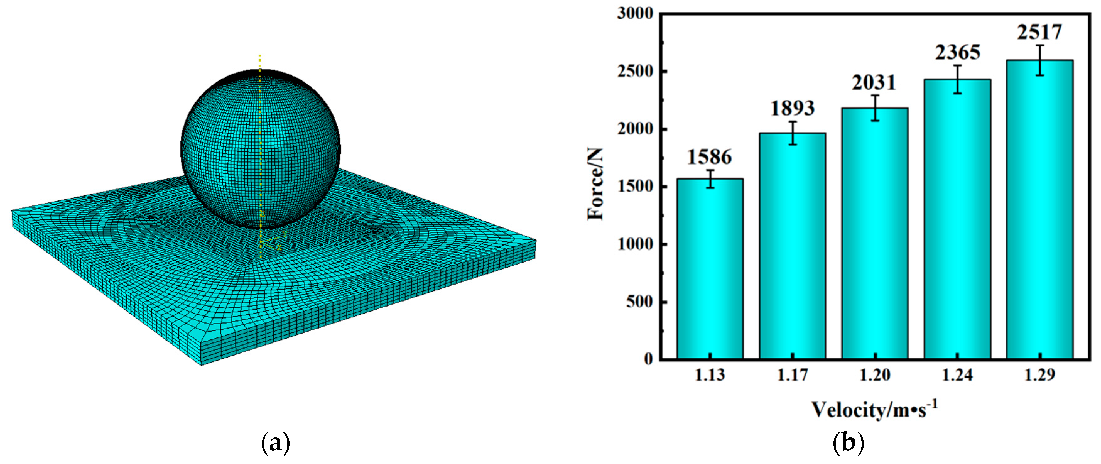
This study is based on the composite material-laminated plate impact model presented in [59]. The same CFRP (TT300/QY3911) model and layup angle (0°/90°) were adopted, and five impact velocities (1.13 m/s, 1.17 m/s, 1.20 m/s, 1.24 m/s, 1.29 m/s) were simulated to compare the simulation results with the maximum contact force test results in the original literature to verify the validity of the model. The data error did not exceed 10% of the obtained results. The obtained data calculations and comparison results are shown in Figure 2b and Table 1. To further improve the accuracy of the model, this study established a finite element impact model for a 10-layer Bouligand bio−inspired, composite−laminated plate with different helical angles based on the original model. In this model, the fiber thickness of each layer was 0.5 mm, and an adhesive layer was set between each layer based on the B-K damage criterion.

2.2. Preliminary Modeling Process

This study utilized the Abaqus finite element simulation software to establish a multi-layered CFRP ballistic composite material model subject to bullet impact. The laminated panel is composed of carbon fiber-reinforced epoxy composite material (CFRP), with each layer of composite material fiber thickness at 0.5 mm and a total of 10 layers with the same thickness. A 9 mm bullet head with a diameter of 14.14 mm and a height of 17.61 mm was set as a rigid body, and the RP-1 was set as the reference point of the 9 mm bullet head. The axial velocity of 900 m/s was applied to the reference point, and the layered panel size was 200 mm × 200 mm, with a total thickness of 5 mm. The models of the layered panel and the bullet head are shown in Figure 3a,c, respectively. To ensure both the accuracy and efficiency of the finite element model, the mesh division follows the symmetric axial approach, as described in [59]. The element type adopted was C3D8R hexahedral elements. The mesh density of the laminate plate gradually decreased outward from the impact point of the projectile, while the central region employed refined mesh treatment. Based on the division along the mesh axis, a suitable size for the central cubic mesh was 2.3 mm × 2.3 mm × 0.5 mm. A mesh size larger than 2.3 mm in the central area would affect the experimental accuracy, causing excessive distortion of the laminate portion and consequently halting the experiment. Conversely, a mesh size smaller than 2.3 mm would significantly impact the computational speed and computer storage requirements. Therefore, a central mesh size of 2.3 mm × 2.3 mm × 0.5 mm was the optimal choice. The Hashin failure criteria were used to simulate the damage and failure process of the CFRP composite-laminated panel. The cohesive element was used to simulate the interlayer cohesive force behavior, and the general contact was applied between the bullet and the layered panel. In addition, complete fixed constraints were adopted for the four sides of the cube-shaped target board, and the first contact position of the bullet head and the target board was set at the center of the layered panel, with the bullet head perpendicular to the front surface of the panel. The explicit dynamics analysis was conducted with a total step length of 0.15 ms (1 ms = 1 × 10⁻³ s).

2.3. The Hashin 3D Criterion for Fiber-Reinforced Composites

2.3.1. Hashin Damage Criteria

Fiber-reinforced composite materials are layered materials composed of fibers and a matrix [60,61,62,63]. The fibers mainly provide resistance to penetration, while the matrix functions by bonding the fibers and inducing layer failure at the interface to achieve energy absorption. In practice, single-layer plate failure gradually occurs as stress increases, damage expands, and the load reaches its limit, ultimately resulting in fracture. Due to the anisotropy of fiber-reinforced composite materials and other factors, failure modes generally fall into two categories: fiber failure and matrix failure [64,65]. In this study, the Hashin 3D failure criterion was used for the simulation, which follows four failure criteria, and the damage expression of the fiber damage model used in this study is based on the strain-dependent Hashin failure criterion [59,66], expressed as follows:
Fiber tensile failure based on strain description:
F f T = σ ^ X T + α S C 2 σ ^ 12 2 + σ ^ 13 2 1
Fiber compression failure based on strain description:
F f C = σ ^ 11 X T 2 1
Matrix tensile failure based on strain description:
F m T = σ ^ 22 + σ ^ 33 Y T + σ ^ 23 2 σ ^ 11 σ ^ 11 S T 2 + σ ^ 12 2 + σ ^ 13 2 S 2 C 1
Matrix compression fracture based on strain description:
F m C = σ ^ 22 + σ ^ 33 2 S T 2 + Y C 2 S C 1 σ ^ 22 + σ ^ 33 Y C + σ ^ 23 2 σ ^ 22 σ ^ 33 S T 2 + σ ^ 12 2 + σ ^ 13 2 S C 2 1
In the equation, α is the shear correction factor, σ ^ i j is the stress component in different directions of the material, YC represent the strengths of transverse compression, YT represent the strengths of transverse tension, XT represent the strengths of fiber axial tension, XC represent the strengths of axial compression, ST represent the strengths of transverse shear, and SC represent the strengths of axial shear, respectively, for carbon fiber-reinforced polymer (CFRP) composite material, as shown in Table 2. Where ρ represents the density of the material, E1 denotes the elastic modulus in the X-direction, E2 represents the elastic modulus in the Y-direction, and µ12 denotes the Poisson’s ratio of the material. During the high-speed impact on composite laminates, there is a significant strain rate effect, which needs to be considered in the strength parameters. The model assumes that the strain rate effect on the strength in each direction of the composite single-layer laminate can be uniformly represented as:
S = S 0 + C ln ε ˙ ε 0 ˙
In the equation, S0 is the reference strain rate, S is the strength under the current strain rate, ε ˙ represents the equivalent strain rate, ε 0 represents the strength parameter, and C is the strain rate correction factor for the corresponding strength.

2.3.2. Quads Damage Criteria

In this study, the initiation criterion of the cohesive element’s damage was based on the quadratic stress criterion, namely the Quads Damage criterion, and the damage evolution followed the energy-based B-K criterion. The Quads Damage criterion, which is expressed by a mathematical formula, was adopted as the initiation criterion for damage in this study. The selection of specific parameters for the adhesive unit is shown in Table 3. Among them, Enn, σn, and GI represent the separation stiffness, damage initiation stress, and fracture energy in the normal direction, while Ess, σs, and GII represent the separation stiffness, damage initiation stress, and fracture energy in the first shear direction. Ett, σt, and GIII represent the separation stiffness, damage initiation stress, and fracture energy in the second shear direction. The numerical values of all parameters are shown in Table 3.
Meanwhile, the failure equation of the Quads Damage criterion is:
σ n N m a x 2 + σ s S m a x 2 + σ t T m a x 2 = 1
In the equation, σn is the nominal stress under the main stress of n, σs is the nominal stress in the first shear direction, and σt is the nominal stress in the second shear direction. Nmax, Smax, and Tmax are the maximum fracture strength of the material, and when the above equation is true, it is determined that the material has been damaged.

3. Numerical Simulation Analysis

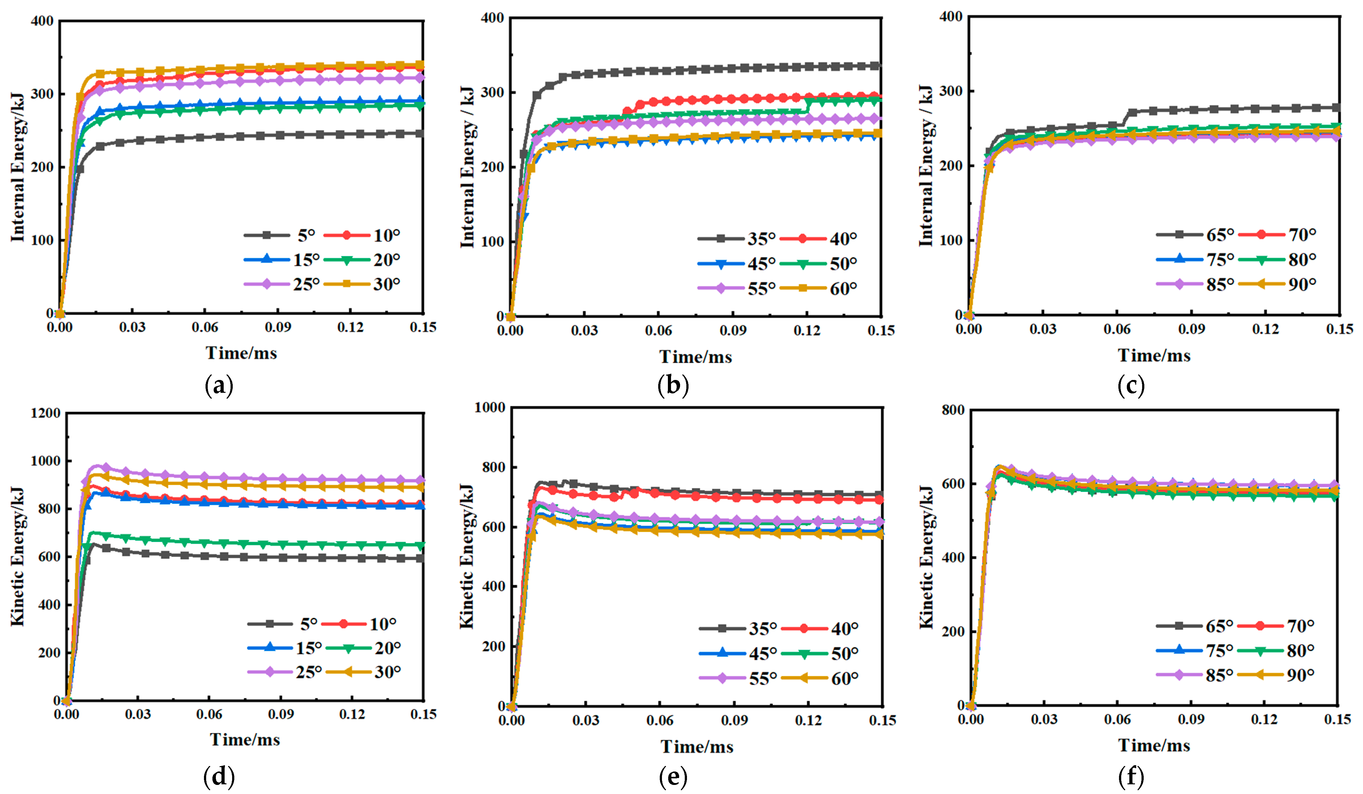
In search of the optimal helix angle, we selected 18 helix angles within the range of 0 to 90°, with increments of 5 degrees as the standard. The 18 angles were divided into 3 groups, with 6 angles in each group. The first group comprised of helix angles of 5°, 10°, 15°, 20°, 25°, and 30°. The second group comprised of helix angles of 35°, 40°, 45°, 50°, 55°, and 60°. The third group comprised of helix angles of 65°, 70°, 75°, 80°, 85°, and 90°. A comparison was made with the CFRP-laminated plate with no helix angle (0°) to investigate the changes in the internal energy and kinetic energy of the CFRP-laminated plate as a whole when subjected to bullet impact, as well as the displacement (U3) of the laminated plate in the opposite direction of bullet impact. The changes in internal energy and kinetic energy within the three groups are shown in Figure 4a−f.
We found that within the range of 5 to 30°, the internal energy of the laminated plate was minimized at θ = 5° and maximized at θ = 30°. Similarly, the magnitude of kinetic energy absorbed by the laminated plate still showed a nonlinear relationship with the helix angle. The minimum kinetic energy absorption occurred at θ = 5°, while the maximum occurred at θ = 25°. Within the range of 35° to 60°, the internal energy was minimized at θ = 50°, while the maximum internal energy absorption occurred at θ = 35°.
The minimum kinetic energy absorption occurred at θ = 60°, while the maximum kinetic energy absorption occurred at θ = 35°. Within the range of 65 to 90°, the minimum internal energy absorption occurred at θ = 85°, while the maximum internal energy absorption occurred at θ = 65°. The maximum kinetic energy absorption occurred at θ = 85°, and the minimum kinetic energy absorption occurred at θ = 80°, indicating that the energy absorption of CFRP-laminated plates with different Bouligand helix angle structures displayed randomness under high-speed bullet impact.
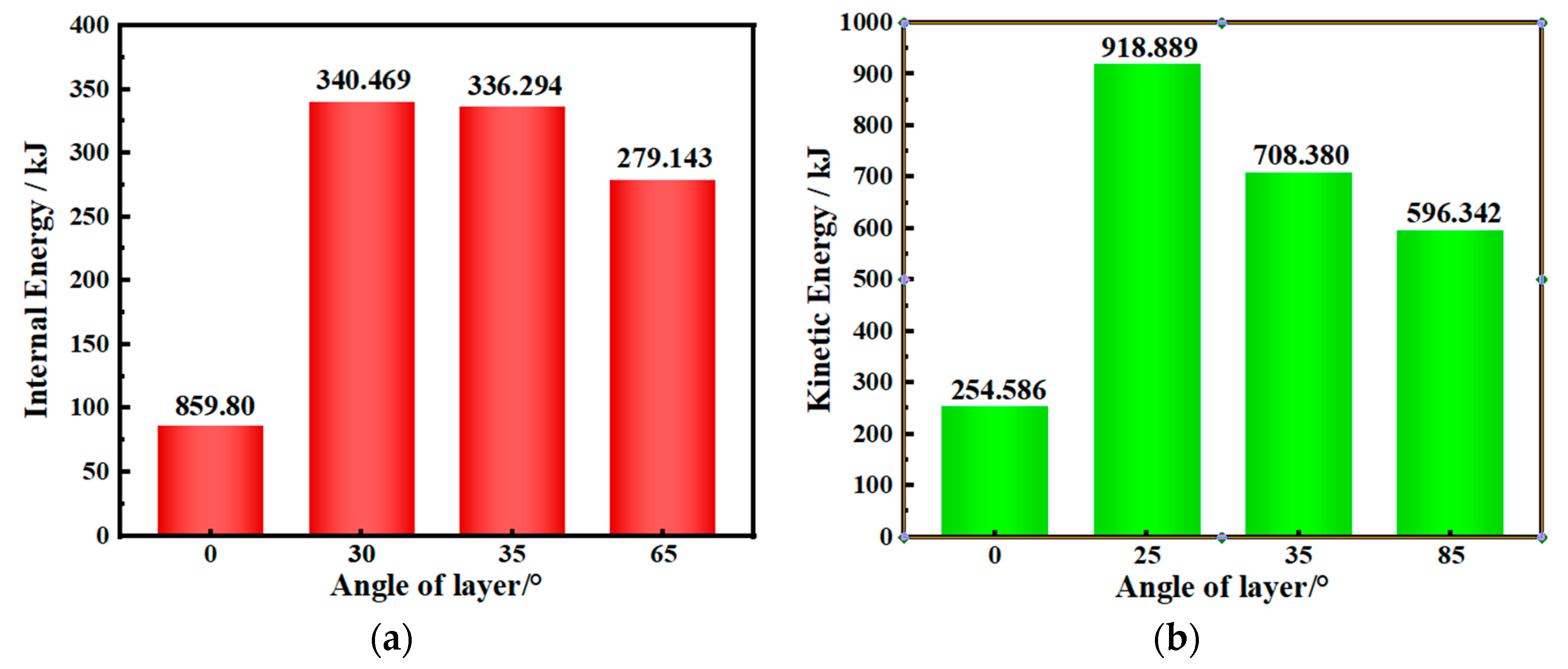
As the helix angle increased, the energy absorption effect of the first group’s (0–30°) laminated plate was the best, while the third group’s (65–90°) laminated plate had a poorer energy absorption effect. The internal and kinetic energy of the laminated plate showed a decreasing trend with the increase of the helix angle. Within each group, the relationship between the internal energy absorbed by the CFRP-laminated plate and the helix angle was nonlinear, as was the relationship between the kinetic energy absorbed and the helix angle. Intra-group analysis revealed a nonlinear relationship between the internal energy and the spiral angle of the CFRP laminate as the angle increased. Simultaneously, the dynamic energy exerted on the CFRP laminate also exhibited a nonlinear relationship with the spiral angle. These observations indicate that subtle variations in the spiral angle did not exhibit a discernible pattern, consistent with the findings reported in [68]. In this study, we compared the methods for evaluating internal energy and kinetic energy as described in [53,57], respectively. We conducted a comparative analysis by comparing the internal energy and kinetic energy variations of three groups of laminates with the unidirectional CFRP laminate (with a helix angle of 0°) that lacked additional layers. The results, as shown in Figure 5a,b, indicated that the energy absorption efficiency and impact resistance of the CFRP-laminated veneer arranged according to the helix angle arewere superior to those without layering.
The internal energy of the CFRP-laminated veneer without layering was 859.80 kJ, while the best energy-absorbing CFRP-laminated veneer (helix angle of 30°) received 340.469 kJ of internal energy, an increase of 396% compared to the internal energy of the laminated veneer without layering. Moreover, the kinetic energy produced by the CFRP-laminated veneer without layering was 254.586 kJ, whereas the best energy-absorbing CFRP-laminated veneer (helix angle of 25°) received 918.889 kJ of internal energy, an increase of 361% compared to the kinetic energy produced by the laminated veneer without layering. The energy absorption effect was significant.
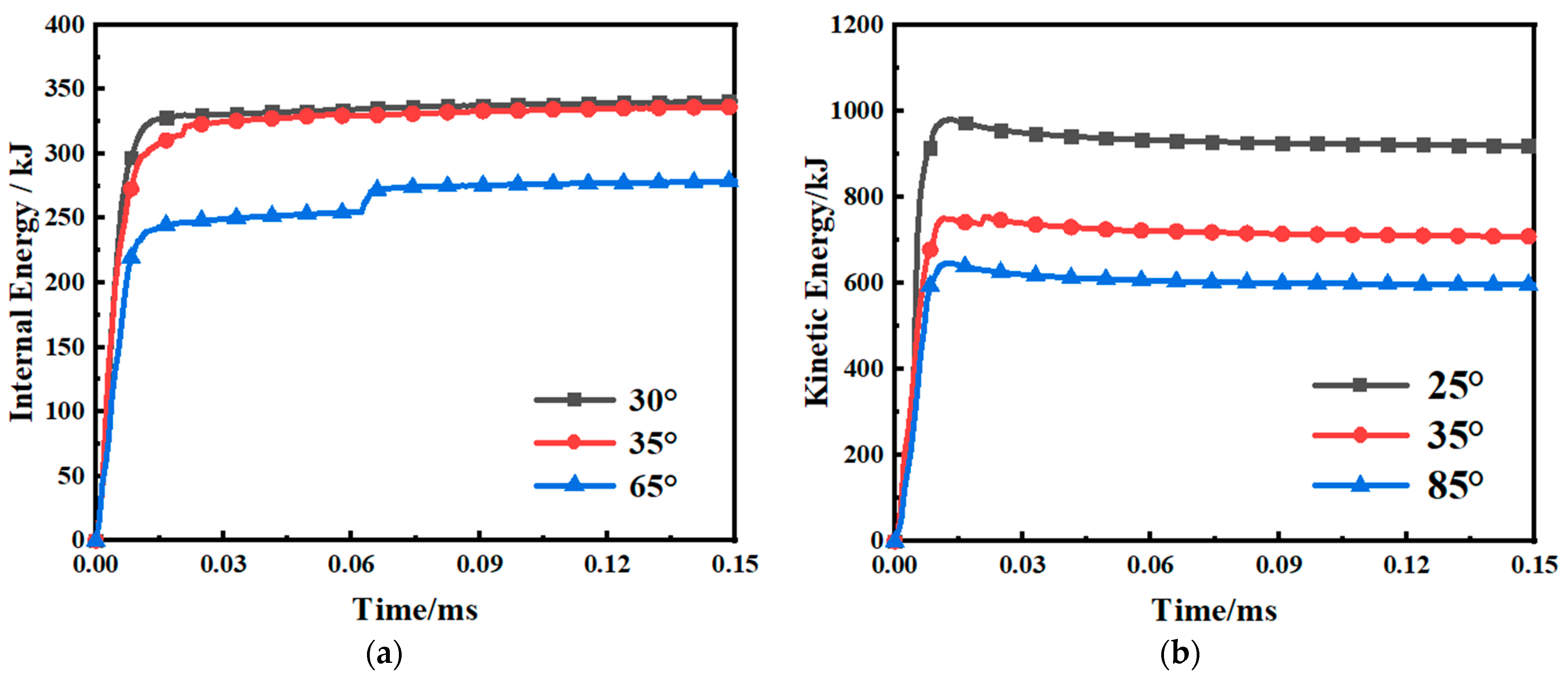
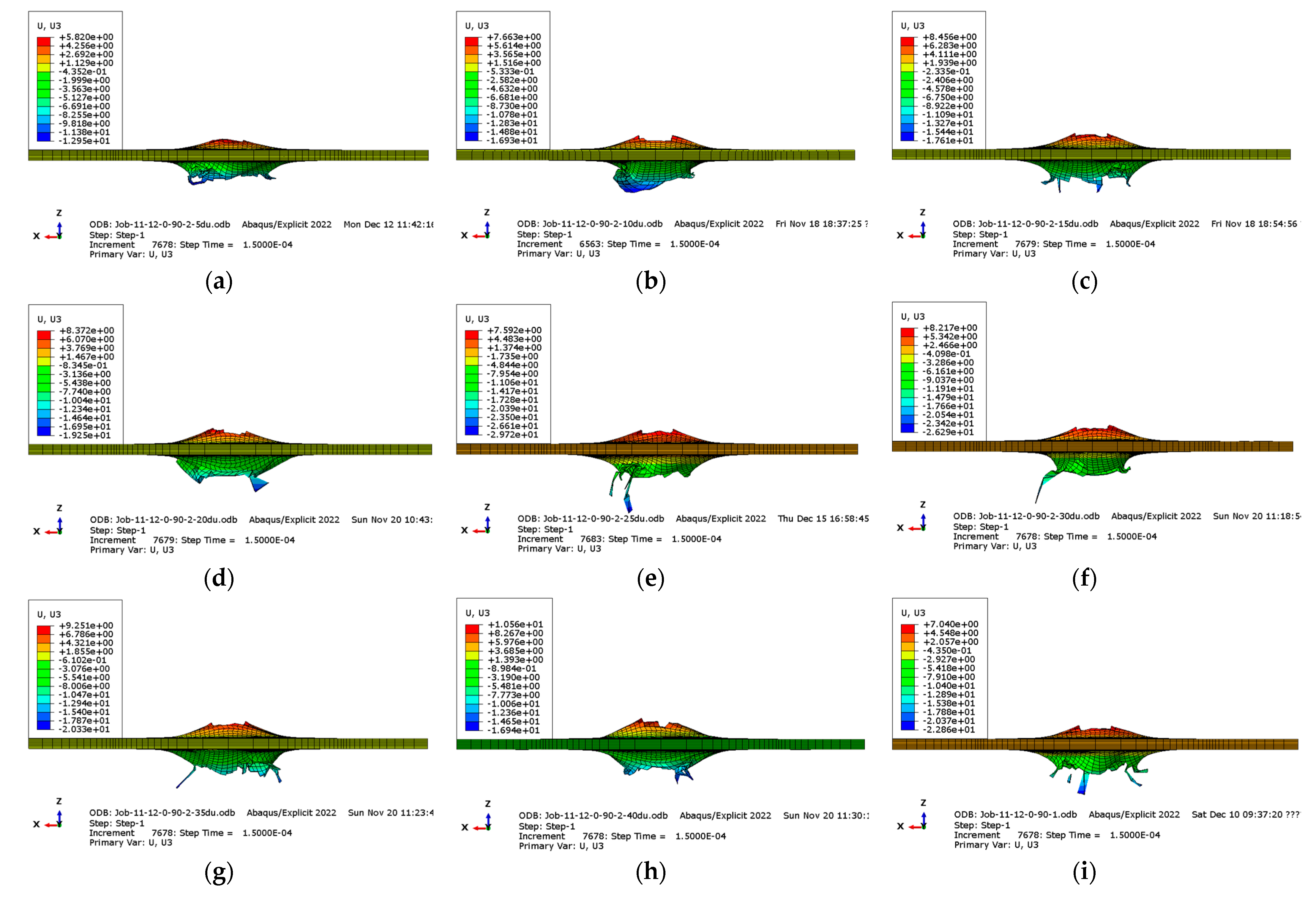
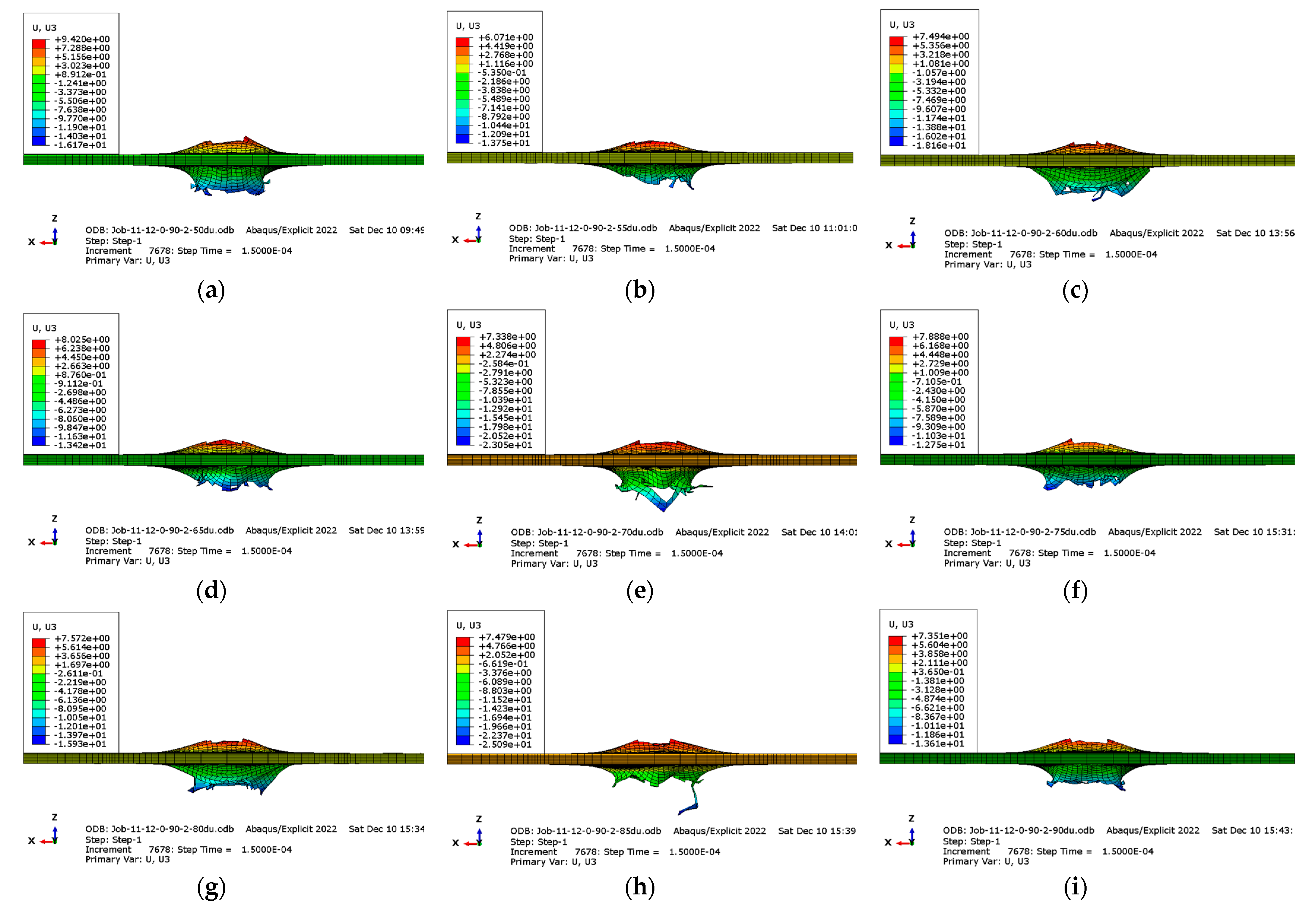
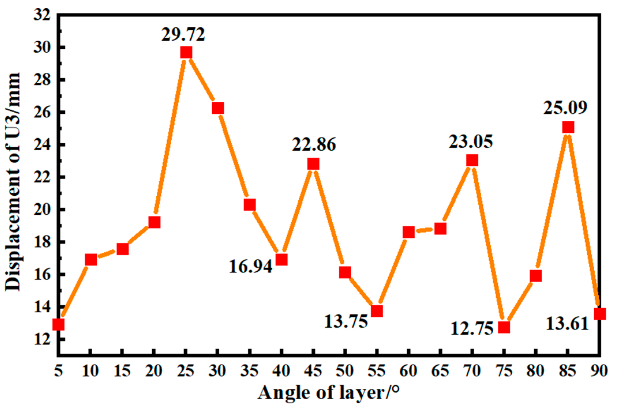
Comparing the laminated veneer with the highest changes in internal energy and kinetic energy in each group, as shown in Figure 6a,b, we found that the laminated veneer with a helix angle of 30° had the highest internal energy in the 0–90° range, while the CFRP-laminated veneer with a helix angle of 25° had the highest kinetic energy, indicating that the CFRP-laminated veneer with helix angles of 25°and 30° exhibited the best energy absorption characteristics and impact resistance. Meanwhile, the axial displacement cloud maps of 18 sets of laminated veneer panels within the ranges of 5−45°and 50−90°helix angles are depicted in Figure 7 and Figure 8, respectively. A comparative analysis of the maximum axial displacements from Figure 7 and Figure 8 yields a generated maximum displacement cloud map, illustrating the relationship between helix angle variations and maximum displacements, as presented in Figure 9. In our study, we have made a noteworthy observation regarding the fluctuation of axial displacement values in laminated composite panels as a function of angle. Peaks in displacement were observed at 25°, 45°, 70°, and 85°, with corresponding magnitudes of 29.72 mm, 22.86 mm, 23.05 mm, and 25.09 mm, respectively. Conversely, minima in displacement occurred at 5°, 40°, 55°, 75°, and 90°, measuring 12.97 mm, 16.94 mm, 13.75 mm, 12.75 mm, and 13.61 mm, respectively. Additionally, within the range of 5° to 25°, the axial displacement of the laminated composite panels increased as the helix angle increased.
However, within the range of 25° to 40°, the axial displacement decreased with an increasing helix angle. The laminated composite panels exhibited their maximum displacement at helix angles of 25° and 30°, measuring 29.72 mm and 26.29 mm, respectively. Moreover, the laminated composite panels exhibited the highest axial displacement at a helix angle of 25°, measuring 29.72 mm. Subsequently, a helix angle of 25° resulted in a slightly lower axial displacement of 26.75 mm. This suggests that laminated composite panels with helix angles of 25° and 30° underwent significant interactions, such as transverse shearing and axial extension, following impact from the same kinetic energy. These interactions contributed to the larger reverse displacement observed in laminated composite panels with helix angles of 25° and 30°. The obtained results align with the findings presented in Figure 6a,b, indicating that ten-layer CFRP-laminated composite panels with helix angles of 25° and 30° can withstand a greater amount of energy. This consistency supports the previous literature [68], which suggests that lower layer count CFRP-laminated composite panels exhibit optimal helix angles. Therefore, the ten-layer CFRP-laminated composite panels fabricated using these two angles demonstrate excellent energy absorption properties, making them highly effective in resisting bullet impact.

4. Conclusions

In the context of high-speed impact, the increase and decrease of the spiral angle and the corresponding energy absorption capacity exhibited a nonlinear relationship in the 0°–90° range of carbon fiber-reinforced polymer (CFRP) laminates. However, within a certain range of angles, there may exist certain regularities. In terms of the energy absorption efficiency, laminates with a Bouligand structure exhibited a superior overall energy absorption capacity compared to conventional laminates. The best-performing Bouligand laminate exhibited a 396% increase in absorbed internal energy and a 361% increase in absorbed kinetic energy compared to the conventional laminate. Furthermore, among the Bouligand CFRP laminates, those with a spiral angle of 25° and 30° demonstrated a higher resistance to penetration than those with other angles. The laminates with a spiral angle of 25° and 30° exhibited the best energy absorption properties and the highest resistance to impact.
The aforementioned phenomenon elucidates that CFRP laminates, when arranged following the biomimetic structure of brittle stars, exhibit a significant improvement in energy absorption characteristics and protective efficacy, without altering any material properties. This biomimetic placement strategy for CFRP laminates offers superior impact resistance properties, thereby showcasing its potential to enhance the overall performance of the laminated structure. Furthermore, the findings of this study may stimulate further research in the fields of the defense industry and other related domains, aiming to maximize the enhancement of the protective performance of the composite materials. Additionally, it could pave the way for the production and practical application of the Bouligand biomimetic spiral-laminated plates.

Author Contributions

Conceptualization, Z.X.; methodology, D.L.; software, Z.X. and J.D.; validation, Z.X. and J.D.; formal analysis, Z.X.; investigation, W.X. and D.L.; resources, D.L.; data curation, Z.X. and W.X.; writing—original draft preparation, J.D.; writing—review and editing, Z.X. and D.L. All authors have read and agreed to the published version of the manuscript.

Funding

This research received no external funding.

Institutional Review Board Statement

Not applicable.

Informed Consent Statement

Not applicable.

Data Availability Statement

Details on all data supporting the reported results can be obtained in Table 1, Table 2 and Table 3 and Figure 1, Figure 2, Figure 3, Figure 4, Figure 5, Figure 6, Figure 7, Figure 8 and Figure 9 of this original manuscript.

Conflicts of Interest

No potential conflict of interest was reported by the authors.

References

  1. González, E.V.; Maimí, P.; Martín-Santos, E.; Soto, A.; Cruz, P.; Martín de la Escalera, F.; Sainz de Aja, J.R. Simulating drop-weight impact and compression after impact tests on composite laminates using conventional shell finite elements. Int. J. Solids Struct. 2018, 144–145, 230–247. [Google Scholar] [CrossRef]
  2. Byar, A.D.; Pang, J.K.; Iqbal, J.; Ko, J.; Rassaian, M. Determination of Ballistic Limit for IM7/8552 Using LS-DYNA. In Proceedings of the 2018 AIAA SciTech Forum, Kissimmee, FL, USA, 8–12 January 2018; p. 11. [Google Scholar]
  3. Nassiraei, H.; Rezadoost, P. SCFs in tubular X-connections retrofitted with FRP under in-plane bending load. Compos. Struct. 2021, 274, 114314. [Google Scholar] [CrossRef]
  4. Melis, M.; Pereira, M.; Goldberg, R.K.; Rassaian, M. Dynamic Impact Testing and Model Development in Support of NASA’s Advanced Composites Program. In Proceedings of the 2018 AIAA/ASCE/AHS/ASC Structures, Structural Dynamics, and Materials Conference, Kissimmee, FL, USA, 8–12 January 2018; American Institute of Aeronautics and Astronautics: Kissimmee, FL, USA, 2018. [Google Scholar]
  5. Nassiraei, H.; Rezadoost, P. Static capacity of tubular X-joints reinforced with fiber reinforced polymer subjected to compressive load. Eng. Struct. 2021, 236, 112041. [Google Scholar] [CrossRef]
  6. Hoffarth, C.; Khaled, B.; Rajan, S.D.; Goldberg, R.; Carney, K.; DuBois, P.; Blankenhorn, G. Using Tabulated Experimental Data to Drive an Orthotropic Elasto-Plastic Three-Dimensional Model for Impact Analysis. In Proceedings of the LS-DYNA International Conference, Detroit, MI, USA, 14–16 May 2014. [Google Scholar]
  7. Ogihara, S.; Takeda, N.; Kobayashi, S.; Kobayashi, A. Effects of stacking sequence on microscopic fatigue damage development in quasi-isotropic CFRP laminates with interlaminar-toughened layers. Compos. Sci. Technol. 1999, 59, 1387–1398. [Google Scholar] [CrossRef]
  8. Hoffarth, C.; Khaled, B.; Shyamsunder, L.; Rajan, S.D. Development of a Tabulated Material Model for Composite Material Failure, MAT213: Part 1: Theory, Implementation, Verification & Validation; U.S. Department of Transportation, Federal Aviation Administration: Washington, DC, USA, 2020.
  9. Shyamsunder, L.; Khaled, B.; Rajan, S.D.; Pereira, J.M.; DuBois, P.; Blankenhorn, G. Numerical validation of composite panel impact tests. Int. J. Impact Eng. 2022, 159, 104032. [Google Scholar] [CrossRef]
  10. Meola, C.; Carlomagno, G.M. Infrared thermography of impact-driven thermal effects. Appl. Phys. A 2009, 96, 759–762. [Google Scholar] [CrossRef]
  11. Meola, C.; Carlomagno, G.M. Impact damage in GFRP: New insights with infrared thermography. Compos. Part. Appl. Sci. Manuf. 2010, 41, 1839–1847. [Google Scholar] [CrossRef]
  12. Amiri, M.; Khonsari, M.M. Life prediction of metals undergoing fatigue load based on temperature evolution. Mater. Sci. Eng. A 2010, 527, 1555–1559. [Google Scholar] [CrossRef]
  13. Meola, C.; Carlomagno, G.M. Infrared thermography to evaluate impact damage in glass/epoxy with manufacturing defects. Int. J. Impact Eng. 2014, 67, 1–11. [Google Scholar] [CrossRef]
  14. Boccardi, S.; Carlomagno, G.M.; Simeoli, G.; Russo, P.; Meola, C. Evaluation of impact-affected areas of glass fibre thermoplastic composites from thermographic images. Meas. Sci. Technol. 2016, 27, 075602. [Google Scholar] [CrossRef]
  15. Koyanagi, J.; Mochizuki, A.; Higuchi, R.; Tan, V.B.C.; Tay, T.E. Finite element model for simulating entropy-based strength-degradation of carbon-fiber-reinforced plastics subjected to cyclic loadings. Int. J. Fatigue 2022, 165, 107204. [Google Scholar] [CrossRef]
  16. Lawrence Sy, B.; Oguamanam, D.; Bougherara, H. Impact response of a new kevlar/flax/epoxy hybrid composite using infrared thermography and high-speed imaging. Compos. Struct. 2022, 280, 114885. [Google Scholar] [CrossRef]
  17. Goto, K.; Arai, M.; Kano, Y.; Hara, E.; Ishikawa, T. Compressive fracture aspect of thick quasi-isotropic carbon fiber reinforced plastic laminates. Compos. Sci. Technol. 2019, 181, 107706. [Google Scholar] [CrossRef]
  18. Kramer, S.L.B.; Tighe, R. (Eds.) Conference Proceedings of the Society for Experimental Mechanics Series; Springer International Publishing: Cham, Switzerland, 2021; pp. 99–104. [Google Scholar]
  19. Ogihara, S.; Takeda, N.; Kobayashi, S.; Kobayashi, A. Damage mechanics characterization of transverse cracking behavior in quasi-isotropic CFRP laminates with interlaminar-toughened layers. Int. J. Fatigue 2002, 24, 93–98. [Google Scholar] [CrossRef]
  20. Roberts-Wollmann, C.L.; Kreger, M.E.; Rogowsky, D.M.; Breen, J.E. Stresses in External Tendons at Ultimate. ACI Struct. J. 2005, 102, 206–213. [Google Scholar]
  21. Tian, D.; Zhou, X. A continuum-kinematics-inspired peridynamic model of anisotropic continua: Elasticity, damage, and fracture. Int. J. Mech. Sci. 2021, 199, 106413. [Google Scholar] [CrossRef]
  22. Yamada, Y.; Iwata, K.; Kadowaki, T.; Sumiya, T. Method of reduced variables for stiffness degradation process of unidirectional CFRP composites subjected to alternating bending. Compos. Sci. Technol. 2017, 138, 117–123. [Google Scholar] [CrossRef]
  23. Pinho, S.T.; Iannucci, L.; Robinson, P. Physically based failure models and criteria for laminated fibre-reinforced composites with emphasis on fibre kinking. Part II: FE implementation. Compos. Part. Appl. Sci. 2006, 37, 766–777. [Google Scholar] [CrossRef]
  24. Cantwell, W.J.; Morton, J. Impact perforation of carbon fibre reinforced plastic. Compos. Sci. Technol. 1990, 38, 119–141. [Google Scholar] [CrossRef]
  25. Lee, S.W.R.; Sun, C.T. Dynamic penetration of gahite/epoxy laminates impacted byablunt-ended projectil. Compos. Sci. Technol. 1993, 49, 369–380. [Google Scholar] [CrossRef]
  26. Goldsmith, W. Dharan CKH and Chang H. Quasi-static and ballsi perfration of carbonfiber laminates. Int. J. Solids Struct. 1995, 32, 89–103. [Google Scholar] [CrossRef]
  27. Ulven, C.; Vaidya, U.K.; Hosur, M.V. Efect of prjctile shape during baliii pefrationo of VARTM carbon/epoxy composite panels. Compos. Struct. 2003, 61, 143–150. [Google Scholar] [CrossRef]
  28. Wen, H.M. Preicting the pentraion and peforarion of FRP laminates struck normally by pojectles with dffrer nose shapes. Compos. Struct. 2000, 49, 321–329. [Google Scholar] [CrossRef]
  29. Wen, H.M. Penetration and perfration of thick FRP laminates. Compos. Sci. Technol. 2001, 61, 1163–1172. [Google Scholar] [CrossRef]
  30. Sokolović, N.M.; Gavrilović-Grmuša, I.; Zdravković, V.; Ivanović-Šekularac, J.; Pavićević, D.; Šekularac, N. Flexural Properties in Edgewise Bending of LVL Reinforced with Woven Carbon Fibers. Materials 2023, 16, 3346. [Google Scholar] [CrossRef] [PubMed]
  31. Kim, J.S.; Kim, S.J.; Min, K.J.; Choi, J.C.; Eun, H.S.; Song, B.K. A Study on Tensile Behavior According to the Design Method for the CFRP/GFRP Grid for Reinforced Concrete. Materials 2022, 15, 357. [Google Scholar] [CrossRef]
  32. Zhang, J.; Rao, J.; Ma, L.; Wen, X. Investigation of the Damping Capacity of CFRP Raft Frames. Materials 2022, 15, 653. [Google Scholar] [CrossRef]
  33. Abdellah, M.Y.; Zuwawi, A.-R.; Azam, S.A.; Hassan, M.K. A Comparative Study to Evaluate the Essential Work of Fracture to Measure the Fracture Toughness of Quasi-Brittle Material. Materials 2022, 15, 4514. [Google Scholar] [CrossRef]
  34. Khozeimeh, M.A.; Fotouhi, R.; Moazed, R. Static and Vibration Analyses of a Composite CFRP Robot Manipulator. J. Compos. Sci. 2022, 6, 196. [Google Scholar] [CrossRef]
  35. Ge, F.; Lin, Y.; Zhang, F.; Zhang, Z.; Wang, M. Crushing Characteristics Comparison between Aluminum/CFRP and Aluminum/CFRP/Aluminum Hybrid Tubes. Polymers 2022, 14, 4034. [Google Scholar] [CrossRef]
  36. Abdellah, M.Y.; Hassan, M.K.; AlMalki, A.-A.; Mohamed, A.F.; Backar, A.H. Finite Element Modelling of Wear Behaviors of Composite Laminated Structure. Lubricants 2022, 10, 317. [Google Scholar] [CrossRef]
  37. Rao, K.S.; Varadarajan, Y.; Rajendra, N. Erosive Wear Behaviour of Carbon Fiber-reinforced Epoxy Composite. Mater. Today Proc. 2015, 2, 2975–2983. [Google Scholar] [CrossRef]
  38. Korim, N.S.; Abdellah, M.Y.; Dewidar, M.; Abdelhaleem, A.M. Crushable finite element modeling of mechanical properties of titanium foam. Int. J. Sci. Eng. Res. 2015, 6, 1221–1227. [Google Scholar]
  39. Abdellah, M.Y. Essential work of fracture assessment for thin aluminium strips using finite element analysis. Eng. Fract. Mech. 2017, 179, 190–202. [Google Scholar] [CrossRef]
  40. Fabritius, H.O.; Sachs, C.; Triguero, P.R.; Raabe, D. Influence of structural principles on the mechanics of a biological fiber-based composite material with hierarchical organization: The exoskeleton of the lobster Homarus americanus. Adv. Mater. 2009, 21, 391–400. [Google Scholar] [CrossRef]
  41. Grunenfelder, L.K.; Suksangpanya, N.; Salinas, C.; Milliron, G.; Yaraghi, N.; Herrera, S.; Evans-Lutterodt, K.; Nutt, S.R.; Zavattieri, P.; Kisailus, D. Bio-inspired impact-resistant composites. Acta Biomater. 2014, 10, 3997–4008. [Google Scholar] [CrossRef]
  42. Whitney, J. Structural Analysis of Laminated Anisotropic Plates; CRC Press: Lancaster, PA, USA, 1987. [Google Scholar]
  43. Alqam, M.; Alkhairi, F.; Naaman, A. An Improved Methodology for the Prediction of the Stress at Ultimate in Unbonded Internal and External Steel Tendons. Arab. J. Sci. Eng. 2020, 45, 7915–7954. [Google Scholar] [CrossRef]
  44. Wegst, U.G.K.; Ashby, M.F. The mechanical efficiency of natural materials. The mechanical efficiency of natural materials. Phil. Mag. 2004, 84, 2167–2186. [Google Scholar] [CrossRef]
  45. Apichattrabrut, T.; Ravi-Chandar, K. Helicoidal composites. Mech. Adv. Mater. Struct. 2006, 13, 61–76. [Google Scholar] [CrossRef]
  46. Mencattelli, L.; Pinho, S.T. Realising bio-inspired impact damage-tolerant thin-ply CFRP Bouligand structures via promoting diffused sub-critical helicoidal damage. Compos. Sci. Technol. 2019, 182, 107684. [Google Scholar] [CrossRef]
  47. Mencattelli, L.; Pinho, S.T. Herringbone-bouligand cfrp structures: A new tailorable damage-tolerant solution for damage containment and reduced delaminations. Compos. Sci. Technol. 2020, 190, 108047. [Google Scholar] [CrossRef]
  48. Yang, W.; Chen, I.H.; Mckittrick, J.; Meyers, M.A. Flexible Dermal Armor in Nature. JOM 2012, 64, 475–485. [Google Scholar] [CrossRef]
  49. Luz, G.M.; Mano, J.F. Biomimetic design of materials and biomaterials inspired by the structure of nacre. Philos. Trans. A Math. Phys. Eng. Sci. 2009, 367, 1587–1605. [Google Scholar] [CrossRef] [PubMed]
  50. Bouligand, Y. Twisted fifibrous arrangements in biological materials and cholesteric mesophases. Tissue Cell 1972, 4, 189–217. [Google Scholar] [CrossRef] [PubMed]
  51. Weaver, J.C.; Milliron, G.W.; Miserez, A.; Evans-Lutterodt, K.; Herrera, S.; Gallana, I.; Mershon, W.J.; Swanson, B.; Zavattieri, P.; DiMasi, E.; et al. The stomatopod dactyl club: A formidable damage-tolerant biological hammer. Science 2012, 336, 1275–1280. [Google Scholar] [CrossRef] [Green Version]
  52. Giraud, M.M.; Castanet, J.; Meunier, F.J.; Bouligand, Y. The fifibrous structure of coelacanth scales: A twisted ‘Plywood’. Tissue Cell. 1978, 10, 671–686. [Google Scholar] [CrossRef]
  53. Ginzburg, D.; Pinto, F.; Iervolino, O.; Meo, M. Damage tolerance of bio-inspired helicoidal composites under low velocity impact. Compos. Struct. 2017, 161, 187–203. [Google Scholar] [CrossRef] [Green Version]
  54. Xingyuan, Z.; Zhen, W.; Yongcun, L.; Yunbo, L.; Zhang, Q. Improved strength and toughness of bioinspired Bouligand architecture composite by discontinuous carbon fiber. J. Phys. Conf. Ser. 2021, 1906, 012030. [Google Scholar]
  55. An, Y.; Yang, Y.; Jia, Y.; Han, W.; Cheng, Y. Mechanical properties of biomimetic ceramic with Bouligand architecture. J. Am. Ceram. Soc. 2022, 105, 2385–2391. [Google Scholar] [CrossRef]
  56. Yuan, Z.; Guoqi, T.; Mingyang, Z.; Qin, Y.; Zengqian, L.; Yanyan, L.; Jian, Z.; Da, J.; Faheng, W.; Longchao, Z.; et al. Bioinspired tungsten-copper composites with Bouligand-type architectures mimicking fish scales. J. Mater. Sci. Technol. 2022, 96, 21–30. [Google Scholar]
  57. Lorenzo, M.; Silvestre, T.P. Ultra-thin-ply CFRP Bouligand bio-inspired structures with enhanced load-bearing capacity, delayed catastrophic failure and high energy dissipation capability. Pinho Compos. Part A 2020, 129, 105655. [Google Scholar]
  58. Ouyang, W.; Gong, B.; Wang, H.; Scarpa, F.; So, B.; Peng, H.X. Identifying optimal rotating pitch angles in composites with Bouligand structure. Compos. Commun. 2021, 23, 100602. [Google Scholar] [CrossRef]
  59. Xu, S.; Chen, P.H. Prediction of low velocity impact damage in carbon–epoxy laminates. Compos. Part A Appl. Sci. Manuf. 2002, 33, 361. [Google Scholar] [CrossRef] [Green Version]
  60. Nuruzzaman, D.M.; Chowdhury, M.A.; Rahaman, M.L. Effect of duration of rubbing and normal load on friction coefficient for polymer and composite materials. Ind. Lubr. Tribol. 2011, 63, 320–326. [Google Scholar] [CrossRef]
  61. Mohagheghian, I.; Wang, Y.; Zhou, J.; Yu, L.; Guo, X.; Yan, Y.; Charalambides, M.N.; Dear, J.P. Deformation and damage mechanisms of laminated glass windows subjected to high velocity soft impact. Int. J. Solids. Struct. 2017, 109, 46. [Google Scholar] [CrossRef]
  62. Palomar, M.; Lozano-Mínguez, E.; Rodríguez-Millán, M.; Miguélez, M.H.; Giner, E. Relevant factors in the design of composite ballistic helmets. Compos. Struct. 2018, 201, 49. [Google Scholar] [CrossRef]
  63. Heimbs, S.; Heller, S.; Middendorf, P.; Hähnel, F.C.; Weiße, J. Low velocity impact on CFRP plates with compressive preload:test and modelling. Int. J. Impact. Eng. 2009, 36, 1182–1193. [Google Scholar] [CrossRef] [Green Version]
  64. Schwab, M.; Todt, M.; Tauchner, J.; Schlie, D.; Pettermann, H.E. Modeling, simulation, and experiments of high velocity impact on laminated composites. Compos. Struct. 2018, 205, 42. [Google Scholar] [CrossRef]
  65. Duarte, A.; Herszberg, I.; Paton, R. Impact resistance and tolerance of interleavedtape laminates. Compos. Struct. 1999, 47, 753–758. [Google Scholar] [CrossRef]
  66. Hashin, Z. Failure criteria for unidirectional fiber composites. J. Appl. Mech. 1980, 47, 329–334. [Google Scholar] [CrossRef]
  67. Shor, O.; Vazir, R. Adaptive insertion of cohesive elements for simulation of delamination in laminated composite materials. Eng. Fract. Mech. 2015, 146, 121–138. [Google Scholar] [CrossRef] [Green Version]
  68. Ahmed, G.H.; Aziz, O.Q. Shear Strength of Joints in Precast Posttensioned Segmental Bridges During 1959–2019, Review and Analysis. Structures 2019, 20, 527–542. [Google Scholar] [CrossRef]
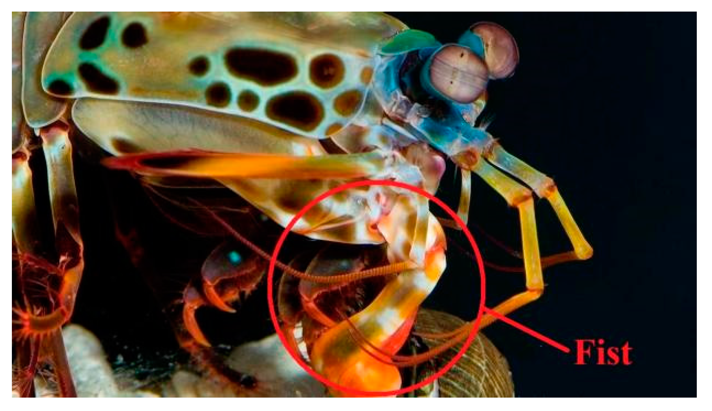
Figure 1. Bird-tailed mantis shrimp hunting parts. Sketch Map.
Sustainability 15 09911 g001
Figure 2. (a) Schematic diagram of the built model. (b) Schematic diagram of maximum contact force at different speeds.
Sustainability 15 09911 g002
Figure 3. (a) Nine millimeter bullet nose model, (b) enlarged contact point, and (c) bullet head—10-layer target model. (The dotted yellow line in the figure is the reference line).
Sustainability 15 09911 g003
Figure 4. (a) The 5−30° internal energy change curve, (b) 35–60° internal energy change curve, and (c) 65−90° internal energy change curve. (d) Kinetic energy change curve of 5−30°, (e) kinetic energy change curve of 35−60°, and (f) kinetic energy change curve of 65−90°.
Sustainability 15 09911 g004
Figure 5. (a) Internal energy parameters of laminates with four different spiral angles. (b) Kinetic energy parameters of laminates with four different spiral angles.
Sustainability 15 09911 g005
Figure 6. (a) Internal energy variation curves of laminates with three angles. (b) Variation curves of kinetic energy of laminate spiral with three spiral angles.
Sustainability 15 09911 g006
Figure 7. (ai) Axial displacement nebulae of CFRP laminates with spiral angles of 5−45°, from smallest to largest in alphabetical order.
Sustainability 15 09911 g007
Figure 8. (ai) Axial displacement nebulae of CFRP laminates with spiral angles of 50−90°, from smallest to largest in alphabetical order.
Sustainability 15 09911 g008
Figure 9. Displacement parameters of laminates with different spiral angles.
Sustainability 15 09911 g009
Table 1. Comparison of maximum contact forces under five different impact speeds.
Impact Velocity (m·s−1)Experimental Maximum Force (N)Simulated Maximum Force (N)Average Error (%)
1.13160815672.55
1.17184019656.79
1.20198621839.92
1.24224724318.19
1.29250125973.84
Table 2. Mechanical property parameters of CFRP (TT300/QY3911) carbon/epoxy composite laminate [50].
ParameterNumerical ValueParameterNumerical ValueParameterNumerical Value
E1/MPa138,000E2/MPa9040µ120.305
G12/MPa4710G13/MPa4710G23/MPa4000
YC/MPa202YT/MPa71.4XC/MPa1188
XT/MPa1696S1/MPa102S2/MPa90
ρ/(t∙m−3)2.7 × 10−9
Table 3. Performance parameters of cohesive elements of composite laminates [67].
ParameterNumerical ValueParameterNumerical ValueParameterNumerical Value
Enn/MPa3000Ess/MPa1154Ett/MPa1154
σn20σs25σt25
GI0.249GII0.733GIII0.733
σs25σt25GI0.249
Disclaimer/Publisher’s Note: The statements, opinions and data contained in all publications are solely those of the individual author(s) and contributor(s) and not of MDPI and/or the editor(s). MDPI and/or the editor(s) disclaim responsibility for any injury to people or property resulting from any ideas, methods, instructions or products referred to in the content.