Abstract
To study the standardized evaluation method of vibration comfort of pedestrian bridges, the effect of the transient response term is ignored based on the generalized single degree of freedom (SDOF) method with reference to the American Institution of Steel Construction inc (AISC 11) specification. The resonance conditions between the crowd and the bridge structure are also considered, and the pedestrian bridge structure is simplified to an SDOF system. Then, the peak acceleration of the structure under crowd excitation is directly calculated using the generalized crowd load, and the comfort evaluation is carried out according to the German EN03 code and the Chinese code. For a new pedestrian bridge with hinged piers, human-induced vibration tests were carried out to obtain the structural acceleration time response data under various crowd load excitation conditions, and the acceleration values calculated with the numerical simulation method, the frequency response function method, the generalized SDOF method, and the proposed method were compared with field measurements. The results show that for the normal excitation condition with a crowd density less than or equal to 0.2 person/m2, the acceleration maximum error for the proposed method is between 4.22% and 13.28%. The error is only 6.35% compared with the finite element simulation results. The method can derive peak acceleration by performing only modal tests, eliminating errors caused by different testers and errors due to deflection measurements. It saves considerable time cost and economic cost, and improves the speed of pedestrian bridge comfort evaluation. Therefore, the method proposed for the first time in this study can accurately assess the human-caused vibration comfort of pedestrian bridges with articulated piers. Although the hinged-pier and column steel pedestrian bridge meets the code requirement of a vertical first-order frequency greater than 3 Hz, it is recommended to add TMD vibration damping measures to the bridge in order to improve pedestrian comfort.
1. Introduction
The considerations inherent to pedestrian bridge design often result in structures that are elongated and slender in shape. Due to the smaller size of the structural elements, pedestrian bridges are often much more flexible and have a lower natural frequency of vibration than that of vehicular bridges.
The difference in natural frequencies between pedestrian and vehicular bridges is important because it can impact the bridge’s response to external loads or environmental factors such as wind and earthquakes. It is essential to consider these differences in design to ensure the safety and sustainability of the bridges.
When pedestrians walk on these structures, it is common for large vibrations to occur, which may cause discomfort and even dizziness, particularly in more severe cases. For this reason, pedestrian bridges usually require a human vibration comfort test or assessment before their opening to ensure their serviceability.
The design of pedestrian bridges is mainly based on crowd loads. Various countries have developed mathematical models to account for both static and dynamic impacts of crowds on bridge structures in the vertical and transverse directions. These models are applied during the design phase to accurately describe the effects of crowds and ensure specific reliability guarantees. Some of these codes even include classifications for pedestrian comfort levels. In 1996, China issued Technical Specifications for Urban Footbridges, Pedestrian Overcrossing, and Pedestrian Underpasses (CJJ69-95) [1], which systematically outlined criteria for ensuring the comfort of footbridges. One particular criterion in the document requires footbridges to maintain a vertical self-vibration frequency above 3 Hz. Furthermore, other nations have established guidelines regarding the vibration comfort of buildings and pedestrian bridges. The European code JRC [2], British code (BS5400) [3], and German code (EN03) [4], for example, have all specified the vertical natural frequency and vibration acceleration requirements for these structures, as well as other indicators. Complying with EN03 guidelines, the acceleration of a bridge during crowd resonance must be evaluated when the vertical and longitudinal vibrations’ first- and second-order frequencies are between 1.25 to 2.3 Hz and 2.5 to 4.6 Hz, respectively, and the transverse vibration frequency is between 0.5 and 1.2 Hz. According to the provisions in BS 5400, if the fundamental frequency of the superstructure is above 5 Hz when the bridge is unloaded, the bridge satisfies the criteria for human-induced vibration comfort. In instances where the fundamental frequency of the superstructure is equal to or less than 5 Hz, the maximum vertical vibration acceleration of any section of the superstructure shall not exceed 0.5 f0 (where f0 refers to the fundamental frequency of the bridge). As a preliminary draft for review, the Technical Specifications for Urban Pedestrian Over-Crossing and Underpass [1] outline the vibration comfort requirements for footbridges. These regulations encompass various factors such as natural frequency, vibration acceleration limitations, and damping ratios.
Apart from the specifications mentioned, several approaches have been proposed for gauging the comfort level of pedestrian bridges. Dallard [5] conducted acceleration measurements on the Millennium Bridge in London and proposed a method to calculate the lateral vibration response at a high crowd density, so as to determine the lateral acceleration. Li and Chen [6] developed a time domain analysis method that incorporates a random walking force load model to calculate the human-induced vibration response based on a modal analysis. This approach effectively confirms both the reliability and sustainability of human-induced vibration for pedestrian bridges, after taking randomness into account. Xie et al. [7] validated the accuracy of a pedestrian load model based on two legs, while proposing a numerical method that considers the coupling effect between humans and bridges. They confirmed that the two-legged model can more accurately simulate the characteristics of pedestrian footstep force. Some of them are based on design formulas for single-degree-of-freedom approximations [8,9,10]. In specific scenarios, a more thorough approach is advised, which involves utilizing detailed structural or numerical models to assess the interaction between humans and the structure.
Zhu et al. [11] developed a method using frequency response functions (FRF) to quickly assess the level of human-induced vibration comfort of pedestrian bridges by calculating the peak acceleration in the span under various loading conditions. Their method enables the assessment of pedestrian bridges’ comfort levels, considering both frequency and peak acceleration. However, its reliance on costly and non-standardized in situ testing with pedestrian loads could potentially lead to deviations in measurement outcomes.
In order to seek a standardized approach for the vibration comfort evaluation of pedestrian bridges, an improved SDOF evaluation method is proposed based on the generalized SDOF method with reference to the AISC 11 [12] specification. Human-induced vibration tests were carried out for a new pedestrian bridge with hinged piers to obtain the structural acceleration time history under various crowd-loading cases. Subsequently, numerical simulations were conducted to determine the range of acceleration time results. Acceleration values acquired through the numerical simulation, frequency response function (FRF) method, generalized SDOF method, and improved SDOF method, respectively, were compared with field test data, and the errors fell within acceptable margins, thereby validating the proposed method.
2. Project Overview
A new steel pedestrian bridge with hinged piers was built for Dali railway station in 2022, as shown in Figure 1. The box girder is composed of two spans: a main span of 37 m and a side span of 13 m, plus two additional cantilevers of 3.25 and 3 m, respectively, resulting in a total length of 56.25 m. The bridge deck width is 4.5 m. Piers Z1 and Z3 are all fixed to the superstructure, but their bottom ends are connected to the pile caps through hinges to allow for rotational movement of the piers in the transverse direction. Pier Z2 and the girder are connected using a plate rubber bearing (GBZY350x63).Acceleration and displacement transducers used in the test site, as shown in Figure 2. Detail drawing of a pedestrian bridge with hinged piers, as shown in Figure 3.
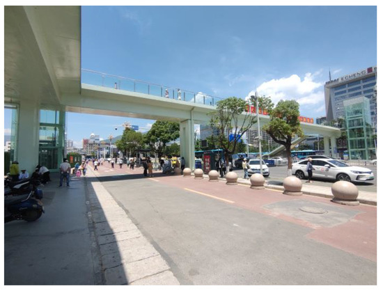
Figure 1.
Actual view of pedestrian bridge with hinged piers and columns.
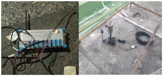
Figure 2.
Acceleration sensors and displacement sensors.
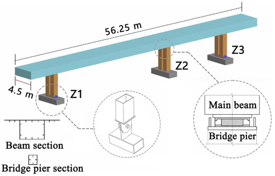
Figure 3.
The pedestrian bridge with steel box girder and hinged piers.
The dead load of the girder, which has been automatically calculated by the software, is 360 kN. Additionally, the dead load for Phase II, which includes the deck pavement and guard bar, is assumed to be uniformly distributed with a total value of 4.6 kN/m. The designed pedestrian load for the structure is 4.2 kN/m.
3. Pedestrian Load Models
Based on statistical findings [13], the continuous loading from pedestrian foot traffic can be represented by a Fourier series. This enables us to identify that the first- and second-order harmonic frequencies of the vertical loading fall within the range of 1.25–4.6 Hz, while the first-order harmonic frequencies of lateral loading are in the range of 0.5–1.2 Hz. If the fundamental frequency of the pedestrian bridges falls within these ranges, it can lead to resonant excitation and cause discomfort to the pedestrians.
Thus far, there have not been any cases of excessive vibrations in footbridges caused by second-order harmonic loads generated by pedestrians walking vertically [14]. Based on both domestic and international standards [15] and research results, there is only a need to take into account the first-order harmonic frequencies of the vertical loads. The German code (EN03) suggests for the frequency ranges for vertical and transverse comfort assessments to be between 1.25–3 Hz and 0.5–1.2 Hz, respectively.
Technical Specifications for Urban Pedestrian Overcrossing and Underpass (Draft for Comments) (CJJ/69-20XX) put forth a formula to calculate the vertical pedestrian vibration load excitation on footbridges. When analyzing the human-induced vibration comfort of pedestrian bridges, the Chinese code takes the same frequency range as EN03. It is advised that under no circumstances should the pedestrian density drop below 1.0 person/m2, and it should ideally not be lower than 1.5 person/m2. The code considers crowd density values of d = 0.2, 0.5, 1, 1.5, and 4.6 person/m2. When the density reaches 4.6 person/m2, the crowd is unable to move freely but takes small steps in place.
EN03-2007 is the most comprehensive code for crowd loading as it takes into account loading not only in the vertical direction but also in transverse directions. In this code, various load patterns are assigned based on the crowd density. Both of the above codes take the same equation for the harmonic loading of pedestrians in Equation (1). Thus, this paper follows the same expression as the following:
where is the pedestrian vibrating load per unit area is the harmonic load generated by a single passenger (N); P is the force component generated by a single passenger walking at a frequency of (N); represents the walking frequency, which is typically assumed to be equal to the fundamental frequency of the structure; n′ is the equivalent number of pedestrian flows on a loading area of ; is the reduction factor for the probability that the landing frequency is close to the fundamental frequency of the structure, which equals to 0.25 [4]; and is the damping ratio of the structure. When the loading area is , is the number of rows, When the direction of human-induced vibration is in the vertical direction, is taken as .
4. Bridge Dynamic Results
4.1. Numerical Simulation
A finite element model was developed by Midas Civil for the pedestrian bridge with hinged piers, as shown in Figure 4. The main girder and piers were modeled using beam elements. The model consists of 97 nodes and 88 elements. Based on the blueprint, the superstructure was intended to be rigidly connected to piers Z1 and Z3, with the bottom ends of the piers being transversely hinged. The translational degree of freedom for the main girder on top of pier Z2 was released, enabling it to slide freely in the longitudinal direction, while degrees of freedom for other directions were restrained. The box girder was constructed using Q355D steel, while all piers are composed of Q355D steel with rectangular cross-sections filled with C30 concrete. The modulus of elasticity for Q355D reinforcement was entered as 2.06 × 10¹¹ N/m2; Poisson’s ratio 0.31. The modulus of elasticity of C30 concrete was 3 × 101 (N/m2), Poisson’s ratio 0.2. The constant load and deck pavement load in the bridge were transformed into masses with the Z-direction. The analysis type of the time-range load condition is linear, and the analysis method used the direct integration method with a transient analysis. The analysis time was 50 s; the analysis time step was 0.01 s.
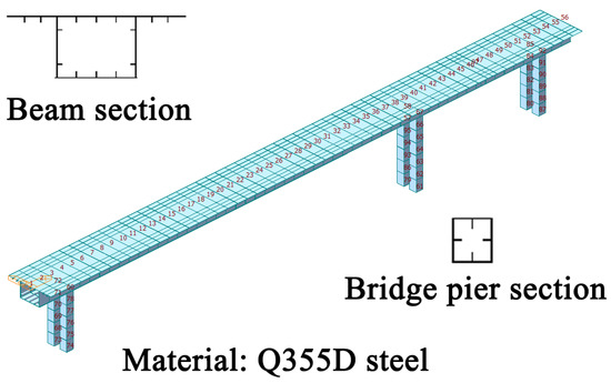
Figure 4.
Finite element model of the bridge.
Firstly, the modal analysis was conducted using the block Lanczos method to obtain the initial three modes of vertical vibration. As shown in Figure 5, the modal frequencies for the first three modes of vertical vibrations were found to be 3.92 Hz, 10.73 Hz, and 20.48 Hz for first-order symmetric, second-order antisymmetric, and third-order antisymmetric vertical bending, respectively. It is worth noting that these values are in proximity to the frequencies captured during testing of the completed bridge structure (see Section 4.2). The load model for pedestrians, discussed in Section 2, was implemented to compute the maximum mid-span acceleration of the main girder at varying unit loads of d = 0.2, 0.5, 1, 1.5, and 4.6 person/m2. These unit loads corresponded to the number of pedestrians loaded at the mid-span position. The acceleration time history outcomes are depicted in Figure 4.

Figure 5.
First three orders of modes. (a) First-order symmetric mode; (b) second-order antisymmetric mode; and (c) third-order antisymmetric vertical bending mode.
It can be seen that the peak accelerations at the mid-span were calculated as 0.335, 0.566, 2.175, 2.664, and 4.666 m/s² for d = 0.2, 0.5, 1, 1.5, and 4.6 person/m2, respectively.
4.2. Experimental Testing
To evaluate the dynamic properties of the structure, five measurement points were placed along the longitudinal axis of the bridge deck, as demonstrated in Figure 5. Donghua 2D001 sensors were installed and dynamic signal acquisition was carried out using the Donghua DH5902N testing system. The experiment was conducted under zero-load conditions. The natural frequencies of vibration were determined through a spectral analysis to be 3.906 Hz, 11.719 Hz, and 19.238 Hz, respectively, for the first, second, and third modes.
Furthermore, a series of 10 walking excitation load cases were established, consisting of scenarios with one to five individuals walking and jumping. A single person walking advanced at an average speed along the axis of the deck. In the case of multiple individuals loading the bridge deck, they moved about randomly across its surface. Their moving direction was set as Z1 to Z3. To some extent, the maximum structural acceleration response exhibits a linear relationship with the rate of pedestrian synchronization [16]; for the in situ test, however, it was hard to control it. Thus, the experimenters randomly stepped in the multi-person condition. The unit load corresponding to the number of pedestrians is loaded at the mid-span position and time course analysis is performed, and the results are shown in Figure 6. The acceleration time history curves are shown in Figure 7, and the maximum values of acceleration are summarized in Table 1. The acceleration time curves of the main beam structure under each working condition are shown in Figure 8 and Figure 9.
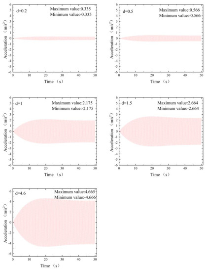
Figure 6.
Acceleration time histories at mid−span.
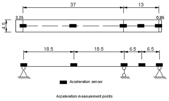
Figure 7.
Acceleration measurement point.

Table 1.
Peak acceleration of different loading cases.
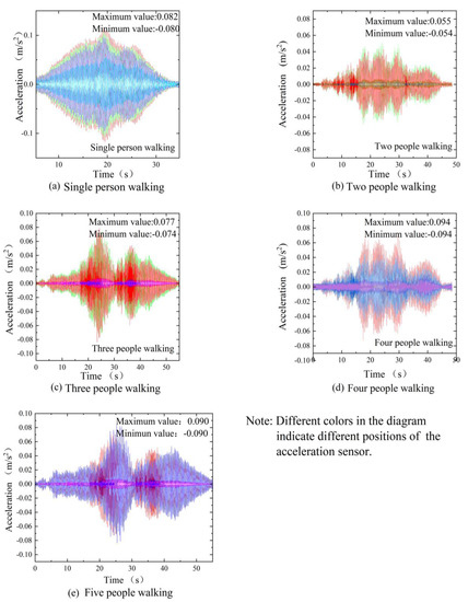
Figure 8.
Acceleration time history curve of 1–5−person walking on the deck.
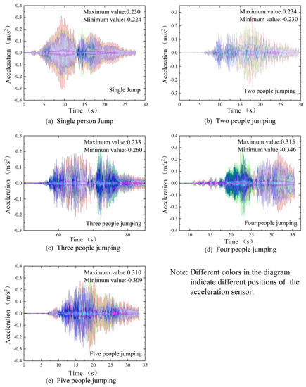
Figure 9.
Acceleration time history curve of 1–5−person jumping.
4.3. FRF Method Evaluation
The FRF (frequency response function) method for rapid evaluation of the resonant response of pedestrian bridges is provided in AISC Design Guide 11. The amplitude of the frequency response function (FRF) can be determined through a harmonic response analysis with a unit load applied at the peak point of the modal shape. The influence of pedestrian paths on the bridge deck is considered and a resonance accumulation factor is introduced. The resonant acceleration between the pedestrian and the bridge, as calculated by the FRF method, is equal to the product of the maximum frequency response function FRFmax, dynamic load factor α, pedestrian body mass G, and resonance accumulation factor ρ,
where is the maximum peak frequency response function in the range of 0 to 9 Hz from the harmonic response analysis, is the structural damping ratio, is the structural fundamental frequency (Hz), and is the sweep frequency rate (Hz).
When invoking the harmonic response analysis module for a frequency sweep, a unit load equal to the number of pedestrians on the bridge is applied at the peak point of the first-order vibration mode of the structure. Since the harmonic response analysis can only extract the maximum displacement S in the span, and the index of comfort is the peak acceleration, it is necessary to convert S into the peak frequency response function with Equation (7), and then using Equation (2) to calculate the peak acceleration .
The peak acceleration when d = 0.2 person/m2, calculated by the FRF method for the hinged piers and pedestrian bridge tested in this study, was 0.382 m/s2.
4.4. Generalized SDOF Procedure
Based on the fundamental principles of structural dynamics, every mode of the structure can be illustrated with a corresponding Single Degree of Freedom (SDOF) system. This approach is applied to estimate the acceleration response induced by dynamic loads. The dynamic characteristics of the structure can be computed with a modal analysis of the finite element model, where the arbitrary vibrations of the structure can be described with a linear combination of several harmonic vibrations in the range of the intrinsic frequencies of the structure. Thus, the structure can be transformed into several vibrating systems of different equivalent masses, each of which is a single degree of freedom. Each equivalent SDOF system has an intrinsic frequency and mass equal to the intrinsic frequency and corresponding modal mass at each mode shape, respectively. The maximum acceleration of an SDOF system at resonance, , can be expressed as the following:
where is the modal-generalized walking load amplitude , calculated according to Equation (9); is the generalized mass calculated for the same vibration type in the unit of kg, calculated with Equation (10); is the damping ratio of the mode; and is the logarithmic decay rate of modal damping,
where is the sidewalk width; is the modal displacement (; is the pedestrian harmonic load; and
where is the line mass of the main beam of the pedestrian bridge .
The peak acceleration of the structure when d = 0.2 person/m2, calculated using the conventional SDOF method, is 0.293 m/s².
4.5. Improved Calculation of SDOF Procedure
The equations of motion for a single-degree-of-freedom system, under external loading, can be easily obtained [1]. Due to the effect of damping, the transient response of the free vibration will decay away quickly, leaving only the steady state response, and the solution of the vibration response can be directly simplified as the following:
The acceleration can be obtained as
and the peak acceleration is
When the structural system exhibits resonance, the crowd load function can be expressed as follows:
where is the power factor; is the weight of the excitation, which is given in AISC#11 as ; and
Since the position of the force changes during walking, the exciter and receptor will not appear at the displacement amplitude of the vibration mode at the same time. Therefore, it is reasonable to introduce a reduction factor R. In this case, the peak acceleration can be expressed as follows:
For the general girder bridge structure, can be taken as 0.7 [12] and is the mass reduction factor, which we take as 0.5. Substituting into Equation (15), the following can be obtained:
where , and .
For the resonance case, can be expressed as follows:
The peak acceleration when d = 0.2 person/m2, calculated using the modified SDOF method, is 0.315 m/s².
The above derivation shows that when using the improved SDOF method, only the modal frequency and modal mass of the bridge under testing need to be calculated to derive the peak acceleration. When applied to the actual test, this can avoid the effect of inconsistent crowd loading, and can omit the process of a static test to obtain the bridge deflection in the original generalized SDOF system. This improves the experimental accuracy and saves considerable cost.
Improved SDOF Method Validation
In addition to the above-mentioned articulated pier and column pedestrian bridges, the applicability and accuracy of the improved SDOF method were verified by calculating the peak accelerations of three pedestrian bridges in use, drawing on the study by Cui et al. [17] on cantilevered large-span passable pedestrian bridges.
- (1)
- The deck of a pedestrian bridge in Wuhan [18] is made of steel box girders with three spans, with a main span of 45 m and a deck width of 7 m. The whole bridge adopts eight harp-type ties. The first-order vertical vibration is 2.058 Hz, the damping ratio is 0.5%, and the vibration mass is about 48,733.42 kg. The observed pedestrian density on the steel bridge deck is about 0.2 person/m². The measured peak acceleration in the span is 1.43 m/s², and the improved SDOF method calculates it as 1.62 m/s², creating an error of 13.28%.
- (2)
- A pedestrian steel bridge in Podgorica, Montenegro [19] has a total length of 104 m, a main span of 78 m, and a width of 3 m. The first-order vertical vibration is 2.04 Hz, the damping ratio is 0.26%, and the vibration mass is about 58,000 kg. During two days of field observation, there were up to 80 pedestrians on the steel bridge; about 0.2 person/m² was exerted close to the sinusoidal half-wave excitation. The measured peak span acceleration was 2.92 m/s², and the improved SDOF method calculated the peak span acceleration as 2.64 m/s², creating an error of 10.60%.
- (3)
- A steel pedestrian bridge in the Beijing North Third Ring [20] has a total length of 104 m and a main span of 70.7 m. The first-order vertical vibration is 2.4 Hz, the damping ratio is 1%, the vibration mass is about 47,490 kg, and d = 0.2 person/m². The measured peak acceleration in the span is 0.71 m/s², and the improved SDOF method calculates it as 0.74 m/s², creating an error of 4.22%.
All three bridges mentioned above are steel pedestrian bridges, but they have different spans, first-order vertical vibration patterns, and damping ratios. With the same crowd density, the peak acceleration in the span calculated by the improved single-degree-of-freedom method has an error range of 4.22% to 13.28% compared with the results obtained from the experimental measurements. The accuracy of the improved single-degree-of-freedom method proposed in this study for calculating the maximum peak acceleration in the span when the pedestrian resonates with the pedestrian bridge is initially verified.
5. Comfort Evaluation
The German pedestrian bridge design guidelines EN03 include research results since 2000, covering the avoidance of sensitive frequency method and the limitation of dynamic response method, showing obvious superiority over other codes. EN03 also takes into account different pedestrian densities and vibration perception expectations, and comfort levels are grouped according to pedestrian densities. The Chinese Technical Specification for Urban Footbridges and Pedestrian Walkways (Draft for Comments) (CJJ/69-20XX) also considers the above aspects, so both code specifications were used in this study for evaluation. The comparison of test and evaluation results in this paper is shown in Table 2.

Table 2.
Acceleration peak comparison and comfort evaluation.
It can be seen that the evaluation results using Chinese and German codes are close to each other. Although the bridges satisfy the requirement of vertical frequency (greater than 3 Hz), the comfort level becomes poor when d ≥ 1, which is the case of daily commuting traffic. Thus, this bridge needs further improvement to ensure pedestrian comfort.
With the same excitation frequency, the improved SDOF system test method exhibits only 9.84% error compared to the real measurement and provides consistent comfort evaluation. Compared to the numerical simulation method, the error is merely 6.35%, with a consistent comfort evaluation. In comparison to the FRF method, the error is a mere 10.40%, and the comfort evaluation is also consistent. When compared to the generalized SDOF method, the error is 18.09%, and the comfort evaluation is still consistent. As a result, the improved SDOF method not only produces more precise results but is also more accurate than the generalized SDOF method when assessing comfort consistently. The improved SDOF system test method is appropriate for pedestrian bridges with a crowd density of d ≤ 0.2 person/m2. This method only requires modal testing to establish the peak acceleration, allowing practical calculation of peak span acceleration and saving time when compared to actual testing. Standardizing the selection of a representative testing population for pedestrian bridges is difficult, and the human and crowd load excitation conditions cannot be standardized. Therefore, the improved SDOF system test method is a proven approach for evaluating pedestrian bridge comfort.
6. Conclusions
To evaluate the dynamic response and comfort of pedestrian bridges featuring steel structures with hinged piers, an improved SDOF method was proposed. The study involved comparing findings from numerical simulations with in situ measurements. The following conclusions can be drawn from the study:
- (1)
- Improved testing methods for single-degree-of-freedom systems, where only modal testing is required to derive peak acceleration. Errors caused by different testers are eliminated. Errors due to deflection measurements are eliminated compared to the generalized single-degree-of-freedom system. It is applicable for pedestrian bridges with a crowd density of d ≤ 0.2, the peak acceleration in the span of the measured pedestrian bridge can be calculated quickly, and the error range is controlled between 4.22% and 13.28% with the verification of the measured bridges.
- (2)
- Compared with the actual test, the improved SDOF method in this paper saves considerable time cost and economic cost because it does not require a human-induced excitation test. The speed of pedestrian bridge comfort evaluation has been improved.
- (3)
- Although the bridges analyzed in this paper satisfy the requirement of having a first-order vertical frequency greater than 3 Hz, the acceleration exceeds the comfort zone according to the EN03 when the crowd density is d ≥ 1 person/m2 for daily commuting. Thus, this bridge requires further improvement to guarantee pedestrian comfort. It is therefore recommended to retrofit the bridge with Tuned Mass Damper (TMD) vibration damping measures.
Author Contributions
Conceptualization, S.Y. and J.Y.; methodology, S.Y.; software, S.Y.; validation, S.Y., J.Y. and R.L.; formal analysis, S.Y.; investigation, S.Y.; resources, S.Y.; data curation, S.Y.; writing—original draft preparation, S.Y.; writing—review and editing, S.Y.; visualization, S.Y.; supervision, S.Y.; project administration, S.Y. All authors have read and agreed to the published version of the manuscript.
Funding
This research received no external funding.
Institutional Review Board Statement
Not applicable.
Informed Consent Statement
Not applicable.
Data Availability Statement
First published.
Acknowledgments
We would like to express our gratitude to the anonymous reviewers for their time and efforts devoted to improving the quality of this research. The detailed and valuable comments that we obtained from them are very appreciated. We thank LetPub (www.letpub.com, accessed on 30 March 2023) for linguistic assistance and pre-submission expert review.
Conflicts of Interest
The authors declare no conflict of interest.
References
- Beijing Municipal Engineering Design & Research Institute. Technical Specifications for Urban Pedestrian Overcrossing and Underpass CJJ 69-95, 1st ed.; China Architecture & Building Press: Beijing, China, 1996; pp. 1–32. [Google Scholar]
- Heinemeyer, C.; Butz, C.; Keil, A.; Schlaich, M.; Goldack, A.; Trometer, S.; Lukić, M.; Chabrolin, B.; Lemaire, A.; Martin, P.-O.; et al. Design of Lightweight Footbridges for Human Induced Vibrations, 1st ed.; European Communities: Luxembourg, 2009; pp. 1–82. [Google Scholar]
- British Standards Institution. Steel, Concrete, and Composite Bridges, 1st ed.; British Standards Institution: London, UK, 1978. [Google Scholar]
- Research Found for Coal and Steel. Design of Footbridges Guideline; Research Found for Coal and Steel: Aachen, Germany, 2008; pp. 1–31. [Google Scholar]
- Dallard, P.; Fitzpatrick, T.; Flint, A.; Low, A.; Smith, R.R.; Willford, M.; Roche, M. London millennium bridge: Pedestrian-induced lateral vibration. J. Bridge Eng. 2001, 6, 412–417. [Google Scholar] [CrossRef]
- Li, H.L.; Chen, Z.Q. A calculation method for footbridge vibration under stochastic pedestrian loading. J. Hunan Univ. (Nat. Sci.) 2013, 40, 22–31. [Google Scholar]
- Xie, X.; Zhong, J.R.; Zhang, H.; Zhang, Z.C. Calculation method for vertical human-bridge dynamic interaction. J. Vib. Shock 2016, 35, 108–114. [Google Scholar] [CrossRef]
- Cao, L.L.; Cao, D.; Zhang, Z.Q.; Li, A.Q. Dynamic characteristic parameter and acceleration response of footbridge under random crowd walking. J. Southeast Univ. Nat. Sci. Ed. 2018, 48, 1028–1035. [Google Scholar] [CrossRef]
- Van Nimmen, K.; Lombaert, G.; De Roeck, G.; Van den Broeck, P. Vibration serviceability of footbridges: Evaluation of the current codes of practice. Eng. Struct. 2014, 59, 448–461. [Google Scholar] [CrossRef]
- Živanović, S.; Pavić, A.; Ingólfsson, E.T. Modeling spatially unrestricted pedestrian traffic on footbridges. J. Struct. Eng. 2010, 136, 1296–1308. [Google Scholar] [CrossRef]
- Zhu, Q.K.; Meng, W.C.; Zhang, Q.; Ma, Q.F. High-efficiency evaluation of human-induced vibration serviceability of footbridge. J. Vib. Meas. Diagn. 2022, 42, 945–951. [Google Scholar] [CrossRef]
- Murray, T.M.; Allen, D.E.; Ungar, E.E. Floor Vibrations Due to Human Activity; American Institute of Steel Construction: Chicago, IL, USA, 2017. [Google Scholar]
- Zhu, Q.K.; Li, H.N.; Du, Y.F.; Zhang, Q. Quantitative evaluation of vibration serviceability of pedestrian brigde under different walking speed. Eng. Mech. 2016, 33, 97–104. [Google Scholar] [CrossRef]
- Qu, H.L. Research on Human-Induced Vibration and Comfort Evaluation of Pedestrian Bridges. Master’s Thesis, Beijing Municipal Engineering Research Institute, Beijing, China, 2014. [Google Scholar]
- Chen, J.; Peng, X.Y.; Wang, L. Modeling of three-way unipedal drop-step load curve test based on gait analysis technique. China Civ. Eng. J. 2014, 47, 79–87. [Google Scholar] [CrossRef]
- Ke, L.; Wang, D.L.; Chen, A.R. Research on human-induced vibration of long-span cable-supported footbridge in scenic spot. J. Highw. Transp. Res. Dev. (Chin. Ed.) 2013, 30, 101–105. [Google Scholar] [CrossRef]
- Cui, C.; Ma, R.; Hu, X.; He, W. Vibration Analysis for Pendent Pedestrian Path of a Long-Span Extradosed Bridge. Sustainability 2019, 11, 4664. [Google Scholar] [CrossRef]
- Cai, H.; He, W.; Chen, L.L.; Xie, W.P. Dynamic characteristics testing and vibration serviceability analysis on footbridges. J. Wuhan Univ. Technol. (Transp. Sci. Eng.) 2013, 37, 362–365, 368. [Google Scholar] [CrossRef]
- Brownjohn, J.; Zivanovic, S.; Pavic, A. Crowd dynamic loading on footbridges. In Proceedings of the Third International Conference on Footbridges, Porto, Portugal, 2–4 July 2008. [Google Scholar]
- Li, Q. Stochastic Vibration and Optimal Control of Large Span Pedestrian Bridge and Building Cover under Human-Induced Excitation; Tsinghua University: Beijing, China, 2010. [Google Scholar]
Disclaimer/Publisher’s Note: The statements, opinions and data contained in all publications are solely those of the individual author(s) and contributor(s) and not of MDPI and/or the editor(s). MDPI and/or the editor(s) disclaim responsibility for any injury to people or property resulting from any ideas, methods, instructions or products referred to in the content. |
© 2023 by the authors. Licensee MDPI, Basel, Switzerland. This article is an open access article distributed under the terms and conditions of the Creative Commons Attribution (CC BY) license (https://creativecommons.org/licenses/by/4.0/).