Article

An AC-DC LED Integrated Streetlight Driver with Power Factor Correction and Soft-Switching Functions

Department of Electrical Engineering, I-Shou University, Kaohsiung City 84001, Taiwan
*
Author to whom correspondence should be addressed.
Sustainability 2023, 15(13), 10579; https://doi.org/10.3390/su151310579
Submission received: 20 April 2023 / Revised: 26 June 2023 / Accepted: 3 July 2023 / Published: 5 July 2023
(This article belongs to the Special Issue Sustainable Energy Systems and Renewable Generation)

Abstract

:
The use of light-emitting diodes (LEDs) in street lighting applications has been greatly welcomed with the current trends of energy saving, environmental protection, carbon reduction, and sustainable development. This paper presents a novel AC-DC LED integrated streetlight driver that combines an interleaved buck converter with a coupled inductor and a half-bridge series resonant converter with a full-bridge rectifier into a single-stage power conversion topology with power factor correction (PFC) and soft switching capabilities. The PFC is achieved by designing the coupling inductor in the interleaved buck converter sub-circuit in discontinuous conduction mode. In addition, the resonant tank in the half-bridge series resonant converter sub-circuit is designed to be similar to an inductive load, thus giving the power switch a zero-voltage switching (ZVS) function, decreasing switching losses and increasing the overall efficiency of the proposed circuit. A prototype circuit of the proposed LED integrated streetlight driver with a power rating of 165 W (235 V/0.7 A) and 110 V input utility voltage has been developed and tested. According to the measurement results, a power factor greater than 0.98, a total harmonic distortion coefficient of the input current less than 3%, and an efficiency greater than 89% were obtained in the AC-DC LED integrated streetlight driver. Therefore, the experimental results are satisfactory and demonstrate the functionality of the proposed AC-DC LED integrated streetlight driver.

1. Introduction

Proper street lighting is important for road safety by improving visibility, making navigation easier, keeping road users and pedestrians safe, and reducing crime. Therefore, a convenient street lighting system will facilitate the use of roads by drivers and pedestrians [1,2]. The light source used in traditional street lighting is a high-pressure mercury lamp, and it is a kind of gas discharge lamp. A high-pressure mercury lamp contains mercury vapor inside, which produces bright light in the form of gas discharge, and its advantages are high luminous efficiency and a long service life. Due to the mercury contained in the lamp tube, there will be environmental pollution problems when the lamp tube is aged and discarded. In addition, high-pressure mercury streetlamps are a kind of lamp with high energy consumption, serious light decay and a lack of environmentally friendly features. Under the current trend of environmental protection, energy savings, carbon reduction and sustainable development, the use of high-pressure mercury lamps for streetlight applications has been greatly reduced.
Streetlights play a very important role in modern life and are an important infrastructure for social security and road safety. Street lighting is a high energy-consuming facility that requires long-term lighting, which is a burden to environmental protection, electricity consumption and government finance. In line with the global trend of clean energy, energy saving and carbon reduction, as well as reducing the financial burden of the government, street lighting, as an important type of urban lighting, can meet the demand of environmental protection by using energy-saving and efficient light sources [3,4,5,6]. Advantages of light-emitting diodes (LEDs) over high-pressure mercury lamps are their long life, high energy efficiency, low installation and maintenance costs, and the absence of toxic chemicals such as mercury, which contributes to environmental protection and sustainable development. Therefore, from the perspective of environmental protection and economy, LED lighting technology has significant advantages in the streetlamp market. In addition, LED streetlights offer other benefits, including improved nighttime visibility through improved color rendering, color temperature and brightness uniformity. Moreover, LED streetlights can be turned on quickly because they do not require preheating time and do not produce ultra-violet (UV) light, which attracts bugs. To summarize, several advantages of using LED streetlights over traditional lighting technologies include energy efficiency, long life span, improved lighting quality, environmental friendliness, and instant starting. First, LED streetlights have high energy efficiency, compared with traditional street lights; energy consumption can be reduced by 50%, thus, greatly saving energy costs. Second, compared to traditional lighting technologies, LED streetlights have a longer life span, which reduces maintenance costs and the need for frequent replacement. Third, compared with traditional lighting technology, LED streetlights have better lighting quality, higher color rendering index (CRI), and better uniformity of light distribution. Fourth, LED streetlights do not contain harmful substances such as mercury or lead, so they are friendly to the environment and easier to dispose of aging lamps. Finally, in contrast to traditional lighting technology, LED streetlights have an instant start time, which means they can be switched on and off as required without pre-heating time. As a result, LEDs provide a more cost-effective, environmentally friendly, and efficient option with attractive properties and play an important role in replacing traditional streetlights [7,8,9,10,11,12,13,14,15,16,17,18,19,20,21,22].
Power factor is defined as the ratio between active power and apparent power and is an important electrical parameter that measures the efficiency of converting electrical energy into useful power output. Typically, electrical equipment powered by an AC power source requires a power factor measurement. Power factor correction (PFC) is important and necessary in order to restore the power factor to as close to unity as possible and thus achieve energy savings. The advantage that can be achieved by correcting the power factor is the environmental benefit. By improving the power factor, it is possible to reduce electricity consumption, which means reducing greenhouse gas emissions and the consumption of fossil fuels in power stations, thus improving energy efficiency. The International Electrotechnical Commission (IEC) provides an international standard such as IEC 61000-3-2 Electromagnetic Compatibility (EMC)—Part 3-2: Limits—including harmonic current emission limits for single-phase power supply equipment with input currents equal to or less than 16 A, and through this standard specifies the maximum values from the second harmonic up to and including the 40th harmonic current to limit supply voltage distortion. The purpose of the IEC 61000-3-2 international standard is to limit the harmonic currents generated by electrical equipment in order to maintain the mains voltage quality. Passive PFC circuits are the simplest way to control harmonic currents by using filters, which consist of capacitors or inductors that make a nonlinear device appear more like a linear load and which can only tolerate the passage of low frequency current components (mains frequency 60 Hz or 50 Hz) [23]. Switched-mode power supplies (SMPS) are electronic power supplies that incorporate switching regulators to efficiently convert electrical power. SMPS are smaller and lighter than linear power supplies, making them ideal for use in portable devices and space-constrained applications. In addition, SMPS are highly efficient, typically above 80%, which means that they waste less energy in the form of heat, making them ideal for applications where energy efficiency is important. In addition, SMPS are typically less expensive to manufacture than linear power supplies, making them a cost-effective solution for many applications. Typically, an SMPS can achieve a power factor of about 0.7–0.75 using passive PFC, while the SMPS without any power factor correction has a power factor of only 0.55–0.65. In practical applications, passive PFC circuits are often ineffective in improving power factor, and another disadvantage is that passive PFC circuits require larger inductors or capacitors than active PFC circuits of equal power. Therefore, an active PFC circuit is an advantageous way to achieve input mains current shaping. It uses power electronics to modify the waveform of the load current to improve and obtain a power factor of up to 0.99 [24].
Hard switching is a switching technique used in power electronics, where the power switch is turned on and off at a high frequency, typically several kilohertz to several megahertz. During the switching process, there is a brief period where the switch is in a transition state, during which the voltage and current across the switch are not zero. This results in high switching losses and power dissipation in the switch. In hard switching, the power switch is turned on and off abruptly, and the energy stored in the parasitic capacitances and inductances of the switch and the surrounding circuitry is dissipated as heat. This can lead to increased power consumption, reduced efficiency, and decreased reliability of the system. The advantage of soft switching technology over hard switching of power switches in SMPS or power converters is that one or more power switches have zero voltage switching (ZVS) or zero current switching (ZCS) during the power switch on or off transition, which greatly reduces switching losses. The LED driver circuit is an SMPS that converts power from AC mains to DC for supplying LED loads. Therefore, it is recommended that LED driver circuits for street lighting applications use active PFC to regulate the utility line current and that soft switching techniques be employed on power switches to reduce switching losses.
Figure 1 shows the block diagram of the conventional two-stage LED streetlight driver with PFC with soft-switching characteristic, which consists of a power factor corrector as the first stage circuit and a DC-DC converter as the second stage circuit to provide the rated voltage and current to the LED streetlight module; each level of circuit needs its own controller [25,26,27,28,29,30]. Reference [25] describes a two-stage LED driver circuit that consists of a boost converter with PFC as the first stage circuit and a half-bridge LLC resonant converter with soft-switching characteristics as the second stage circuit. Reference [26] had proposed a two-stage LED driver circuit in which the first stage is a boost converter with PFC and the second stage is an asymmetrical half-bridge converter with a soft-switching function for street lighting applications. Reference [27] had presented a two-stage quasi-resonant LED driver with a digital control method, and the first stage of the presented converter is a boost circuit with a PFC function, and the second stage is a dual-buck circuit that works in a quasi-resonant zero voltage switching state. The output of the presented converter is a square wave that drives two branches of antiparallel LEDs. Because of the soft-switching characteristics of the presented converter, switching losses are reduced and efficiency is significantly improved. Due to the simple structure of the dual-buck circuit topology, this converter reduces the volume and cost compared with other two-stage LED drivers. Reference [28] describes a two-stage high power factor LED driver without optocoupler, whose first stage is an isolated PFC converter without optocoupler, and whose second stage is a non-isolated DC/DC LED driver with constant current control. The optocoupler and secondary amplifier circuits of the first PFC stage can be removed. On the other hand, the output capacitance of the PFC stage can be reduced due to the low output ripple voltage requirement of the second stage of the two-stage LED driver and the acceptably wide input voltage range. Therefore, the circuit structure of the proposed optocoupler-free two-stage high power factor LED driver is greatly simplified. Reference [29] proposed a two-stage driver with PFC and dimmability, which has a PFC boost converter in the first stage and a three-channel floating buck circuit topology in the second stage for providing accurate color control and high color rendering index (CRI) for high-efficiency light-emitting diode (LED) luminaires using three strings of high-voltage rated LEDs. Reference [30] has described the control technique for a high power density electrolytic-capacitor-free offline LED driver that utilizes a merged energy buffer for twice-line-frequency energy buffering. The LED driver consists of two stages: a four-switch buck-boost PFC stage and an LLC resonant DC-DC stage. The control technique proposed for the PFC stage utilizes a new mode splitter to ensure buck to boost and vice versa mode transitions. A feedforward control strategy is proposed for the DC-DC stage, combined with feedback control, to ensure that the output voltage is well regulated by mitigating undesirable spikes in the output voltage.
Figure 2 shows the block diagram of an integrated LED streetlight driver with PFC with soft-switching characteristic, which combines a power factor corrector and a DC-DC converter into a single-stage power conversion to supply an LED streetlight module, and only one controller for the integrated power converter is required. A number of previously developed and implemented integrated LED streetlight drivers combine a first-stage power factor corrector and a second-stage DC-DC converter into a single-stage topology, which reduces the number of circuit components and improves overall conversion efficiency [31,32,33,34,35]. In order to reduce the number of power switches and improve the overall circuit efficiency of the conventional two-stage version, this paper proposes a new AC-DC LED integrated streetlight driver with PFC and soft switching functions. The description and analysis of the operation mode are demonstrated, as well as experimental results obtained from a prototype circuit of the proposed LED streetlight driver.

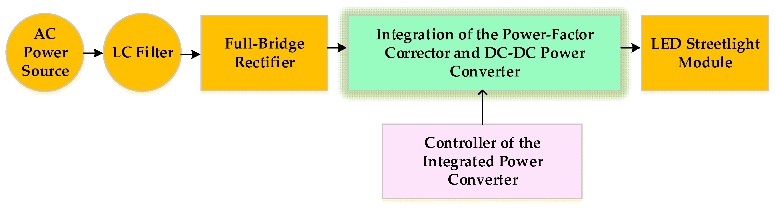
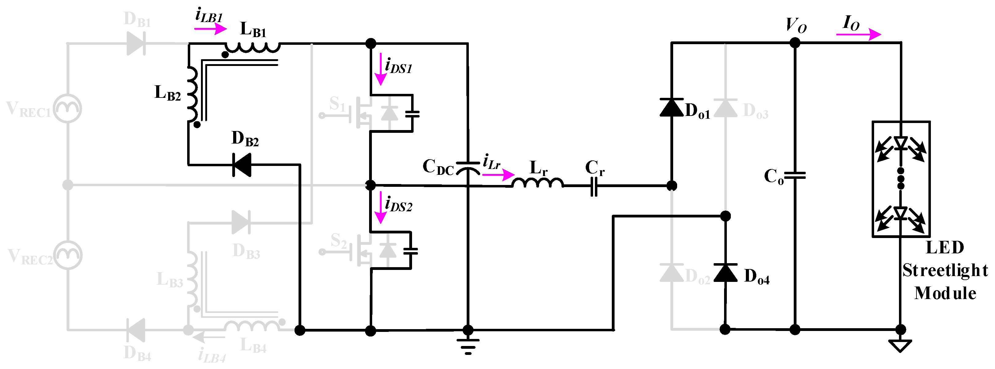
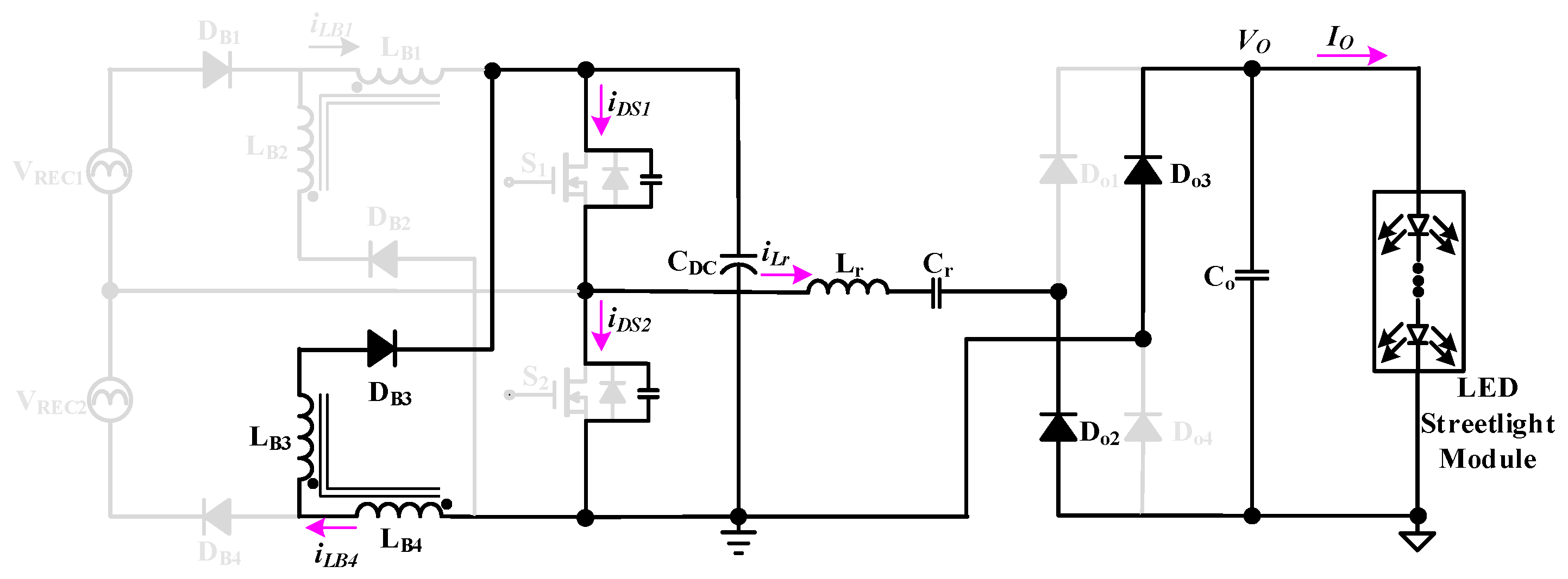
2. Description and Analysis of Operational Modes in the Proposed AC-DC LED Integrated Streetlight Driver

Figure 3 shows the proposed AC-DC LED integrated streetlight driver that combines an interleaved buck converter with a coupled inductor and a half-bridge series resonant converter with a full-bridge rectifier to power the LED streetlight module. The interleaved buck converting sub-circuit is made up of two capacitors (Cin1 and Cin2), two coupled inductors (LB1 and LB2; LB3 and LB4), four diodes (DB1, DB2, DB3, and DB4), two power switches (S1 and S2), and a DC-linked capacitor (CDC). The half-bridge series resonant converter with a full-bridge rectifier sub-circuit contains a DC-linked capacitor (CDC), two switches (S1 and S2), a resonant inductor (Lr), a resonant capacitor (Cr), four diodes (Do1, Do2, Do3 and Do4), and a capacitor (Co) with the LED streetlight module. In addition, the coupled inductors (LB1 and LB2; LB3 and LB4) are designed to operate in discontinuous conduction mode (DCM) in order to carry out input utility line current shaping naturally without the use of a PFC controller [34].
Figure 4 shows the equivalent circuit of the proposed single-stage LED streetlight driver when analyzing and illustrating the operating modes. In order to analyze and illustrate the operational modes of the proposed LED streetlight driver, the following assumptions were made.
(a)
Since the switching frequencies of the two power switches S1 and S2 are much higher than the frequency of the utility line input voltage vAC, the sinusoidal utility line input voltage vAC can be considered as a constant value during each high frequency switching cycle.
(b)
VREC1 and VREC2 represent the input voltage sources of the input capacitors Cin1 and Cin2 after full-bridge rectification, respectively.
(c)
The power switches S1 and S2 operate in a complementary state, and the duty cycle of the two switches is about 0.5, taking into account the intrinsic diode and parasitic capacitance of the power switches.
(d)
Disregard the on-state voltage drop and its equivalent resistance for all diodes.
(e)
Design the LC series resonant tank circuit to operate on inductive load.
(f)
Design coupled inductors LB1, LB2, LB3 and LB4 to operate in discontinuous conduction mode.
(g)
The remaining circuit elements are considered ideal.
The operating modes of the presented LED streetlight driver are shown in Figure 5, Figure 6, Figure 7, Figure 8, Figure 9, and Figure 10, respectively. Figure 11 shows the key waveforms of the proposed LED streetlight driver. The utility line input voltage vAC can be expressed as:
v A C ( t ) = 2 v A C - r m s sin 2 π f A C t
where vAC-rms is the root-mean-square (rms) value of the utility line input voltage, and fAC is the frequency of the utility line input voltage.
Representing the input voltage sources VREC1 and VREC2 on the input capacitors Cin1 and Cin2 after full-bridge rectification can be expressed as:
V R E C 1 ( t ) = V R E C 2 ( t ) = 2 v A C - r m s sin 2 π f A C t 2
The analysis of the operation in the proposed LED streetlight driver is described in detail below.
Operation Mode 1 (t0t < t1): Figure 5 shows the equivalent circuit of operational mode 1 in the proposed LED integrated streetlight driver. The power switch S1 is driven to conduct. The voltage source VREC1 provides energy to the coupled inductor LB1 through the diode DB1 and the power switch S1, and the inductor current iLB1(t) increases linearly, which can be expressed as follows:
i L B 1 ( t ) = 2 v A C - r m s sin ( 2 π f A C t ) 2 L B 1 t t 0
The DC link capacitor CDC provides energy to the parasitic capacitance of the power switch S2 via the power switch S1. At the same time, the DC link capacitor CDC provides energy to the resonant inductor Lr, the resonant capacitor Cr, the output capacitor Co, and the LED streetlight module via the power switch S1 and the diodes Do1 and Do4. When the power switch S1 is turned off, the inductor current iLB1 rises to the maximum value, and this operational mode ends. The maximum value iLB1-max of the inductor current iLB1 can be expressed as:
i L B 1 - max = 2 v A C - r m s sin ( 2 π f A C t ) 2 L B 1 f S d u t y
where fS and duty are the switching frequency and duty ratio of the power switch gate-driving signal working at high frequency, respectively.
Operational Mode 2 (t1t < t2): Figure 6 shows the equivalent circuit of operational mode 2 in the proposed LED integrated streetlight driver. After the switch S1 is turned off, due to the polarity change of the voltage on the coupled inductors LB1 and LB2, the diode DB2 presents a forward bias and is turned on. The coupled inductors LB1 and LB2 provide energy to the DC link capacitor CDC via DB2, and the inductor current iLB1(t) decreases linearly, which can be expressed as follows:
i L B 1 ( t ) = 2 v A C - r m s sin ( 2 π f A C t ) 4 L B 1 t t 1
The DC link capacitor CDC, the parasitic capacitor of the power switch S2, and the resonant inductance Lr provide energy to the parasitic capacitor of the power switch S1, the resonant capacitor Cr, the output capacitor Co, and the LED streetlight module through the diodes Do1 and Do4. When the energy of the parasitic capacitance of the power switch S2 is completely released, the voltage VDS2 of the power switch S2 drops to zero, the intrinsic diode of the power switch S2 is turned on, and this operational mode ends.
Operational Mode 3 (t2t < t3): Figure 7 shows the equivalent circuit of operational mode 3 in the proposed LED integrated streetlight driver. In the previous operation mode, the parasitic capacitance energy of the power switch S2 is released completely, the voltage VDS2 of the power switch S2 drops to zero, and the intrinsic diode of the power switch S2 is turned on. This mode starts when S2 is driven on and has zero voltage switching characteristics. The voltage source VREC2 provides energy to the coupled inductor LB4 through the diode DB4 and the power switch S2. The inductor current iLB4(t) increases linearly, which can be expressed as follows:
i L B 4 ( t ) = 2 v A C - r m s sin ( 2 π f A C t ) 2 L B 4 ( t t 2 )
The voltage of the parasitic capacitor of S1 is equal to the voltage VDC of the DC link capacitor CDC. The coupled inductors LB1 and LB2 provide energy to the DC link capacitor CDC via the diode DB2. The inductor current iLB1 continues to show a linear decrease, which can be expressed as follows:
i L B 1 ( t ) = 2 v A C - r m s sin ( 2 π f A C t ) 4 L B 1 t t 2
The resonant inductor Lr provides energy to the resonant capacitor Cr, the output capacitor Co and the LED streetlight module through the essential diode of the power switch S2 and the diodes Do1 and Do4. When the inductor current iLB1 drops to zero, this operational mode ends.
Operational Mode 4 (t3t < t4): Figure 8 shows the equivalent circuit of operational mode 4 in the proposed LED integrated streetlight driver. This mode starts when the inductor current iLB1 drops to zero and the power switch S2 is driven to conduct. The DC link capacitor CDC provides energy to the parasitic capacitance of the power switch S1 via the power switch S2. The capacitor Cr provides energy to the inductor Lr, the capacitor Co and the LED streetlight module via the diodes Do2 and Do3 and the power switch S2. When the power switch S2 is turned off, the inductor current iLB4 rises to the maximum value, and this operational mode ends. The maximum value iLB4-max of the inductor current iLB4 can be expressed as:
i L B 4 - max = 2 v A C - r m s sin ( 2 π f A C t ) 2 L B 4 f S d u t y
Operational Mode 5 (t4t < t5): Figure 9 shows the equivalent circuit of operational mode 5 in the proposed LED integrated streetlight driver. After the switch S2 is turned off, due to the change of the polarity of the voltage on the coupled inductor, the diode DB3 presents a forward bias and is turned on. The coupled inductors LB3 and LB4 provide energy to the DC link capacitor CDC via DB3, and the inductor current iLB4(t) decreases linearly, which can be expressed as follows:
i L B 4 ( t ) = 2 v A C - r m s sin ( 2 π f A C t ) 4 L B 4 t t 4
The resonant capacitor Cr and the parasitic capacitor of the power switch S1 provide energy to the parasitic capacitor of the power switch S2, the resonant inductor Lr, the DC link capacitor CDC, the output capacitor Co, and the LED streetlight module through the diodes Do2 and Do3. When the parasitic capacitance energy of the power switch S1 is completely released, the voltage VDS1 of the power switch S1 drops to zero, the intrinsic diode of the power switch S1 is turned on, and this operation mode ends.
Operational Mode 6 (t5t < t6): Figure 10 shows the equivalent circuit of operational mode 6 in the proposed LED integrated streetlight driver. In the previous operation mode, the parasitic capacitance energy of the power switch S1 is released completely, and the voltage VDS1 of the power switch S1 drops to zero, so that the intrinsic diode of the power switch S1 is turned on. This action mode starts when S1 is driven to conduct and has the characteristic of zero voltage switching. The voltage source VREC1 provides energy to the coupled inductor LB1 through the power switch S1 and the diode DB1. The inductor current iLB1 increases linearly, which can be expressed as follows:
i L B 1 ( t ) = 2 v A C - r m s sin ( 2 π f A C t ) 2 L B 1 t t 5
The coupled inductors LB3 and LB4 continue to provide energy to the DC link capacitor CDC through the diode DB3, and the inductor current iLB4 continues to show a linear decrease, which can be expressed as follows:
i L B 4 ( t ) = 2 v A C - r m s sin ( 2 π f A C t ) 4 L B 4 t t 5
At this time, the parasitic capacitor voltage of S2 is equal to the voltage VDC of the DC link capacitor CDC. The resonant capacitor Cr provides energy to the DC link capacitor CDC, the resonant inductor Lr, the output capacitor Co, and the LED streetlight module through the essential diode of S1 and the diodes Do2 and Do3. This action mode ends when the inductor current iLB4 drops to zero. Then, operational mode 1 begins for the next high-frequency switching period.

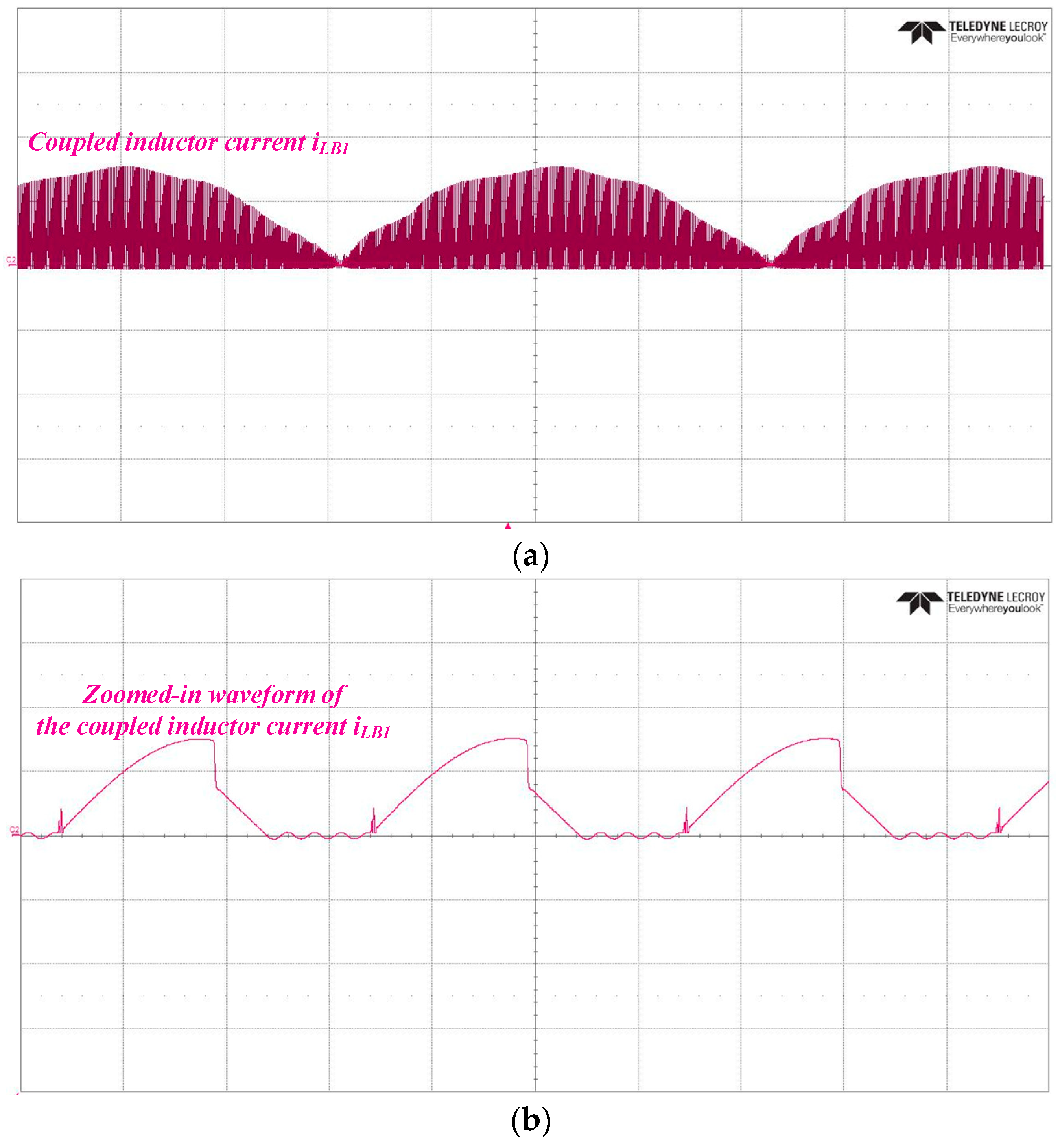
3. Experimental Results of the Proposed AC-DC LED Integrated Streetlight Driver

A photograph of the LED street light module used for the experiment in this paper is shown in Figure 12. The specifications of the LED streetlight module used in the experiment are as follows: the rated power is 165 W, the rated input voltage is 235 V, the rated input current is 700 mA, the luminous flux is 17,250 Lm, the luminous efficiency is 101 Lm/W, the color temperature is 4000 K, and the service life of the LED streetlight module is more than 50,000 h. The prototype circuit of the proposed driver has been successfully implemented and tested to power an LED streetlight module with a rated power of 165 W and an input utility line voltage of 110 V. Table 1 and Table 2 show the circuit specifications and key components utilized in the proposed single-stage AC-DC LED integrated streetlight driver, respectively.
The measured coupled inductor current iLB1 and its zoomed-in waveform are shown in Figure 13a,b, respectively; the results of the measured waveforms show that the current iLB1 operates in DCM. The measured coupled inductor current iLB4 and its zoomed-in waveform are shown in Figure 14a,b, respectively; the results of the measured waveforms show that the current iLB4 works in DCM. Figure 15 shows the measured switch voltage vDS2 and current iDS2; thus, it can be seen that ZVS occurs on the power switch, resulting in reduced switching losses.
Figure 16 gives the measured switch voltage vDS2 and the resonant inductor current iLr. The current iLr is lagged with respect to the voltage vDS2, so the series resonant tank is similar to an inductive load. Figure 17 shows the measured voltage VDC of the DC link capacitor CDC, and the measured mean value of VDC is 523.3 V. Figure 18 depicts the measured output voltage VO and current IO; their average values are approximately 235 V and 0.7 A, respectively. Table 3 shows the measured output voltage ripple and current ripple of the presented LED streetlight driver circuit. By using the AC-coupled mode of the digital oscilloscope, the measured mean value and peak-to-peak value of the output voltage are 235.47 V and 13.66 V, respectively. In addition, the mean value and peak-to-peak value of the output current are 703.84 mA and 45.75 mA, respectively. Moreover, the ripple factor of the output voltage (current) is obtained by dividing the peak-to-peak value by the mean value of the output voltage (current). In addition, the measured output voltage ripples and current ripples are 5.8% and 6.5%, respectively.
Figure 19 shows the measured waveforms of the input utility voltage vAC and current iAC. The input current iAC resembles a sine wave and is in phase with the input utility voltage vAC, which results in a high power factor. Figure 20 shows the measured input utility line current harmonics compared with the International Electrotechnical Commission (IEC) 61000-3-2 Class C standards [36] at an input utility line voltage of 110 V. The measured 2nd-, 3rd-, 5th-, 7th-, and 9th-order current harmonics are 0.0378%, 1.1081%, 1.2609%, 1.6779%, and 1.8712%, respectively, which are smaller than the respective standard values of 2%, 27%, 10%, 7%, and 5%, respectively. In addition, the current harmonics from the 11th to the 39th order are all smaller than the 3% required by the standard values. As a result, all measured input current harmonics meet the IEC requirements.
Table 4 shows the measured results of the proposed AC-DC LED integrated streetlight driver at an input utility line voltage of 110 V. As shown in Table 4, the measured circuit efficiency, power factor, and total harmonic distortion of the input current are 89.92%, 0.9875, and 2.3142%, respectively. Figure 21 presents a photograph of the single-stage LED integrated driver developed in this paper along with the streetlight module. In addition, the proposed integrated driver circuit is powered using an AC power source to supply energy to the LED streetlight module, and the voltage and current waveforms are observed through voltage and current probes using a digital oscilloscope.
Table 5 shows a comparison between the existing AC-DC single-stage LED integrated streetlight driver in [35], which has an input utility voltage of 220 V, and the proposed AC-DC single-stage LED integrated streetlight driver, which has an input utility voltage of 110 V, for powering 165 W rated LED modules with the same output. As can be seen from Table 5, the current THD of the proposed AC-DC LED integrated streetlight driver is better than the existing one when the measured power factor and circuit efficiency results are almost the same.

4. Conclusions

This paper proposed and implemented a single-stage LED street light driver that integrates an interleaved buck converter with a coupled inductor and a half-bridge series resonant converter cascaded with a full-bridge rectifier into a single power conversion stage with power factor correction and soft switching. In addition, the coupled inductor is designed to operate in discontinuous conduction mode, so that the driver circuit has a power factor correction function, and the half-bridge series resonant sub-circuit is designed to resemble inductive loading, so that the power switch has zero-voltage switching characteristics, reducing switching losses and improving the overall efficiency of the circuit. A 165 W prototype LED integrated streetlight driver has been developed and tested with an input mains voltage of 110 V. The experimental results of the proposed LED streetlight driver show low output voltage ripple (<6%), low output current ripple (<7%), high power factor (>0.98), low total harmonic distortion (<3%), turning on of the power switches at zero voltage, and high circuit efficiency (>89%), thus demonstrating the functionality of the presented LED streetlight driver. In the future, the AC-DC integrated LED streetlight driver proposed in this paper can be applied to LED streetlamps of different wattages by redesigning and adjusting circuit parameters.

Author Contributions

C.-A.C. developed and designed the circuit topology; H.-L.C., C.-H.C. and E.-C.C. arranged and performed circuit simulations; Z.-Y.K., C.-K.L. and S.-H.H. carried out the prototype driver circuit and measured as well as analyzed experimental results with guidance from C.-A.C.; C.-A.C. revised the manuscript for submission. All authors have read and agreed to the published version of the manuscript.

Funding

This research was funded by the National Science and Technology Council (NSTC) of Taiwan for its grant numbers MOST 110-2221-E-214-014 and MOST 111-2221-E-214-011.

Institutional Review Board Statement

Not applicable.

Informed Consent Statement

Not applicable.

Data Availability Statement

Not applicable.

Acknowledgments

The authors would like to express their greatest and sincerest thanks to the National Science and Technology Council (NSTC) of Taiwan for its grant numbers MOST 110-2221-E-214-014 and MOST 111-2221-E-214-011.

Conflicts of Interest

The authors declare no conflict of interest.

References

  1. Alharbi, F.; Almoshaogeh, M.I.; Ibrahim, A.H.; Haider, H.; Elmadina, A.E.M.; Alfallaj, I. Performance Appraisal of Urban Street-Lighting System: Drivers’ Opinion-Based Fuzzy Synthetic Evaluation. Appl. Sci. 2023, 13, 3333. [Google Scholar] [CrossRef]
  2. Ocana-Miguel, A.; Andres-Diaz, J.R.; Hermoso-Orzáez, M.J.; Gago-Calderón, A. Analysis of the Viability of Street Light Programming Using Commutation Cycles in the Power Line. Sustainability 2018, 10, 4043. [Google Scholar] [CrossRef] [Green Version]
  3. George Allwyn, R.; Al Abri, R.; Malik, A.; Al-Hinai, A. Economic Analysis of Replacing HPS Lamp with LED Lamp and Cost Estimation to Set Up PV/Battery System for Street Lighting in Oman. Energies 2021, 14, 7697. [Google Scholar] [CrossRef]
  4. Kerbiriou, C.; Barré, K.; Mariton, L.; Pauwels, J.; Zissis, G.; Robert, A.; Le Viol, I. Switching LPS to LED Streetlight May Dramatically Reduce Activity and Foraging of Bats. Diversity 2020, 12, 165. [Google Scholar] [CrossRef] [Green Version]
  5. Robles, J.; Zamorano, J.; Pascual, S.; Sánchez de Miguel, A.; Gallego, J.; Gaston, K.J. Evolution of Brightness and Color of the Night Sky in Madrid. Remote Sens. 2021, 13, 1511. [Google Scholar] [CrossRef]
  6. Adolfo, L.-M.J.; Jesús, H.-O.M.; Paulo, B. LCA Streetlight Study for Circular Economic to Local Scale. Proceedings 2020, 52, 6. [Google Scholar]
  7. Hamidi, S.N.A.; Omar, A.M.S.; Idin, M.A.M.; Samat, A.A.A.; Ramli, S.S.M.; Osman, M.K. Streetlight System Information Modelling and Management for Energy Reduction. In Proceedings of the 2021 6th IEEE International Conference on Recent Advances and Innovations in Engineering (ICRAIE), Kedah, Malaysia, 1–3 December 2021; pp. 1–7. [Google Scholar]
  8. Jayalakshmi, B.; Anjali, V.; Raj, R.N.; Nair, N.; Rahul, T.M. IoT Based Energy Efficient Automatic Streetlight. In Proceedings of the 2019 International Conference on Intelligent Computing and Control Systems (ICCS), Madurai, India, 15–17 May 2019; pp. 1478–1480. [Google Scholar]
  9. Marosy, G.; Kovács, Z.; Molnár, G.; Poppe, A. Diagnostics of LED-based streetlighting luminaires by means of thermal transient method. In Proceedings of the 2010 16th International Workshop on Thermal Investigations of ICs and Systems (THERMINIC), Barcelona, Spain, 6–8 October 2010; pp. 1–6. [Google Scholar]
  10. Lozano-Miralles, J.A.; Hermoso-Orzáez, M.J.; Gago-Calderón, A.; Brito, P. LCA Case Study to LED Outdoor Luminaries as a Circular Economy Solution to Local Scale. Sustainability 2020, 12, 190. [Google Scholar] [CrossRef] [Green Version]
  11. Novak, T.; Zeilinger, H.; Schaat, S. Increasing energy efficiency with traffic adapted intelligent streetlight management. In Proceedings of the IECON 2013–39th Annual Conference of the IEEE Industrial Electronics Society, Vienna, Austria, 10–13 November 2013; pp. 6087–6092. [Google Scholar]
  12. Ramli, R.M.; Arief, Y.Z.; Aziz, P.D.A. Application of LED technology into public road lighting in Malaysia for replacing the high pressure sodium vapour lighting. In Proceedings of the 2015 International Conference on Sustainable Energy Engineering and Application (ICSEEA), Bandung, Indonesia, 14–16 October 2015; pp. 76–81. [Google Scholar]
  13. Cheng, C.-A.; Cheng, H.-L.; Chang, C.-H.; Chang, E.-C.; Hung, W.-S.; Lai, C.-C.; Lan, L.-F. A Single-Stage High Power Factor Power Supply for Providing an LED Street-Light Lamp Featuring Soft-Switching and Bluetooth Wireless Dimming Capability. Energies 2021, 14, 477. [Google Scholar] [CrossRef]
  14. Hermoso-Orzáez, M.J.; Lozano-Miralles, J.A.; Lopez-Garcia, R.; Brito, P. Environmental Criteria for Assessing the Competitiveness of Public Tenders with the Replacement of Large-Scale LEDs in the Outdoor Lighting of Cities as a Key Element for Sustainable Development: Case Study Applied with PROMETHEE Methodology. Sustainability 2019, 11, 5982. [Google Scholar] [CrossRef] [Green Version]
  15. Bhairi, M.N.; Kangle, S.S.; Edake, M.S.; Madgundi, B.S.; Bhosale, V.B. Design and implementation of smart solar LED street light. In Proceedings of the 2017 International Conference on Trends in Electronics and Informatics (ICEI), Tirunelveli, India, 11–12 May 2017. [Google Scholar]
  16. Aoyama, Y.; Yachi, T. An LED Module Array System Designed for Streetlight Use. In Proceedings of the 2008 IEEE Energy 2030 Conference, Atlanta, GA, USA, 17–18 November 2008; pp. 1–5. [Google Scholar]
  17. Singh, A.; Marathey, P.; Mukhopadhyay, I. Energy positive solar LED streetlight system. In Proceedings of the 2017 International Conference on Energy, Communication, Data Analytics and Soft Computing (ICECDS), Chennai, India, 1–2 August 2017. [Google Scholar]
  18. Hong, S.-I.; In, C.-G.; Ryu, H.-S.; Park, J.-C.; Yoon, D.-H.; Lin, C.-H. A development of LED-IT-sensor integration streetlight management system on Ad-hoc. In Proceedings of the TENCON 2011–2011 IEEE Region 10 Conference, Bali, Indonesia, 21–24 November 2011; pp. 1331–1335. [Google Scholar]
  19. Jha, A.; Kumar, M. Improved Power Quality LED Driver with SELV Norms for Streetlight Application. In Proceedings of the 2018 IEEE International Conference on Power Electronics, Drives and Energy Systems (PEDES), Chennai, India, 18–21 December 2018; pp. 1–6. [Google Scholar]
  20. Jiang, X. Innovation to brisbane city council street lighting system with solar powered LED: A techno-economic feasibility study. In Proceedings of the 2016 Australasian Universities Power Engineering Conference (AUPEC), Brisbane, QLD, Australia, 25–28 September 2016; pp. 1–6. [Google Scholar]
  21. Jha, A. Smart LED Streetlighting System with Improved Power Quality and Low Standby Consumption. In Proceedings of the 2019 3rd International Conference on Recent Developments in Control, Automation & Power Engineering (RDCAPE), Noida, India, 10–11 October 2019; pp. 131–136. [Google Scholar]
  22. Zhang, J.; Zhu, M.; Hao, C.; Tang, J.; Yang, Q. Reliability analysis of high-power LED streetlight. In Proceedings of the 2012 9th International Conference on Fuzzy Systems and Knowledge Discovery, Chongqing, China, 29–31 May 2012; pp. 2755–2758. [Google Scholar]
  23. Wikipedia, the Free Encyclopedia. “Power Factor”. Available online: https://en.wikipedia.org/wiki/Power_factor#Active_PFC (accessed on 22 March 2023).
  24. Wikipedia, the Free Encyclopedia. “Switched-Mode Power Supply”. Available online: https://en.wikipedia.org/wiki/Switched-mode_power_supply#Types (accessed on 22 March 2023).
  25. Naraharisetti, K.; Green, P.B. Design of 200 W Boost PFC Plus HB LLC Resonant Converter with IR1155, IRS27952 and IR11688. Application Note, Infineon. Available online: http://www.infineon.com (accessed on 26 February 2023).
  26. Arias, M.; Lamar, D.G.; Linera, F.F.; Balocco, D.; Diallo, A.A.; Sebastián, J. Design of a Soft-Switching Asymmetrical Half-Bridge Converter as Second Stage of an LED Driver for Street Lighting Application. IEEE Trans. Power Electron. 2012, 27, 1608–1621. [Google Scholar] [CrossRef]
  27. Gao, S.; Wang, Y.; Zhang, S.; Xu, D. A two-stage quasi-resonant dual buck LED driver with digital control method. In Proceedings of the 2016 IEEE Industrial Electronics and Applications Conference (IEACon), Kota Kinabalu, Malaysia, 20–23 November 2016; pp. 36–41. [Google Scholar]
  28. Xie, X.; Ye, M.; Cai, Y.; Wu, J. An optocouplerless two-stage high power factor LED driver. In Proceedings of the 2011 Twenty-Sixth Annual IEEE Applied Power Electronics Conference and Exposition (APEC), Fort Worth, TX, USA, 6–11 March 2011; pp. 2078–2083. [Google Scholar]
  29. Athalye, P.; Harris, M.; Negley, G. A two-stage LED driver for high-performance high-voltage LED fixtures. In Proceedings of the 2012 Twenty-Seventh Annual IEEE Applied Power Electronics Conference and Exposition (APEC), Orlando, FL, USA, 5–9 February 2012; pp. 2385–2391. [Google Scholar]
  30. Khatua, M.; Pervaiz, S.; Afridi, K.K. Control of a Merged-Energy-Buffer based Two-Stage Electrolytic-Free Offline LED Driver. In Proceedings of the 2019 20th Workshop on Control and Modeling for Power Electronics (COMPEL), Toronto, ON, Canada, 17–20 June 2019; pp. 1–6. [Google Scholar]
  31. Wang, Y.; Qi, N.; Guan, Y.; Cecati, C.; Xu, D. A Single-Stage LED Driver Based on SEPIC and LLC Circuits. IEEE Trans. Ind. Electron. 2017, 64, 5766–5776. [Google Scholar] [CrossRef]
  32. Wang, Y.; Guan, Y.; Huang, J.; Wang, W.; Xu, D. A Single-Stage LED Driver Based on Interleaved Buck-Boost Circuit and LLC Resonant Converter. IEEE J. Emerg. Sel. Top. Power Electron. 2015, 3, 732–741. [Google Scholar] [CrossRef]
  33. Ma, J.; Wei, X.; Hu, L.; Zhang, J. LED Driver Based on Boost Circuit and LLC Converter. IEEE Access 2018, 6, 49588–49600. [Google Scholar] [CrossRef]
  34. Cheng, C.-A.; Cheng, H.-L.; Chang, C.-H.; Chang, E.-C.; Kuo, Z.-Y.; Lin, C.-K.; Hou, S.-H. A Novel AC-DC LED Integrated Streetlight Driver with Power-Factor-Correction and Soft-Switching Functions. In Proceedings of the 2021 IEEE International Future Energy Electronics Conference (IFEEC), Taipei, Taiwan, 16–19 November 2021; pp. 1–3. [Google Scholar]
  35. Cheng, C.-A.; Chang, C.-H.; Cheng, H.-L.; Tseng, C.-H.; Chung, T.-Y. A Single-Stage High-Power-Factor Light-Emitting Diode (LED) Driver with Coupled Inductors for Streetlight Applications. Appl. Sci. 2017, 7, 167. [Google Scholar] [CrossRef] [Green Version]
  36. Wikipedia, the Free Encyclopedia. “IEC 61000-3-2”. Available online: https://en.wikipedia.org/wiki/IEC_61000-3-2 (accessed on 26 June 2023).
Figure 1. Block diagram of the conventional two-stage LED streetlight driver with power-factor-correction and soft-switching characteristic.
Sustainability 15 10579 g001
Figure 2. Block diagram of the single-stage integrated LED streetlight driver with power-factor-correction and soft-switching characteristic.
Sustainability 15 10579 g002
Figure 3. The proposed single-stage AC-DC LED streetlight driver with power factor correction and soft-switching features.
Sustainability 15 10579 g003
Figure 4. Equivalent circuit of the proposed single-stage LED streetlight driver while analyzing the operational modes.
Sustainability 15 10579 g004
Figure 5. Equivalent circuit of operational mode 1 in the proposed LED integrated streetlight driver.
Sustainability 15 10579 g005
Figure 6. Equivalent circuit of operational mode 2 in the proposed LED integrated streetlight driver.
Sustainability 15 10579 g006
Figure 7. Equivalent circuit of operational mode 3 in the proposed LED integrated streetlight driver.
Sustainability 15 10579 g007
Figure 8. Equivalent circuit of operational mode 4 in the proposed LED integrated streetlight driver.
Sustainability 15 10579 g008
Figure 9. Equivalent circuit of operational mode 5 in the proposed LED integrated streetlight driver.
Sustainability 15 10579 g009
Figure 10. Equivalent circuit of operational mode 6 in the proposed LED integrated streetlight driver.
Sustainability 15 10579 g010
Figure 11. Key waveforms of the presented LED driver for streetlight applications.
Sustainability 15 10579 g011
Figure 12. Photograph of the LED street light module used for the experiment in this paper.
Sustainability 15 10579 g012
Figure 13. (a) Measured coupled inductor current iLB1 (5 A/div); time scale: 2 ms/div. (b) Zoomed-in waveform of the coupled inductor current iLB1 (5 A/div); time scale: 10 μs/div.
Sustainability 15 10579 g013
Figure 14. (a) Measured coupled inductor current iLB4 (5 A/div); time scale: 10 μs/div. (b) Zoomed-in waveform of the coupled inductor current iLB4 (5 A/div); time scale: 10 μs/div.
Sustainability 15 10579 g014
Figure 15. Measured switch voltage vDS2 (200 V/div) and current iDS2 (5 A/div); time scale: 10 μs/div.
Sustainability 15 10579 g015
Figure 16. Measured switch voltage vDS2 (200 V/div) and resonant inductor current iLr (1 A/div); time scale: 10 μs/div.
Sustainability 15 10579 g016
Figure 17. Measured voltage VDC (500 V/div) of the DC link capacitor CDC; time scale: 500 μs/div.
Sustainability 15 10579 g017
Figure 18. Measured output current IO (0.5 A/div) and voltage VO (100 V/div); time scale: 50 μs/div.
Sustainability 15 10579 g018
Figure 19. Measured input utility line voltage vAC (100 V/div) and current iAC (5 A/div); time scale: 5 ms/div.
Sustainability 15 10579 g019
Figure 20. Measured harmonics of the input utility line current in comparison with the IEC 61000-3-2 class C standard.
Sustainability 15 10579 g020
Figure 21. Photograph of the single-stage LED integrated driver developed in this paper along with the streetlight module and the devices used for the measurements.
Sustainability 15 10579 g021
Table 1. Circuit specifications of the proposed AC-DC LED integrated streetlight driver.
ParameterValue
Input Utility Line Voltage vAC110 V
Output Rated Power PO165 W
Output Rated Voltage VO235 V
Output Rated Current IO0.7 A
Table 2. Key components used in the proposed AC-DC LED integrated streetlight driver.
ComponentValue
Capacitors Cin1, Cin2220 nF
Filter Inductor Lf3 mH
Filter Capacitor Cf330 nF/630 V
Diodes Dr1, Dr2, Dr3, Dr4,KBU 810
Coupled Inductors LB1, LB4; LB2, LB3170 μH; 133 μH
Diodes DB1, DB2, DB3, DB4, Do1, Do2, Do3, Do4MUR460
Power Switches S1, S2K20J60U
DC-Linked Capacitor CDC470 μF/450 V
Resonant Inductor Lr162 μH
Resonant Capacitor Cr2 μF/250 V
Output Capacitor Co220 μF/450 V
Table 3. Measured output voltage ripple and current ripple in the presented LED streetlight driver circuit.
ParametersValues
Mean value of the output voltage235.47 V
Peak-to-peak value of the output voltage13.66 V
Ripple factor of the output voltage5.8%
Mean value of the output current703.84 mA
Peak-to-peak value of the output current45.75 mA
Ripple factor of the output current6.5%
Table 4. Measured results of the proposed AC-DC LED integrated streetlight driver.
ParameterValue
Input Utility-Line Voltage vAC110 V
Circuit Efficiency89.92%
Power Factor0.9875
Total Harmonic Distortion of Input Current2.3142%
Table 5. Comparisons between the existing single-stage AC-DC LED integrated streetlight driver in [35] and the proposed one.
ItemExisting AC-DC LED Integrated Streetlight Driver in Reference [35]Proposed
AC-DC LED Integrated Streetlight Driver
Circuit TopologyIntegration of interleaved buck-boost converter with a coupled inductor and a HB-SR converter with a FB rectifierIntegration of interleaved buck converter with a coupled inductor and a HB-SR converter with a FB rectifier
Input Utility Line Voltage220 V110 V
Output Power165 W (235 V/0.7 A)165 W (235 V/0.7 A)
Number of Required Diodes1212
Number of Required Capacitors66
Number of Required Magnetic Components44
Measured Power Factor0.9920.9875
Measured Current THD6.55%2.3142%
Measured Circuit Efficiency90.22%89.92%
Disclaimer/Publisher’s Note: The statements, opinions and data contained in all publications are solely those of the individual author(s) and contributor(s) and not of MDPI and/or the editor(s). MDPI and/or the editor(s) disclaim responsibility for any injury to people or property resulting from any ideas, methods, instructions or products referred to in the content.

