Abstract
The realistic determination of damage estimation and building performance depends on target displacements in performance-based earthquake engineering. In this study, target displacements were obtained by performing pushover analysis for a sample reinforced-concrete building model, taking into account 60 different peak ground accelerations for each of the five different stories. Three different target displacements were obtained for damage estimation, such as damage limitation (DL), significant damage (SD), and near collapse (NC), obtained for each peak ground acceleration for five different numbers of stories, respectively. It aims to develop an artificial neural network (ANN)-based sustainable model to predict target displacements under different seismic risks for mid-rise regular reinforced-concrete buildings, which make up a large part of the existing building stock, using all the data obtained. For this purpose, a hybrid structure was established with the particle swarm optimization algorithm (PSO), and the network structure’s hyper parameters were optimized. Three different hybrid models were created in order to predict the target displacements most successfully. It was found that the ANN established with particles with the best position revealed by the hybrid models produced successful results in the calculation of the performance score. The created hybrid models produced 99% successful results in DL estimation, 99% in SD estimation, and 99% in NC estimation in determining target displacements in mid-rise regular reinforced-concrete buildings. The hybrid model also revealed which parameters should be used in ANN for estimating target displacements under different seismic risks.
1. Introduction
Major structural damages and loss of life due to these damages during earthquakes revealed the necessity and importance of performance-based design and evaluation of structures [1,2,3]. The first important product of these studies is the “Vision 2000 Report” published in 1995 by the California Society of Structural Engineers (SEAOC, 1995) [4]. Afterward, the performance-based design and evaluation of structures found their place in earthquake regulations over time. In performance-based earthquake engineering, it is very significant to define target displacements for damage estimation when particular performance limits of structural members are achieved.
In the performance-based design and evaluation method, it is possible to quantitatively determine the damage levels that may occur in the structural system elements under design ground motion. For each relevant element, it can be checked whether this damage remains below acceptable damage levels. Acceptable damage limits have been defined to be consistent with the predicted performance targets at various earthquake levels [5]. Performance-based design’s primary objective is to ascertain the structural requirement in structures exposed to ground motion. Correct specification of ground motion characteristics and their connections to structural demand is necessary for accurate structural demand determination [6,7,8]. With the definition of strong ground motion in objective and quantitative ways, it is possible to evaluate the effects of earthquakes in a particular place. The purpose of strong ground motion measurements is to measure ground acceleration as a function of time or frequency and to monitor the performance of structures during earthquakes. In this context, a useful tool for describing the properties of earthquake ground motion and its consequences on structures is the seismic spectrum. The graph that represents the period (or frequency) maximum response of a single-degree-of-freedom structure under the associated seismic ground motion component is known as the earthquake response spectrum. The most common criterion used to determine the amplitude of strong ground motion is the “peak ground acceleration (PGA)”.
Modern pre-earthquake disaster management includes seismic risk analysis for every region, and it is a crucial tool for decision-makers [9,10,11,12,13,14,15]. The most widely used determinant in earthquake hazard determinations is the maximum horizontal ground acceleration, which we abbreviate as PGA. One of the most important reasons for using the PGA value is that the proposed design spectrum shapes in earthquake specifications can be scaled with PGA (or parameters that can be associated with PGA, such as “effective acceleration”). Within the scope of this study, structural analyses were carried out using 60 different PGA values. There are many studies on the effect of PGA on structural analysis and evaluation [16,17,18,19,20]. In this study, besides PGA, another variable considered is the total number of stories in the building [21,22]. In addition, different parameters in reinforced concrete structures with various stories have been examined comparatively [23,24,25,26].
Artificial neural networks (ANN), which is one of the machine learning methods, and particle swarm optimization (PSO), which is used in solving multidimensional problems, are frequently used in many areas [27,28,29,30,31,32]. In structural and earthquake engineering applications, these techniques have a critical impact on areas such as simulation, modeling, optimization, regression, and classification [33,34]. Some studies have also been carried out to predict the structural properties of reinforced concrete buildings under seismic loads, such as earthquakes with ANN [35,36,37,38,39,40]. Another algorithm with nonlinear static and dynamic analyzes used in the design optimization of the structures is PSO [41]. In some studies, ANN and PSO were used together [42,43,44,45,46]. In addition, there are several recent studies that present an analytical–mechanical-based procedure to estimate the seismic behavior of existing buildings [47,48,49,50]. Due to their results, they stated that predictions can be made with reasonable accuracy.
The realistic determination of the earthquake performance of the buildings depends on the target displacements. In order to obtain the target displacements within the scope of this study, structural analyses were carried out for a sample reinforced concrete building with five different mid-rise stories (4, 5, 6, 7, and 8). In order to reveal the effects of different seismic risks on target displacements in the structural analysis, 60 different peak ground accelerations (PGAs) in the range of 0.01 g to 1.19 g were taken into account. For each story number and PGA value, three different limit situations were taken into account, namely, damage limitation (DL), significant damage (SD), and near collapse (NC) predicted in Eurcode-8, which is widely used around the world. In the study, firstly, the period, base shear force, and elastic and effective stiffness values for the number of stories were obtained and compared. Then, target displacements were obtained for each story and PGA. This study aims to develop a feedforward backpropagation ANN model to predict target displacements under different seismic risks for mid-rise regular reinforced concrete buildings in the most successful way. For this purpose, a PSO-ANN-based model is presented for the optimization of the hyper parameters used in the network structure. It is expected that the proposed hybrid structure will optimize the number of hidden layers, the number of neurons in each layer, the activation functions in the neuron cells, the training function of the network, and obtain the network parameters that should be used in such a problem in the ANN model that is intended to be developed and will make the best prediction. The change in these parameters directly affects the performance of the network in estimation. The presented model was run on 300 data obtained for five different stories separately for the estimation of each DL, SD, and NC value, and the findings were presented controversially. The flow chart of the paper is shown in Figure 1.

Figure 1.
Flow chart of this study.
This paper addresses an important issue from the perspective of sustainability. The construction industry faces challenges related to sustainability, such as energy consumption, depletion of natural resources, and environmental impacts. Therefore, it is of great importance to consider sustainability principles in the design and construction processes of buildings. The model presented in the article offers an approach that combines artificial neural networks and particle swarm optimization algorithms for determining target displacements in buildings. This model is applicable to mid-rise regular reinforced-concrete structures and assists in optimizing their structural performance. Accurately determining target displacements enhances the resilience of buildings, making them safer when exposed to earthquakes or other external forces.
Artificial neural networks provide a learning and prediction mechanism to simulate the behavior of the structure. Real-time data obtained from the combination of structural parameters and loads are used to train the artificial neural network. After the training process, the model can predict the responses of the structure and determine the target displacements. The particle swarm optimization algorithm is effective in optimizing the target displacements. The swarm of particles moves in the solution space, representing the design parameters of the structure. Each particle seeks the best solution by evaluating its current position and its distance from the target. By sharing the best solutions and learning from each other, the particles navigate the solution space. In this way, the optimization process is performed to obtain the best target displacements. The significance of the article in terms of sustainability lies in enhancing the resilience of structures and effectively managing energy and material usage through the application of the model. Accurately determining target displacements helps prevent unnecessary material usage and increases energy efficiency. Thus, an important step is taken toward a sustainable construction industry.
2. Description of the Numerical Models
The Seismostruct computer program was used for numerical analysis [51]. Pushover analyses were performed in the structural analyses for the reference RC building models with 4-stories, 5-stories, 6-stories, 7-stories, and 8-stories, respectively. The blueprint of the story was taken the same in all structural buildings and is shown in Figure 2. The sample reinforced-concrete building is modeled symmetrically and regularly in both directions.
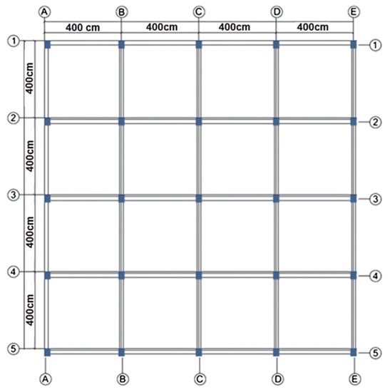
Figure 2.
The blueprint of the sample RC building model.
All building models were created using infrmFBPH (force-based plastic hinge frame elements), which were used for structural components such as beams and columns. These components only allow plasticity to extend a fixed distance and model force-based extensional flexibility. According to Antoniou and Pinho [52], the ideal number of fibers in the section should be adequate to model the stress–strain distribution in the section. The designated fiber elements for the chosen sections amount to 100 in total. For partitions of this type, this value is sufficient. The selected value for the plastic-hinge length (Lp/L) is 16.67%. A fully fixed column footing and a free top end were produced by setting the column’s boundary conditions in accordance with the cantilever boundary conditions. The footing’s boundary condition was fixed on the surface. In all numerical models, the story height is assumed to be 3 m. Each of these spans is 4 m in each direction and was taken into consideration for the model RC building, which was chosen to be symmetrical in the X and Y directions. In Figure 3, the 2D building models are displayed. The 4-story, 5-story, 6-story, 7-story, and 8-story building models were taken into account in order to represent the mid-rise housing structures, which constitute a large part of the existing housing stock in Türkiye.
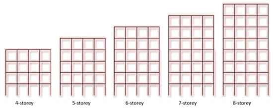
Figure 3.
Two-dimensional models of the reference RC structure for various numbers of stories.
Table 1 shows the RC building model’s structural characteristics. All these structural characteristics are taken the same in all building models except target displacement.

Table 1.
Structural properties of reference RC building model.
The target displacement is one of the critical data used to decide the earthquake performance of the buildings. The accuracy of these displacements allows for more realistic damage estimation and performance of structures. Within the scope of this study, target displacements were obtained by taking into account the boundary conditions specified in Eurocode 8 (Part 3) [53,54], which is more widely used around the world. Three limit states were envisaged in this code such as damage limitation (DL), significant damage (SD), and near collapse (NC). DL corresponds only lightly damaged; damage to non-structural components is economically repairable for a 20% probability exceedance in 50 years. SD corresponds to significantly damaged; some residual strength and stiffness, non-structural components damaged, and uneconomic to repair for 10% probability exceedance in 50-year. NC states for heavily damaged; very low residual strength and stiffness, large permanent drift but still standing for 2% probability exceedance in 50-year. A sample representation of these limit states on a pushover curve is shown in Figure 4. A pushover curve is obtained by combining the intersecting points on an interaction diagram of the roof displacement values corresponding to the base shear forces. The yield displacement is represented by the first value, while the intermediate displacement and target displacement, respectively, are represented by the second and third values.
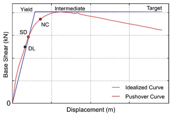
Figure 4.
Target displacement graphs of the idealized curves and typical pushover.
According to Eurocode-8, the building importance class was selected as the IV class, as stated in Table 2. In order to make comparisons, ZC, which is the average soil class in Eurocode-8, was chosen as the local soil class that is given in Table 3.

Table 2.
Importance class for reference RC building model [53].

Table 3.
Properties of local soil classes [53].
Pushover analysis was used in this study to carry out structural analyses. One of the most used methods for determining a building’s seismic capacity is pushover analysis [55]. This approach offers a useful tool to assess how a building will behave in the inelastic zone. By using this analysis’s base shear force and peak displacements, the building’s capacity curve is determined. In order to obtain this curve, the lateral forces are incrementally raised until the building’s roof displacement achieves a target displacement. The pushover curve increases the structure from zero to unstable by geometrically combining the intersection points on an interaction diagram of the roof displacement corresponding to the base shear forces under the imposed load. By converting the pushover curve to modal capacity diagrams and figuring out the structure’s maximum inelastic displacement capacity, the pushover curve becomes meaningful [56,57,58,59,60]. The flow chart of the pushover analysis procedure is given in Figure 5.
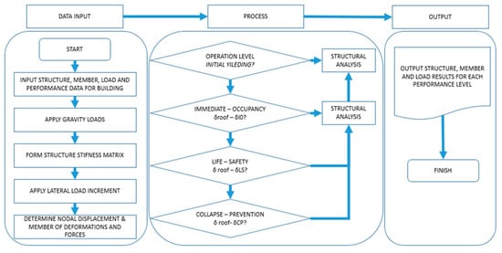
Figure 5.
Flowchart of typical pushover analysis (adopted from [61,62]).
3. Structural Analysis Results
In this study, the comparison of the period, base shear force, and elastic and effective stiffness values obtained as a result of the eigenvalue and pushover analyses performed for different stories are given in Table 4. The comparison of all these obtained values is shown in Figure 6.

Table 4.
Comparison of the values obtained for buildings with different stories.
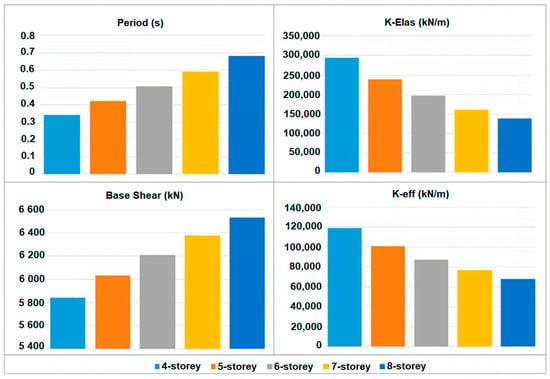
Figure 6.
Comparison of the period, base shear force, and elastic and effective stiffness values for different stories.
As the number of floors of RC structures with the same structural properties increases, the stiffness value decreases, and accordingly, the period value increases. The comparison of the pushover curves obtained for different floor numbers as a result of the structural analysis was made in Figure 7.
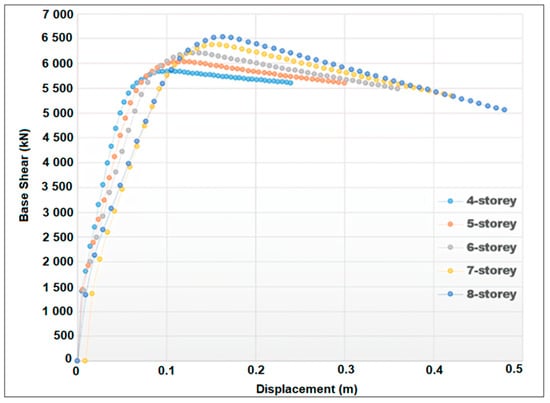
Figure 7.
Comparison of pushover curves for different stories.
Another variable considered within the scope of the study is PGA. In order to reveal different seismic risks, 60 different PGA values were taken into account by increasing 0.01 g in the range of 0.01–1.19 g. Structural analyzes were carried out separately to obtain three different limit states specified in Eurocode-8 for each increment and five different stories. The target displacement values obtained for 60 different PGA values considered within the scope of the study are shown in Table 5. All these values obtained in the table form the data set for the machine learning used in the study.

Table 5.
Limit displacement values obtained for different story numbers and PGA.
With the increase in the number of floors and seismic risk in reinforced concrete structures, the target displacement values have also increased. The increase in the number of stories of a building under the influence of an earthquake and the increase in the period value depending on the decrease in the stiffness value indicates that the structure will be exposed to more horizontal displacement. Therefore, as the number of floors increases, the target displacement values will increase accordingly. In addition, the high seismic risk means that the effect of the earthquake on the structure will increase, and it will cause more horizontal displacement.
4. Artificial Neural Network (ANN)
ANN is an artificial intelligence technology inspired by the working principles of the human brain [28]. ANNs are designed as networks of complex mathematical operations used to learn and generalize data. These networks contain many tiny artificial neurons interconnected by billions of junctions, and these neurons work together to sense, classify, or predict data patterns. A simple ANN structure is shown in Figure 8.
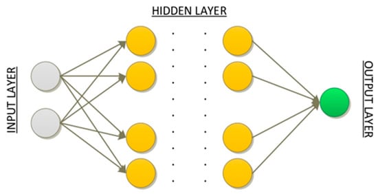
Figure 8.
ANN network structure.
In the ANN network structure presented in Figure 8, information enters the network from the input layer and proceeds to the output layer. Neuron cells in each layer multiply the information from the previous layer by their weight and pass it through an activation function by adding its own bias value. If there is information passed through the activation function, it is transmitted to the next layer. The information becomes meaningful in the last output layer, and the network generates output information for the input information.
4.1. Particle Swarm Optimization Algorithm
PSO is an optimization technique that mimics the behavior of a swarm in nature. In PSO, each individual in a population represents a part of a solution, and it is aimed to find a better solution as a result of interactions between individuals [31]:
- Set the initial parameters and create the population;
- Identify each individual’s best solution so far (pbest) and the global best solution (gbest);
- Calculate the new velocities of each particle and swap the particles;
- Update pbest and gbest values;
- Go back to step 3 for the number of iterations.
PSO is a population-based algorithm. Each particle in the population is a solution to the problem to be solved. In each iteration, the position of the particle is changed in the solution space, as shown in Equations (1) and (2).
In Equation (1), the value of Vkl(t + 1) represents the velocity of the t iteration in the first dimension of k particles. The pbestkl(t) value shows the best position of k particles in the first dimension in the t iteration. The value of Xkl (t) shows the position of the k particle in the first dimension in the t iteration. The value of gbest(t) shows the best position in the first dimension in the t iteration. The W value in the equation shows the momentum coefficient, and the C1 and C2 constants are the learning parameters used to find the best solution. The value of Xn (t) given in Equation (2) shows the position of the n particle in the t iteration.
4.2. Hybrid Model and Results
In this part of the study, a hybrid structure was created using PSO and ANN to most successfully predict target displacements under different seismic risks for mid-rise regular reinforced concrete buildings. In the data set presented in Table 6, the input values are in the ANN models created with the PGA and Floor number. DL, SD, and NC values form the output information with hybrid structures that are created differently with these input values. With these hybrid structures, the parameters that should be used in the most successful ANN structures are determined for the estimation of DL, SD, and NC values. In the study, the data set is divided into 70% training data and 30% test data. Thus, they learn models with 210 pieces of data and make predictions for 70 data they have never encountered. The generated PSO-ANN hybrid structure is shown in Figure 9.

Table 6.
Parameters and limit values used in the hybrid model.
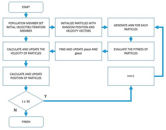
Figure 9.
Created PSO-ANN hybrid structure.
The hybrid structure presented in Figure 9 was run separately for DL, SD, and NC values. Within the hybrid model, each particle contains hyper parameters used in the ANN network structure. These parameters are the number of hidden layers, the number of neurons in each hidden layer, the activation functions of neurons in each layer, and the training function of the network. The training function and activation functions used in the ANN network structure and the limit values used in the hybrid structure are shown in Table 6.
Activation functions and training functions presented in Table 6 are different functions used in ANNs. The use of these functions directly affects the performance of the ANN structure. In addition, while increasing the number of hidden layers and neurons, the response time of the system increases in experimental studies. Therefore, as a result of the experimental studies, the upper limit of the number of hidden layers and neurons was determined as 6.
In the hybrid model, each particle forms an ANN structure and is individually measured according to its fitness function. In the hybrid model, each particle forms an ANN structure, and each particle is individually measured according to its fitness function. In the hybrid model, the population was created as the first step. The values given in Table 6 were taken into account when creating the population. Other parameters used in PSO were determined as a result of studies, as presented in Table 7.

Table 7.
PSO parameters.
As can be seen in Table 7, the momentum constant (w) value was taken as 1 in order to eliminate sudden velocity changes and not destroy the velocity concept in the algorithm, and C1 and C2 values were chosen to be C2 + C2 4 [31]. The algorithm converges as the number of iterations increases. As a result of the experimental studies, the number of iterations was determined as 50.
Since each particle creates an ANN structure within itself, “network parameters to be optimized” constitute the solution space. According to the initial parameters determined as the first step, 20 particles were created. In the next step in the hybrid model, the pbest value of each generated particle and the gbest value in that iteration were calculated as presented in Equation (3).
In Equation (3), represents the fitness value of the i-th particle, represents the ANN network structure established with the i-th particle, and MSE represents the mean squared error. After obtaining the pbest and gbest values of each particle, the velocities of the particles were updated, as shown in Equation (1), and the positions of the particles according to the calculated velocity values were updated, as shown in Equation (2).
For each DL, SD and NC value of the hybrid model, 50 iterations were run separately. After 50 iterations, the particles in the best position for DL, SD and NC values were determined according to gbest values. The best particle positions determined are presented in Table 8.

Table 8.
Particles values in the gbest.
Table 8 shows that different network structures should be created to estimate different data using the same input data. As seen in the three models, the parameters used in the network structure are different. ANN structures established with the best particles presented in Table 8 are shown in Figure 10. In Figure 10, architectures were created with the specified parameters to achieve the most successful results in three models.

Figure 10.
ANN structures established with particles with the best position.
The successes of the ANN structures, which are presented in Figure 7 and contain the hyper parameters obtained with the hybrid model, during the testing phase are shown in Figure 11.
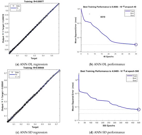
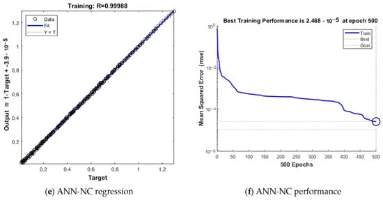
Figure 11.
Training and test success graphs of the models.
The regression graphs of the ANN structures, which are presented in Figure 11a,c,e, and which are calculated with the hybrid model, are shown. In the regression graphs of all three models, the target line and the fit lines overlap. The data concentrate on these overlapping lines. It shows that the learning success of these models is high. The performance graphs of the ANN structures obtained with the hybrid model and presented in Figure 11b,d,f are shown. In all three graphs, it is seen that the MSE values of the networks decrease during the iterations. The performances of the networks are determined according to the MSE value. These graphs show that the models are successful and their predictive power on the data they have not encountered.
As a result of this study, testing was carried out on 70 pieces of data, which completed their training with 210 data and did not encounter each model whose educational achievements are presented in Figure 11. As a result of the tests, the success of the models in their predictions of the new data is presented in Table 9.

Table 9.
Test performances of models.
The MSE values of the models are seen in the estimation processes performed on the test data presented in Table 9 The closer the MSE value is to zero, the greater the success of the model in predicting. The results show that the ANN models created with the parameters obtained with the hybrid model produced successful results. There is no comparable algorithm to the presented hybrid model. The comparison of the proposed model has been discussed in the study using real data in a controversial manner, and the obtained results have been presented.
5. Conclusions
It is important to know the target displacements in order to know the damage estimation and possible performances of the structures under the effect of earthquakes. Within the scope of this study, three different target displacements were obtained by choosing the number of stories and seismic risk as variables as a result of structural analysis. For this purpose, structural analyses were carried out by considering five different story numbers and 60 different PGA values. In RC structures with the same structural features, as the number of stories increases, the period increases, and accordingly, the stiffness decreases. In addition, with the increase in PGA values, the target displacements increased. Since the horizontal drifts expected from the structure increase depending on the magnitude of the earthquake, the target displacement values predicted for the performance level will also increase. As a result of this, accurately obtaining the target displacements to be predicted under the effect of any earthquake in the building will enable the performance levels of the building to be determined more realistically. Within the scope of this study, 300 result values obtained from the results of the structural analysis were used as a data set, and target displacement values were tried to be estimated with artificial neural networks. For this purpose, a hybrid structure was established in order to predict the target displacements under different seismic risks in the most successful and easy way for mid-rise regular reinforced concrete buildings. Owing to this hybrid structure, the ANN hyper parameters that should be used in the most successful estimation of DL, SD, and NC values were optimized using PSO. In light of the findings, it was observed that the success of network structures established with different network parameters on the same data is different. ANN network structures established by the most successful particles obtained with the hybrid model produced successful results in estimating DL, SD, and NC values. In addition, thanks to the created hybrid structure, the network parameters to be used in such a problem were determined separately for each value.
In the study, hybrid models were created to determine target displacements in regular mid-rise reinforced concrete buildings with 99% success in DL estimation. In addition, 99% success was achieved in the estimation of SD. In addition, hybrid models achieved a 99% success rate in NC prediction. These results demonstrate the effectiveness of hybrid models in detecting target displacements in mid-rise regular reinforced concrete buildings.
In conclusion, the article “A Hybrid Artificial Neural Network—Particle Swarm Optimization Algorithm Model for the Determination of Target Displacements in Mid-rise Regular Reinforced-Concrete Buildings” presents a model for determining target displacements in mid-rise regular reinforced-concrete structures with a focus on sustainability. By combining artificial neural networks and particle swarm optimization algorithms, the model aids in optimizing structural performance and effectively managing resources. This article can be considered an important step toward achieving sustainability goals in the construction industry.
The study was carried out only for regular reinforced concrete buildings. This study can be used as a resource for reinforced-concrete buildings with different irregularities. In addition, the study was carried out only for mid-rise buildings. This study can be a base for buildings with more number stories.
Author Contributions
Conceptualization, M.F.I., F.A., M.A.B., M.H.-N., R.İ. and E.I.; methodology, E.I., M.A.B., M.F.I., E.H. and F.A.; software, M.A.B. and E.I.; validation, M.H.-N., D.R., M.F.I., E.I. and E.H.; formal analysis, F.A., R.İ., E.H. and D.R.; investigation, E.I., M.A.B., R.İ., D.R. and F.A.; resources, E.I., M.H.-N., M.A.B. and F.A.; data curation, E.I., M.A.B. and F.A., writing—original draft preparation, E.I., F.A. and M.A.B.; writing—review and editing, M.H.-N., D.R., F.A., M.F.I. and E.I.; visualization, E.H.; supervision, E.I. and M.A.B.; project administration, M.F.I.; funding acquisition, M.H.-N. All authors have read and agreed to the published version of the manuscript.
Funding
This research received no external funding.
Institutional Review Board Statement
Not applicable.
Informed Consent Statement
Not applicable.
Data Availability Statement
Most data are included in the manuscript.
Conflicts of Interest
The authors declare no conflict of interest.
References
- Kutanis, M.; Boru, O.E. The need for upgrading the seismic performance objectives. Earthq. Struct. 2014, 7, 401–414. [Google Scholar] [CrossRef]
- Yel, N.S.; Arslan, M.H.; Aksoylu, C.; Erkan, İ.H.; Arslan, H.D.; Işık, E. Investigation of the earthquake performance adequacy of low-rise rc structures designed according to the simplified design rules in TBEC-2019. Buildings 2022, 12, 1722. [Google Scholar] [CrossRef]
- Işık, E.; Ulutaş, H.; Harirchian, E.; Avcil, F.; Aksoylu, C.; Arslan, M.H. Performance-based assessment of rc building with short columns due to the different design principles. Buildings 2023, 13, 750. [Google Scholar] [CrossRef]
- SEAOC. Vision 2000, A Framework for Performance-Based Design; Structural Engineers Association of California, Vision 2000 Com mittee: San Diego, CA, USA, 1995. [Google Scholar]
- Bilgin, H.; Hadzima-Nyarko, M.; Işık, E.; Ozmen, H.B.; Harirchian, E. A comparative study on the seismic provisions of different codes for RC buildings. Struct. Eng. Mech. 2022, 83, 195–206. [Google Scholar]
- Güneş, N.; Ulucan, Z.Ç.; Erdoğan, A.S. Yakın fay yer hareketlerinin yön etkisi. Niğde Ömer Halisdemir Üniversitesi Mühendislik Bilim. Derg. 2013, 2, 21–33. [Google Scholar] [CrossRef]
- Işık, E.; Kutanis, M. Determination of local site-specific spectra using probabilistic seismic hazard analysis for Bitlis Province, Turkey. Earth Sci. Res. J. 2015, 19, 129–134. [Google Scholar] [CrossRef]
- Işık, E.; Harirchian, E. A comparative probabilistic seismic hazard analysis for Eastern Turkey (Bitlis) based on updated hazard map and its effect on regular RC structures. Buildings 2022, 12, 1573. [Google Scholar] [CrossRef]
- Isik, E.; Isik, M.F.; Bulbul, M.A. Web based evaluation of earthquake damages for reinforced concrete buildings. Earthq. Struct. 2017, 13, 387–396. [Google Scholar]
- Strukar, K.; Sipos, T.K.; Jelec, M.; Hadzima-Nyarko, M. Efficient damage assessment for selected earthquake records based on spectral matching. Earthq. Struct. 2019, 17, 271–282. [Google Scholar]
- Balun, B.; Nemutlu, O.F.; Benli, A.; Sari, A. Estimation of probabilistic hazard for Bingol province, Turkey. Earthq. Struct. 2020, 18, 223–231. [Google Scholar]
- Pavić, G.; Hadzima-Nyarko, M.; Bulajić, B. A contribution to a uhs-based seismic risk assessment in Croatia—A case study for the city of Osijek. Sustainability 2020, 12, 1796. [Google Scholar] [CrossRef]
- Pnevmatikos, N.; Konstandakopoulou, F.; Koumoutsos, N. Seismic vulnerability assessment and loss estimation in Cephalonia and Ithaca islands, Greece, due to earthquake events: A case study. Soil. Dyn. Earthq. Eng. 2020, 136, 106252. [Google Scholar] [CrossRef]
- Büyüksaraç, A.; Işık, E.; Harirchian, E. A case study for determination of seismic risk priorities in Van (Eastern Turkey). Earthq. Struct. 2021, 20, 445–455. [Google Scholar]
- Alpyürür, M.; Lav, M.A. An assessment of probabilistic seismic hazard for the cities in Southwest Turkey using historical and instrumental earthquake catalogs. Nat. Hazard. 2022, 114, 335–365. [Google Scholar] [CrossRef]
- Işık, E.; Hadzima-Nyarko, M.; Bilgin, H.; Ademović, N.; Büyüksaraç, A.; Harirchian, E.; Bulajić, B.; Özmen, H.B.; Aghakouchaki Hosseini, S.E. A comparative study of the effects of earthquakes in different countries on target displacement in mid-rise regular rc structures. Appl. Sci. 2022, 12, 12495. [Google Scholar] [CrossRef]
- Işık, E. Comparative investigation of seismic and structural parameters of earthquakes (M ≥ 6) after 1900 in Turkey. Arab. J. Geosci. 2022, 15, 971. [Google Scholar] [CrossRef]
- Kia, A.; Şensoy, S. Assessment the effective ground motion parameters on seismic performance of R/C buildings using artificial neural network. Indian J. Sci. Technol. 2014, 7, 2076–2082. [Google Scholar] [CrossRef]
- Ricci, P.; Di Domenico, M.; Verderame, G.M. Effects of the in-plane/out-of-plane interaction in URM infills on the seismic performance of RC buildings designed to Eurocodes. J. Earthq. Eng. 2022, 26, 1595–1629. [Google Scholar] [CrossRef]
- Khan, R.A. Performance based seismic design of reinforced concrete building. Int. J. Innov. Res. Sci. Eng. Techn. 2014, 3, 13495–13506. [Google Scholar]
- Özdemir, M.; Işık, E.; Ülker, M. Farklı kat adetlerine sahip betonarme binaların performans değerlendirilmesi. BEÜ Fen Bilim. Derg. 2016, 5, 183–190. [Google Scholar]
- Işık, E.; Harirchian, E.; Bilgin, H.; Jadhav, K. The effect of material strength and discontinuity in RC structures according to different site-specific design spectra. Res. Eng. Struct. Mater 2021, 7, 413–430. [Google Scholar] [CrossRef]
- Adiyanto, M.I.; Majid, T.A. Seismic design of two storey reinforced concrete building in Malaysia with low class ductility. J. Eng. Sci. Techn. 2014, 9, 27–46. [Google Scholar]
- Juliafad, E.; Gokon, H.; Putra, R.R. Defect study on single storey reinforced concrete building in West Sumatra: Before and after 2009 West Sumatra Earthquake. Geomate J. 2021, 20, 205–212. [Google Scholar] [CrossRef]
- Lim, H.K.; Kang, J.W.; Pak, H.; Chi, H.S.; Lee, Y.G.; Kim, J. Seismic response of a three-dimensional asymmetric multi-storey reinforced concrete structure. Appl. Sci. 2018, 8, 479. [Google Scholar] [CrossRef]
- Verderame, G.M.; Polese, M.; Mariniello, C.; Manfredi, G. A simulated design procedure for the assessment of seismic capacity of existing reinforced concrete buildings. Adv.Eng. Softw. 2010, 41, 323–335. [Google Scholar] [CrossRef]
- Bülbül, M.A. Performance of different membership functions in stress classification with fuzzy logic. Bitlis Eren Uni. J. Sci. Techn. 2022, 12, 60–63. [Google Scholar] [CrossRef]
- Bülbül, M.A.; Öztürk, C. Optimization, modeling and implementation of plant water consumption control using genetic algorithm and artificial neural network in a hybrid structure. Arab. J. Sci. Eng. 2022, 47, 2329–2343. [Google Scholar] [CrossRef]
- Bülbül, M.A. Kuru fasulye tohumlarının çok sınıflı sınıflandırılması için hibrit bir yaklaşım. J. Inst. Sci. Techn. 2023, 13, 33–43. [Google Scholar]
- Czarnecki, S.; Shariq, M.; Nikoo, M.; Sadowski, Ł. An intelligent model for the prediction of the compressive strength of cementitious composites with ground granulated blast furnace slag based on ultrasonic pulse velocity measurements. Measurement 2021, 172, 108951. [Google Scholar] [CrossRef]
- Bülbül, M.A.; Öztürk, C.; Işık, M.F. Optimization of climatic conditions affecting determination of the amount of water needed by plants in relation to their life cycle with particle swarm optimization, and determining the optimum irrigation schedule. Comput. J. 2022, 65, 2654–2663. [Google Scholar] [CrossRef]
- Hoła, A.; Czarnecki, S. Random forest algorithm and support vector machine for nondestructive assessment of mass moisture content of brick walls in historic buildings. Autom. Constr. 2023, 149, 104793. [Google Scholar] [CrossRef]
- Işık, E.; Ademović, N.; Harirchian, E.; Avcil, F.; Büyüksaraç, A.; Hadzima-Nyarko, M.; Bülbül, M.A.; Işık, M.F.; Antep, B. Determination of natural fundamental period of minarets by using artificial neural network and of the impact of different materials on their seismic vulnerability. Appl. Sci. 2023, 13, 809. [Google Scholar] [CrossRef]
- Bülbül, M.A.; Harirchian, E.; Işık, M.F.; Aghakouchaki Hosseini, S.E.; Işık, E. A hybrid ANN-GA model for an automated rapid vulnerability assessment of existing RC buildings. Appl. Sci. 2022, 12, 5138. [Google Scholar] [CrossRef]
- Dogan, G.; Arslan, M.H.; Ilki, A. Detection of damages caused by earthquake and reinforcement corrosion in RC buildings with deep transfer learning. Eng. Struct. 2023, 279, 115629. [Google Scholar] [CrossRef]
- Arslan, M.H. An evaluation of effective design parameters on earthquake performance of RC buildings using neural networks. Eng. Struct. 2010, 32, 1888–1898. [Google Scholar] [CrossRef]
- Vafaei, M.; Adnan, A.B.; Rahman, A.B.A. Real-time seismic damage detection of concrete shear walls using artificial neural networks. J. Earthq. Eng. 2013, 17, 137–154. [Google Scholar] [CrossRef]
- Suryanita, R.; Hendra, J.; Enno, Y. The Application of artificial neural networks in predicting structural response of multistory building in the region of Sumatra Island. KnE Eng. 2015, 2016, 1–6. [Google Scholar]
- Kaczmarek, M.; Szymańska, A. Application of artificial neural networks to predict the deflections of reinforced concrete beams. Stud. Geotech. Mech. 2016, 38, 37–46. [Google Scholar] [CrossRef]
- Suryanita, R.; Maizir, H.; Yuniarto, E.; Zulfakar, M.; Jingga, H. Damage level prediction of reinforced concrete building based on earthquake time history using artificial neural network. In MATEC Web of Conferences; EDP Sciences: Les Ulis, France, 2017; Volume 138, p. 02024. [Google Scholar]
- Shooli, A.R.; Vosoughi, A.R.; Banan, M.R. A mixed GA-PSO-based approach for performance-based design optimization of 2D reinforced concrete special moment-resisting frames. Appl. Soft Comput. 2019, 85, 105843. [Google Scholar] [CrossRef]
- Nguyen, H.; Moayedi, H.; Foong, L.K.; Al Najjar, H.A.H.; Jusoh, W.A.W.; Rashid, A.S.A.; Jamali, J. Optimizing ANN models with PSO for predicting short building seismic response. Eng. Comput. 2020, 36, 823–837. [Google Scholar] [CrossRef]
- Ahmad, A.; Lagaros, N.D.; Cotsovos, D.M. Neural network-based prediction: The case of reinforced concrete members under simple and complex loading. Appl. Sci. 2021, 11, 4975. [Google Scholar] [CrossRef]
- Nguyen-Ngoc, L.; Tran, N.H.; Bui-Tien, T.; Mai-Duc, A.; Abdel Wahab, M.X.; Nguyen, H.; De Roeck, G. Damage detection in structures using particle swarm optimization combined with artificial neural network. Smart Struct. Sys. 2021, 28, 1–12. [Google Scholar]
- Bayari, M.A.; Shabakhty, N.; Izadi Zaman Abadi, E. Estimating collapse risk and reliability of concrete moment frame structure using response surface method and hybrid of artificial neural network with particle swarm optimization algorithm. Proc. Inst. Mech. Eng. Part O J. Risk Reliab. 2021, 235, 1072–1089. [Google Scholar] [CrossRef]
- Ahmadi, M.; Kioumarsi, M. Predicting the elastic modulus of normal and high strength concretes using hybrid ANN-PSO. Mater. Today Proc. 2023, in press. [Google Scholar] [CrossRef]
- Ruggieri, S.; Chatzidaki, A.; Vamvatsikos, D.; Uva, G. Reduced-order models for the seismic assessment of plan-irregular low-rise frame buildings. Earthq. Eng. Struct. Dyn. 2022, 51, 3327–3346. [Google Scholar] [CrossRef]
- Ruggieri, S.; Calò, M.; Cardellicchio, A.; Uva, G. Analytical-mechanical based framework for seismic overall fragility analysis of existing RC buildings in town compartments. Bull. Earthq. Eng. 2022, 20, 8179–8216. [Google Scholar] [CrossRef]
- Ruggieri, S.; Porco, F.; Uva, G.; Vamvatsikos, D. Two frugal options to assess class fragility and seismic safety for low-rise reinforced concrete school buildings in Southern Italy. Bull. Earthq. Eng. 2021, 19, 1415–1439. [Google Scholar] [CrossRef]
- Ruggieri, S.; Cardellicchio, A.; Leggieri, V.; Uva, G. Machine-learning based vulnerability analysis of existing buildings. Autom Constr. 2021, 132, 103936. [Google Scholar] [CrossRef]
- Seismosoft. SeismoStruct 2023—A Computer Program for Static and Dynamic Nonlinear Analysis of Framed Structures. 2023. Available online: http://www.seismosoft.com (accessed on 5 January 2023).
- Antoniou, S.; Pinho, R. SeismoStruct–Seismic Analysis Program by Seismosoft. In Technical User Manuel; SeismoStruct: Pavia, Italy, 2003. [Google Scholar]
- EN 1998-3 (2005); Eurocode-8: Design of Structures for Earthquake Resistance-Part 3: Assessment and Retrofitting of Buildings. European Committee for Standardization: Brussels, Belgium, 2005.
- Pinto, P.E.; Franchin, P. Eurocode 8-Part 3: Assessment and retrofitting of buildings. In Proceedings of the Eurocode 8 Background and Applications, Dissemination of Information for Training, Lisbon, Portugal, 10–11 February 2011. [Google Scholar]
- Işık, E.; Özdemir, M.; Karaşin, İ.B. Performance analysis of steel structures with A3 irregularities. Int. J. Steel Struct. 2018, 18, 1083–1094. [Google Scholar] [CrossRef]
- Bilgin, H.; Huta, E. Earthquake performance assessment of low and mid-rise buildings: Emphasis on URM buildings in Albania. Earthq. Struct. 2018, 14, 599–614. [Google Scholar]
- Chopra, A.K.; Goel, R.K. A modal pushover analysis procedure for estimating seismic demands for buildings. Earthq. Eng. Struct. Dyn. 2002, 31, 561–582. [Google Scholar] [CrossRef]
- Hadzima-Nyarko, M.; Morić, D.; Španić, M. Spectral functions of RC frames using a new formula for damage ındex. Tehnički Vjesn. 2014, 21, 163–171. [Google Scholar]
- Ademovic, N.; Hrasnica, M.; Oliveira, D.V. Pushover analysis and failure pattern of a typical masonry residential building in Bosnia and Herzegovina. Eng. Struct. 2013, 50, 13–29. [Google Scholar] [CrossRef]
- Gholipour, M.; Alinia, M.M. Considerations on the pushover analysis of multi-story steel plate shear wall structures. Period. Polytechn. Civil Eng. 2016, 60, 113–126. [Google Scholar] [CrossRef]
- Hasan, R.; Xu, L.; Grierson, D.E. Push-over analysis for performance-based seismic design. Comput. Struct. 2002, 80, 2483–2493. [Google Scholar] [CrossRef]
- Isik, E.; Karasin, I.B.; Karasin, A. The effect of different earthquake ground motion levels on the performance of steel structures in settlements with different seismic hazards. Struct. Eng. Mech. 2022, 84, 85–100. [Google Scholar]
Disclaimer/Publisher’s Note: The statements, opinions and data contained in all publications are solely those of the individual author(s) and contributor(s) and not of MDPI and/or the editor(s). MDPI and/or the editor(s) disclaim responsibility for any injury to people or property resulting from any ideas, methods, instructions or products referred to in the content. |
© 2023 by the authors. Licensee MDPI, Basel, Switzerland. This article is an open access article distributed under the terms and conditions of the Creative Commons Attribution (CC BY) license (https://creativecommons.org/licenses/by/4.0/).