Review

Smart Geosynthetics and Prospects for Civil Infrastructure Monitoring: A Comprehensive and Critical Review

by
Mohammadmahdi Abedi
1,2,3,*,
Raul Fangueiro
3,4,5,
António Gomes Correia
1,2 and
Javad Shayanfar
1,2
1
Department of Civil Engineering, University of Minho, Campus de Azurém, 4800-058 Guimarães, Portugal
2
Institute for Sustainability and Innovation in Structural Engineering, School of Engineering, University of Minho, Campus de Azurém, 4800-058 Guimarães, Portugal
3
Institute of Innovation in Fiber-Based Materials and Composites, Fibrenamics, University of Minho, Campus de Azurém, 4800-058 Guimarães, Portugal
4
Department of Textile Engineering, University of Minho, Campus de Azurém, 4800-058 Guimarães, Portugal
5
Centre for Textile Science and Technology, School of Engineering, University of Minho, Campus de Azurém, 4800-058 Guimarães, Portugal
*
Author to whom correspondence should be addressed.
Sustainability 2023, 15(12), 9258; https://doi.org/10.3390/su15129258
Submission received: 5 April 2023 / Revised: 29 May 2023 / Accepted: 31 May 2023 / Published: 8 June 2023
(This article belongs to the Special Issue Sustainability and Innovation in Transport Infrastructure Geotechnics)

Abstract

:
Civil infrastructure monitoring with the aim of early damage detection and acquiring the data required for urban management not only prevents sudden infrastructure collapse and increases service life and sustainability but also facilitates the management of smart cities including smart transportation sectors. In this context, smart geosynthetics can act as vital arteries for extracting and transmitting information about the states of the strain, stress, damage, deformation, and temperature of the systems into which they are incorporated in addition to their traditional infrastructural roles. This paper reviews the wide range of technologies, manufacturing techniques and processes, materials, and methods that have been used to date to develop smart geosynthetics to provide rational arguments on the current trends and utilise the operational trends as a guide for predicting what can be focused on in future researches. The various multifunctional geosynthetic applications and future challenges, as well as operational solutions, are also discussed and propounded to pave the way for developing applicable smart geosynthetics. This critical review will provide insight into the development of new smart geosynthetics with the contribution to civil engineering and construction industries.

1. Introduction

According to the International Geosynthetics Society’s recommended geosynthetics terminology, mathematical and graphical symbols, and descriptions of geosynthetic functions, geosynthetics are planar, relatively impermeable, synthetic or natural polymeric sheets for use in civil engineering applications and infrastructures [1]. Most conventional geosynthetics can be categorised as geomembranes, geogrids, geotextiles, and geocomposites, as shown Figure 1 and Figure 2. Geocomposites are manufactured by integrating various geosynthetic materials or by merging geosynthetics with non-synthetic materials such as bentonite clay to optimally and cost-effectively address particular field applications [2]. Geocomposite structures and materials include geosynthetic clay liners (GCLs); geotextile geonets, geomembranes, geogrids, and polymeric cores; geomembrane geonets; and three-dimensional polymeric cell structures [3,4]. In the last few decades, the application of geosynthetic materials to various civil projects and ground treatment has considerably increased owing to the important benefits of geosynthetic materials, has attracted the attention of scientists, and has advanced geosynthetic production technologies and materials.
The advantages of using geosynthetic materials include lower repair and maintenance costs, cost-efficiency, design predictability, installation and transportation convenience, quick installation, applicability to a wide range of soils, enhanced performance, extended service life, space savings, good quality control owing to natural homogeneity, increased safety factors, less environmental sensitivity, and compatibility with field conditions [5,6]. However, these materials must meet certain requirements and be evaluated and tested before their field applications. The features required for the application of geosynthetic materials are summarised in Table 1.
With the recent development and construction of smart cities, the demand for smart multifunctional geosynthetic materials has also drastically increased. These materials can perform their traditional roles such as construction layer structural elements, filtration, or protective barriers and various other functions while also extracting and transmitting information about the system into which they are embedded for structural health monitoring (SHM) [7,8,9]. Measuring geosynthetic strain and stress and/or monitoring severe (e.g., seismic) events are among the most important health monitoring objectives of geosynthetic structures during their service life [10]. The importance of instrumentation and health infrastructure monitoring is increasingly recognised to address the challenges and uncertainties of site conditions, construction practice, material properties and behaviour, environmental effects, and loading conditions [3,11]. The major advantages of the enhanced techniques for monitoring and measuring geosynthetic structural performance and the in-soil geosynthetic response include (1) the early detection of initial damage to prevent the sudden collapse of civil structures and the associated loss of lives and money; (2) the extraction of current operational data, which has many benefits in various areas of smart city management such as transportation and traffic flow monitoring; (3) substantial cost savings in major projects by decreasing uncertainties and thereby minimising the design safety factors and by accelerating construction to exploit real-time response data gathered from infrastructure under construction; (4) the advancement of more-accurate and in-depth structural performance knowledge during construction and about lifetime service capacity and extreme loading conditions such as natural hazards; and (5) the use of field-scale databases as a valuable resource for developing validated analytical and numerical models that can be used to enhance the reliability and cost-effectiveness of current design methods and develop more economical, safer, and performance-based design approaches [3,12,13,14]. Infrastructural health monitoring is particularly paramount in supporting critical structures in urban areas and along transportation corridors or in protecting the environment from hazardous waste, fuel leakages, or other contaminants [15,16,17]. However, despite extensive developments in designing, manufacturing, and testing geosynthetics, other geosynthetic vital aspects including sustainable development, health monitoring, and instrumentation have attracted comparatively little attention [3]. Indeed, sensor-integrated, optical fibre-based, and self-sensing piezoresistive-based multifunctional geosynthetics are the only efforts and technologies developed to achieve smart geosynthetics. However, there is still a lack of applicable smart geosynthetics with high field performances, compatibility with geomaterials, high resistance of sensing technology against aggressive factors, a simple production process with a low cost, minimum complementary systems, and environmental friendliness. Additionally, there are few or no comprehensive review papers attempting to address the aforementioned concerns in the way that is explained above.
Accordingly, in this paper, various intelligent geosynthetics based on different diagnosis technology were critically reviewed to bridge the existing knowledge and to achieve the best concept and technique for the development of a practical smart geosynthetic. Moreover, the manufacturing processes, theoretical research, materials, and methods that have been employed to date for developing smart geosynthetics were discussed. Different applications of smart geosynthetics in several monitoring systems were reviewed. Detailed tables have been created to describe the state of the art and to give the reader easy access to the vast amount of studies that have been conducted in this domain. Furthermore, the knowledge gaps, challenges, and future trends have been outlined to integrate independent technologies into systems and develop field-applicable smart geosynthetics that convince both engineers and end-users to adopt them. We believe that this comprehensive and critical review can brighten the horizons to the new eras of smart geosynthetic development and provide a roadmap for researchers who are looking toward advancing the state of the art.

2. Strain-Gauge-Integrated Smart Geosynthetics

Typically, strain gauges are designed to assess the strain and stress behaviours of materials [18,19]. However, they are often employed with rigid objects such as concrete, steel bars, and metal plates, and few studies have been conducted on their application to synthetic materials such as geogrids and soft fabrics. The application of strain gauges to geosynthetic instrumentation was first reported by Rowe and Gnanendran [20] in 1989 to measure the displacement of a geotextile-reinforced test embankment constructed on a soft organic clayey silt deposit in Canada. Thirty-four electrical resistors and seven electromechanical and seven mechanical strain gauges were installed on the symmetry axis perpendicular to the force applied to a high-strength 360 × 210 cm polyester woven geotextile exhibiting an ultimate tensile strength of 216 kNm−1 to measure the strain in the transverse direction. The strain in the longitudinal direction was detected using four electrical resistance strain gauges installed at different locations. The authors measured a comparatively small strain (maximum of approximately 2%) when the embankment thickness was increased to the maximum height. However, they reported that the strain gauges were easily damaged and that despite considerable care, five of the original 48 were damaged during transport from the storage shed and placement of the geotextile in the field. In addition, the output electrical resistance of some strain gauges was affected by humidity.
With increasing knowledge for producing high-precision strain gauges, efforts to develop intelligent geosynthetics have gradually expanded. For example, Springman et al. [21] and Bolton and Sharma [22] also integrated geosynthetics with strain gauges to detect strain in 1992. They used high-performance copper–nickel (Cu–Ni) strain gauges to measure the load and strain of a woven geotextile independently in prototype field centrifuge tests. Strain gauges were installed on both sides of a woven geotextile through two epoxy strips, and the results were compared with Instron and photographic measurements. However, the extension strain gauges were not as effective.
Another strain-gauge-based smart geosynthetic was reported by Gnanendran and Selvadurai [23]. They installed 12 pairs of foil strain gauges in different directions along the centreline strand of an 870 × 740 mm extruded polypropylene biaxial geogrid to investigate the stabilising force provided by a geogrid layer. The geogrid was placed in the body of a sloped fill loaded from a footing near the crest. The authors found that using only one strain gauge per location markedly reduced the accuracy of the tensile strain and geogrid force estimated based on the nominal stiffness, particularly at low loads, and noted that considerable caution is required when utilising such an approach. Indeed, the geogrid reinforcement was reliably instrumented by installing strain gauge pairs (i.e., on the bottom and top faces of the geogrid) at each location across the geogrid reinforcement, and the use of the average strain minimised the influence of the geogrid flexural strains.
To investigate similitude conditions in modelling geosynthetic geogrid materials, Viswanadham and König employed special strain gauges on low-elastic-modulus materials without reducing the gauge sensitivity [24]. Their strain gauges were 3 × 2.3 mm and exhibited a 9.5 × 4 mm backing and a nominal resistance of 120 Ω. A gauge factor (GF) of 2.13 and a strain limit of 3% were used. The geogrids were instrumented with tiny strain gauges adhered using strengthened epoxy adhesive to the base material. Their results were difficult to calibrate and had to be calibrated during several loading and unloading cycles until a reproducible response was achieved. In addition, the influence of the base epoxy adhesive materials on the geogrid tensile strength–strain behaviour must be considered.
Despite recent advances in the design and production of different high-performance strain gauges, almost all strain-gauge-based smart geosynthetics have involved a limited number of gauges installed at different geosynthetic points. Because geosynthetics are planar-shaped reinforcements, the stress and, consequently, the strain are distributed in different directions on the geosynthetic surface, which sometimes distorts the reinforcement planar elements. A low installation resolution and the inability of strain gauges to detect strain in different directions and distortion modes hinder or render almost impossible the development of an integrated continuous monitoring system. The assembly of strain gauge circuits required to do so, the complex calibration processes, and the strain gauge sensitivity and vulnerability to destructive environmental agents have limited the application of strain gauges as practical long-term solutions to develop smart geosynthetics. Indeed, corrosive factors, soil moisture, freeze–thaw and wet–dry climatic cycles, and strain gauge sensitivity to damage during installation, transportation, and construction continuously reduce strain gauge efficiency in the field.

3. Fibre-Optic-Based Smart Geosynthetics

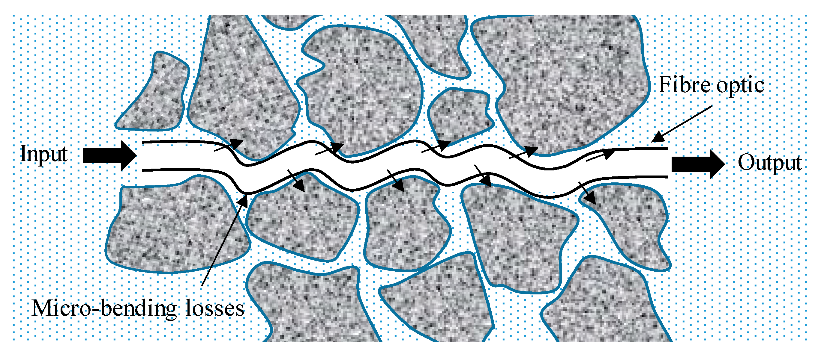
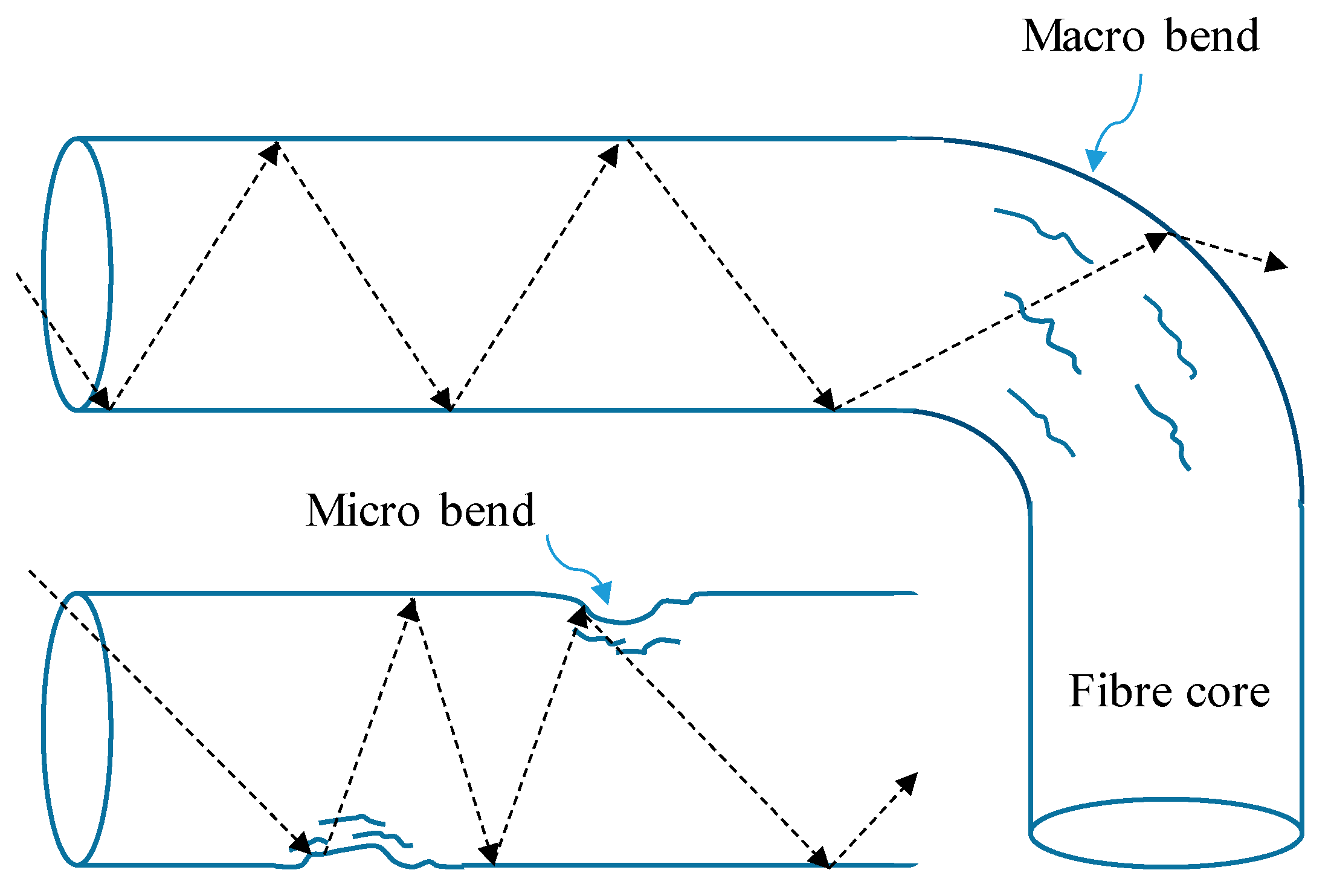
3.1. Characteristics and Principles of Optical Fibres

Fibre optics or optical fibres (OFs) are tiny strands of ⌀~0.2 mm glass [25]. OFs are light-transmitting cylindrical dielectric waveguides consisting of high-purity, low-loss optical materials—most commonly silica, although other plastic and polymer materials are also commercially available [26]. Owing to dopants, the refractive index of the central axis or core (approximately 1.46 for silica) is slightly higher than those of the cladding and the surrounding material [27]. Because internal optical waves moving almost parallel to the axis reach the interface at an angle above that required for total reflection according to Snell’s law, the optical waves remain restricted to the core. However, light escapes when the fibre is bent through a large local radius [28]. A plastic covering (i.e., buffer) protects the OFs from scratches, and numerous OFs are frequently bundled with high-strength fibres such as Kevlar to prepare durable optical cables that can endure industrial handling and applications [29]. Typically, conventional acrylate-protected and nonbuffered OFs exhibit exterior diameters of 250 and 125 µm, respectively [30]. OFs are classified as single- and multi-mode exhibiting core diameters of approximately 10 and 30–100 µm, respectively [31]. Single-mode OFs offer lower optical attenuation because of the smaller difference between the core and cladding refractive indexes, which requires lower dopant concentrations. However, dispersed distinct modes travelling at various velocities distort multi-mode fibre group signals. In multi-mode fibres, the larger core enables easier alignment with the optical sources and connectors, which is highly advantageous for light-guide applications [32]. However, multi-mode fibres may only be used for intensity-based sensing applications. Optical power losses are very small, approximately 0.03 dB/km in multi-mode fibres. However, although OF power losses are irrelevant for sensing applications, 1550 nm is still the preferred window because the required opto-electronic components are more readily available [33].
Various increasingly complex theories have been proposed to explain OF light refraction characteristics. The simplest and most basic model, known as ray optics, posits that light follows the shortest path possible (Fermat’s principle) [34]. Huygens proposed a scalar wave model to express light diffraction [35]. Maxwell explained polarisation by considering light as electromagnetic (vectorial) waves [36]. Quantum optics refers to more complex Schrodinger-equation-based models and determines the energy exchanged between matter and radiation [37,38].

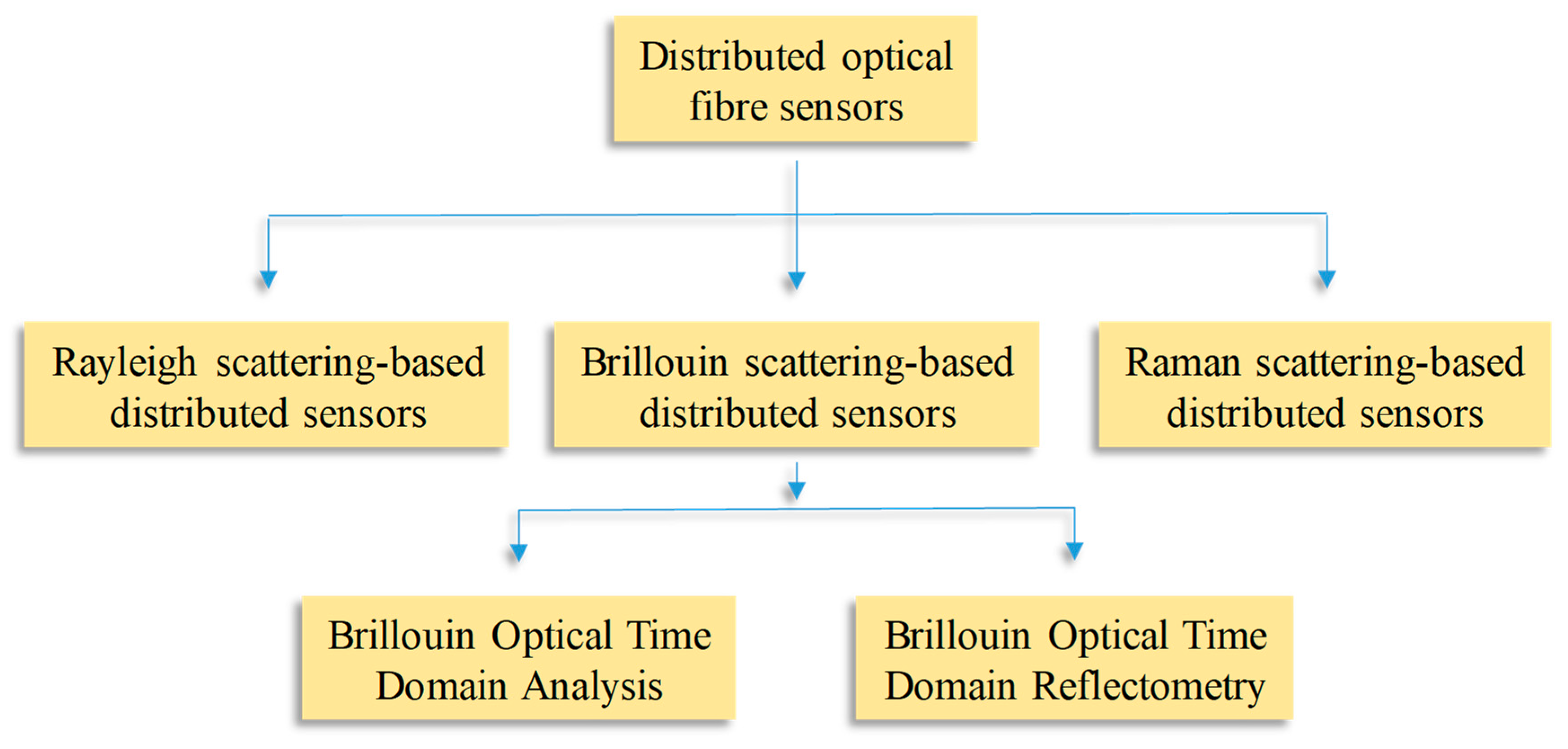
3.2. Types of Fibre-Optic Sensors

The focus of this discussion is mainly on strain, humidity, and temperature measurements—all of which are critical to geotechnical applications [27,39,40,41,42,43]. However, OF sensors are employed in various other applications including electrical fields and chemical sensors for which comprehensive reviews may be found in the literature [44,45,46,47,48]. The benefits of applying OF sensors to geotechnical health monitoring stem from their low weights, small sizes, and non-electrical characteristics—which not only makes them impervious to electromagnetic interference and electrical noise but also enables them to operate with high-voltage electricity in explosive environments, mines, and train tunnels. Furthermore, in addition to topological classifications (e.g., intrinsic, extrinsic, local, or distributed), OF sensors can be fundamentally classified based on the optical parameters impacted by external factors such as phase, intensity, wavelength, and polarisation.

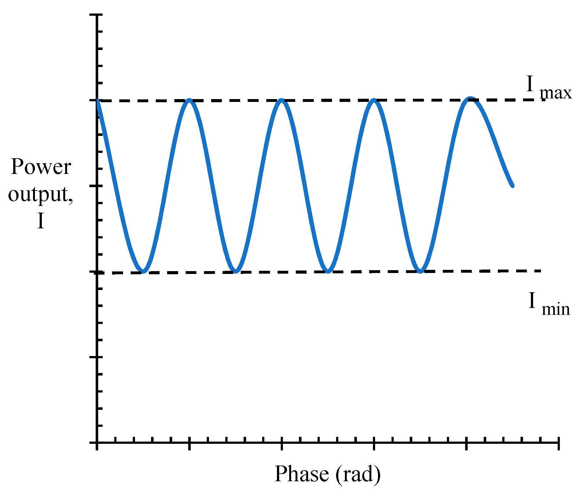
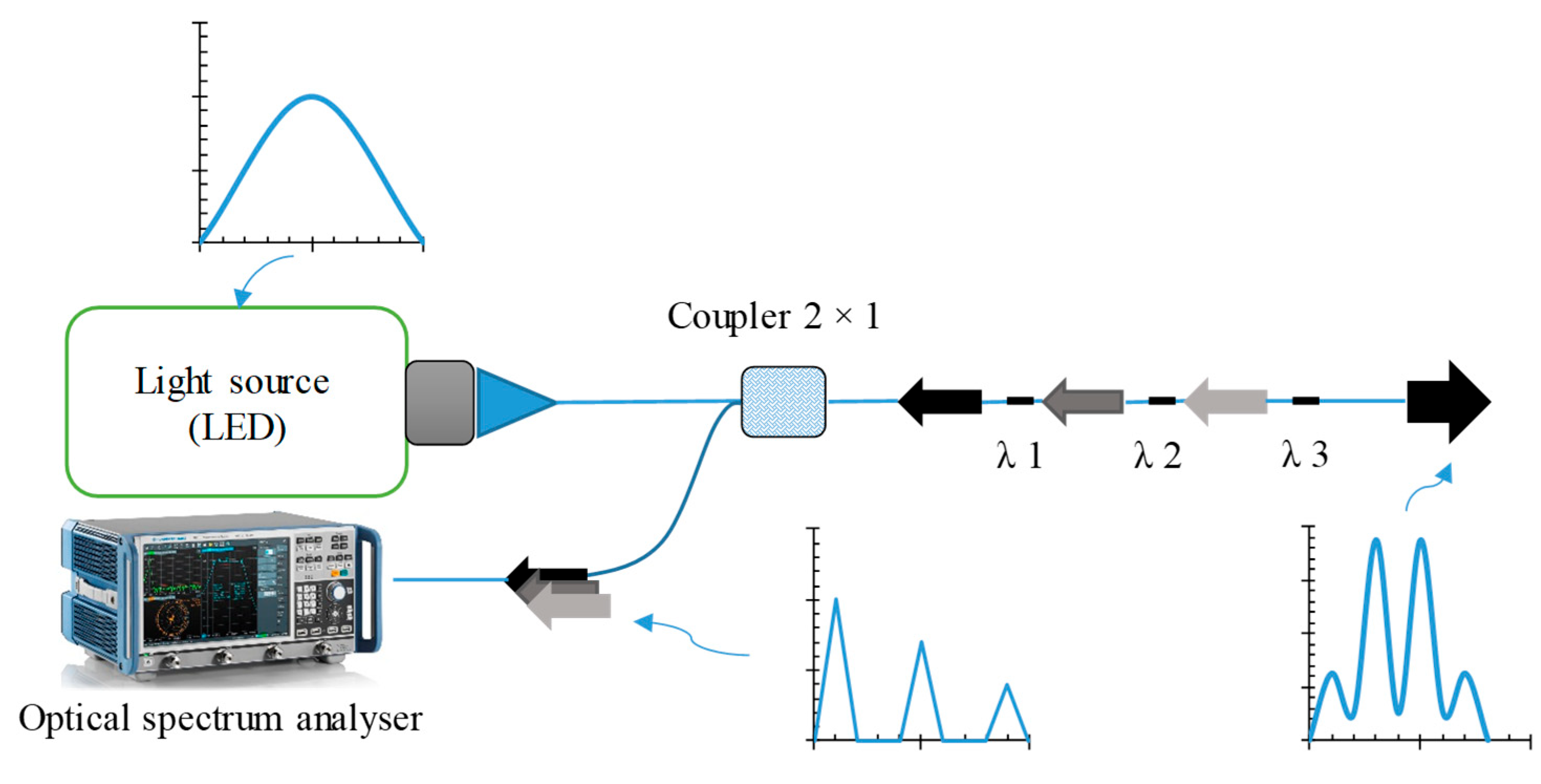
3.2.1. Intensity Sensors

These instruments are the simplest OF sensors and, thus, were the first to be implemented. Moreover, they are still used as proximity and fibre breakage damage detection sensors and to monitor composite material curing and smart geosynthetic and infrastructural health. Intensity sensor devices are composed of an optical fibre—preferably a multi-mode fibre for increased power transmission—a photodetector, and a stable light source, as shown in Figure 3.
According to intensity measurements, although intrinsically micro-bending OF sensors is favourable for monitoring strain and stress in geosynthetics and geotechnical applications (Figure 4), these sensors lose efficiency because of high strains or stresses in coarse angular grains when the sensors are severely bent.
Indeed, the incidence angle of the light in the optical fibre is lower than the critical reflection angle at the core–cladding interface, which causes the light to remain in the optical fibre, except at sharp bends from which the light can escape (Figure 5).
In other words, if the OF sensor is sandwiched between two rough surfaces, applying more pressure causes the OF to bend even more, thereby increasing the optical losses. Although research has previously been conducted based on this concept, it is currently practically abandoned because of violent fluctuations in the light source optical power, calibration challenges, connectors, and temperature effects—all of which worsen system accuracy [26]. However, this effect must be acknowledged, especially in geosynthetics, textiles, and fabric composites wherein roughness-induced micro-bending losses can completely fade out optical signals. Therefore, before attempting to incorporate OFs into geosynthetics (i.e., geotextiles), the fibres must first be protected against micro-bending.

3.2.2. Interferometers or Phase Modulators as of Sensors

Interferometry is one of the most important laboratory techniques for precisely measuring distances. Interferometers have been used to obtain phase information from intensity measurements [26]. A Mach–Zender interferometer schematic is shown in Figure 6.
In this system, a single-frequency monochromatic laser wave is split into two light beams (with either an optical fibre coupler or a conventional optic partial mirror) propagating through routes of different lengths (approximately 380 nm for He–Ne laser red light) before being recombined, which delays one wave relative to the other and leads to oppositely summed electromagnetic fields. Therefore, the output intensity will be zero. As shown in Figure 7, when the length of one of the paths is increased or decreased by half a wavelength, the interferometer signal travels from the input power level to zero. Studies have shown that in highly accurate experiments, even 10 nm changes in the optical path length can be identified. However, because both optical paths are highly sensitive to any disturbance, utilising these OF sensors in field applications remains problematic because changes in the environmental temperature can induce many maximum and minimum drifts [49].
Mach–Zender, Michelson, and Fabry–Perot are three other common traditional OF-based interferometer architectures.

3.2.3. Bragg Gratings or Wavelength-Based Sensors

Fibre Bragg grating (FBG) sensors are intrinsic, multiplexable, local, absolute, and interruption-proof OF-based strain sensors that have attracted considerable attention since their invention in the early 1990s. The main concept is to periodically modulate the fibre core refractive index over a short distance (approximately 1 cm) to act as a collection of weakly uniformly spaced mirrors diffracting the incident light and reflecting the wavelength proportional to the refractive index and spacing. As shown in Figure 8, the Bragg grating behaves as an extremely thin optical filter. When a broadband light pulse is transferred through the fibre, most of the light passes through the FBG except for a specific frequency, which is reflected. The reflected wavelength peak shifts when the temperature is changed or the grating is subjected to a uniform axial strain owing to changes in the refractive index and spacing. These changes can be monitored using an optical spectrum analyser (OSA) and are consequently converted into usable data. Multiple Bragg gratings centred at various wavelengths can be written in the same OF and simultaneously interrogated because commercially available white light sources exhibit an ~40–60 nm wide spectrum and because the maximum strain- or temperature-induced drift is approximately 5 nm [50].
FBG multiplexing is simple to implement. Indeed, because information is encoded in the wavelength, the sensor is extremely resistant to aging, which enables long-term strain measurements without having to recalibrate the device.
Brillouin distributed optical fibre sensors (DOFSs) are also among the wavelength-based OF sensors that have gained considerable attention for application to geotechnical health monitoring in recent decades [50,51,52,53]. Because DOFSs are insensitive to external disturbances, small, corrosion resistant, and lightweight and because DOFSs exhibit fast data collection and low measurement cost, they are advantageous for application to geotechnical health monitoring. However, the high installation cost and complex geosynthetic encapsulation remain some of the leading obstacles to DOFS field applications [54,55,56]. Because DOFSs were initially proposed based on distinct light wavelength effects, they can be categorised as Raman-, Rayleigh-, and Brillouin-scattering-based distributed sensors [57,58,59]. An overview of scattering-based distributed sensors is illustrated in Figure 9.
Figure 10 depicts the primary OF sensors for field applications, including powerful temperature and strain sensors designed and adopted for monitoring tunnelling [60,61].
Polyurethane-sheathed OF sensors offer a lower elastic modulus and, hence, exhibit higher sensitivity toward soil deformation. However, metal-cable-reinforced OF sensors—e.g., glass-fibre-reinforced polymer (GFRP) reinforcers, aluminium pipes, and metal reinforcers—strongly couple with coarse grains and/or rocks, thereby providing more options for field strain, stress, displacement, and temperature sensing. Sun et al. (2014) provided an overview of several encapsulated DOFSs applied to geosynthetics for slope monitoring and considered various material properties [62,63]. Figure 11 illustrates the basic DOFS structures applied to slope monitoring.

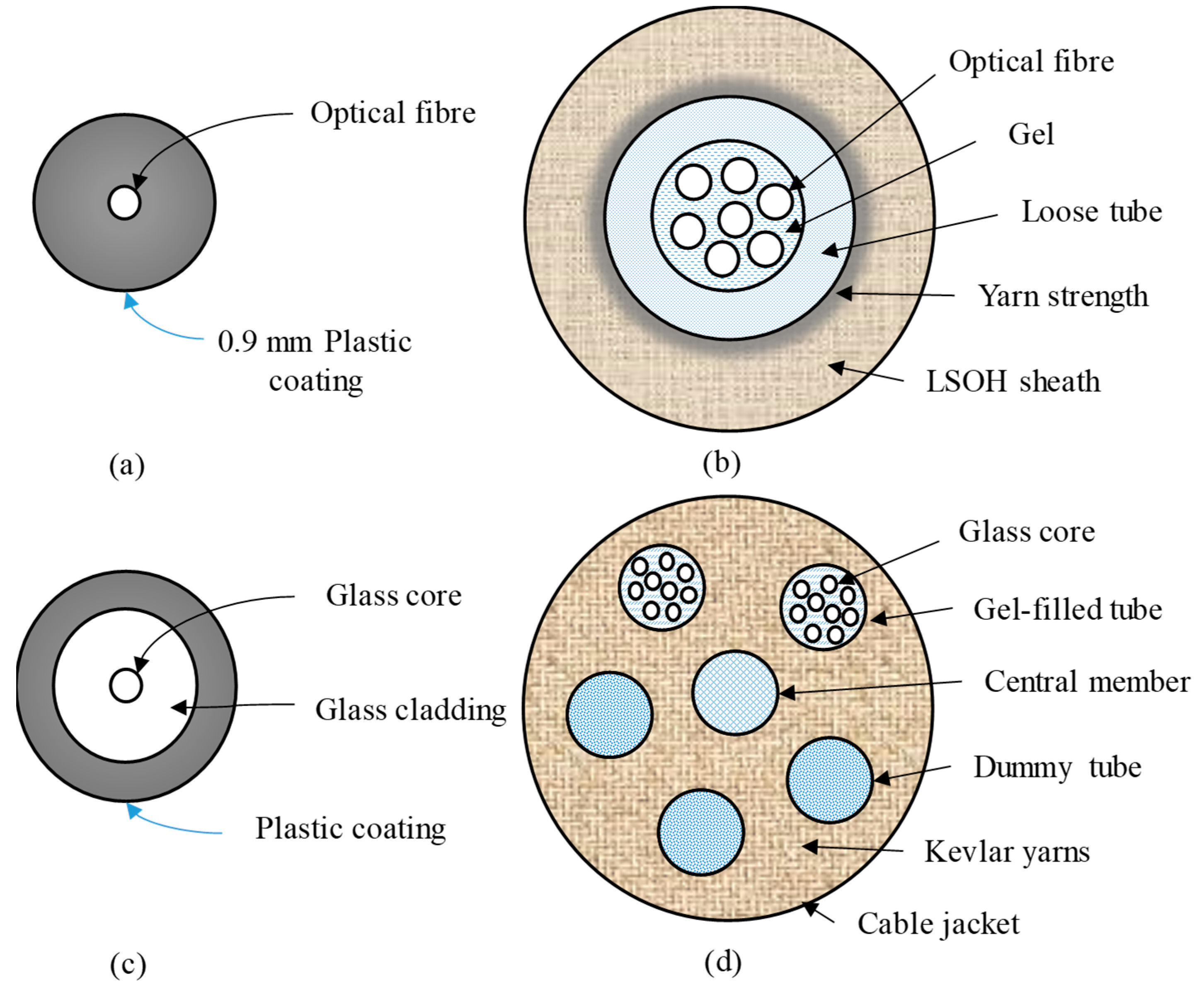
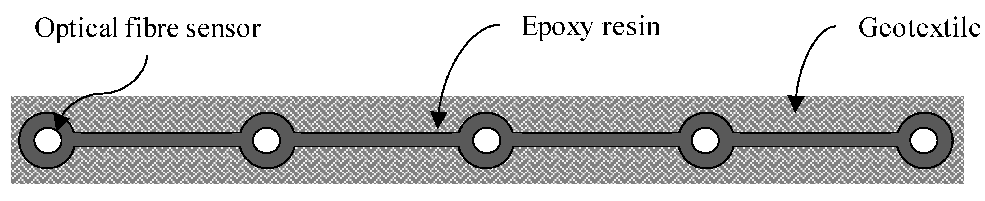
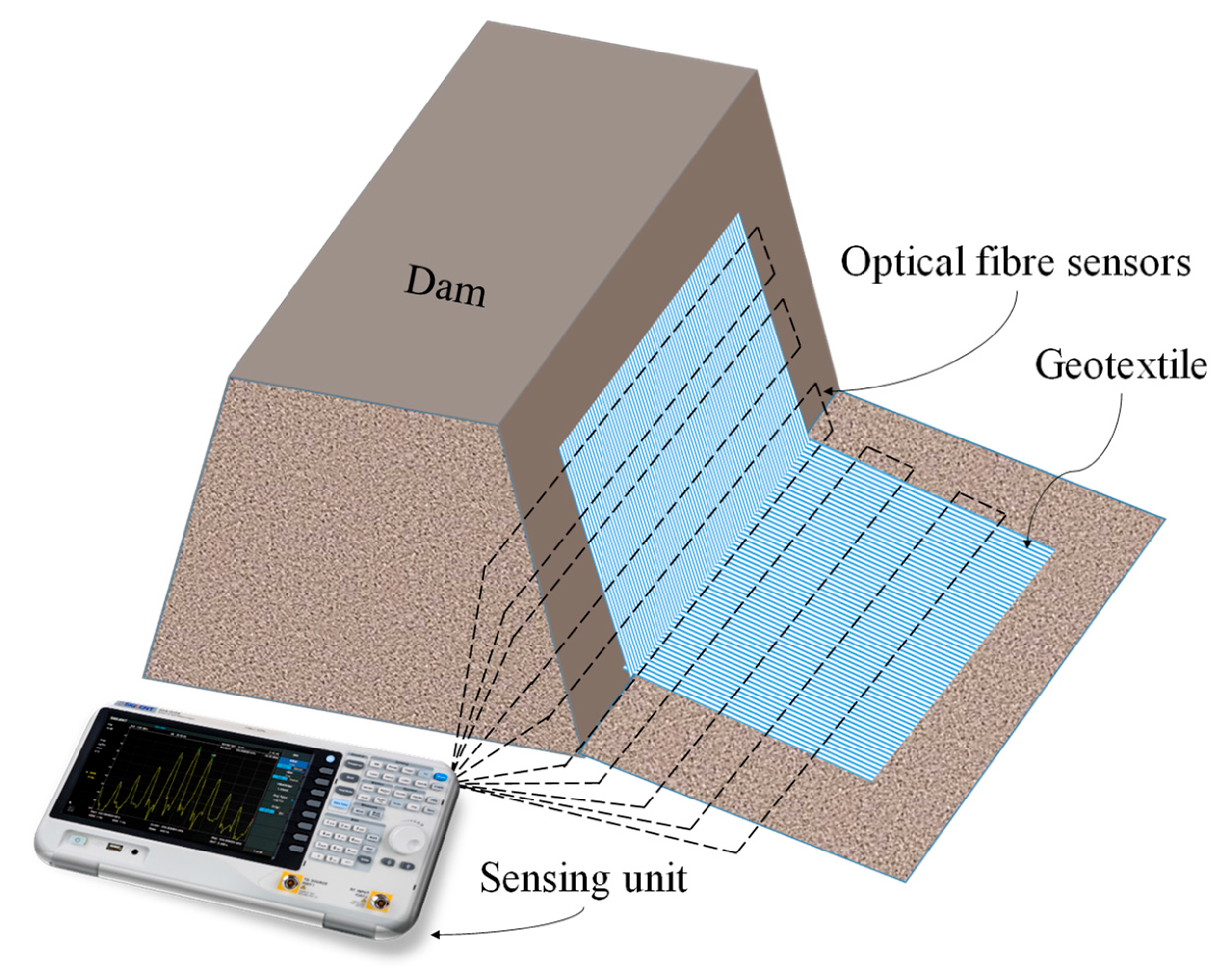
3.3. Production Processes and Applications of Fibre-Optic-Based Geosynthetics

A suitable production or encapsulation method is one of the most important pre-requisites for protecting OF sensors and generating essential coupling between geotechnical structures and sensors [64,65,66]. However, packaging or encapsulation may induce intricate mechanisms for transferring strain and stress from host materials to the OF core [66]. Indeed, comparatively investigating common production and encapsulation techniques elucidates the primary challenges of using OF-based geosynthetics to monitor geotechnical health and the basic perspectives to develop other smart geosynthetics.
Figure 12 illustrates a cross-sectional schematic of a sequence of optical fibres packed into a geotextile wherein OF sensors are incorporated into and adhered to geotextiles using epoxy resin and then coated with another geotextile layer to form a classic “sandwich” structure. This form of packaging can be performed swiftly in the field [67].
A schematic of an OF-sensor-based geosynthetic fabric at a settlement test trench is shown in Figure 13. In this method, a system consisting of multiple OF cables was connected to the sensing fibre chains at both ends of the measurement sensing unit. A large box was separated into two portions to simulate soil settling such that one part could be quickly set up and withdrawn following the test requirements [68,69]. The fabricated OF-sensor-based geosynthetic was implanted between 3 and 20 cm thick sand and gravel–sand composite layers, respectively. This monitoring system is like those used to monitor railway embankments with sensor-equipped geosynthetics [70] and reinforce slopes under surcharge loads with OF-based geogrids [71].
In the latter monitoring investigations, 200 m tight-buffer-covered and 900 m tight-buffer-jacketed OF sensors were encapsulated and fastened to the geosynthetic using epoxy resin.
OF-sensor-based geosynthetics effectively sense strain distributed over long distances and can, thus, be integrated into geomaterials to predict landslides around dams or dikes [70]. A schematic of a typical OF-based geosynthetic monitoring system placed at the landside foot of a dike is shown in Figure 14. To monitor geotextile unidimensional strain fields, distributed OF sensors were utilised, and this method outperformed current landslide monitoring methods. In this system, OF sensors were integrated into a geotextile by a series of warp-knitted fixation positions between the fabric and OF sensors. While the OF sensors are installed into the geotextile, a minimum bending diameter of 10 mm should be avoided to protect the optical fibre sensor from damage in the field. In addition, suitable ⌀3 mm protective coating materials were used for this purpose.
OF sensors can also be incorporated into various fabric elements such as braided bars, fibre-reinforced polymers (FRPs), and glass-fibre-reinforced polymer (GFRP) bars for field applications [72,73,74]. Figure 15a,b show schematics of the OF-sensor-based FRP anchor and GFRP bars, respectively. Although this production and encapsulation method is relatively structurally simple, it includes a complex fabrication process [75,76]. The FRP fibre and OF sensor were first braided together and then fed through pre-drilled holes in a dividing plate. Then, the braided OF and FRPs were impregnated with epoxy and cured at approximately 200 °C.
This smart braided composite worked effectively with the host materials and offered a proper sensing coefficient of approximately 0.050 MHz/µε. Figure 15b depicts the encapsulation method including the pre-stress initially applied to the OF sensors (up to approximately 3000 µε) and the sensors subsequently fastened to the GFRP bars utilising worn metal driving clamps. During the field application, the monitored GFRP bar exhibited a diameter and length of 46 and 30 m, respectively. The extracted strain data were converted to elongation data and were confirmed using a theoretical model published in the literature [77,78].
A summary of OF-sensor-based geosynthetic applications in geotechnical monitoring is listed in Table 2.

4. Self-Sensing Geosynthetics

With the advent and development of smart infrastructures and intelligent cities in recent years, demand has increased for multifunctional elements and materials exhibiting improved mechanical performance while monitoring health and warning about potential risks [90,91,92,93]. Self-diagnosing or self-sensing geosynthetics are multifunctional composites that can sense their own conditions such as strain, stress, deformation, damage, and temperature [94,95,96,97]. In contrast to most smart geosynthetics, self-sensing composites intrinsically exhibit piezoresistivity-based sensing capabilities, which enable more practical, integrated, and real-time infrastructural monitoring [7]. In addition to exhibiting improved mechanical properties and early damage detection capability, self-sensing geosynthetics can provide the information required for instrumenting and managing smart urban infrastructural development such as transportation systems. Self-sensing geosynthetics are composed of conductive phases including various conductive particles and fibres and non-conductive phases or host materials including different polymeric or natural fibres and fabrics [98].
The conductive phase generates conductive paths between the host materials. Owing to percolation and quantum electron tunnelling, several random conductive paths are generated between nano-/micro-particles and/or -fibres [99,100,101,102]. Conductive path electrical resistivity is affected by external factors such as stress, strain, and temperature, which can be detected by measuring the fractional change in the electrical resistivity [103,104,105,106].
Despite the many advantages of self-sensing geosynthetics over other smart geosynthetics, few studies have been conducted to develop applicable self-sensing geosynthetics [92]. However, smart textiles, fabrics, and polymeric filaments developed for monitoring structural components could also be used in geotechnical applications. Hence, recent progress in self-sensing geosynthetics and polymeric elements for applications to geosynthetic components is discussed to provide insight into the evolution of smart geosynthetics.

4.1. Metal-Based Self-Sensing Geosynthetics

Most fillers in this category are metal oxide and metal nano- and micro-particles such as iron, gold, and silver. The characteristics of these nano-materials vary drastically and are vastly different from their bulk counterparts. These nano-particles are semiconductors, making them suitable candidates as sensitive components for applications to different self-sensing geosynthetics.
Tao et al. [105] developed a metal nanoparticle-based polymeric rod sensor from 400 nm gold and 20 nm chromium thin films. Because a polyimide substrate and an easy production method (i.e., magnetron sputtering) were used, the sensor performance metrics—including GF and sensitivity—were also reasonable (4.4–6.9 and 0.0086 Ω/ppm, respectively).
Min et al. [107] described a straightforward method of incorporating non-carbonaceous fillers into a polymer matrix. Different weight fractions of ~100 nm silver nano-particles were dispersed in ethylene glycol solvent and were stabilised by incorporating a polyvinylpyrrolidone (PVP) surfactant. The silver nano-particle suspensions were drop-cast in moulds composed of polyimide tape on a glass slide. The silver films were then annealed for 20 min at 160 °C. Subsequently, a two-part poly-dimethyl siloxane (PDMS) mixture was poured over the annealed silver films and cured for 2 h at 70 °C. The PDMS film thickness was maintained at approximately 0.5 mm. The composite films were then peeled from the glass slides, and the electromechanical activity and morphology were analysed using a universal testing bench and scanning electron microscopy, respectively. Owing to the fabrication approach, PDMS penetrated the voids in the silver film, resulting in strong interfacial locking and void elimination. This also increased the resistance of the deposited silver film. The component sensitivity and GF were affected by both the silver nano-particle concentration and the applied strain. GF also increased owing to increased inter-particle spacing between percolating nano-particles with increasing strain. The authors reported a GF of approximately 109.4 for 130% strain and 0.3 wt.% silver nano-particles. The specimens containing 0.1 wt.% silver nano-particles exhibited an even greater GF, i.e., 268.4 for the maximum strain of 110%. Although the sensor behaviour stabilised after the initial “perturbations” during the normalised resistance cyclic response, the early cycle tests resulted in the emergence of micro-cracks in the silver films, which negatively impacted experimental repeatability.

4.2. Carbon-Black-Based Self-Sensing Geosynthetics

Carbon black (CB, CAS No. 1333-86-4) is prepared by rigorously controlling the thermal decomposition of carbon-rich feeds in an oxygen-depleted (partial combustion) or inert (pyrolysis) atmosphere [108,109,110]. CB is the most cost-effective and industrially manufactured nano-carbon, with an annual output expected to reach 15 Mt by 2025. CB dwarfs the carbon nano-tube (CNT) market (15 kt by 2022), and at 1 USD/kg, it is considerably less expensive than the cheapest grade of CNTs currently available on the market (600 USD/kg) [108].
Cui et al. [5,111,112] investigated the piezoresistivity of conductive-polymer-doped geobelts, which serve not only as reinforcements but also as monitoring devices. The self-sensing geobelt was composed of CB-filled high-density polyethylene (HDPE) and was fabricated for both industrial and laboratory applications. For the laboratory-developed self-sensing geobelt, the optimal CB filler content was 47.5%. For the industrial specimens, the optimal CB concentration was slightly less. The authors also performed tensile and pull-out tests to investigate the mechanical properties and piezoresistivity of the self-sensing geobelt and found that quadratic polynomial and linear functions defined the relationship between the self-sensing geobelt normalised resistance and strain in the ranges 0–10% and 0–7%, respectively. Furthermore, the authors showed that both the tensile strength and elongation at the break of the cyclically loaded self-sensing geobelt both decreased with the increasing number of loading cycles and amplitude compared with the non-loaded self-sensing geobelt. However, the pre-strain only slightly affected the mechanical properties of the self-sensing geobelts. The authors also reported that by increasing the pre-strain and the number and amplitude of the loading cycles, the electrical conductivity of the self-sensing geobelts became more strain sensitive after cyclic loading.
Fathi et al. [113] evaluated the effects of the CB type on the mechanical performance, percolation threshold, and piezoresistivity of low-density polyethylene (LDPE) and polypropylene (PP) composites for application to self-sensing geosynthetics. The CB structure is influenced by the primary CB particle shape, size, and aggregate size. Owing to the higher attractive interactions of the inter-aggregates in smaller primary particles, CB exhibits higher agglomeration and a larger structure. In contrast, when aggregates are composed of only a few primary particles, a smaller CB structure is generated [114]. Owing to the low cost of CB, slightly changing the CB concentration in existing geosynthetic formulations (i.e., 1–4%) is unlikely to markedly impact the geosynthetic manufacturing cost, nor does it necessitate major changes in the manufacturing processes of existing geosynthetic products.
The observations of Fathi et al. [113] supported the theory that the CB percolation threshold concentration was inversely related to the CB structure. Furthermore, their studies showed that composites containing larger CB particles exhibited sharper piezoresistivity. In addition, the piezoresistivity response of PP composites was higher than that of LDPE composites, as listed in Table 3. Regardless of the host polymer utilised, the unitised self-sensing geosynthetic specimens indicated greater gauge factors (GFs) relative to normal commercial strain gauges (i.e., GF = 2).
In the mechanical property characterisation, a CB percentage of up to 20 wt.% reduced the PP composite tensile strength by approximately 50% while leaving the LDPE composite tensile strength virtually intact. The increased PP crystallinity (45–55% for LDPE vs. 70–80% for PP [115]) could explain the more drastic drop in tensile strength. Furthermore, incorporating 30% CB into PP reduces the PP crystallinity by approximately 33% [116]. Indeed, the CB agglomerates and particles break the weak chemical connections and bonding between PP monomers, thereby promoting porosity and amorphous areas in the polymer and reducing the polymer strength [117]. The findings of Fathi et al. also showed that adding a modest CB content to both the PP and LDPE composites markedly reduced the strain at failure.
Recent research on the development of self-sensing geosynthetics has primarily focused on woven and knitted ones. CB-filled PVC is a polymer composite often used to coat woven and knitted geosynthetics. Polyvinyl chloride (PVC) is a low-crystallinity thermoplastic insulating polymer, which means that incorporating even low CB concentrations into the PVC matrix could weaken the composite mechanical performance including the elastic modulus, ductility, and strength. Hence, the CB content should be minimised in PVC composites.
However, to fabricate a conductive PVC composite, a high CB concentration (i.e., 5 wt.%) is typically required. These opposing requirements should be met simultaneously through a well-controlled manufacturing process that includes proper mixing, moulding, and curing stages. In PVC-coated PET yarn self-sensing geosynthetics, the inner woven PET yarns are the load-bearing components; thus, any high-CB-concentration-induced changes in the coating tensile strength will not unfavourably affect the mechanical properties of the self-sensing geosynthetic product. However, the composite must be coated to maintain its structural integrity and shield the PET from negative environmental influences and installation damage (i.e., electrical interference from wet soils and corrosive and other bio-active materials such as acids, aqueous salt solutions, and alkalis).
The mechanical properties and piezoresistivity of CB-filled PVC composites were first investigated by Hatami et al. [118] for the potential application of the composites to the production of self-sensing geosynthetics. To prepare PVC/PET self-sensing geosynthetics, the authors mixed regulated concentrations of powdered low- and moderate-structured CBs with plasticised PVC. The in-isolation strain sensitivity was adequate for both CB-filled composites, indicating that they could be used in field applications. Nevertheless, low-structured carbon black PVC composites such as LDPE and PP [113] exhibited increased piezoresistivity responses because the conducting networks were more prone to discontinuities and rupturing under tensile loads.
These investigations focused on the strain conductivity of self-sensing geosynthetic materials subjected to monotonic loading. Geosynthetics are also widely employed to stabilise various earthwork structures subjected to time-dependent loads (i.e., traffic). Time-dependent loading can irreversibly change the strain and electrical conductivity in CB-formed conductive networks in self-sensing geosynthetics. To investigate the effect of cyclic loading on the piezoresistivity of CB/PVC composites, Yazdani et al. [119] employed the identical CBs used by Hatami et al. [118] and examined how the strain magnitude, loading rate, stress relaxation, and pre-straining influenced the cyclic loading performance of the CB/PVC composites. Their results showed that the conductive network in coated components composed of higher-structured CB exhibited more resilient piezoresistivity and suffered less damage during cyclic loadings. In addition, the strain sensitivity of the coated specimens was also increased using pre-strain. The ratio of the initial peak strain to the subsequent operating peak strain was also used to determine the degree of pre-straining applied to the samples. However, the composite piezoresistivity was more consistent and steadier when the ratio was higher.
These studies on self-sensing geosynthetics primarily investigated the performance of unitised and coated yarn-based self-sensing geosynthetic prototypes in isolation. However, in field applications, the soil-confining pressure is expected to affect the piezoresistivity of self-sensing geosynthetics. Yazdani et al. [120] employed a modified direct shear test set up to evaluate the effect of confining pressure on the piezoresistivity of a PVC-coated PET-yarn-based self-sensing geosynthetic. They conducted in-soil tensile experiments at 10, 30, and 50 kPa confining pressures to mimic the upper levels of reinforced soil structures subjected to greater strain and deformations [121] and reported that the piezoresistivity response of self-sensing geosynthetics was reduced by increasing the confining pressures and strain rates. However, the amplitude and repeatability of the piezoresistivity responses recorded in the in-soil experiments were deemed adequate for civil engineering applications.

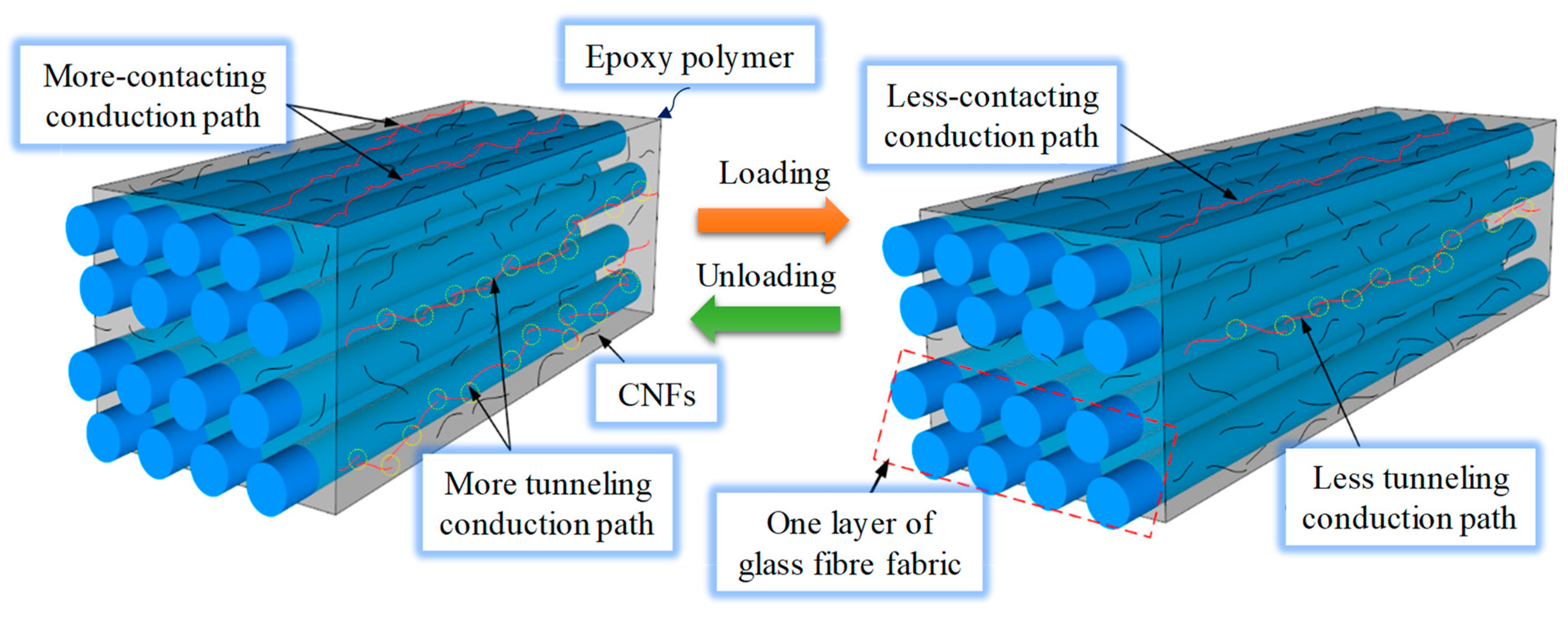
4.3. Carbon-Nano-Tube-Based Self-Sensing Geosynthetics

Due to the continuous and considerable decline in the carbon nano-tube (CNT) price from approximately 1,500,000 USD/kg in 1999 to the current retail price in the range 50–300 USD/kg [122], the research and development of self-sensing geosynthetics has recently found new potential and prospects. Owing to their highly desirable properties such as high flexibility, high aspect (i.e., length-to-diameter) ratio, high specific surface area, low density, and remarkable mechanical and electrical characteristics, CNTs are increasingly utilised in nano-composites. Hatami et al. [8] incorporated a specific CNT concentration into HDPE and PP to prepare piezoresistive and UV-protected geosynthetic prototypes and compared their performances with those of geosynthetic-containing CB. Their results indicated that the CB-filled specimens exhibited a marked piezoresistivity response compared with the CNT-filled PP composites. Table 4 lists the mean GFs of the composites tested by Hatami et al. [8]. The greater piezoresistivity response and sensitivity of the CB-containing specimens were attributed to the grape-bunch-like CB fillers, which formed a less entangled network and, consequently, resulted in higher piezoresistivity than the needle-shaped CNTs under tensile strain.
Hatami et al. [8] demonstrated that self-sensing geosynthetic technology could lead to a more cost-effective and dependable alternative to currently available strain sensors (i.e., gauges).
However, the application of CNTs to self-sensing geosynthetics remains problematic because CNTs do not suitably disperse in polymers. Although “dispersion” usually refers to uniformly distributed individual fillers in the host matrix, the term must be re-defined for fillers such as CNTs, which intrinsically thermodynamically physically agglomerate with neighbouring tubules to form aggregated bundle morphologies. Each bundle contains hundreds of closely packed CNTs held together by van der Waals attraction energies of approximately 500 eV/m per CNT–CNT [123]. This entanglement and agglomeration is particularly important in CNTs owing to their flexibility and high aspect ratio [124]. Indeed, enhancing CNT dispersion in a polymer composite would necessitate a trade-off between the composite mechanical and electrical properties. Usually, complete dispersion leads to smaller bundles and, as a result, smaller stress concentration zones, which could affect the mechanical performance, weight, and manufacturability of the polymeric matrix [125]. However, bundling and agglomeration both reduce the percolation threshold [126].
Because of the effectiveness and importance of both the electrical and mechanical properties of self-sensing geosynthetics (particularly unitised self-sensing geosynthetics), an optimal mixing and fabrication technique must be devised to produce the desired level of CNT bundling. Hence, determining effective dispersion strategies and evaluating the resulting dispersion quality are critical steps in designing CNT–polymer composites. The effects of processing conditions and dispersion quality on the mechanical and electrical performances of PVC composites containing multi-walled CNTs were evaluated by Yazdani et al. [127,128] for application to self-sensing geosynthetics and other applications involving electrically conductive polymer composites. The authors investigated the mechanical properties and electrical conductivity of specimens prepared using various mixing methods and quantified the specimen subsurface dispersion using an approach devised by Smith et al. [129].
Their results revealed that specimens exhibiting superior dispersion also exhibited higher ultimate failure strain and strength, whereas specimens exhibiting poor dispersion also exhibited higher elastic moduli.
The mechanical properties and piezoresistivity of tensile-loaded MWCNT-reinforced PVC composites were also investigated by Yazdani et al. [130]. They showed that incorporating 0.5 wt.% MWCNTs into the PVC composite increased the tensile modulus fivefold and considerably reduced the failure strain while leaving the ultimate strength nearly unchanged. They also reported that MWCNT-containing PVC-based self-sensing geosynthetics exhibited higher GFs compared with standard foil strain gauges and conventional metals, indicating that MWCNT-containing PVC-based self-sensing geosynthetics have great potential for application to damage detection and infrastructural performance monitoring.
Notably, geosynthetics are typically installed at such depths in civil engineering applications that the geosynthetic temperature does not change appreciably throughout the service lifetime. Hence, the temperature will likely not affect the strain sensitivity of self-sensing geosynthetic devices in typical applications.

4.4. Graphene-Based Self-Sensing Geosynthetics

Graphene is a two-dimensional (2D) sheet exhibiting six-member rings organised in a honeycomb pattern. Graphene is the strongest, most flexible, and thinnest substance [131]. Owing to its unique molecular structure, graphene exhibits several extraordinary mechanical, electrical, and chemical properties including elasticity, substantial flexibility, and the ability to connect with numerous surfaces [132]. Graphene is harder and stronger than other well-known materials, and mono-layer graphene exhibits an elastic modulus and a tensile strength of approximately 1.1 TPa and 125 GPa, respectively [133]. In graphene, π electrons move at 1/1300 the velocity of light [134]. Moreover, the graphene electrical strength is negligibly influenced by electron interference.
In addition, the graphene electrical conductivity is 60 times higher than that of single-walled carbon nano-tubes (SWCNTs) [135]. Furthermore, graphene conductivity remains constant over a wide temperature range, which is critical for reliability in a wide range of applications. Although the wide conductivity range provides graphene with outstanding electrical characteristics, the (theoretical) specific surface area is approximately twice as large as the CNT one, that is, 2630 and 1315 m2/g for graphene and CNTs, respectively. Consequently, graphene has attracted considerable attention in different research fields particularly owing to its exceptional characteristics.
Graphene-based self-sensing geosynthetics offer remarkable advantages such as low cost, high flexibility, light weight, and easy synthesis. Moreover, the composite sensitivity may be further enhanced by optimising the synthesis method and doping with an appropriate graphene concentration [136]. A summary of various graphene-based polymers for application to self-sensing geosynthetics is listed in Table 5.

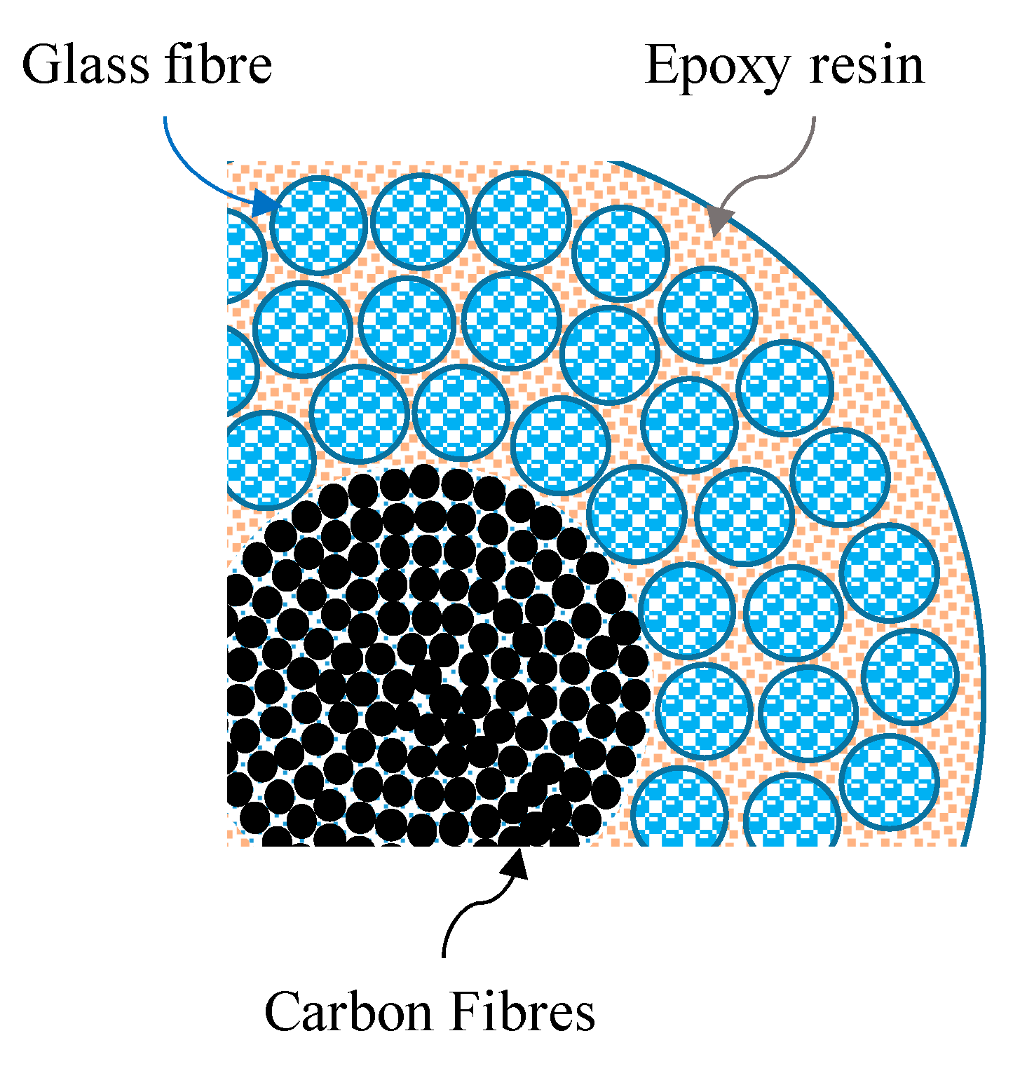
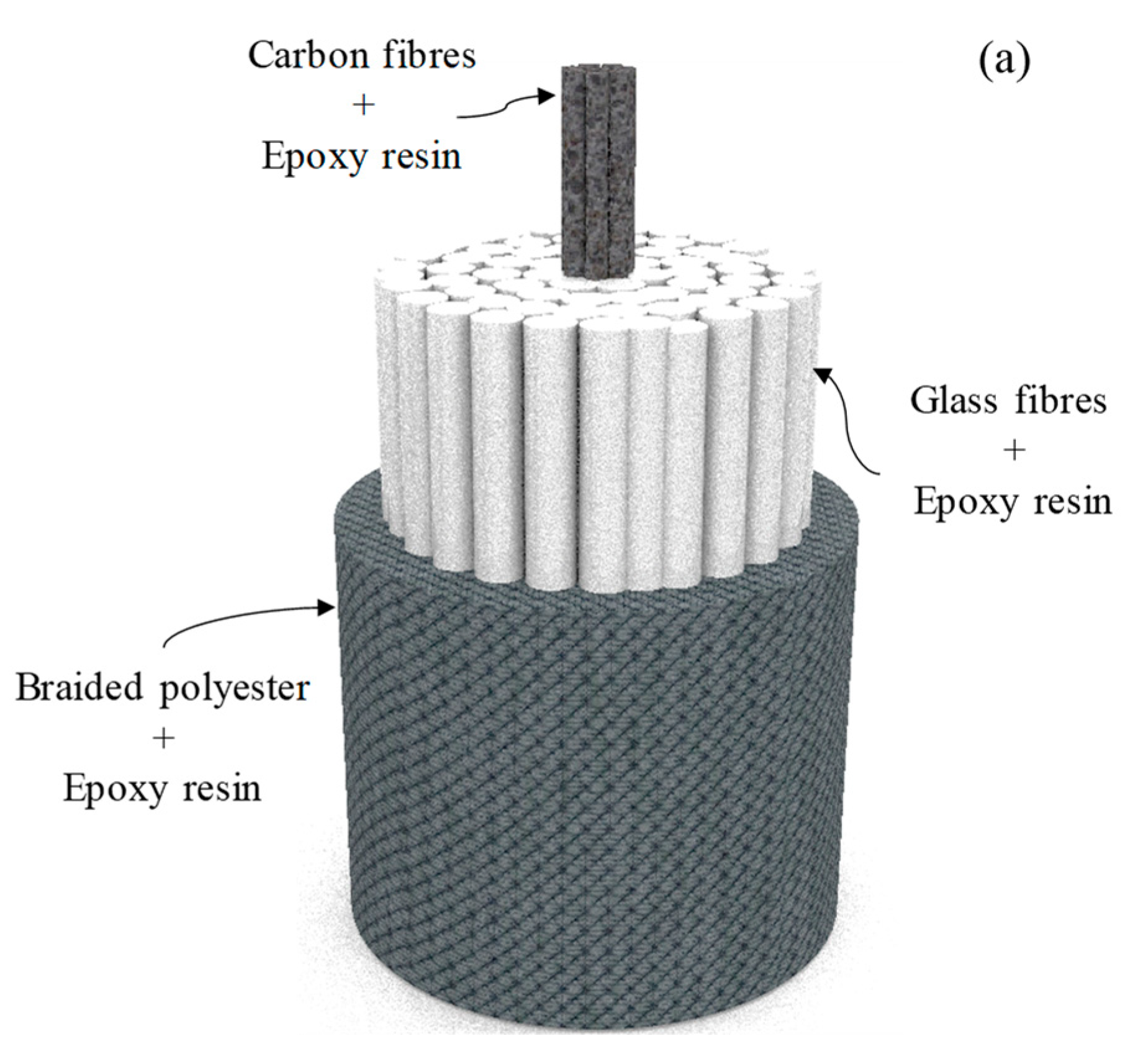
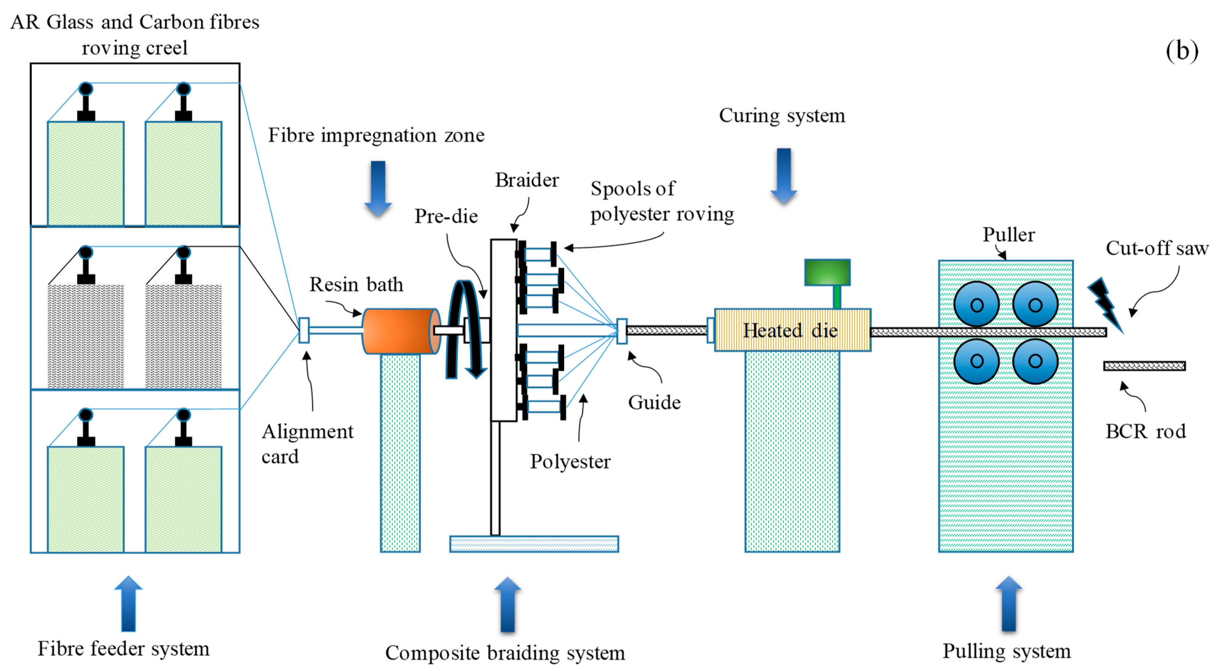
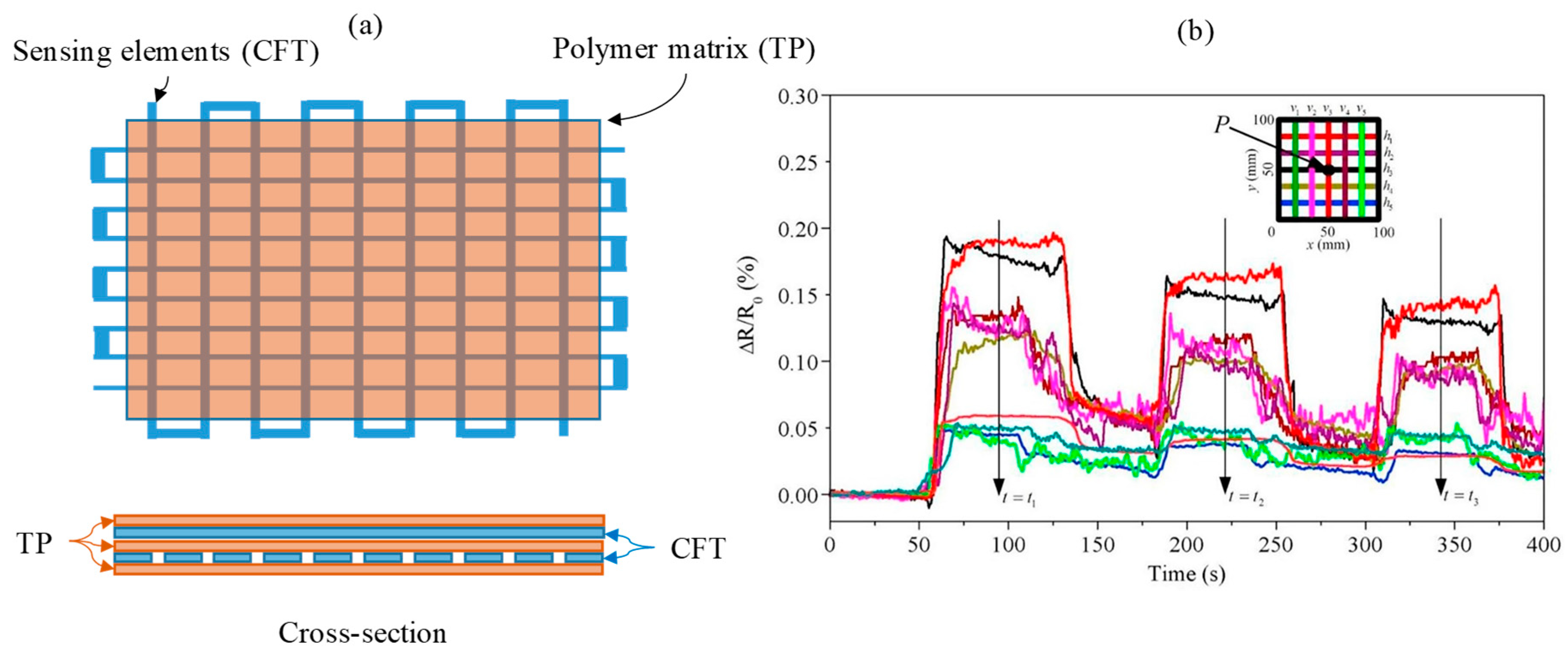
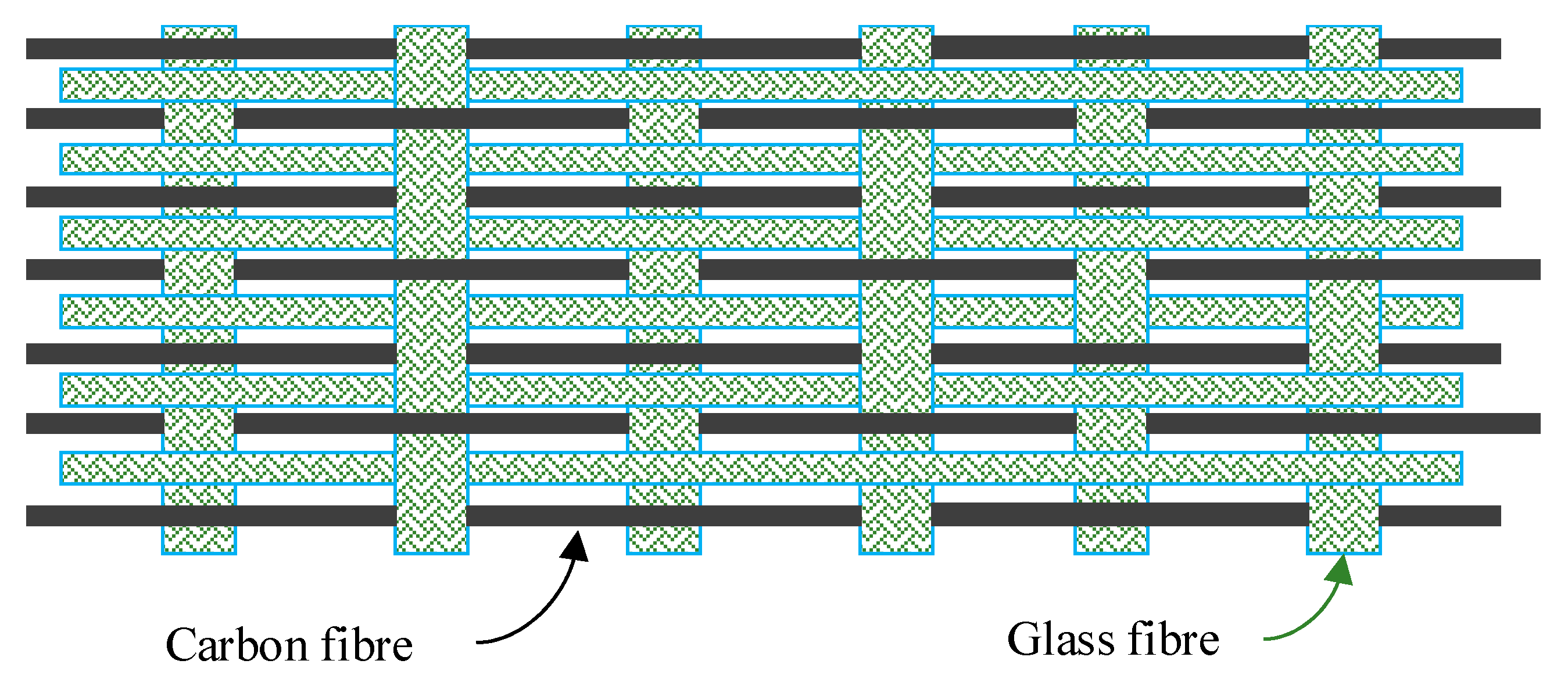
4.5. Carbon-Fibre-Based Self-Sensing Geosynthetics

Various carbon fibres (CFs) such as continuous carbon fibres, carbon short fibres, carbon micro-fibres, and carbon nano-fibres (CNFs) are widely used as a conductive phase in self-sensing geosynthetics. Indeed, CFs have also been braided or distributed in polymer and fabric composites to develop self-sensing geosynthetics. Continuous carbon fibre polymer composites are fabricated by combining various carbon fibre arrangements such as textile or unidirectional knitted or woven tows with polymer resin under controlled conditions [144].
These composites exhibit complex features including low density, high stiffness and strength, high damping dispersion energy, strong impact and corrosion resistance, and tuneable thermal expansion [145]. In addition, hybrid or multiple carbon and inorganic fibre composites (e.g., aramid, polypropylene, and glass) have been developed to improve the composite sensing capability and strength [146,147,148].
The composite structural element configurations determine the strain-sensing capability and attributes of continuous carbon fibre polymer composites [149,150,151,152]. The strain sensitivity of continuous unidirectional carbon-fibre-reinforced epoxy composites has been reported in the fibre direction. The tensile force reversibly decreases the longitudinal electrical resistance, whereas strain increases the transverse electrical resistance because changes in the fibre alignment change the electrical connections of continuous carbon fibres. When a tensile load is applied to the composite, the fibres align more in the loading direction, thereby potentially increasing the electrical connections and reducing the resistance [152,153]. However, further increasing the tensile loading reduces the fibre cross-sectional area and consequently increases the electrical resistance. Continuous carbon fibre polymer composites could exhibit GFs ranging from −35.7 to −37.6 and from +34.2 to +48.7 in the longitudinal and transverse directions, respectively. Consequently, continuous carbon fibre polymer composites could be very useful for developing sensing applications and self-sensing geosynthetic geomaterials and for building and maintaining civil infrastructure, particularly railway foundations. However, carbon fibre polymer composites usually exhibit low ductility. Consequently, multiple or continuous carbon fibre/epoxy hybrid composites have been investigated with other materials to enhance the self-sensing and mechanical properties [154,155]. The fibre characteristics, constituent fibre proportion, and composite fibre organisation all impact the composite ductility and sensitivity.
Glass fibres, one of the most common fibres, have piqued the interest of researchers to produce hybrid CF/GF polymer composites exhibiting improved ductility and sensitivity [156,157]. These composites exhibit an internal carbon fibre core externally covered by a glass fibre bundle, as shown in Figure 16.
Nanni et al. also reported proper sensing capability and piezoresistivity for this composite under cyclic and monotonic tensile loading [156,158]. By increasing the CF content, an alarm signal was achieved practically at the failure load (2.4% CF and 49% GF). They also reported drastically increased electrical resistance at loads much lower than the failure load when the CF content was reduced (48% GF and 0.2% CF; 48% GF and 0.6% CF) [156,158]. However, the hybrid CF/GF epoxy composites could not identify early damage because the fractional changes in the electrical resistance were approximately 1% at strains below 0.6%. Indeed, low strains could only be properly detected in CF/glass fibre composites by computing the residual resistance under pre-stress conditions [159,160]. Braided composite rods (BCRs) are another continuous carbon fibre polymer for developing smart geosynthetics and have exhibited excellent low-strain sensitivity [161,162,163,164]. In BCRs, a CF and glass fibre mixture was treated with polymer resin and was axially over-braided with polyester filaments. The freshly braided structures were subsequently cured to manufacture the composite rods.
By adjusting the polyester filament braiding tension and velocity, a certain degree of misalignment can be introduced to the axial CF, thereby changing the electrical contacts and, as a result, markedly changing the low-strain electrical resistance. The BCR strain-sensing capabilities were improved by reducing the composite CF content, and the maximum GF of approximately 24 was obtained at a flexural strain of 0.5%. The BCR cross-section and manufacturing process are illustrated in Figure 17.
Recent developments in manufacturing technologies have enabled functional and complex polymer composites to be rapidly and cost-effectively produced. Fused deposition modelling (FDM) is one of the most conventional manufacturing processes, which has currently attracted the attention of many researchers owing to its potential applicability, ease of use, and low cost [165,166]. Luan et al. used FDM-based 3D printing to develop a continuous carbon fibre polymer composite and subsequently detect and recognise stress and damage locations [167]. Figure 18 clearly shows a continuous carbon fibre tow (CFT) grid and a thermoplastic (TP) matrix were automatically printed using a double-nozzle FDM printer. In this smart composite, the location of the applied stress and the resulting strain were deduced according to the maximum fractional change in the CF tow electrical resistance, as shown in Figure 18b.
Non-polymeric continuous carbon fibre composites are also suitable for developing self-sensing geosynthetics owing to their consolidation capabilities and increased interactions. However, the lack of a polymer reinforcement increases the effects of moisture on their sensing capability, thereby rendering this composite more prone to environmental factors. Goldfeld et al. [168] developed a non-polymeric hybrid continuous carbon and glass fibre fabric (Figure 19) for application to moisture and damage sensing. The fabric produced an electromechanical sensing GF of approximately 1 and used the Wheatstone bridge to detect a humid environment by fractional variations of approximately 10−5 in the electrical resistance.
Currently, micro- and nano-CFs have attracted attention to enhance polymer component sensitivity for application to self-sensing geosynthetics. Indeed, conductive nano- and micro-paths formed by carbon nano- and micro-fibres are sensitive to external factors including low stress, strain, deformation, humidity, and temperature.
Zhang et al. [7] used 3D printing to develop an integrated piezoresistive geobelt wherein conductive acrylonitrile butadiene styrene (ABS) containing ⌀7 lm × ~10 lm long CF powder was directly embedded into non-conductive polylactic acid (PLA) to fabricate a conductive wire. The geobelt stress and deformation could be determined because the conductive wire resistance increased with decreasing wire cross-sectional area. The integrated resistance geobelt eliminated sensor contact with external humidity, which could otherwise lead to sensor failure and erroneous test results. To increase the sensing efficiency, the authors recommended that the wires be oriented in the tension stress direction. They also stated that although increasing the number of conductive wire layouts may somewhat reduce the self-sensing geobelt tensile strength, it considerably improved the changes in the electrical resistance rate under pressure or tension, which more precisely reflected the strain. Hence, the number of longitudinal conducting wires could be accordingly increased with increasing geogrid width and size.
Moreover, the authors also used a parabolic function to fit the relationship between the stress and the resistance at both ends of the grid. Based on the experimental results, the test ranges of the 3D-printed self-sensing geobelt were approximately 2.1–10% of the effective geobelt length.
Wang et al. [169] dispersed 0.5, 1.0, 1.5, 2.0, and 3.0 wt.% CNFs in epoxy resin and then infused the composites into glass fibre fabric to produce CNF/glass-fibre-reinforced polymer laminates for application to geomembranes (Figure 20). The authors measured the fractional change in the electrical resistance under constant- and incremental-amplitude cyclic and monotonic tensile loadings.
According to the classical power law, a percolation threshold of approximately 0.86 wt.% was achieved using the optimal CNF concentration. Furthermore, proper piezoresistivity was also achieved under monotonic tensile loading until the final failure. The authors categorised the fractional changes in the electrical resistivity according to different main phase damage mechanisms including matrix micro-cracking, transverse cracking, debonding, longitudinal splitting, breakage, and fibre delamination.

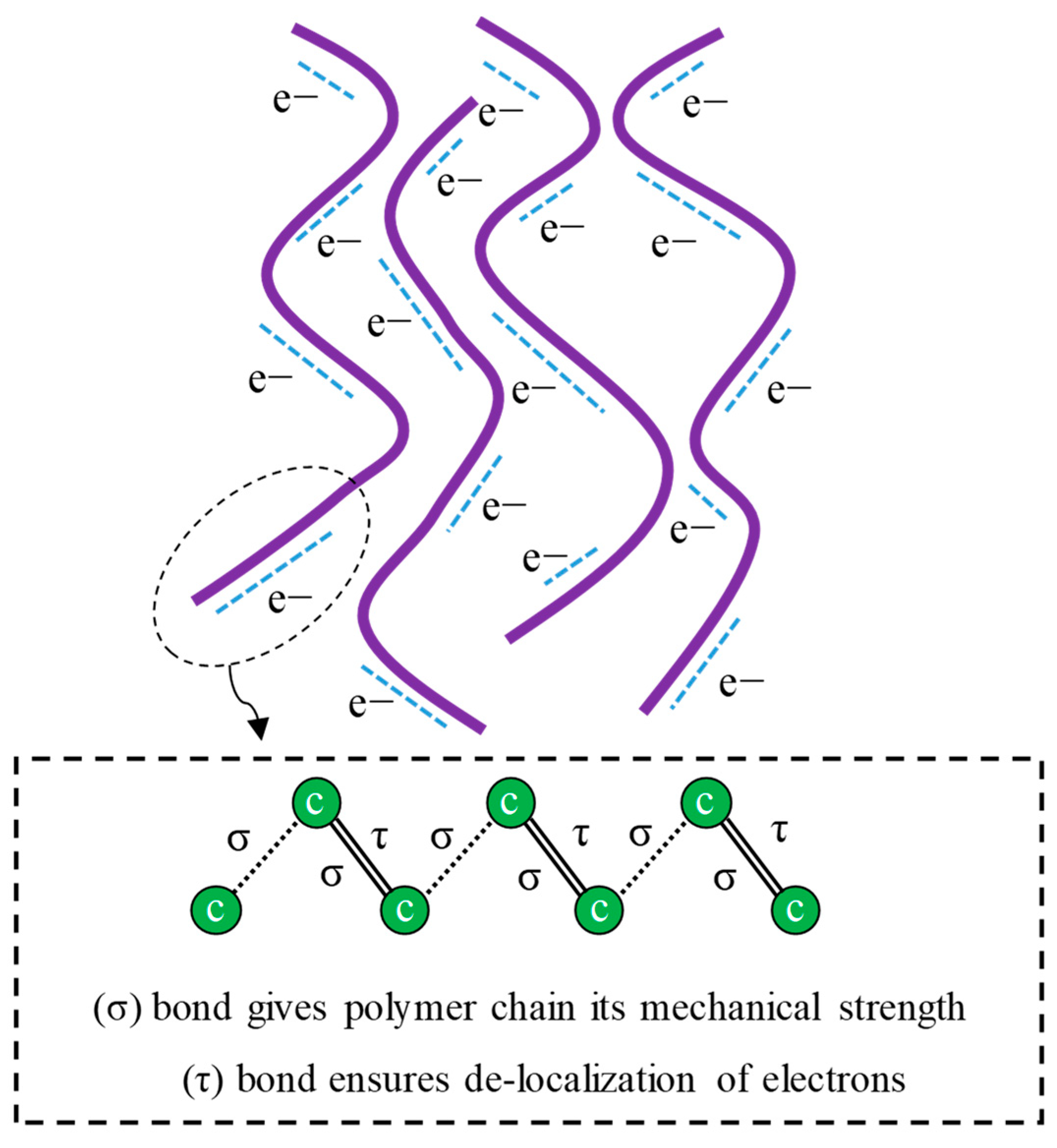
4.6. Intrinsically Conductive-Polymer-Based Geosynthetics

Intrinsically conductive polymers are π-conjugated systems, meaning they feature alternating single and double bonds in their chemical structures [170,171,172]. The backbone of these polymers is composed of sp2-hybridised carbon atoms. Consequently, one valence electron resides in the pz orbital orthogonal to the three sigma bonds. Therefore, the valence electrons are delocalised and exhibit high mobility. Indeed, in intrinsically conductive polymers, this mobility is a charge transport mechanism. However, to enhance the polymer conductivity and charge transfer, the structure must be disrupted by doping to either add or remove an electron [173].
Doping changes polymer conductivity from insulating to metallic [174] by either extracting electrons from the valence band highest occupied molecular orbital (HOMO)—i.e., oxidation—or moving electrons to the conduction band lowest unoccupied molecular orbital (LUMO)—i.e., reduction. To establish a positive molecular charge, the polymer backbone can be treated with electron-deficient species. Owing to hole formation, the polymer chain is converted to p-type, and electron removal from the main chain is known as p-doping or oxidation [175]. Alternatively, to induce a negative molecular charge, the polymer backbone can be improved with electron-rich species. Adding electrons is known as reduction or n-doping [175], and the electrons convert the polymer chain to n-type.
Both n- and p-doping markedly boost conjugated polymer conductivity, which is determined by the dopant characteristics and concentration and the doping time. Dopants may include smaller cations and anions such as Na+, Cl, and ClO−4 and large polymeric species such as polystyrene and polyvinyl sulfonates. Owing to their high conductivities, doped intrinsically conductive polymers are suitable for various smart geosynthetics and electronics applications. However, their relatively high production cost should be considered. The intrinsically conductive polymer structure and charge transport mechanism due to delocalised π electrons are illustrated in Figure 21.
Moreover, dopant properties considerably impact conductive polymer characteristics. Large dopant molecules can change the polymer physical properties and surface topography and increase the polymer density. Furthermore, large dopant molecules strongly attach to conjugated polymers and are more difficult to leach than smaller dopant molecules, which may easily leach. Therefore, small dopant molecules are suitable for applications requiring rapid detachment and attachment [176]. Consequently, sensitivity to environmental ionic species increases with decreasing dopant molecular size. Furthermore, the dopant molecular size affects the doped polymer solubility. For example, with increasing dopant chain length, polyaniline (PANI) solubility increases, thereby facilitating solution processing [177]. However, increasing the dopant chain length by increasing the d-spacing and inter-chain separation reduces the polymer crystallinity. Moreover, the polymer conductivity increased with increasing dopant concentration until saturation. Finally, because doping is a reversible physical process, it can be followed by de-doping to revert to the original polymer exhibiting all its original characteristics.
In these polymers, temperature and conductivity are inextricably linked. In addition, highly doped polymers are less vulnerable to temperature-induced conductivity changes than less-doped polymers [178]. Reversible doping/de-doping and the polymer conductivity dependence on concentration, temperature, and dopant molecular size have all been used to design sensitive components for sensing stress and various chemical species and for electrochemical capacitors, electrochromic displays, energy devices, and smart windows [170,179].
Poly 3,4-ethylenedioxythiophene (PEDOT) is an intrinsically conductive polymer that has a wide range of applications [180]. Losaria et al. [181] developed a stretchable sensor made of PEDOT dispersed in a thermoplastic polyurethane (TPU) host matrix and compared the performances of FeCl3 and fluoroalkylsilane (FTS) dopants. Although increasing the dopant concentration diminished the polymer elasticity, the plasticity mitigated the FTS-induced polymer stiffening. Therefore, FTS was eventually chosen to fabricate very stretchable (above 300%) and durable (more than 100 cycles) strain sensors exhibiting a proper GF (approximately 10 at 100% strain). Lu et al. [182] used poly (2-acrylamido-2-methyl-1-propane sulfonic acid (PAAMPSA), phytic acid (PA), and PANI to develop a strain sensor laminate wherein PA serves as a cyclic protonic acid, PANI is an inherently conductive polymer, and PAAMPSA is an ionic polyelectrolyte. In addition, PA reportedly forms cationic complexes. Because of their suitable characteristics, PAAPMSA and PA were employed as a PANI dopant and cross-linker, respectively.
The strain sensor components were fabricated using a soft, flexible membrane and reportedly exhibited extremely high stretchability, bending, and longitudinal strain sensitivity. Moreover, the strain sensor reportedly exhibited repeated self-healing owing to electrostatic interactions and considerable hydrogen bonding in the polymer complex, which also provided the exceptional stretchability. By constructing reduced (GO)- and PA-based nano-rod arrays on fabric substrates, Zheng et al. [183] developed a textile-based flexible stress sensor exhibiting a linear response over a wide stress range (0.0005–40 kPa) and pressures as low as 0.5 Pa. Similarly, nano-rods consecutively assembled on the textile offered a GF of −78 when utilised as strain sensors. In addition, the sensitive components exhibited remarkable cycling durability, with 1000 and 11,000 cycles reported for the strain and pressure sensors, respectively.

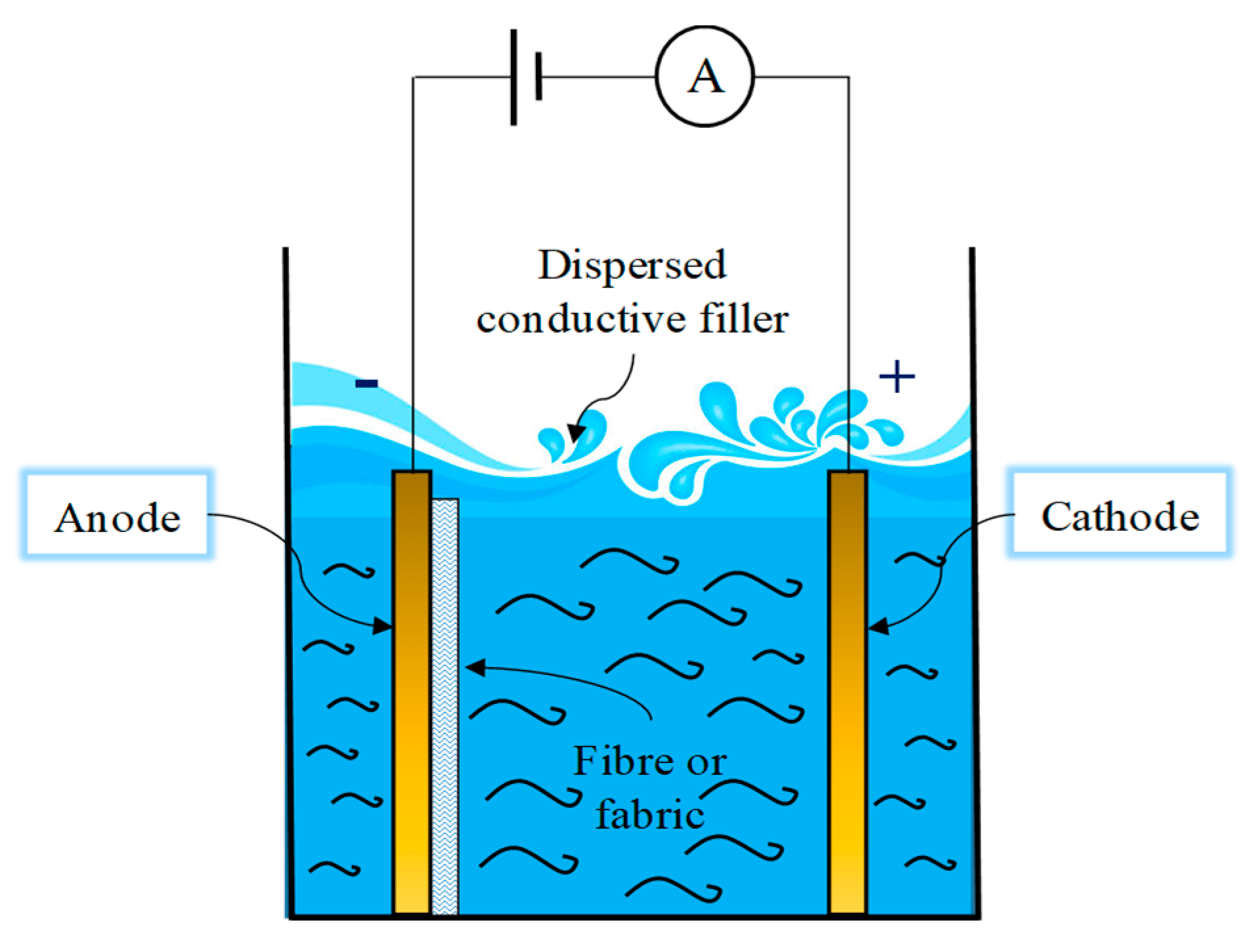
4.7. Geosynthetic Production and Fabrication Processes

Owing to the increasing use of conductive micro- and nano-particles to produce self-sensing geosynthetics and their polymer components, a suitable method of fabricating smart geosynthetics must be developed.

4.7.1. In Situ Polymerisation

In in situ polymerisation—which is mostly used for carbon-based conductive fillers such as graphene, CNTs, CB, and CNFs—particles and their derivatives are initially absorbed into a liquid monomer, and polymerisation is subsequently initiated using a suitable initiator such as radiation or heat [184,185,186]. Various nano-composites including polyimide- [187], PA- [188], PVC- [189], and polyurethane-based [190] ones have been produced using this method. Because of the considerable filler material interfacial interaction and the increased interfacial compatibility, this approach disperses conductive fillers and their derivatives well throughout the polymer matrix, thereby enabling equal stress transfer and improving the overall performance. Furthermore, functional groups provide a multitude of reactive sites that aid in modifying the polymer matrix or nano-filler. However, including conductive fillers and their derivatives alters the polymerisation rate, thereby influencing the end product molecular weight and complicating the process management [191].

4.7.2. Solution Blending

In this method, the conductive filler and polymer matrix are first dissolved in the solvent, and then external pressures such as ultrasonication and mechanical stirring intercalate polymer matrix chains into filler agglomerations, thereby enabling the conductive filler to be uniformly dispersed throughout the polymer matrix. The solvent is then removed to recover the conductive polymer nano-composite [192]. Epoxy [193], polystyrene, PP [194], PA [195], PVC [196], and polyvinyl alcohol [197] are among the polymer matrices generated through solution blending. The interfacial compatibility and interaction between the polymer matrix and the filler can be considerably increased by grafting polymer segment chains or tiny molecules on the filler surface, thereby enabling the filler to be more uniformly dispersed throughout the matrix [198]. Consequently, solvent clean-up is a key concern, thereby rendering this process environmentally non-friendly, non-scalable, and expensive [199].

4.7.3. Melt Blending

Extrusion, injection, and compression mouldings and other technologies are used to prepare conductive polymer nano-composites in melted polymer matrixes. Because of the high polymer viscosity used in this approach, conductive fillers and their derivatives clump and are difficult to exfoliate under severe shearing forces. Based on the investigations carried out for in situ polymerisation and solution blending, melt blending results in poor filler dispersion in the polymer matrix [190,200]. However, because melt blending is highly efficient and low cost, it is preferable for large-scale production, and several conductive polymer nano-composites including polyvinylidene fluoride [201], polyethylene oxide [202], polyethylene terephthalate [203], and ultra-high-molecular-weight polyethylene [204] have been prepared using this technique.

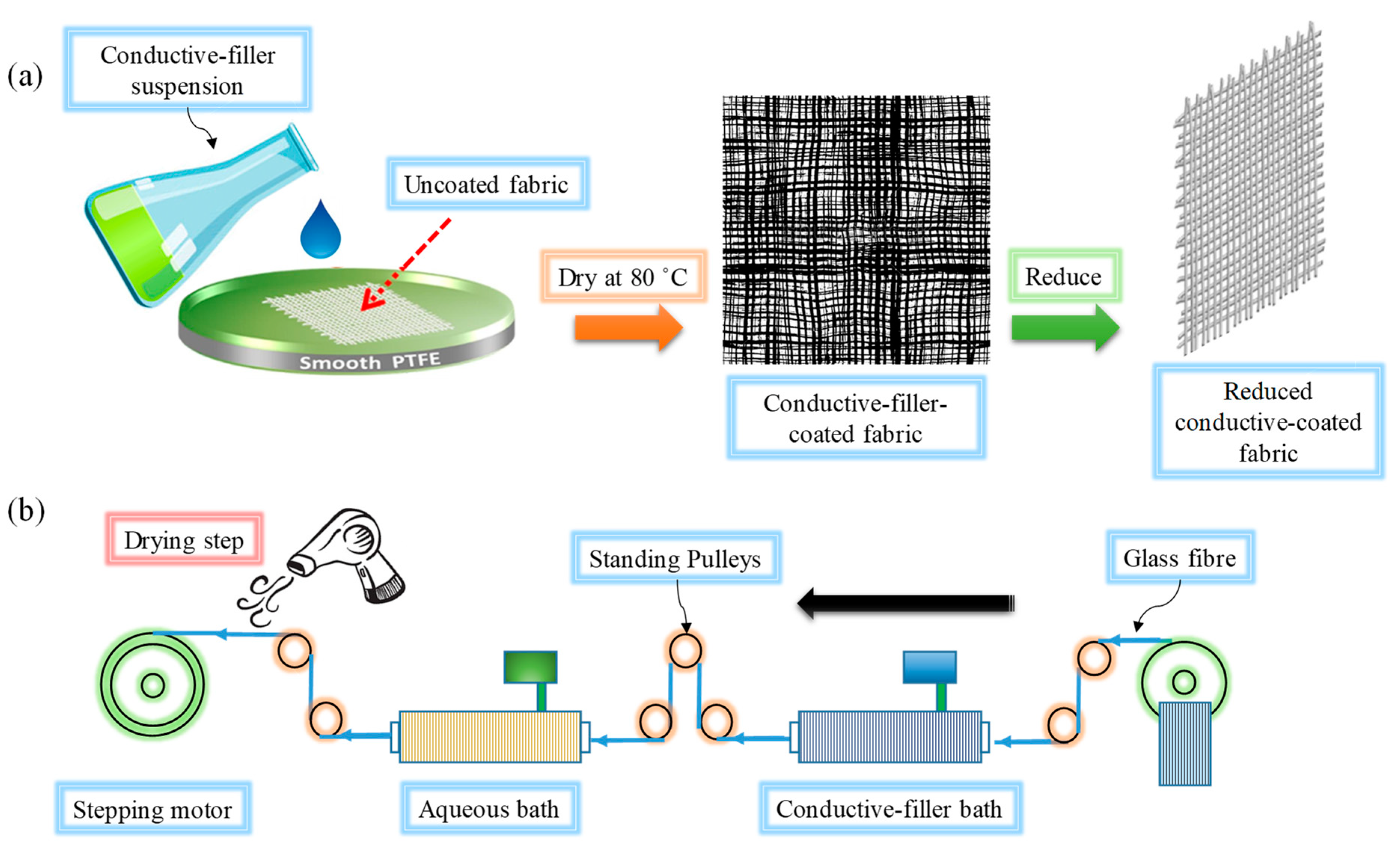
4.7.4. Dip (Solution) Coating

This is one of the most widely used methods of preparing carbon nano-materials (CNMs)/conductive fabrics and involves preparing a CNM (usually graphene) suspension in deionised water or a suitable solvent and then dipping a fabric into the solution (Figure 22). For instance, Dai et al. [205] used dip coating to fabricate composites from coated fabrics to produce in situ area sensors.
Tzounis et al. [206] employed customised blade coating, which is modified dip coating, to deposit a CNT solution onto a glass fabric to manufacture CNT/glass fabric conductive piezoresistive reinforcements. The contact between the CNMs and the fabric surface is critical because the interfacial strength ultimately influences the composite characteristics and sensor performance [207]. Tzounis et al. [208,209] improved the CNT and glass fibre interfacial strength by modifying their surfaces before dip coating. These approaches can improve the interaction between CNMs and fabrics without requiring additional treatment.
Figure 22. (a) Fabric coating process proposed by Ali et al. [210] and (b) schematic of fibre coating system.
Sustainability 15 09258 g022

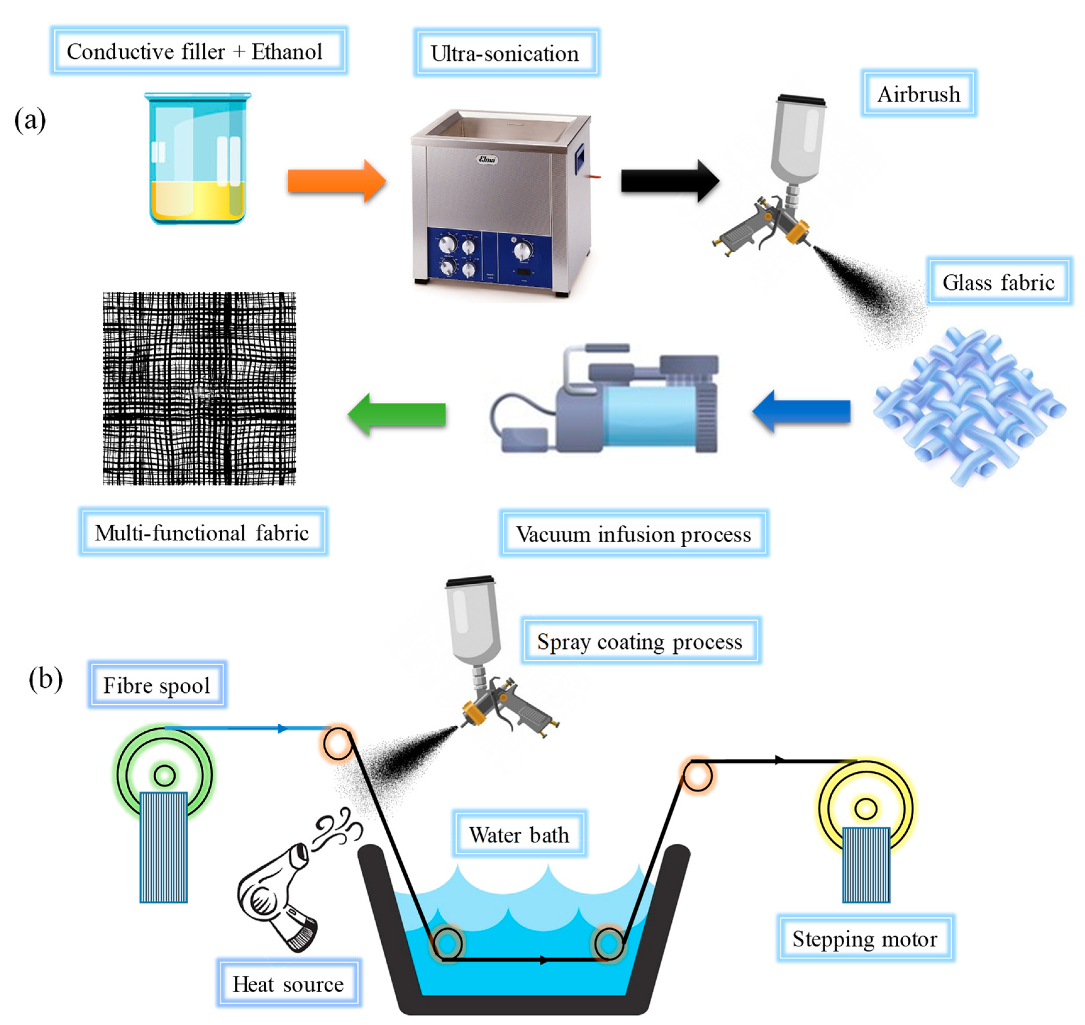
4.7.5. Spray Coating

Because of its relative convenience and scalability, spray coating is also a very convenient method of depositing CNMs directly onto reinforcements [211,212,213]. Spray coating was utilised by Rodriguez et al. [214,215,216] to coat CNTs and CNT/GO hybrids onto glass textiles and CF/epoxy pre-pregs. Spray coating was also employed by Gnidakouong et al. [217], Pinto et al. [211], and Zhang et al. [218,219] to attach CNTs to fabrics or pre-pregs. Figure 23 depicts a spray coating schematic. In this technique, because a uniform coating is prepared by manually spraying a conductive filler solution onto a fabric, achieving repeatable piezoresistivity in the final composite can be challenging. Luo et al. [220,221] continuously spray-coated a single-filament glass fibre instead of coating the entire fabric (Figure 23b). During vacuum-assisted resin transfer moulding (VARTM), the coated-fibre-based sensor (dubbed “FibSen”) was sandwiched between pre-preg layers to fabricate an in situ composite sensor. If the entire fibre tow is coated, it can also be braided into the fabric.

4.7.6. Screen Printing

In the screen printing method, a mesh is used to transfer ink (or paste), with the exception of areas made impermeable to the ink by a blocking stencil. The screen printing method is also known as serigraph printing and serigraphy. The open mesh holes on the screen are filled with ink using a blade or squeegee motion, and the screen briefly touches the substrate along a line of contact when the motion is reversed. The different electrical circuits can be printed on the surface of the host bed such as fabrics and polymer films. For a design that requires a greater and more delicate level of detail, a finer and smaller aperture for the mesh would be adopted. The mesh might be composed of a synthetic polymer, including nylon. The mesh must be installed on a frame and put under tension to function properly. Before printing, the pre-press procedure must be carried out on the frame and screen. Presses for screen printing typically come in three different configurations: flatbed, cylinder, and rotary. Rotary, flatbed, and cylinder printing are three common types of screen printing presses. Generally, different unsaturated polymeric substrates including polythiophene, polypyrrole, polyaniline, polyacetylene, polyurethane, and polystyrene containing different conductive fillers specifically CNMs are used as conductive inks or pastes [221,222,223,224,225,226,227]. A non-conductive polymer is used on the surface of the host bed as an interface layer to improve the interaction and surface condition before the printing process [221,228,229,230]. The printing of complex circuits with high delicacy, simplicity of the process, economy, and diversity of the host platform are the main advantages of this method. However, low control of layer thickness, sensitivity to humidity, and relatively low durability are among the limitations of using this method.

4.7.7. Electrophoretic Deposition

Electrophoretic deposition (EPD) involves moving and depositing charged conductive filler particles onto electrodes under electric fields (Figure 24). This approach has particularly been used to coat fabrics with CNMs such as CNTs and graphene [231,232,233,234]. Although EPD is intended to improve the uniformity of conductive filler coatings on fibre surfaces, it requires more time than dip or spray coating. Therefore, the application of EPD to large structures may be limited.

4.7.8. Chemical Vapour Deposition

Chemical vapour deposition (CVD) is a typical process for depositing a thin layer of material onto a surface. In CVD, CNMs grow directly on the host matrix surface. Unlike dip and spray coatings, which can be performed using liquids at room temperature, CVD requires relatively severe conditions to develop and deposit CNMs onto matrix surfaces [231,235,236,237]. Felisberto et al. [236] used CVD to develop CNTs on CF surfaces and improve interfacial adhesion between CFs and the epoxy matrix in laminated composites. In addition, the authors initially used dual direct current (DC) sputtering equipment to coat catalytic nickel nano-particles (NPs) onto CFs at room temperature. The re-designed CVD apparatus grew CNTs deposited on the CF surfaces. He et al. [238] also used CVD to grow CNTs on glass fibre surfaces and produce self-sensing CNT/glass fibre/epoxy composite fabrics.

5. Smart Geosynthetics Limitations

As mentioned, the concept of “smart geosynthetics” refers to the integration of sensors and monitoring technologies within geosynthetic materials used in civil engineering applications. While it offers several advantages in terms of real-time data collection and remote monitoring, there are limitations to consider, particularly in terms of durability and economic perspectives when compared with traditional monitoring techniques. Here are some limitations:
Durability is one limitation: Smart geosynthetics rely on the integration of electronic components, such as sensors and communication devices, into the geosynthetic material [239]. These electronic components may be prone to environmental factors, such as moisture, UV radiation, temperature variations, and mechanical stresses. Over time, these factors can affect the performance and durability of the electronic components, leading to potential failures or inaccurate measurements [239].
Longevity is another limitation: Geosynthetics are often used in infrastructure projects with long lifespans, such as roads, embankments, and retaining walls [5,6]. However, the electronic components integrated into smart geosynthetics may have shorter lifespans compared with the geosynthetic material itself. This can result in the need for frequent replacements or maintenance of the smart geosynthetics, which can be costly and time-consuming.
From an economic perspective, smart geosynthetics are generally more expensive than traditional geosynthetics due to the additional cost of integrating sensors and monitoring technologies [239]. The installation and maintenance of the necessary equipment for data collection and analysis also add to the overall cost. In some cases, the cost of implementing smart geosynthetics may outweigh the benefits gained from real-time monitoring, especially for projects with limited budgets or smaller-scale applications.
Another limiting factor is complexity: Implementing smart geosynthetics requires expertise in both geotechnical engineering and sensor technology. The design, installation, and calibration of the sensors and monitoring systems require specialised knowledge and skills. This complexity may increase the overall project timeline and the need for highly trained personnel, potentially leading to higher costs [239].
Compatibility is a limitation: Smart geosynthetics may not be compatible with existing infrastructure or traditional monitoring techniques. Retrofitting existing structures with smart geosynthetics can be challenging and may require significant modifications or adaptations. In some cases, it may be more practical and cost-effective to continue using traditional monitoring techniques or explore alternative solutions.
It is important to evaluate the specific project requirements and consider these limitations when deciding whether to implement smart geosynthetics or rely on traditional monitoring techniques. Each approach has its own advantages and disadvantages, and the choice should be based on a comprehensive analysis of the project’s needs, budget, and long-term goals.

6. Geosynthetic Applications

Smart geosynthetics can contribute to sustainable infrastructure development in several ways:
Early detection of issues: Smart geosynthetics integrate sensors that can monitor various parameters such as strain, deformation, temperature, and moisture content [118]. By continuously monitoring these factors, smart geosynthetics can detect early signs of potential problems, such as slope instability, soil erosion, or excessive settlement. Timely detection allows for prompt intervention and remediation, preventing more significant damage and reducing the need for costly repairs or replacements.
Improved maintenance and asset management: Real-time data provided by smart geosynthetics enable proactive maintenance and asset management [118,239]. By monitoring the condition of geosynthetic materials and their surrounding environment, infrastructure managers can make informed decisions about maintenance schedules, prioritise resources, and allocate funds more efficiently. This helps in optimising the lifespan of the infrastructure, reducing downtime, and maximising its performance.
Enhanced safety: Smart geosynthetics contribute to safer infrastructure by providing continuous monitoring and early warning systems [113]. For example, in geotechnical applications such as retaining walls or embankments, sensors embedded in smart geosynthetics can detect signs of structural instability, allowing for timely evacuation or intervention to prevent accidents or failures. This improves the overall safety for both infrastructure users and nearby communities.
Resource efficiency: By enabling real-time monitoring, smart geosynthetics can help optimise resource usage [239]. For instance, by monitoring soil moisture content, irrigation systems in green infrastructure projects can be automated to provide precise water requirements, reducing water waste and promoting efficient water management practices. Similarly, real-time data on temperature and humidity can aid in optimising energy consumption in geosynthetically lined buildings or landfills.
Data-driven decision-making: Smart geosynthetics generate a wealth of data that can be analysed and utilised for data-driven decision-making. By integrating these data with advanced analytics and machine learning algorithms, infrastructure managers can gain valuable insights into the performance of geosynthetic materials, geotechnical conditions, and environmental factors [239]. This information can guide design improvements, inform future infrastructure projects, and support evidence-based decision-making for sustainable development.
Reduced environmental impact: Smart geosynthetics can contribute to reduced environmental impact in multiple ways. By detecting and addressing issues early on, they help minimise the potential for environmental hazards and ecological damage. Additionally, by optimising maintenance and asset management, they reduce the need for extensive excavation or disruptive repairs, minimising disturbance to natural habitats. Furthermore, by facilitating resource efficiency, they support the sustainable use of water, energy, and other resources, reducing the overall environmental footprint.
By leveraging the capabilities of smart geosynthetics, sustainable infrastructure development can be achieved through improved safety, enhanced resource efficiency, proactive maintenance, and informed decision-making. However, it is crucial to consider the limitations and challenges associated with implementing and maintaining smart geosynthetics to ensure their successful integration into sustainable infrastructure projects.
Because of their numerous advantages, smart geosynthetics exhibit a wide range of applications other than geotechnical ones and are used in various fields. A summary of different smart geosynthetics used in various applications is presented in Table 6. The many advantages of using smart geosynthetics in monitoring applications include issuing warnings about imminent infrastructural damage or failure, controlling infrastructure construction, providing the data required to aid in selecting methods of remediating infrastructural damage or problem-solving techniques to manage urban development and transportation infrastructure in smart cities, and elucidating the design of unknown structures by monitoring the behaviour of existing infrastructure in the field during the infrastructure service life.

7. Future Trends and Challenges

Despite many studies conducted on materials technologies and production methods, no effective techniques for developing applicable smart geosynthetics are available yet. Although recent advances in strain gauges, fibre optics, nano-materials, conductive polymers, and self-sensing geosynthetics promise to provide appropriate solutions to developing smart geosynthetics, considerable obstacles remain to applying smart geosynthetics to continuously, feasibly, and reliably monitor and reinforce infrastructure in real time, some of which are outlined as follows:
  • Because soil contains corrosive organic, inorganic, and chemical substances and because of naturally destructive climate cycles, smart geosynthetics should be designed and manufactured such that these factors do not interfere with monitoring systems and structural reinforcements.
  • Smart geosynthetics should be designed and produced such that they exhibit appropriate inter-twining between the host matrix and the sensing elements so that the strain and stress applied to the geosynthetic components are properly reflected by the sensing system.
  • Owing to the widespread application of geosynthetics in many large projects, geosynthetics should be produced as cost-effectively and simply as possible so that they are easily industrially scalable.
  • Smart geosynthetics should be simply designed to minimise the need for support and complementary systems including wires, electrodes, capacitors, power supplies, data acquisition, analysers, receivers, and transmitters to prevent damage during storage, transport, implementation, and the device service life. These components also cause sectional discontinuities and increase installation and maintenance costs.
  • To electrically insulate smart geosynthetic products against the surrounding environment while minimising the installation damage, a durable, non-conductive, UV-protective shield should be developed to protect smart geosynthetics.
  • When nano-particles, particularly CNMs, are used to develop smart geosynthetic materials, the nano-particles should be well dispersed throughout the polymer matrix through a feasible and compatible method to prevent the nano-particles from possibly adversely affecting the mechanical and microstructural properties and the durability of the host matrix.
  • Owing to the widespread application of geosynthetics to infrastructure, especially in nature, environmental issues must be considered in all geosynthetic production aspects.
  • To mitigate adverse weather conditions such as moisture and water infiltration, temperature variations, UV radiation, and wind and mechanical stresses on smart geosynthetics, appropriate measures including proper design and material selection, protective measures, regular inspection and maintenance, and calibration and testing processes should be considered.
  • While smart geosynthetics offer various benefits, they can also present certain environmental issues such as e-waste generation, material recycling and disposal, energy consumption, and greenhouse gas emissions during manufacturing processes. To address these environmental issues, the following measures can be considered:
Promote extended producer responsibility (EPR) programs to ensure responsible management of electronic waste generated from smart geosynthetics.
Encourage research and development to improve the recyclability and biodegradability of geosynthetic materials.
Implement life cycle assessment (LCA) and eco-design principles to minimise the environmental impact of smart geosynthetics from the design stage.
Increase awareness and education among stakeholders regarding the proper disposal and recycling options for smart geosynthetics.
Support sustainable manufacturing practices, including the use of renewable energy sources and eco-friendly materials.
Implement environmentally responsible installation practices, such as minimising ground disturbance and employing erosion control measures.

8. Concluding Remarks

Geosynthetics are manufactured synthetic substances (such as hydrocarbon chains or polymers) employed in a wide range of engineering applications. Various factors such as inherent variability, material aging, over-loading, prolonged use and duty cycles, environmental corrosion, and lack of adequate inspection and maintenance weaken the soil mass, enable micro-cracks to extend over time, and lead to sudden catastrophic collapse. However, timely monitoring and proper maintenance of the soil mass can markedly improve the infrastructure service life and prevent sudden failures. Multi-functional geosynthetics can be used for applications such as extracting and transmitting information about the stress, strain, deformation, damage, and temperature of the systems into which they are incorporated in addition to performing their traditional roles. This paper reviews a wide range of technologies, manufacturing processes, materials, and methods that have been used to develop smart geosynthetics to date. The various applications of multi-functional geosynthetics and the future challenges have also been discussed to pave the way for developing applicable smart geosynthetics.
This review demonstrates that self-sensing geosynthetic technology could lead to the development of a more economical and reliable alternative to conventional smart geosynthetics (e.g., sensor-embedded and OF-encapsulated geosynthetics). A summary of the limitations and advantages of different smart geosynthetic technologies developed for infrastructural monitoring is presented in Table 7. Self-sensing geosynthetics technology is more cost-effective owing to the lack of complex and expensive analyser and data acquisition system requirements, which are usually used for other conventional smart geosynthetics and instrumentations. Self-sensing geosynthetics may also improve the precision of measured parameters such as strain, stress, and deformation. In-isolation tensile tests are commonly used to calibrate strain gauges or OF-encapsulated geosynthetics. However, interlocking impacts and soil confining pressure could cause considerable inaccuracies in these parameters and, subsequently, in strains measured using geosynthetics in the field. Furthermore, strain gauges and OF sensors encapsulated in the geosynthetic layer usually form local “hard spots” that cause global tensile strains to be under-registered, thereby potentially rendering the detection of impending infrastructure failures fruitless.
Self-sensing geosynthetics avoid these limitations by integrating self-sensing functionality into the host polymer matrix and products and could be a convenient solution to developing long-term, reliable, real-time, and feasible infrastructure monitoring systems. However, self-sensing geosynthetics development technology remains in its infancy and must overcome these challenges.

Author Contributions

M.A., R.F., A.G.C. and J.S.: conceptualization, methodology, data curation, writing—original draft preparation, project administration, supervision, writing—review and editing. All authors have read and agreed to the published version of the manuscript.

Funding

The authors acknowledge the support provided by a Fundacao para a Ciencia e a Tecnologia (FCT) individual fellowship with the reference number “2021.07596.BD”.

Institutional Review Board Statement

Not applicable.

Informed Consent Statement

This study does not contain any studies involving human or animal participants.

Data Availability Statement

Requests for all types of data used to support the findings of this study, after the publication of this article, will be considered by the corresponding author, subject to obtaining permission from the owners.

Conflicts of Interest

The authors declare no conflict of interest.

Abbreviations

ABSAcrylonitrile butadiene styrene
ASTMAmerican Society for Testing and Materials
BCRBraided composite rods
BOTDABrillouin optical time domain
BOTDRBrillouin optical time domain analysis
CBCarbon black
CFCarbon fibre
CFTCarbon fibre tow
CNFCarbon nano-fibre
CNMCarbon nano-material
CNT Carbon nano-tube
Cu–NiCopper–nickel
CVDChemical vapour deposition
DOFSDistributed optical fibre sensor
EPDElectrophoretic deposition
FBGFibre Bragg grating
FDMFused-deposition modelling
FRPFibre-reinforced polymer
HDPEHigh-density polyethylene
HOMOHighest occupied molecular orbital
LDPELow-density polyethylene
LUMOLowest unoccupied molecular orbital
MWCNT Multi-wall carbon nano-tube
NPNickel nano-particle
OFOptical fibre
OSAOptical spectrum analyser
PAPhytic acid
PAAMPSAPoly 2-acrylamido-2-methyl-1-propanesulfonic acid
PANIPolyaniline
PDMSPoly dimethyl siloxane
PEDOT Poly 3,4-ethylenedioxythiophene
PLAPolylactic acid
PPPolypropylene
PVCPolyvinyl chloride
PVPPolyvinylpyrrolidone
SHMStructural health monitoring
SWCNTSingle-wall carbon nano-tube
TPThermoplastic matrix
TPUThermoplastic polyurethane
VARTMVacuum-assisted resin transfer moulding

References

  1. Touze-Foltz, N.; Bannour, H.; Barral, C.; Stoltz, G. A review of the performance of geosynthetics for environmental protection. Geotext. Geomembr. 2016, 44, 656–672. [Google Scholar] [CrossRef]
  2. Arjomand, M.; Abedi, M.; Gharib, M.; Damghani, M. An Experimental Study on Geogrid with Geotextile Effects Aimed to Improve Clayey Soil. Int. J. Eng. 2019, 32, 685–692. [Google Scholar]
  3. Hatami, K.; Fathi, A.; Grady, B. Development of Sensor-Enabled Geosynthetics (SEG) for Health Monitoring of Reinforced Soil Structures. Geo-Frontiers 2011, 2183–2193. [Google Scholar]
  4. Wu, H.; Yao, C.; Li, C.; Miao, M.; Zhong, Y.; Lu, Y.; Liu, T.J.M. Review of application and innovation of geotextiles in geotechnical engineering. Materials 2020, 13, 1774. [Google Scholar] [CrossRef] [PubMed] [Green Version]
  5. Li, J.; Cui, X.-Z.; Jin, Q.; Su, J.-W.; Cui, S.-Q.; Wang, Y.-L. Laboratory investigation of the durability of a new smart geosynthetic material. Constr. Build. Mater. 2018, 169, 28–33. [Google Scholar] [CrossRef]
  6. Wang, Z.; Richwien, W. A study of soil-reinforcement interface friction. J. Geotech. Geoenviron. Eng. 2002, 128, 92–94. [Google Scholar] [CrossRef]
  7. Zhang, J.; She, R.; Xia, S.; Dai, Z.; Hu, N.; Cui, X.; Han, R.; Ming, R.; Ma, G. Development and laboratory evaluation of a self-monitoring polymer geobelts. Measurement 2020, 166, 108214. [Google Scholar] [CrossRef]
  8. Hatami, K.; Grady, B.P.; Ulmer, M.C. Sensor-Enabled Geosynthetics: Use of Conducting Carbon Networks as Geosynthetic Sensors. J. Geotech. Geoenviron. Eng. 2009, 135, 863–874. [Google Scholar] [CrossRef]
  9. Gesualdo, A.; Fortunato, A.; Penta, F.; Monaco, M. Structural identification of tall buildings: A reinforced concrete structure as a case study. Case Stud. Constr. Mater. 2021, 15, e00701. [Google Scholar] [CrossRef]
  10. Sun, Y.; Xu, H.; Gu, P.; Hu, W. Application of FBG sensing technology in stability analysis of geogrid-reinforced slope. Sensors 2017, 17, 597. [Google Scholar] [CrossRef] [Green Version]
  11. Iannuzzo, A.; Serio, F.D.; Gesualdo, A.; Zuccaro, G.; Fortunato, A.; Angelillo, M. Crack patterns identification in masonry structures with a C° displacement energy method. Int. J. Mason. Res. Innov. 2018, 3, 295–323. [Google Scholar] [CrossRef]
  12. Jones, C.; Lamont-Black, J.; Glendinning, S.; Pugh, R. New applications for smart geosynthetics. Waste Contain. Remediat. 2005, 1–15. [Google Scholar]
  13. Petit, C.; Lesueur, D.; Millien, A.; Leguernevel, G.; Dopeux, J.; Picoux, B.; Allou, F.; Terhani, F. Smart geosynthetics for strain measurements in asphalt pavements. In Proceedings of the 13th International Conference on Asphalt Pavements, Fortaleza, Brazil, 19–22 June 2018; pp. 19–21. [Google Scholar]
  14. Shariati, M.; Azar, S.M.; Arjomand, M.-A.; Tehrani, H.S.; Daei, M.; Safa, M. Evaluating the impacts of using piles and geosynthetics in reducing the settlement of fine-grained soils under static load. Geomech. Eng. 2020, 20, 87–101. [Google Scholar]
  15. Pamukcu, S.; Turel, M. Use of BOTDR to Measure Distributed Strains of Geosynthetics; GRI-20: Washington, DC, USA, 2007. [Google Scholar]
  16. Paylor, M.; Christopher, B.; Nyren, R. Intelligent geosynthetics used for performance monitoring and construction control, Woodrow Wilson Bridge—Maryland portion. In Proceedings of the GeoAmericas 2008, 1st Pan American Geosynthetics Conf. and Exhibition, Cancun, Mexico, 1–5 March 2008; pp. 744–753. [Google Scholar]
  17. Bi, G.; Yang, S.; Wu, Y.; Sun, Y.; Xu, H.; Zhu, B.; Huang, C.; Cao, S. A preliminary study of the application of the strain-self-sensing smart geogrid rib in expansive soils. Geotext. Geomembr. 2023, 51, 275–281. [Google Scholar] [CrossRef]
  18. Liu, X.; Xiao, J.; Cai, D.; Su, Q.; Yang, G.; Yuan, S.; Jiang, G. Recent advances in subgrade engineering for high-speed railway. Intell. Transp. Infrastruct. 2023, 2, liad001. [Google Scholar] [CrossRef]
  19. Sun, Z.; Li, H.; Bao, Y.; Meng, X.; Zhang, D. Intelligent Risk Prognosis and Control of Foundation Pit Excavation Based on Digital Twin. Buildings 2023, 13, 247. [Google Scholar] [CrossRef]
  20. Rowe, R.K.; Gnanendran, C.T. Geotextile strain in a full scale reinforced test embankment. Geotext. Geomembr. 1994, 13, 781–806. [Google Scholar] [CrossRef]
  21. Springman, S.; Bolton, M.; Sharma, J.; Balachandran, S. Modelling and instrumentation of a geotextile in the geotechnical centrifuge. In Proceedings of the International Symposium on Earth Reinforcment Practice, Kyushu, Japan, 12–14 November 1996; Balkema: Rotterdam, The Netherlands, 1992; p. 172. [Google Scholar]
  22. Bolton, M.; Sharma, J. Embankments with base reinforcement on soft clay. In Proceedings of the International Conference on Centrifugal, Singapore, 31 August–2 September 1994; pp. 587–592. [Google Scholar]
  23. Gnanendran, C.T.; Selvadurai, A.P.S. Strain measurement and interpretation of stabilising force in geogrid reinforcement. Geotext. Geomembr. 2001, 19, 177–194. [Google Scholar] [CrossRef]
  24. Viswanadham, B.V.S.; König, D. Studies on scaling and instrumentation of a geogrid. Geotext. Geomembr. 2004, 22, 307–328. [Google Scholar] [CrossRef]
  25. Wong, W.C.; Chan, C.C.; Chen, L.H.; Li, T.; Lee, K.X.; Leong, K.C. Polyvinyl alcohol coated photonic crystal optical fiber sensor for humidity measurement. Sens. Actuators B Chem. 2012, 174, 563–569. [Google Scholar] [CrossRef]
  26. Güemes, A.; Messervey, T. Smart textile and polymer fibres for structural health monitoring. In Textiles, Polymers and Composites for Buildings; Elsevier: Amsterdam, The Netherlands, 2010; pp. 330–350. [Google Scholar]
  27. Bögner-Balz, H.; Blum, R.; Köhnlein, J. 4-Structural behaviour of fabrics and coatings for architectural fabric structures. In Fabric Structures in Architecture; de Llorens, J.I., Ed.; Woodhead Publishing: Sawston, UK, 2015; pp. 123–157. [Google Scholar] [CrossRef]
  28. Alwis, L.; Sun, T.; Grattan, K.T.V. Optical fibre-based sensor technology for humidity and moisture measurement: Review of recent progress. Measurement 2013, 46, 4052–4074. [Google Scholar] [CrossRef]
  29. Vorathin, E.; Hafizi, Z.M.; Ismail, N.; Loman, M. Review of high sensitivity fibre-optic pressure sensors for low pressure sensing. Opt. Laser Technol. 2020, 121, 105841. [Google Scholar] [CrossRef]
  30. Wang, J.; Bian, C.; Gang, T.; Hu, M. High-sensitive Mach-Zehnder interferometer for humidity measurements based on concatenating single-mode concave cone and core-offset. Optik 2020, 208, 164465. [Google Scholar] [CrossRef]
  31. Zhou, X.; Yu, Q.; Peng, W. Fiber-optic Fabry–Perot pressure sensor for down-hole application. Opt. Lasers Eng. 2019, 121, 289–299. [Google Scholar] [CrossRef]
  32. Xia, L.; Li, L.; Li, W.; Kou, T.; Liu, D. Novel optical fiber humidity sensor based on a no-core fiber structure. Sens. Actuators A Phys. 2013, 190, 1–5. [Google Scholar] [CrossRef]
  33. Zhao, Z.; Duan, Y. A low cost fiber-optic humidity sensor based on silica sol–gel film. Sens. Actuators B Chem. 2011, 160, 1340–1345. [Google Scholar] [CrossRef]
  34. Johannisson, P.; Agrell, E. Modeling of Nonlinear Signal Distortion in Fiber-Optic Networks. J. Light. Technol. 2014, 32, 4544–4552. [Google Scholar] [CrossRef] [Green Version]
  35. Ming Gang, X.; Geiger, H.; Dakin, J.P. Modeling and performance analysis of a fiber Bragg grating interrogation system using an acousto-optic tunable filter. J. Light. Technol. 1996, 14, 391–396. [Google Scholar] [CrossRef]
  36. Golani, O.; Dar, R.; Feder, M.; Mecozzi, A.; Shtaif, M. Modeling the Bit-Error-Rate Performance of Nonlinear Fiber-Optic Systems. J. Light. Technol. 2016, 34, 3482–3489. [Google Scholar] [CrossRef]
  37. Yurchenko, A.V.; Mekhtiyev, A.D.; Bulatbayev, F.N.; Neshina, Y.G.; Alkina, A.D. The Model of a Fiber-Optic Sensor for Monitoring Mechanical Stresses in Mine Workings. Russ. J. Nondestruct. Test. 2018, 54, 528–533. [Google Scholar] [CrossRef]
  38. Zhang, Z.; Fang, Z.; Stefani, J.; DiSiena, J.; Bevc, D.; Ning, I.L.C.; Hughes, K.; Tan, Y. Modeling of fiber-optic strain responses to hydraulic fracturing. Geophysics 2020, 85, A45–A50. [Google Scholar] [CrossRef]
  39. Cacciuttolo, C.; Pastor, A.; Valderrama, P.; Atencio, E. Process Water Management and Seepage Control in Tailings Storage Facilities: Engineered Environmental Solutions Applied in Chile and Peru. Water 2023, 15, 196. [Google Scholar] [CrossRef]
  40. Liu, X.-F.; Zhu, H.-H.; Wu, B.; Li, J.; Liu, T.-X.; Shi, B. Artificial intelligence-based fiber optic sensing for soil moisture measurement with different cover conditions. Measurement 2023, 206, 112312. [Google Scholar] [CrossRef]
  41. Howiacki, T.; Sieńko, R.; Bednarski, Ł.; Zuziak, K. Crack Shape Coefficient: Comparison between Different DFOS Tools Embedded for Crack Monitoring in Concrete. Sensors 2023, 23, 566. [Google Scholar] [CrossRef]
  42. Xie, X.; Fang, X.; Liu, H.; Xing, X.; Liang, M.; Wu, G.; Chen, N. Development and application of a borehole stress meter in rocks surrounding the roadway, based on optical-fiber sensing technology. Front. Earth Sci. 2023, 10, 1122579. [Google Scholar] [CrossRef]
  43. Wang, D.-Y.; Zhu, H.-H.; Wang, J.; Sun, Y.-J.; Schenato, L.; Pasuto, A.; Bin, S. Characterization of sliding surface deformation and stability evaluation of landslides with fiber–optic strain sensing nerves. Eng. Geol. 2023, 314, 107011. [Google Scholar] [CrossRef]
  44. Kouroussis, G.; Caucheteur, C.; Kinet, D.; Alexandrou, G.; Verlinden, O.; Moeyaert, V. Review of trackside monitoring solutions: From strain gages to optical fibre sensors. Sensors 2015, 15, 20115–20139. [Google Scholar] [CrossRef] [Green Version]
  45. Hernaez, M.; Zamarreño, C.R.; Melendi-Espina, S.; Bird, L.R.; Mayes, A.G.; Arregui, F.J. Optical fibre sensors using graphene-based materials: A review. Sensors 2017, 17, 155. [Google Scholar] [CrossRef] [Green Version]
  46. Correia, R.; James, S.; Lee, S.; Morgan, S.; Korposh, S. Biomedical application of optical fibre sensors. J. Opt. 2018, 20, 073003. [Google Scholar] [CrossRef]
  47. Chen, W.; Wang, J.; Wan, F.; Wang, P. Review of optical fibre sensors for electrical equipment characteristic state parameters detection. High Volt. 2019, 4, 271–281. [Google Scholar] [CrossRef]
  48. Campanella, C.E.; Cuccovillo, A.; Campanella, C.; Yurt, A.; Passaro, V. Fibre Bragg grating based strain sensors: Review of technology and applications. Sensors 2018, 18, 3115. [Google Scholar] [CrossRef] [PubMed] [Green Version]
  49. Zangani, D. Smart high-performance textiles for protection in construction and geotechnical applications. In Smart Textiles for Protection; Elsevier: Amsterdam, The Netherlands, 2013; pp. 276–305. [Google Scholar]
  50. Hong, C.-Y.; Zhang, Y.-F.; Li, G.-W.; Zhang, M.-X.; Liu, Z.-X. Recent progress of using Brillouin distributed fiber optic sensors for geotechnical health monitoring. Sens. Actuators A Phys. 2017, 258, 131–145. [Google Scholar] [CrossRef]
  51. Benzhang, W.; Chao, P.; Dengwang, Z.; Yongkang, D. Advances of key technologies in long-range distributed Brillouin optical fiber sensing. Opto-Electron. Eng. 2018, 45, 170484–170410–170484–170481. [Google Scholar]
  52. Wu, T.; Liu, G.; Fu, S.; Xing, F. Recent progress of fiber-optic sensors for the structural health monitoring of civil infrastructure. Sensors 2020, 20, 4517. [Google Scholar] [CrossRef] [PubMed]
  53. Klar, A.; Linker, R. Feasibility study of automated detection of tunnel excavation by Brillouin optical time domain reflectometry. Tunn. Undergr. Space Technol. 2010, 25, 575–586. [Google Scholar] [CrossRef]
  54. Enckell, M.; Glisic, B.; Myrvoll, F.; Bergstrand, B. Evaluation of a large-scale bridge strain, temperature and crack monitoring with distributed fibre optic sensors. J. Civ. Struct. Health Monit. 2011, 1, 37–46. [Google Scholar] [CrossRef]
  55. Minardo, A.; Persichetti, G.; Testa, G.; Zeni, L.; Bernini, R. Long term structural health monitoring by Brillouin fibre-optic sensing: A real case. J. Geophys. Eng. 2012, 9, S64–S69. [Google Scholar] [CrossRef]
  56. Chapeleau, X.; Sedran, T.; Cottineau, L.-M.; Cailliau, J.; Taillade, F.; Gueguen, I.; Henault, J.-M. Study of ballastless track structure monitoring by distributed optical fiber sensors on a real-scale mockup in laboratory. Eng. Struct. 2013, 56, 1751–1757. [Google Scholar] [CrossRef]
  57. Barrias, A.; Casas, J.R.; Villalba, S. A review of distributed optical fiber sensors for civil engineering applications. Sensors 2016, 16, 748. [Google Scholar] [CrossRef] [Green Version]
  58. Glisic, B. Distributed fiber optic sensing technologies and applications—An overview. Spec. Publ. 2013, 292, 1–18. [Google Scholar]
  59. Cheung, L.L.K.; Soga, K.; Bennett, P.J.; Kobayashi, Y.; Amatya, B.; Wright, P. Optical fibre strain measurement for tunnel lining monitoring. Proc. Inst. Civ. Eng. Geotech. Eng. 2010, 163, 119–130. [Google Scholar] [CrossRef]
  60. Mohamad, H.; Bennett, P.; Soga, K.; Mair, R.; Bowers, K. Behaviour of an old masonry tunnel due to tunnelling-induced ground settlement. Géotechnique 2010, 60, 927–938. [Google Scholar] [CrossRef]
  61. Gue, C.Y.; Wilcock, M.; Alhaddad, M.; Elshafie, M.; Soga, K.; Mair, R.J. The monitoring of an existing cast iron tunnel with distributed fibre optic sensing (DFOS). J. Civ. Struct. Health Monit. 2015, 5, 573–586. [Google Scholar] [CrossRef] [Green Version]
  62. Hong, C.; Yin, J.; Pei, H.; Xu, D. Application of fiber optic sensors in pullout testing of model soil nails. In Proceedings of the 14th Asian Regional Conference on Soil Mechanics and Geotechnical Engineering, ARC, Hong Kong, China, 23–27 May 2011. [Google Scholar]
  63. Wright, P. Assessment of London underground tube tunnels-investigation, monitoring and analysis. Smart Struct. Syst. 2010, 6, 239–262. [Google Scholar] [CrossRef]
  64. Guangqing, W.; Bin, S.; Xiaokui, Y.; Chunde, P.; Youqun, Z.; Baojun, W. BOTDR based distributed strain test on bored pile buried in complicated geological ground. J. Eng. Geol. 2008, 16, 826–832. [Google Scholar]
  65. Piao, C.D.; Shi, B.; Gao, L. Characteristics and application of BOTDR in distributed detection of pile foundation. Adv. Mater. Res. 2010, 163–167, 2657–2665. [Google Scholar] [CrossRef]
  66. Liu, W.; Wang, H.; Zhou, Z.; Xing, X.; Cao, D.; Jiang, Z. Optical fiber-based sensors with flexible encapsulation for pavement behavior monitoring. Struct. Control. Health Monit. 2015, 22, 301–313. [Google Scholar] [CrossRef]
  67. Wang, B.-j.; Li, K.; Shi, B.; Wei, G.-q. Test on application of distributed fiber optic sensing technique into soil slope monitoring. Landslides 2009, 6, 61–68. [Google Scholar] [CrossRef]
  68. Nöther, N.; Glötzl, R.; Vollmert, L.; Ehrenberg, H.; Weisemann, U.; Großmann, S.; Oehmichen, R. Displacement Monitoring in geotechnical applications using optical fiber sensors in geosynthetics. In Proceedings of the 6th European Workshop on Structural Health Monitoring, Dresden, Germany, 3–6 July 2012; pp. 2–6. [Google Scholar]
  69. Habel, W.R.; Krebber, K. Fiber-optic sensor applications in civil and geotechnical engineering. Photonic Sens. 2011, 1, 268–280. [Google Scholar] [CrossRef] [Green Version]
  70. Nöther, N. Distributed Fiber Sensors in River Embankments: Advancing and Implementing the Brillouin Optical Frequency Domain Analysis; Bundesanstalt für Materialforschung und-prüfung (BAM): Berlin, Germany, 2010.
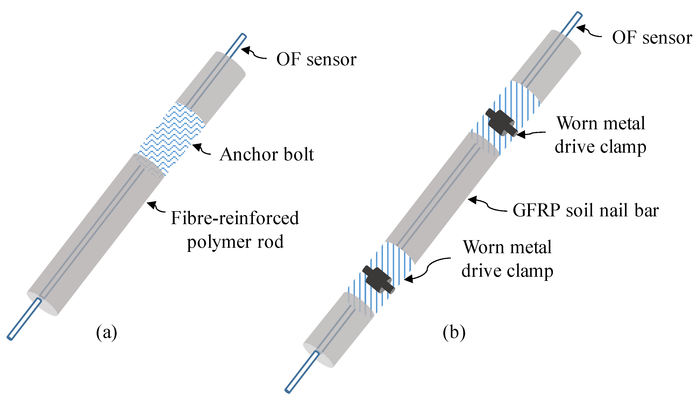
  71. Hong, C.-Y.; Yin, J.-H.; Zhang, Y.-F. Deformation monitoring of long GFRP bar soil nails using distributed optical fiber sensing technology. Smart Mater. Struct. 2016, 25, 085044. [Google Scholar] [CrossRef]
  72. Shayanfar, J.; Barros, J.A.O.; Rezazadeh, M. Analytical model to predict axial stress-strain behavior of heat-damaged unreinforced concrete columns wrapped by FRP jacket. Eng. Struct. 2023, 289, 116244. [Google Scholar] [CrossRef]
  73. Shayanfar, J.; Barros, J.A.; Rezazadeh, M. Cross-sectional and confining system unification on peak compressive strength of FRP confined concrete. Struct. Concr. 2023, 24, 1531–1545. [Google Scholar] [CrossRef]
  74. Shayanfar, J.; Barros, J.A.; Rezazadeh, M. Analysis-oriented model for partially FRP-and-steel-confined circular RC columns under compression. Eng. Struct. 2023, 276, 115330. [Google Scholar] [CrossRef]
  75. Huang, M.; Zhou, Z.; Huang, Y.; Ou, J. A distributed self-sensing FRP anchor rod with built-in optical fiber sensor. Measurement 2013, 46, 1363–1370. [Google Scholar] [CrossRef]
  76. Misra, A.; Chen, C.-H.; Oberoi, R.; Kleiber, A. Simplified analysis method for micropile pullout behavior. J. Geotech. Geoenviron. Eng. 2004, 130, 1024–1033. [Google Scholar] [CrossRef]
  77. Hong, C.-Y.; Yin, J.-H.; Zhou, W.-H.; Pei, H.-F. Analytical study on progressive pullout behavior of a soil nail. J. Geotech. Geoenviron. Eng. 2012, 138, 500–507. [Google Scholar] [CrossRef]
  78. Shi, B.; Sui, H.; Liu, J.; Zhang, D. The BOTDR-based distributed monitoring system for slope engineering. In Proceedings of the 10th IAEG International Congress, Nottingham, UK, 6–10 September 2006; pp. 6–10. [Google Scholar]
  79. Mohamad, H.; Soga, K.; Amatya, B. Thermal strain sensing of concrete piles using Brillouin optical time domain reflectometry. Geotech. Test. J. 2014, 37, 333–346. [Google Scholar] [CrossRef]
  80. Mohamad, H.; Soga, K.; Pellew, A.; Bennett, P.J. Performance monitoring of a secant-piled wall using distributed fiber optic strain sensing. J. Geotech. Geoenviron. Eng. 2011, 137, 1236–1243. [Google Scholar] [CrossRef]
  81. Nöther, N.; Wosniok, A.; Krebber, K.; Thiele, E. A distributed fiber optic sensor system for dike monitoring using Brillouin optical frequency domain analysis. In Proceedings of the Smart Sensor Phenomena, Technology, Networks, and Systems, San Diego, CA, USA, 10–12 March 2008; p. 69330T. [Google Scholar]
  82. Iten, M.; Puzrin, A.M. BOTDA road-embedded strain sensing system for landslide boundary localization. In Proceedings of the Smart Sensor Phenomena, Technology, Networks, and Systems, San Diego, CA, USA, 9–11 March 2009; p. 729316. [Google Scholar]
  83. Nikles, M. Long-distance fiber optic sensing solutions for pipeline leakage, intrusion, and ground movement detection. In Proceedings of the Fiber Optic Sensors and Applications VI, Orlando, FL, USA, 15–17 April 2009; p. 731602. [Google Scholar]
  84. Lanticq, V.; Bourgeois, E.; Magnien, P.; Dieleman, L.; Vinceslas, G.; Sang, A.; Delepine-Lesoille, S. Soil-embedded optical fiber sensing cable interrogated by Brillouin optical time-domain reflectometry (B-OTDR) and optical frequency-domain reflectometry (OFDR) for embedded cavity detection and sinkhole warning system. Meas. Sci. Technol. 2009, 20, 034018. [Google Scholar] [CrossRef]
  85. Inaudi, D.; Glisic, B. Long-range pipeline monitoring by distributed fiber optic sensing. In Proceedings of the International Pipeline Conference, Calgary, AB, Canada, 25–29 September 2006; pp. 763–772. [Google Scholar]
  86. Gao, L.; Ji, B.; Kong, G.; Huang, X.; Li, M.; Mahfouz, A.H. Distributed measurement of temperature for PCC energy pile using BOFDA. J. Sens. 2015, 2015, 610473. [Google Scholar] [CrossRef] [Green Version]
  87. Minardo, A.; Damiano, E.; Olivares, L.; Picarelli, L.; Zeni, L.; Avolio, B.; Coscetta, A. Soil slope monitoring by use of a Brillouin distributed sensor. In Proceedings of the Fotonica AEIT Italian Conference on Photonics Technologies, Turin, Italy, 6–8 May 2015; p. 156. [Google Scholar]
  88. Madjdabadi, B.; Valley, B.; Dusseault, M.B.; Kaiser, P.K. Experimental evaluation of a distributed Brillouin sensing system for measuring extensional and shear deformation in rock. Measurement 2016, 77, 54–66. [Google Scholar] [CrossRef]
  89. Aziz, S.; Chang, S.-H. Smart-fabric sensor composed of single-walled carbon nanotubes containing binary polymer composites for health monitoring. Compos. Sci. Technol. 2018, 163, 1–9. [Google Scholar] [CrossRef]
  90. Hegedus, G.; Sarkadi, T.; Czigany, T. Self-sensing polymer composite: White-light-illuminated reinforcing fibreglass bundle for deformation monitoring. Sensors 2019, 19, 1745. [Google Scholar] [CrossRef] [Green Version]
  91. Alsaadi, A.; Meredith, J.; Swait, T.; Curiel-Sosa, J.; Jia, Y.; Hayes, S. Structural health monitoring for woven fabric CFRP laminates. Compos. Part B Eng. 2019, 174, 107048. [Google Scholar] [CrossRef]
  92. Abedi, M.; Fangueiro, R.; Gomes Correia, A. A review of intrinsic self-sensing cementitious composites and prospects for their application in transport infrastructures. Constr. Build. Mater. 2021, 310, 125139. [Google Scholar] [CrossRef]
  93. Abedi, M.; Fangueiro, R.; Camões, A.; Gomes Correia, A. Evaluation of CNT/GNP’s synergic effects on the Mechanical, Microstructural, and durability properties of a cementitious composite by the novel dispersion method. Constr. Build. Mater. 2020, 260, 120486. [Google Scholar] [CrossRef]
  94. Rana, S.; Subramani, P.; Fangueiro, R.; Correia, A.G. A review on smart self-sensing composite materials for civil engineering applications. AIMS Mater. Sci. 2016, 3, 357–379. [Google Scholar] [CrossRef]
  95. Han, B.; Yu, X.; Ou, J. Self-Sensing Concrete in Smart Structures; Butterworth-Heinemann: Oxford, UK, 2014. [Google Scholar]
  96. Abedi, M.; Fangueiro, R.; Correia, A.G. Effects of electrodes layout and filler scale on percolation threshold and piezoresistivity performances of a cementitious-based geocomposite. Nanomaterials 2022, 12, 1734. [Google Scholar] [CrossRef]
  97. Abedi, M.; Correia, A.G.; Fangueiro, R. Geotechnical and piezoresistivity properties of sustainable cementitious stabilized sand reinforced with recycled fibres. Transp. Eng. 2021, 6, 100096. [Google Scholar] [CrossRef]
  98. Abedi, M.; Hassanshahi, O.; Rashiddel, A.; Ashtari, H.; Seddik Meddah, M.; Dias, D.; Arjomand, M.A.; Keong Choong, K. A sustainable cementitious composite reinforced with natural fibers: An experimental and numerical study. Constr. Build. Mater. 2023, 378, 131093. [Google Scholar] [CrossRef]
  99. Abedi, M.; Fangueiro, R.; Correia, A.G. Development of a Novel Multifunctional Cementitious-Based Geocomposite by the Contribution of CNT and GNP. Nanomaterials 2021, 11, 961. [Google Scholar] [CrossRef] [PubMed]
  100. Abedi, M.; Fangueiro, R.; Gomes Correia, A. Ultra-sensitive affordable cementitious composite with high mechanical and microstructural performances by hybrid CNT/GNP. Materials 2020, 13, 3484. [Google Scholar] [CrossRef] [PubMed]
  101. Abedi, M.; Fangueiro, R.; Correia, A.G. An Effective Method for Hybrid CNT/GNP Dispersion and Its Effects on the Mechanical, Microstructural, Thermal, and Electrical Properties of Multifunctional Cementitious Composites. J. Nanomater. 2020, 2020, 6749150. [Google Scholar] [CrossRef]
  102. Abedi, M.; Fangueiro, R.; Gomes Correia, A. Innovative self-sensing fiber-reinforced cemented sand with hybrid CNT/GNP. Smart Mater. Struct. 2021, 30, 105034. [Google Scholar] [CrossRef]
  103. Salvado, R.; Lopes, C.; Szojda, L.; Araújo, P.; Gorski, M.; Velez, F.J.; Castro-Gomes, J.; Krzywon, R. Carbon fiber epoxy composites for both strengthening and health monitoring of structures. Sensors 2015, 15, 10753–10770. [Google Scholar] [CrossRef] [Green Version]
  104. Jerkovic, I.; Koncar, V.; Grancaric, A.M. New textile sensors for in situ structural health monitoring of textile reinforced thermoplastic composites based on the conductive poly (3,4-ethylenedioxythiophene)-poly (styrenesulfonate) polymer complex. Sensors 2017, 17, 2297. [Google Scholar] [CrossRef] [Green Version]
  105. Han, T.; Nag, A.; Afsarimanesh, N.; Akhter, F.; Liu, H.; Sapra, S.; Mukhopadhyay, S.; Xu, Y. Gold/Polyimide-Based Resistive Strain Sensors. Electronics 2019, 8, 565. [Google Scholar] [CrossRef] [Green Version]
  106. Abedi, M.; Fangueiro, R.; Correia, A.G. Effects of multiscale carbon-based conductive fillers on the performances of a self-sensing cementitious geocomposite. J. Build. Eng. 2021, 43, 103171. [Google Scholar] [CrossRef]
  107. Min, S.H.; Asrulnizam, A.; Atsunori, M.; Mariatti, M. Properties of stretchable and flexible strain sensor based on silver/PDMS nanocomposites. Mater. Today Proc. 2019, 17, 616–622. [Google Scholar] [CrossRef]
  108. Khodabakhshi, S.; Fulvio, P.F.; Andreoli, E. Carbon black reborn: Structure and chemistry for renewable energy harnessing. Carbon 2020, 162, 604–649. [Google Scholar] [CrossRef] [Green Version]
  109. Parant, H.; Muller, G.; Le Mercier, T.; Tarascon, J.; Poulin, P.; Colin, A. Flowing suspensions of carbon black with high electronic conductivity for flow applications: Comparison between carbons black and exhibition of specific aggregation of carbon particles. Carbon 2017, 119, 10–20. [Google Scholar] [CrossRef]
  110. Putman, K.; Sofianos, M.; Rowles, M.; Harris, P.; Buckley, C.; Marks, N.; Suarez-Martinez, I. Pulsed thermal treatment of carbon up to 3000 °C using an atomic absorption spectrometer. Carbon 2018, 135, 157–163. [Google Scholar] [CrossRef]
  111. Cui, X.-Z.; Cui, S.-Q.; Jin, Q.; Wang, Y.-L.; Zhang, L.; Wang, Z.-X. Laboratory tests on the engineering properties of sensor-enabled geobelts (SEGB). Geotext. Geomembr. 2018, 46, 66–76. [Google Scholar] [CrossRef]
  112. Cui, X.-z.; Cui, S.-q.; Lu, T.; Zhang, L.; Wang, Y.-l.; Li, J. Evaluation of the performance of sensor-enabled geobelts after cyclic loading. Constr. Build. Mater. 2018, 185, 414–422. [Google Scholar] [CrossRef]
  113. Fathi, A.; Hatami, K.; Grady, B.P. Effect of carbon black structure on low-strain conductivity of polypropylene and low-density polyethylene composites. Polym. Eng. Sci. 2012, 52, 549–556. [Google Scholar] [CrossRef]
  114. Medalia, A.I. Electrical conduction in carbon black composites. Rubber Chem. Technol. 1986, 59, 432–454. [Google Scholar] [CrossRef]
  115. Ehrenstein, G.W. Polymeric Materials: Structure, Properties, Applications; Carl Hanser Verlag GmbH Co. KG: Munich, Germany, 2012. [Google Scholar]
  116. Kanbur, Y.; Küçükyavuz, Z. Electrical and Mechanical Properties of Polypropylene/Carbon Black Composites. J. Reinf. Plast. Compos. 2008, 28, 2251–2260. [Google Scholar] [CrossRef]
  117. Al-Saleh, M.H.; Sundararaj, U. Electromagnetic interference (EMI) shielding effectiveness of PP/PS polymer blends containing high structure carbon black. Macromol. Mater. Eng. 2008, 293, 621–630. [Google Scholar] [CrossRef]
  118. Hatami, K.; Hassanikhah, A.; Yazdani, H.; Grady, B.P. Tensoresistive PVC coating for sensor-enabled geogrids. J. Nanomech. Micromech. 2014, 4, A4013016. [Google Scholar] [CrossRef]
  119. Yazdani, H.; Hatami, K.; Khosravi, E.; Harper, K.; Grady, B.P. Strain-sensitive conductivity of carbon black-filled PVC composites subjected to cyclic loading. Carbon 2014, 79, 393–405. [Google Scholar] [CrossRef]
  120. Yazdani, H.; Hatami, K.; Grady, B. Sensor-Enabled Geogrids for Performance Monitoring of Reinforced Soil Structures. J. Test. Eval. 2016, 44, 391–401. [Google Scholar] [CrossRef]
  121. Hatami, K.; Bathurst, R.J. Numerical model for reinforced soil segmental walls under surcharge loading. J. Geotech. Geoenviron. Eng. 2006, 132, 673–684. [Google Scholar] [CrossRef]
  122. Yazdani, H.; Hatami, K. Sensor-Enabled Geogrids for Stabilization and Performance Monitoring of Earth Structures: State of Development. Int. J. Geosynth. Ground Eng. 2016, 2, 37. [Google Scholar] [CrossRef] [Green Version]
  123. Thess, A.; Lee, R.; Nikolaev, P.; Dai, H.; Petit, P.; Robert, J.; Xu, C.; Lee, Y.H.; Kim, S.G.; Rinzler, A.G.; et al. Crystalline Ropes of Metallic Carbon Nanotubes. Science 1996, 273, 483. [Google Scholar] [CrossRef] [Green Version]
  124. Lourie, O.; Cox, D.M.; Wagner, H.D. Buckling and Collapse of Embedded Carbon Nanotubes. Phys. Rev. Lett. 1998, 81, 1638–1641. [Google Scholar] [CrossRef]
  125. Ajayan, P.M.; Schadler, L.S.; Giannaris, C.; Rubio, A. Single-walled carbon nanotube–polymer composites: Strength and weakness. Adv. Mater. 2000, 12, 750–753. [Google Scholar] [CrossRef]
  126. Grady, B.P. Recent Developments Concerning the Dispersion of Carbon Nanotubes in Polymers. Macromol. Rapid Commun. 2010, 31, 247–257. [Google Scholar] [CrossRef]
  127. Yazdani, H.; Smith, B.E.; Hatami, K. Multi-walled carbon nanotube-filled polyvinyl chloride composites: Influence of processing method on dispersion quality, electrical conductivity and mechanical properties. Compos. Part A Appl. Sci. Manuf. 2016, 82, 65–77. [Google Scholar] [CrossRef]
  128. Yazdani, H.; Smith, B.E.; Hatami, K. Electrical conductivity and mechanical performance of multiwalled CNT-filled polyvinyl chloride composites subjected to tensile load. J. Appl. Polym. Sci. 2016, 133. [Google Scholar] [CrossRef]
  129. Smith, B.E.; Yazdani, H.; Hatami, K. Three-dimensional imaging and quantitative analysis of dispersion and mechanical failure in filled nanocomposites. Compos. Part A Appl. Sci. Manuf. 2015, 79, 23–29. [Google Scholar] [CrossRef]
  130. Yazdani, H. Laboratory Development and Molecular-Scale Simulation of Sensor-Enabled Geogrids. Ph.D. Thesis, University of Oklahoma, Norman, OK, USA, 2015. [Google Scholar]
  131. Randviir, E.P.; Brownson, D.A.; Banks, C.E. A decade of graphene research: Production, applications and outlook. Mater. Today 2014, 17, 426–432. [Google Scholar] [CrossRef]
  132. Skoda, M.; Dudek, I.; Szukiewicz, D. Potential and challenges of graphene in medicine. In Graphene-Based Materials in Health and Environment; Springer: Berlin/Heidelberg, Germany, 2016; pp. 3–33. [Google Scholar]
  133. Mehmood, A.; Mubarak, N.M.; Khalid, M.; Walvekar, R.; Abdullah, E.C.; Siddiqui, M.T.H.; Baloch, H.A.; Nizamuddin, S.; Mazari, S. Graphene based nanomaterials for strain sensor application—A review. J. Environ. Chem. Eng. 2020, 8, 103743. [Google Scholar] [CrossRef]
  134. Wu, Q.; Song, D.; Zhang, D.; Zhang, H.; Ding, Y.; Yu, Y.; Sun, Y. A highly sensitive SPR biosensor based on a graphene oxide sheet modified with gold bipyramids, and its application to an immunoassay for rabbit IgG. Microchim. Acta 2015, 182, 1739–1746. [Google Scholar] [CrossRef]
  135. Liu, C.; Alwarappan, S.; Chen, Z.; Kong, X.; Li, C.-Z. Membraneless enzymatic biofuel cells based on graphene nanosheets. Biosens. Bioelectron. 2010, 25, 1829–1833. [Google Scholar] [CrossRef] [PubMed]
  136. Cai, Y.; Shen, J.; Ge, G.; Zhang, Y.; Jin, W.; Huang, W.; Shao, J.; Yang, J.; Dong, X. Stretchable Ti3C2Tx MXene/carbon nanotube composite based strain sensor with ultrahigh sensitivity and tunable sensing range. ACS Nano 2018, 12, 56–62. [Google Scholar] [CrossRef] [PubMed]
  137. Fu, X.-W.; Liao, Z.-M.; Zhou, J.-X.; Zhou, Y.-B.; Wu, H.-C.; Zhang, R.; Jing, G.; Xu, J.; Wu, X.; Guo, W. Strain dependent resistance in chemical vapor deposition grown graphene. Appl. Phys. Lett. 2011, 99, 213107. [Google Scholar] [CrossRef]
  138. Tian, H.; Shu, Y.; Cui, Y.-L.; Mi, W.-T.; Yang, Y.; Xie, D.; Ren, T.-L. Scalable fabrication of high-performance and flexible graphene strain sensors. Nanoscale 2014, 6, 699–705. [Google Scholar] [CrossRef]
  139. Casiraghi, C.; Macucci, M.; Parvez, K.; Worsley, R.; Shin, Y.; Bronte, F.; Borri, C.; Paggi, M.; Fiori, G. Inkjet printed 2D-crystal based strain gauges on paper. Carbon 2018, 129, 462–467. [Google Scholar] [CrossRef] [Green Version]
  140. Lin, Y.; Liu, S.; Chen, S.; Wei, Y.; Dong, X.; Liu, L. A highly stretchable and sensitive strain sensor based on graphene–elastomer composites with a novel double-interconnected network. J. Mater. Chem. C 2016, 4, 6345–6352. [Google Scholar] [CrossRef]
  141. Liu, Y.; Zhang, D. The preparation of reduced graphene oxide-TiO2 composite materials towards transparent, strain sensing and photodegradation multifunctional films. Compos. Sci. Technol. 2016, 137, 102–108. [Google Scholar] [CrossRef]
  142. Li, X.; Yang, T.; Yang, Y.; Zhu, J.; Li, L.; Alam, F.E.; Li, X.; Wang, K.; Cheng, H.; Lin, C.T. Large-area ultrathin graphene films by single-step marangoni self-assembly for highly sensitive strain sensing application. Adv. Funct. Mater. 2016, 26, 1322–1329. [Google Scholar] [CrossRef]
  143. Yin, B.; Wen, Y.; Hong, T.; Xie, Z.; Yuan, G.; Ji, Q.; Jia, H. Highly stretchable, ultrasensitive, and wearable strain sensors based on facilely prepared reduced graphene oxide woven fabrics in an ethanol flame. ACS Appl. Mater. Interfaces 2017, 9, 32054–32064. [Google Scholar] [CrossRef] [PubMed]
  144. Wen, J.; Xia, Z.; Choy, F. Damage detection of carbon fiber reinforced polymer composites via electrical resistance measurement. Compos. Part B Eng. 2011, 42, 77–86. [Google Scholar] [CrossRef]
  145. Wang, S.; Chung, D.D.L. Mechanical damage in carbon fiber polymer-matrix composite, studied by electrical resistance measurement. Compos. Interfaces 2002, 9, 51–60. [Google Scholar] [CrossRef]
  146. Wang, S.; Mei, Z.; Chung, D.D.L. Interlaminar damage in carbon fiber polymer-matrix composites, studied by electrical resistance measurement. Int. J. Adhes. Adhes. 2001, 21, 465–471. [Google Scholar] [CrossRef]
  147. Wang, X.; Chung, D.D.L. Short carbon fiber reinforced epoxy coating as a piezoresistive strain sensor for cement mortar. Sens. Actuators A Phys. 1998, 71, 208–212. [Google Scholar] [CrossRef]
  148. Schulte, K.; Baron, C. Load and failure analyses of CFRP laminates by means of electrical resistivity measurements. Compos. Sci. Technol. 1989, 36, 63–76. [Google Scholar] [CrossRef]
  149. Pissis, P.; Georgousis, G.; Pandis, C.; Georgiopoulos, P.; Kyritsis, A.; Kontou, E.; Micusik, M.; Czanikova, K.; Omastova, M. Strain and Damage Sensing in Polymer Composites and Nanocomposites with Conducting Fillers. Procedia Eng. 2015, 114, 590–597. [Google Scholar] [CrossRef] [Green Version]
  150. Qiu, J.; Idris, M.; Grau, G.; Melenka, G. Electroluminescent strain sensing on carbon fiber reinforced polymer. Compos. Part B Eng. 2022, 238, 109893. [Google Scholar] [CrossRef]
  151. Abedi, M.; Hassanshahi, O.; Barros, J.A.; Correia, A.G.; Fangueiro, R. Three-dimensional braided composites as innovative smart structural reinforcements. Compos. Struct. 2022, 297, 115912. [Google Scholar] [CrossRef]
  152. Li, W.; Palardy, G. Damage monitoring methods for fiber-reinforced polymer joints: A review. Compos. Struct. 2022, 299, 116043. [Google Scholar] [CrossRef]
  153. Wang, X.; Chung, D.D.L. Continuous carbon fibre epoxy-matrix composite as a sensor of its own strain. Smart Mater. Struct. 1996, 5, 796–800. [Google Scholar] [CrossRef]
  154. Bakis, C.E.; Nanni, A.; Terosky, J.A.; Koehler, S.W. Self-monitoring, pseudo-ductile, hybrid FRP reinforcement rods for concrete applications. Compos. Sci. Technol. 2001, 61, 815–823. [Google Scholar] [CrossRef]
  155. Das, S.; Yokozeki, T. A brief review of modified conductive carbon/glass fibre reinforced composites for structural applications: Lightning strike protection, electromagnetic shielding, and strain sensing. Compos. Part C Open Access 2021, 5, 100162. [Google Scholar] [CrossRef]
  156. Nanni, F.; Auricchio, F.; Sarchi, F.; Forte, G.; Gusmano, G. Self-sensing CF-GFRP rods as mechanical reinforcement and sensors of concrete beams. Smart Mater. Struct. 2006, 15, 182–186. [Google Scholar] [CrossRef] [Green Version]
  157. Shahbaz, S.R.; Berkalp, Ö.B.; Hassan, S.Z.U.; Siddiqui, M.S.; Bangash, M.K. Fabrication and analysis of integrated multifunctional MWCNTS sensors in glass fiber reinforced polymer composites. Compos. Struct. 2021, 260, 113527. [Google Scholar] [CrossRef]
  158. Nanni, F.; Ruscito, G.; Forte, G.; Gusmano, G. Design, manufacture and testing of self-sensing carbon fibre–glass fibre reinforced polymer rods. Smart Mater. Struct. 2007, 16, 2368–2374. [Google Scholar] [CrossRef]
  159. Okuhara, Y.; Matsubara, H. Memorizing maximum strain in carbon-fiber-reinforced plastic composites by measuring electrical resistance under pre-tensile stress. Compos. Sci. Technol. 2005, 65, 2148–2155. [Google Scholar] [CrossRef]
  160. Paleari, L.; Bragaglia, M.; Fabbrocino, F.; Nanni, F. Structural monitoring of glass fiber/epoxy laminates by means of carbon nanotubes and carbon black self-monitoring plies. Nanomaterials 2021, 11, 1543. [Google Scholar] [CrossRef]
  161. Rana, S.; Fangueiro, R.; Correia, A.G. Development of Smart Braided Structures for Sensing of Geotechnical Structures. Procedia Eng. 2016, 143, 1218–1225. [Google Scholar] [CrossRef] [Green Version]
  162. Rosado Mérida, K.P.; Rana, S.; Gonilho-Pereira, C.; Fangueiro, R. Self-Sensing Hybrid Composite Rod with Braided Reinforcement for Structural Health Monitoring. Mater. Sci. Forum 2013, 730–732, 379–384. [Google Scholar] [CrossRef]
  163. Fangueiro, R.; Rana, S.; Gomes Correia, A. Braided composite rods: Innovative fibrous materials for geotechnical applications. Geomech. Eng. 2013, 5, 87–97. [Google Scholar] [CrossRef]
  164. Rana, S.; Zdraveva, E.; Pereira, C.; Fangueiro, R.; Correia, A.G. Development of hybrid braided composite rods for reinforcement and health monitoring of structures. Sci. World J. 2014, 2014, 170187. [Google Scholar] [CrossRef] [PubMed] [Green Version]
  165. Wang, K.; Zhao, Y.; Chang, Y.-H.; Qian, Z.; Zhang, C.; Wang, B.; Vannan, M.A.; Wang, M.-J. Controlling the mechanical behavior of dual-material 3D printed meta-materials for patient-specific tissue-mimicking phantoms. Mater. Des. 2016, 90, 704–712. [Google Scholar] [CrossRef]
  166. Mohamed, O.A.; Masood, S.H.; Bhowmik, J.L. Optimization of fused deposition modeling process parameters: A review of current research and future prospects. Adv. Manuf. 2015, 3, 42–53. [Google Scholar] [CrossRef]
  167. Luan, C.; Yao, X.; Zhang, C.; Wang, B.; Fu, J. Large-scale deformation and damage detection of 3D printed continuous carbon fiber reinforced polymer-matrix composite structures. Compos. Struct. 2019, 212, 552–560. [Google Scholar] [CrossRef]
  168. Goldfeld, Y.; Rabinovitch, O.; Fishbain, B.; Quadflieg, T.; Gries, T. Sensory carbon fiber based textile-reinforced concrete for smart structures. J. Intell. Mater. Syst. Struct. 2015, 27, 469–489. [Google Scholar] [CrossRef]
  169. Wang, Y.; Wang, Y.; Han, B.; Wan, B.; Cai, G.; Chang, R. In situ strain and damage monitoring of GFRP laminates incorporating carbon nanofibers under tension. Polymers 2018, 10, 777. [Google Scholar] [CrossRef] [Green Version]
  170. Nauman, S. Piezoresistive Sensing Approaches for Structural Health Monitoring of Polymer Composites—A Review. Eng 2021, 2, 197–226. [Google Scholar] [CrossRef]
  171. Bian, Z.; Li, Y.; Sun, H.; Shi, M.; Zheng, Y.; Liu, H.; Liu, C.; Shen, C. Transparent, intrinsically stretchable cellulose nanofiber-mediated conductive hydrogel for strain and humidity sensing. Carbohydr. Polym. 2023, 301, 120300. [Google Scholar] [CrossRef]
  172. Zhu, T.; Liu, L.; Huang, J.; Li, S.; Lei, Y.; Cai, W.; Lai, Y.; Li, H. Multifunctional hydrophobic fabric-based strain sensor for human motion detection and personal thermal management. J. Mater. Sci. Technol. 2023, 138, 108–116. [Google Scholar] [CrossRef]
  173. Yakhmi, J.V.; Saxena, V.; Aswal, D.K. Conducting polymer sensors, actuators and field-effect transistors. In Functional Materials: Preparation, Processing and Applications; Banerjee, S., Tyagi, A.K., Eds.; Elsevier: Waltham, MA, USA, 2012. [Google Scholar] [CrossRef]
  174. MacDiarmid, A.G.; Mammone, R.J.; Kaner, R.B.; Porter, L.; Pethig, R.; Heeger, A.J.; Rosseinsky, D.R.; Gillespie, R.J.; Day, P. The concept of ‘doping’of conducting polymers: The role of reduction potentials. Philos. Trans. R. Soc. Lond. Ser. A Math. Phys. Sci. 1985, 314, 3–15. [Google Scholar] [CrossRef]
  175. Ma, Z.; Shi, W.; Yan, K.; Pan, L.; Yu, G. Doping engineering of conductive polymer hydrogels and their application in advanced sensor technologies. Chem. Sci. 2019, 10, 6232–6244. [Google Scholar] [CrossRef] [PubMed] [Green Version]
  176. Rosner, R.B. Conductive materials for ESD applications: An overview. IEEE Trans. Device Mater. Reliab. 2001, 1, 9–16. [Google Scholar] [CrossRef]
  177. Sinha, S.; Bhadra, S.; Khastgir, D. Effect of dopant type on the properties of polyaniline. J. Appl. Polym. Sci. 2009, 112, 3135–3140. [Google Scholar] [CrossRef]
  178. Roth, S.; Bleier, H.; Pukacki, W. Charge transport in conducting polymers. Faraday Discuss. Chem. Soc. 1989, 88, 223–233. [Google Scholar] [CrossRef]
  179. Shi, Y.; Peng, L.; Ding, Y.; Zhao, Y.; Yu, G. Nanostructured conductive polymers for advanced energy storage. Chem. Soc. Rev. 2015, 44, 6684–6696. [Google Scholar] [CrossRef] [Green Version]
  180. Kayser, L.V.; Lipomi, D.J. Stretchable Conductive Polymers and Composites Based on PEDOT and PEDOT:PSS. Adv. Mater. 2019, 31, 1806133. [Google Scholar] [CrossRef] [Green Version]
  181. Losaria, P.M.; Yim, J.-H. A highly stretchable large strain sensor based on PEDOT–thermoplastic polyurethane hybrid prepared via in situ vapor phase polymerization. J. Ind. Eng. Chem. 2019, 74, 108–117. [Google Scholar] [CrossRef]
  182. Lu, Y.; Liu, Z.; Yan, H.; Peng, Q.; Wang, R.; Barkey, M.E.; Jeon, J.-W.; Wujcik, E.K. Ultrastretchable Conductive Polymer Complex as a Strain Sensor with a Repeatable Autonomous Self-Healing Ability. ACS Appl. Mater. Interfaces 2019, 11, 20453–20464. [Google Scholar] [CrossRef]
  183. Zheng, S.; Wu, X.; Huang, Y.; Xu, Z.; Yang, W.; Liu, Z.; Yang, M. Multifunctional and highly sensitive piezoresistive sensing textile based on a hierarchical architecture. Compos. Sci. Technol. 2020, 197, 108255. [Google Scholar] [CrossRef]
  184. Milani, M.A.; González, D.; Quijada, R.; Basso, N.R.S.; Cerrada, M.L.; Azambuja, D.S.; Galland, G.B. Polypropylene/graphene nanosheet nanocomposites by in situ polymerization: Synthesis, characterization and fundamental properties. Compos. Sci. Technol. 2013, 84, 1–7. [Google Scholar] [CrossRef]
  185. Sanghvi, M.R.; Tambare, O.H.; More, A.P. Performance of various fillers in adhesives applications: A review. Polym. Bull. 2022, 79, 10491–10553. [Google Scholar] [CrossRef]
  186. Sethulekshmi, A.; Saritha, A.; Joseph, K. A comprehensive review on the recent advancements in natural rubber nanocomposites. Int. J. Biol. Macromol. 2022, 194, 819–842. [Google Scholar] [CrossRef] [PubMed]
  187. Wang, J.-Y.; Yang, S.-Y.; Huang, Y.-L.; Tien, H.-W.; Chin, W.-K.; Ma, C.-C.M. Preparation and properties of graphene oxide/polyimide composite films with low dielectric constant and ultrahigh strength via in situ polymerization. J. Mater. Chem. 2011, 21, 13569–13575. [Google Scholar] [CrossRef]
  188. Ding, P.; Su, S.; Song, N.; Tang, S.; Liu, Y.; Shi, L. Highly thermal conductive composites with polyamide-6 covalently-grafted graphene by an in situ polymerization and thermal reduction process. Carbon 2014, 66, 576–584. [Google Scholar] [CrossRef]
  189. Salavagione, H.J.; Martínez, G. Importance of Covalent Linkages in the Preparation of Effective Reduced Graphene Oxide−Poly(vinyl chloride) Nanocomposites. Macromolecules 2011, 44, 2685–2692. [Google Scholar] [CrossRef]
  190. Kim, H.; Miura, Y.; Macosko, C.W. Graphene/Polyurethane Nanocomposites for Improved Gas Barrier and Electrical Conductivity. Chem. Mater. 2010, 22, 3441–3450. [Google Scholar] [CrossRef]
  191. Lim, J.; Yeo, H.; Goh, M.; Ku, B.-C.; Kim, S.G.; Lee, H.S.; Park, B.; You, N.-H. Grafting of Polyimide onto Chemically-Functionalized Graphene Nanosheets for Mechanically-Strong Barrier Membranes. Chem. Mater. 2015, 27, 2040–2047. [Google Scholar] [CrossRef]
  192. Stankovich, S.; Dikin, D.A.; Dommett, G.H.B.; Kohlhaas, K.M.; Zimney, E.J.; Stach, E.A.; Piner, R.D.; Nguyen, S.T.; Ruoff, R.S. Graphene-based composite materials. Nature 2006, 442, 282–286. [Google Scholar] [CrossRef]
  193. Tang, L.-C.; Wan, Y.-J.; Yan, D.; Pei, Y.-B.; Zhao, L.; Li, Y.-B.; Wu, L.-B.; Jiang, J.-X.; Lai, G.-Q. The effect of graphene dispersion on the mechanical properties of graphene/epoxy composites. Carbon 2013, 60, 16–27. [Google Scholar] [CrossRef]
  194. Song, P.; Cao, Z.; Cai, Y.; Zhao, L.; Fang, Z.; Fu, S. Fabrication of exfoliated graphene-based polypropylene nanocomposites with enhanced mechanical and thermal properties. Polymer 2011, 52, 4001–4010. [Google Scholar] [CrossRef]
  195. Li, W.; Xu, Z.; Chen, L.; Shan, M.; Tian, X.; Yang, C.; Lv, H.; Qian, X. A facile method to produce graphene oxide-g-poly(L-lactic acid) as an promising reinforcement for PLLA nanocomposites. Chem. Eng. J. 2014, 237, 291–299. [Google Scholar] [CrossRef]
  196. Feng, X.; Xing, W.; Song, L.; Hu, Y.; Liew, K.M. TiO2 loaded on graphene nanosheet as reinforcer and its effect on the thermal behaviors of poly(vinyl chloride) composites. Chem. Eng. J. 2015, 260, 524–531. [Google Scholar] [CrossRef]
  197. Lai, C.-L.; Chen, J.-T.; Fu, Y.-J.; Liu, W.-R.; Zhong, Y.-R.; Huang, S.-H.; Hung, W.-S.; Lue, S.J.; Hu, C.-C.; Lee, K.-R. Bio-inspired cross-linking with borate for enhancing gas-barrier properties of poly(vinyl alcohol)/graphene oxide composite films. Carbon 2015, 82, 513–522. [Google Scholar] [CrossRef]
  198. Liu, S.; Pan, J.; Zhu, H.; Pan, G.; Qiu, F.; Meng, M.; Yao, J.; Yuan, D. Graphene oxide based molecularly imprinted polymers with double recognition abilities: The combination of covalent boronic acid and traditional non-covalent monomers. Chem. Eng. J. 2016, 290, 220–231. [Google Scholar] [CrossRef]
  199. Zhang, M.; Li, Y.; Su, Z.; Wei, G. Recent advances in the synthesis and applications of graphene–polymer nanocomposites. Polym. Chem. 2015, 6, 6107–6124. [Google Scholar] [CrossRef]
  200. Aldosari, H. Graphene Reinforced Polymer Matrix Nanocomposites: Fabrication Method, Properties and Applications; IntechOpen: London, UK, 2022. [Google Scholar]
  201. Tong, J.; Huang, H.-X.; Wu, M. Facile green fabrication of well dispersed poly(vinylidene fluoride)/graphene oxide nanocomposites with improved properties. Compos. Sci. Technol. 2016, 129, 183–190. [Google Scholar] [CrossRef]
  202. Mahmoud, W.E. Morphology and physical properties of poly(ethylene oxide) loaded graphene nanocomposites prepared by two different techniques. Eur. Polym. J. 2011, 47, 1534–1540. [Google Scholar] [CrossRef]
  203. Zhang, H.-B.; Zheng, W.-G.; Yan, Q.; Yang, Y.; Wang, J.-W.; Lu, Z.-H.; Ji, G.-Y.; Yu, Z.-Z. Electrically conductive polyethylene terephthalate/graphene nanocomposites prepared by melt compounding. Polymer 2010, 51, 1191–1196. [Google Scholar] [CrossRef]
  204. Pang, H.; Chen, T.; Zhang, G.; Zeng, B.; Li, Z.-M. An electrically conducting polymer/graphene composite with a very low percolation threshold. Mater. Lett. 2010, 64, 2226–2229. [Google Scholar] [CrossRef]
  205. Dai, H.; Thostenson, E.T. Scalable and multifunctional carbon nanotube-based textile as distributed sensors for flow and cure monitoring. Carbon 2020, 164, 28–41. [Google Scholar] [CrossRef]
  206. Tzounis, L.; Zappalorto, M.; Panozzo, F.; Tsirka, K.; Maragoni, L.; Paipetis, A.S.; Quaresimin, M. Highly conductive ultra-sensitive SWCNT-coated glass fiber reinforcements for laminate composites structural health monitoring. Compos. Part B Eng. 2019, 169, 37–44. [Google Scholar] [CrossRef]
  207. Ma, P.C.; Kim, J.-K.; Tang, B.Z. Functionalization of carbon nanotubes using a silane coupling agent. Carbon 2006, 44, 3232–3238. [Google Scholar] [CrossRef] [Green Version]
  208. Tzounis, L.; Kirsten, M.; Simon, F.; Mäder, E.; Stamm, M. The interphase microstructure and electrical properties of glass fibers covalently and non-covalently bonded with multiwall carbon nanotubes. Carbon 2014, 73, 310–324. [Google Scholar] [CrossRef]
  209. Tzounis, L.; Liebscher, M.; Tzounis, A.; Petinakis, E.; Paipetis, A.S.; Mäder, E.; Stamm, M. CNT-grafted glass fibers as a smart tool for epoxy cure monitoring, UV-sensing and thermal energy harvesting in model composites. RSC Adv. 2016, 6, 55514–55525. [Google Scholar] [CrossRef]
  210. Ali, M.A.; Umer, R.; Khan, K.A.; Samad, Y.A.; Liao, K.; Cantwell, W. Graphene coated piezo-resistive fabrics for liquid composite molding process monitoring. Compos. Sci. Technol. 2017, 148, 106–114. [Google Scholar] [CrossRef]
  211. Pinto, B.; Kern, S.; Ku-Herrera, J.J.; Yasui, J.; La Saponara, V.; Loh, K.J. A comparative study of a self strain-monitoring carbon nanotube film and carbon fibers under flexural loading by electrical resistance changes. J. Phys. Conf. Ser. 2015, 628, 012098. [Google Scholar] [CrossRef]
  212. Shah, M.A.; Pirzada, B.M.; Price, G.; Shibiru, A.L.; Qurashi, A. Applications of nanotechnology in smart textile industry: A critical review. J. Adv. Res. 2022; in press. [Google Scholar] [CrossRef]
  213. Fang, Z.; Huang, L.; Fu, J. Research status of graphene polyurethane composite coating. Coatings 2022, 12, 264. [Google Scholar] [CrossRef]
  214. Rodríguez-González, J.A.; Rubio-González, C.; Jiménez-Mora, M.; Ramos-Galicia, L.; Velasco-Santos, C. Influence of the Hybrid Combination of Multiwalled Carbon Nanotubes and Graphene Oxide on Interlaminar Mechanical Properties of Carbon Fiber/Epoxy Laminates. Appl. Compos. Mater. 2018, 25, 1115–1131. [Google Scholar] [CrossRef]
  215. Rodríguez-González, J.A.; Rubio-González, C.; Soto-Cajiga, J.A. Piezoresistive Response of Spray-coated Multiwalled Carbon Nanotube/Glass Fiber/Epoxy Composites under Flexural Loading. Fibers Polym. 2019, 20, 1673–1683. [Google Scholar] [CrossRef]
  216. Rodríguez-González, J.A.; Rubio-González, C.; Ku-Herrera, J.J. Influence of seawater ageing on the mechanical and damage self-sensing capability of glass fiber-MWCNT/epoxy laminates subjected to flexural loading by means of the electrical resistance approach. Smart Mater. Struct. 2018, 27, 125002. [Google Scholar] [CrossRef]
  217. Gnidakouong, J.R.N.; Roh, H.D.; Kim, J.-H.; Park, Y.-B. In situ process monitoring of hierarchical micro-/nano-composites using percolated carbon nanotube networks. Compos. Part A Appl. Sci. Manuf. 2016, 84, 281–291. [Google Scholar] [CrossRef]
  218. Zhang, H.; Kuwata, M.; Bilotti, E.; Peijs, T. Integrated damage sensing in fibre-reinforced composites with extremely low carbon nanotube loadings. J. Nanomater. 2015, 16, 243. [Google Scholar] [CrossRef]
  219. Zhang, H.; Liu, Y.; Kuwata, M.; Bilotti, E.; Peijs, T. Improved fracture toughness and integrated damage sensing capability by spray coated CNTs on carbon fibre prepreg. Compos. Part A Appl. Sci. Manuf. 2015, 70, 102–110. [Google Scholar] [CrossRef]
  220. Luo, S.; Wang, Y.; Wang, G.; Liu, F.; Zhai, Y.; Luo, Y. Hybrid spray-coating, laser-scribing and ink-dispensing of graphene sensors/arrays with tunable piezoresistivity for in situ monitoring of composites. Carbon 2018, 139, 437–444. [Google Scholar] [CrossRef]
  221. Luo, S.; Liu, T. Graphite Nanoplatelet Enabled Embeddable Fiber Sensor for in Situ Curing Monitoring and Structural Health Monitoring of Polymeric Composites. ACS Appl. Mater. Interfaces 2014, 6, 9314–9320. [Google Scholar] [CrossRef]
  222. Singha, K.; Kumar, J.; Pandit, P. Recent Advancements in Wearable & Smart Textiles: An Overview. Mater. Today Proc. 2019, 16, 1518–1523. [Google Scholar] [CrossRef]
  223. Arruda, L.M.; Moreira, I.P.; Sanivada, U.K.; Carvalho, H.; Fangueiro, R. Development of Piezoresistive Sensors Based on Graphene Nanoplatelets Screen-Printed on Woven and Knitted Fabrics: Optimisation of Active Layer Formulation and Transversal/Longitudinal Textile Direction. Materials 2022, 15, 5185. [Google Scholar] [CrossRef]
  224. Beniwal, A.; Ganguly, P.; Aliyana, A.K.; Khandelwal, G.; Dahiya, R. Screen-printed graphene-carbon ink based disposable humidity sensor with wireless communication. Sens. Actuators B Chem. 2023, 374, 132731. [Google Scholar] [CrossRef]
  225. Yao, D.; Tang, Z.; Liang, Z.; Zhang, L.; Sun, Q.-J.; Fan, J.; Zhong, G.; Liu, Q.-X.; Jiang, Y.-P.; Tang, X.-G. Adhesive, multifunctional, and wearable electronics based on MXene-coated textile for personal heating systems, electromagnetic interference shielding, and pressure sensing. J. Colloid Interface Sci. 2023, 630, 23–33. [Google Scholar] [CrossRef] [PubMed]
  226. Zhang, S.; Wang, L.; Luo, Y.; Wang, K.; Feng, X.; Pei, Y.; Wu, H.; Li, Y.; Wang, Z.; Lu, B. A convenient, low-cost graphene UV-cured additive manufacturing electronic process to achieve flexible sensors. Chem. Eng. J. 2023, 451, 138521. [Google Scholar] [CrossRef]
  227. Guo, X.; Yao, J.; Ji, F.; Wang, R.; Hao, L. UV curable PUA ink with polymerizable surfactant-enhanced Ag@ PPy for fabricating flexible and durable conductive coating on the surface of cotton fabric. Prog. Org. Coat. 2023, 174, 107239. [Google Scholar] [CrossRef]
  228. Paul, G.; Torah, R.; Beeby, S.; Tudor, J. The development of screen printed conductive networks on textiles for biopotential monitoring applications. Sens. Actuators A Phys. 2014, 206, 35–41. [Google Scholar] [CrossRef]
  229. Komolafe, A.; Torah, R. Investigating the Mechanical Failures at the Bonded Joints of Screen-Printed E-Textile Circuits. Eng. Proc. 2022, 15, 17. [Google Scholar]
  230. ElSaboni, Y.; Hunt, J.A.; Stanley, J.; Moffatt, C.; Wei, Y. Development of a textile based protein sensor for monitoring the healing progress of a wound. Sci. Rep. 2022, 12, 7972. [Google Scholar] [CrossRef]
  231. Hao, B.; Ma, P.C. Chapter 3—Carbon Nanotubes for Defect Monitoring in Fiber-Reinforced Polymer Composites. In Industrial Applications of Carbon Nanotubes; Peng, H., Li, Q., Chen, T., Eds.; Elsevier: Boston, MA, USA, 2017; pp. 71–99. [Google Scholar] [CrossRef]
  232. Hao, B.; Ma, Q.; Yang, S.; Mäder, E.; Ma, P.-C. Comparative study on monitoring structural damage in fiber-reinforced polymers using glass fibers with carbon nanotubes and graphene coating. Compos. Sci. Technol. 2016, 129, 38–45. [Google Scholar] [CrossRef]
  233. Zhang, J.; Zhuang, R.; Liu, J.; Scheffler, C.; Mäder, E.; Heinrich, G.; Gao, S. A Single Glass Fiber with Ultrathin Layer of Carbon Nanotube Networks Beneficial to In-Situ Monitoring of Polymer Properties in Composite Interphases. Soft Mater. 2014, 12, S115–S120. [Google Scholar] [CrossRef]
  234. Ali, Z.; Gao, Y.; Tang, B.; Wu, X.; Wang, Y.; Li, M.; Hou, X.; Li, L.; Jiang, N.; Yu, J. Preparation, properties and mechanisms of carbon fiber/polymer composites for thermal management applications. Polymers 2021, 13, 169. [Google Scholar] [CrossRef]
  235. Sebastian, J.; Schehl, N.; Bouchard, M.; Boehle, M.; Li, L.; Lagounov, A.; Lafdi, K. Health monitoring of structural composites with embedded carbon nanotube coated glass fiber sensors. Carbon 2014, 66, 191–200. [Google Scholar] [CrossRef]
  236. Felisberto, M.; Tzounis, L.; Sacco, L.; Stamm, M.; Candal, R.; Rubiolo, G.H.; Goyanes, S. Carbon nanotubes grown on carbon fiber yarns by a low temperature CVD method: A significant enhancement of the interfacial adhesion between carbon fiber/epoxy matrix hierarchical composites. Compos. Commun. 2017, 3, 33–37. [Google Scholar] [CrossRef]
  237. Badiceanu, M.; Anghel, S.; Mihailescu, N.; Visan, A.I.; Mihailescu, C.N.; Mihailescu, I.N. Coatings Functionalization via Laser versus Other Deposition Techniques for Medical Applications: A Comparative Review. Coatings 2022, 12, 71. [Google Scholar] [CrossRef]
  238. He, D.; Fan, B.; Zhao, H.; Lu, X.; Yang, M.; Liu, Y.; Bai, J. Design of Electrically Conductive Structural Composites by Modulating Aligned CVD-Grown Carbon Nanotube Length on Glass Fibers. ACS Appl. Mater. Interfaces 2017, 9, 2948–2958. [Google Scholar] [CrossRef]
  239. Abedi, M.; Kiran Sanivada, U.; Ali Mirian, S.; Hassanshahi, O.; Al-Jabri, K.; Gomes Correia, A.; Lourenço, P.B.; Fangueiro, R. A self-sensing and self-heating planar braided composite for smart civil infrastructures reinforcement. Constr. Build. Mater. 2023, 387, 131617. [Google Scholar] [CrossRef]
  240. Zangani, D.; Fuggini, C.; Loriga, G. Electronic textiles for geotechnical and civil engineering. In Electronic Textiles; Dias, T., Ed.; Woodhead Publishing: Oxford, UK, 2015; pp. 275–300. [Google Scholar] [CrossRef]
  241. Gkournelos, P.; Triantafillou, T.; Bournas, D. Seismic upgrading of existing reinforced concrete buildings: A state-of-the-art review. Eng. Struct. 2021, 240, 112273. [Google Scholar] [CrossRef]
  242. Janeliukstis, R.; Mironovs, D. Smart composite structures with embedded sensors for load and damage monitoring—A review. Mech. Compos. Mater. 2021, 57, 131–152. [Google Scholar] [CrossRef]
  243. Irfan, M.; Khan, T.; Hussain, T.; Liao, K.; Umer, R. Carbon coated piezoresistive fiber sensors: From process monitoring to structural health monitoring of composites–A review. Compos. Part A Appl. Sci. Manuf. 2021, 141, 106236. [Google Scholar] [CrossRef]
  244. Fuggini, C.; Zangani, D.; Wosniok, A.; Krebber, K.; Franitza, P.; Gabino, L.; Weigand, F. Innovative Approach in the Use of Geotextiles for Failures Prevention in Railway Embankments. Transp. Res. Procedia 2016, 14, 1875–1883. [Google Scholar] [CrossRef] [Green Version]
  245. Higuchi, K.; Fujisawa, K.; Asai, K.; Pasuto, A.; Marcato, G. Application of new landslide monitoring technique using optical fiber sensor at Takisaka Landslide, Japan. In Proceedings of the 1st North American Landslide Conference, Vail, CO, USA, 3–10 June 2007; pp. 3–10. [Google Scholar]
  246. McBride, J.; Moss, J. The state of US infrastructure. In The State of US Infrastructure; Council on Foreign Relations: New York, NY, USA, 2020. [Google Scholar]
  247. Linker, R.; Klar, A. Detection of Sinkhole Formation by Strain Profile Measurements Using BOTDR: Simulation Study. J. Eng. Mech. 2017, 143, B4015002. [Google Scholar] [CrossRef]
  248. Klar, A.; Linker, R. Feasibility Study of the Automated Detection and Localization of Underground Tunnel Excavation Using Brillouin Optical Time Domain Reflectometer; SPIE: Paris, France, 2009; Volume 7316. [Google Scholar]
  249. Hou, Q.; Jiao, W.; Ren, L.; Cao, H.; Song, G. Experimental study of leakage detection of natural gas pipeline using FBG based strain sensor and least square support vector machine. J. Loss Prev. Process Ind. 2014, 32, 144–151. [Google Scholar] [CrossRef]
  250. Jin, H.; Zhang, L.; Liang, W.; Ding, Q. Integrated leakage detection and localization model for gas pipelines based on the acoustic wave method. J. Loss Prev. Process Ind. 2014, 27, 74–88. [Google Scholar] [CrossRef]
  251. Ren, L.; Jia, Z.-G.; Li, H.-N.; Song, G. Design and experimental study on FBG hoop-strain sensor in pipeline monitoring. Opt. Fiber Technol. 2014, 20, 15–23. [Google Scholar] [CrossRef]
  252. Gautam, A.; Kumar, A.; Singh, R.R.; Priye, V. Optical sensing and monitoring architecture for pipelines using optical heterodyning and FBG filter. Optik 2016, 127, 9161–9166. [Google Scholar] [CrossRef]
  253. Ravet, F.; Zou, L.; Bao, X.; Chen, L.; Huang, R.F.; Khoo, H.A. Detection of buckling in steel pipeline and column by the distributed Brillouin sensor. Opt. Fiber Technol. 2006, 12, 305–311. [Google Scholar] [CrossRef]
  254. Kim, Y.-S.; Sung, H.-J.; Kim, H.-W.; Kim, J.-M. Monitoring of tension force and load transfer of ground anchor by using optical FBG sensors embedded tendon. Smart Struct. Syst. 2011, 7, 303–317. [Google Scholar] [CrossRef]
  255. Zhu, H.-H.; Yin, J.-h.; Jin, W.; Zhou, W.-H. Soil nail monitoring using Fiber Bragg Grating sensors during pullout tests. In Proceedings of the Joint 60th Canadian Geotechnical and 8th IAH-CNC Conferences, Ottawa, ON, Canada, 21–24 October 2007; pp. 821–828. [Google Scholar]
Figure 1. Biaxial and uniaxial geogrids.
Sustainability 15 09258 g001
Figure 2. Different geocomposite materials.
Sustainability 15 09258 g002
Figure 3. Schematic of OF-based intensity sensor configuration.
Sustainability 15 09258 g003
Figure 4. Micro-bending sensor mechanism.
Sustainability 15 09258 g004
Figure 5. Marco- and micro-bending in OF sensors.
Sustainability 15 09258 g005
Figure 6. Schematic of Mach–Zender interferometer.
Sustainability 15 09258 g006
Figure 7. Power output from OF-based interferometer sensor.
Sustainability 15 09258 g007
Figure 8. Basic FBG operating principle for detecting temperature and strain.
Sustainability 15 09258 g008
Figure 9. Overview of scattering-based distributed sensors.
Sustainability 15 09258 g009
Figure 10. Cross-sections of OF-based sensors: (a) tight-buffered strain sensor, (b) loose-tube LSOH (low smoke zero halogen) cable for temperature detection, (c) 900 µm fibre, and (d) connecting cable.
Sustainability 15 09258 g010
Figure 11. DOFS structures applied to slope monitoring: (a) rippled metal-sheathed, (b) metal-reinforced single core, and (c) aluminium-packaged fibre-reinforced cables.
Sustainability 15 09258 g011
Figure 12. Cross-sectional schematic of interior geotextile OF packing.
Sustainability 15 09258 g012
Figure 13. Schematic of OF-sensor-based geosynthetic fabric for monitoring soil settlement.
Sustainability 15 09258 g013
Figure 14. Installation of OF-sensor-based geosynthetic for potential landslide detection at dike landside foot.
Sustainability 15 09258 g014
Figure 15. Schematics of OF-sensor-integrated (a) fibre-reinforced polymer (FRP) rod and (b) glass-fibre-reinforced polymer (GFRP).
Sustainability 15 09258 g015
Figure 16. Configuration of CF/GF hybrid polymer composite rods.
Sustainability 15 09258 g016
Figure 17. BCR (a) cross-section and braided surface and (b) manufacturing process.
Sustainability 15 09258 g017aSustainability 15 09258 g017b
Figure 18. (a) Schematic of smart structure and production sequence (from top to bottom layers) and (b) fractional change in electrical resistance for each continuous carbon fibre tow [167].
Sustainability 15 09258 g018
Figure 19. Schematic showing configuration of non-polymer-based continuous carbon-fibre-based textile.
Sustainability 15 09258 g019
Figure 20. Schematic of CNF/glass-fibre-reinforced polymer and its piezoresistive mechanisms.
Sustainability 15 09258 g020
Figure 21. Schematic illustrating charge transport mechanism and structure of intrinsically conductive polymers.
Sustainability 15 09258 g021
Figure 23. (a) Spray coating to deposit conductive filler on glass fibre fabric [65,215] and (b) continuous spray coating to fabricate CNT/glass fibres [221].
Sustainability 15 09258 g023
Figure 24. Schematic showing conductive filler deposited onto fibre surface in EPD cell.
Sustainability 15 09258 g024
Table 1. Required features of geosynthetic materials.
PropertySpecification
General characteristicsThickness, material type and manufacturing, specific gravity, mass, roll dimensions, polymer(s), absorption
Index specificationsStrip tensile strength, flexural strength, burst strength, shear modulus, creep resistance, Poisson’s ratio, puncture resistance, cutting–trapezoidal tear strength, penetration, flexibility (flexural strength), grab strength
Endurance specificationsChemical resistance, ultraviolet (UV) stability, wet/dry stability, temperature stability, biological resistance, long-term durability, abrasion resistance
Performance–fabric/soil specificationsStress–strain, cyclic and dynamic loading, friction/adhesion, soil retention, creep, filtration
Hydraulic specificationsSoil retention, porosity, apparent opening size, permeability/permittivity, clog resistance, open area percentage, in-plane flow capacity
Table 2. Summary of OF-sensor-based geosynthetics applied to geotechnical monitoring.
OF Sensor TypeMeasurement PrecisionDetection AreaReferences
Strain (µε)Spatial Resolution (m)Temperature (°C)
BOTDR *30<1-Landslide[78]
BOTDR300.5-Secant-piled wall[79,80]
BOTDA **1002-Dike[81]
BOTDA21-Landslide[82]
BOTDA1020.5Ground movement and pipeline[83]
BOTDR301-Landslide[84]
BOTDR2011Soil deformation[85]
BOTDA210.1Pipeline[86]
BOTDA<20.5<0.1Energy of pipe cast-in-place concrete pile[87]
BOTDA2011-[88]
BOTDA200.51Rock deformation[89]
* Brillouin optical time domain reflectometry, ** Brillouin optical time domain analysis.
Table 3. Average gauge factors obtained for different polymer composites composed of various CB structures.
Polymer TypeType of CB StructurePercolation Threshold (wt.%)Maximum Strain (%)Gauge Factor (Average)
LDPELow10103–15
Moderate51010
High5109
PPLow7425
Moderate71017
Table 4. Average GFs obtained for CNT- and CB-filled PP and HDPE.
Polymer TypeFiller TypeFiller Concentration (wt.%)Maximum Strain (%)Mean GF
HDPECB501520
CNT4.38157
PPCB33525
CNT2.840.5
Table 5. Summary of different graphene-based polymer composites for application to self-sensing geosynthetics.
Composite TypeFabrication MethodGFMaximum Strain (%)DescriptionReferences
Graphene/PDMSChemical vapour deposition1515
Because wrinkle relaxation already presents in composite structure, resistance first decreased until reaching 2.47%
Electrical resistance increased in strain range 2.4–4.5%
Resistance irreversibly shifts with more than 5% increase in strain, indicating that nano-composite structure has been destroyed and limiting composite working range to below 5%
[137]
Graphene/PETDrop casting0.117.5
Light-Scribe DVD burner produces high-quality graphene stacks
Graphene-based strain sensor displayed linear response during multi-cycle operation, indicating sensor longevity and precision
[138]
Graphene/paperInkjet printing1251.25
Inkjet jet manufacturing technology enables quick fabrication directly on surface and larger sensing area
Inkjet printing facilitates customised printing conditions and mixing of various 2D materials
Drop-casting 99 printed layers is ideal for synthesising very sensitive sensors, whereas 20 µm is optimal for synthesising highly sensitive sensors
[139]
Graphene/rubberTemplate-induced assembly82.5100
Electrical properties of double-layered inter-connected graphene network were improved, and percolation threshold was reduced
Very low percolation threshold of 0.3 vol% was obtained
Even at 100% strain, composite showed proper stretchability for 300 cycles
[140]
Reduced graphene oxide (rGO)/titanium oxide compositeSpray coating12–235
Linear strain response was obtained with GF of 23 in range 2.25–5 wt.%, indicating optimal percentage for highly sensitive composite
[141]
Functionalised graphene nano-platelets/PDMSLayer-by-layer self-assembly10372
Composite demonstrated high sensitivity (GF) of 1037 in 2%-strain range
Marangoni effect aided rapid scaling of graphene films at liquid/air interface
[142]
Cotton bandage/natural rubber/GOFlame treatment/droplet coating4167.5
Flexible strain-sensor composite was developed using GO-woven fabrics through cotton bandage templating and was reduced using ethanol flame
Rapid (20 ms) response was measured
[143]
Table 6. Summary of different smart geosynthetic applications.
ApplicationType of GeosyntheticSensing TechniqueCoverage TypeReferences
Seismic reinforcement and monitoring of masonry buildingsTextiles (including multi-functional fibre-reinforced plastics)Embedded sensorsUnidirectional strips and full coverage on external surfaces[49,240,241,242]
Strengthening and monitoring buildingsGrids (including multi-functional fibre-reinforced plastics)Embedded sensorsFull coverage on external surfaces[49]
Reinforcement, monitoring, and management of earthquake-vulnerable civil infrastructureGeotextiles (including glass fibres, CFs, and polymer resins)FBG and DOFSFull coverage[49,243]
Railway embankment reinforcement and monitoringGeotextilesOF sensorsFull coverage[244]
Monitoring of dykes and coastal protection structuresGeotextilesEmbedded sensorsFull coverage[49]
LandslidesTubular braids and epoxy resinsDOFSDistributed boreholes[245]
Tunnel walls and vaultsGeogrids and geotextilesBOTDR, BOTDSFull coverage[61,246,247,248]
Pipelines and pilesGeogrids and geotextilesBOTDR, BOTDS, FBGFull coverage[249,250,251,252,253]
Soil nails and anchorsTubular braids and epoxy resinsBOTDR, BOTDSFull coverage[50,254,255]
Table 7. Summary of limitations and advantages of different smart geosynthetic technologies for application to infrastructural monitoring.
TechnologyLimitationsAdvantages
Strain-gauge-integrated geosyntheticsMeasurement frequency, bending diameter, measurement resolution, point strain measurements, high cost, temperature and humidity sensitivity, lower reliability and stability in highly explosive monitoring environments, inappropriate for long-term monitoring, requires expensive complementary devices and systems, calibration requiredEasy installation, compact size, lightweight, and simple connection and handling
OF-encapsulated geosyntheticsMeasurement frequency, pre-tension required, loop optical fibre measurement, bending diameter, measurement resolution, point strain measurements, high cost, complex encapsulation methods, requires sophisticated encapsulation, temperature and humidity sensitivity, lower reliability and stability in highly explosive monitoring environments, inappropriate for long-term monitoring, requires expensive complementary devices and systems, calibration required, reduced geosynthetic resistanceCompact size, no electromagnetic interference, lightweight, simple connection and handling, multi-plex properties, real-time dynamic monitoring, small size, single-end measurement
Self-sensing geosyntheticsCosts of producing and using nano-materials, temperature sensitivityHigh measurement resolution, integrated strain measurements, no magnetic interference, no humidity sensitivity, easy installation, long-term dynamic real-time monitoring, high precision, high reliability and stability in highly explosive monitoring environments, simple production and installation, no calibration required, lightweight, multi-plex properties, wireless monitoring, wide measurement range, long-distance monitoring, high robustness and elasticity, incremental geosynthetic resistance
Disclaimer/Publisher’s Note: The statements, opinions and data contained in all publications are solely those of the individual author(s) and contributor(s) and not of MDPI and/or the editor(s). MDPI and/or the editor(s) disclaim responsibility for any injury to people or property resulting from any ideas, methods, instructions or products referred to in the content.

