Article

Automatic Recognition of Beam Attachment for Massive MIMO System in Densely Distributed Renewable Energy Resources

College of Computer and Information Sciences, Jouf University, Sakaka 72388, Saudi Arabia
Sustainability 2023, 15(11), 8863; https://doi.org/10.3390/su15118863
Submission received: 19 April 2023 / Revised: 25 May 2023 / Accepted: 27 May 2023 / Published: 31 May 2023
(This article belongs to the Special Issue Toward Sustainable 6G Wireless Communication Systems)

Abstract

:
Several large-scale and distributed systems such as renewable energy systems (RESs) require ubiquitous and reliable communication. RESs are designed to provide efficient power management and improve both energy production and consumption. Decision making in RESs heavily depends on real-time communication. Fifth and sixth-generation (5G, 6G) wireless networks promise to deliver significant communication advantages to RESs including ultra-low latency, high throughput and improved coverage. However, the communication behavior in RESs is categorized as unpredictable due to aspects such as system flexibility and equipment heterogeneity. This may affect the stability of the entire RES, which results in further issues such as signal reliability and degraded coverage. Therefore, precise identification of user equipment’s (UE) location greatly improves the sustainability of 5G and 6G wireless services. In this work, we propose a novel low-complexity technique to automatically recognize UE locations in an area of interest. The approach aims at providing precise identification of UE with minimum memory and feature requirements. We use the lazy learning approach to build a prediction model to construct beam-attachment maps. We then train the model to provide distributed intelligent models to automatically recognize beam-attachment indexes. We compare the proposed approach with instance-based techniques to measure its ability at predicting beam-attachment maps. The results show that the proposed model has the ability to provide an accurate prediction with respect to the beam-attachment index (around 100%) with minimal complexity.

1. Introduction

Several emerging technologies and applications such as the Internet of Things (IoT), renewable energy systems (RESs) and distributed edge computing have been realized due to the evolution of 5G networks. Those emerging technologies heavily depend on fast, secure and reliable communication. For instance, consider the concept of IoT, which aims at connecting multiple physical objects to enhance the quality of operations [1]. Similarly, relying on connectivity, distributed edge computing brings computation closer to data sources to improve systems’ efficiency and reliability. Currently, there is a great shift towards building distributed systems that are based on 5G and 6G networks to promote ubiquitous communication [2]. In fact, this is due to the improvements that are provided by 5G networks, which include ultra-low latency, increased availability and significant network capacity.
Multiple organizations have been working towards developing reliable and efficient wireless technologies in the last decade. As a result, 5G wireless communication has been developed and deployed in several applications. Furthermore, the work towards developing 6G networks has already begun. Due to the advances in 5G technology, several aspects of the network design have been standardized. One of these is 5G New Radio (NR) which is the global unified standard of the 5G wireless air interface. Fifth generation NR aims at delivering faster and significantly capable mobile broadband experiences [3]. Additionally, 5G NR paves the road towards working on the next generation 6G networks.
Fifth generation networks promise to improve the quality and efficiency in multiple applications such as smart grids and RESs [4]. Those networks provide significant communication advantages including high throughput and ultra-low latency. Additionally, 5G technology enables applications to create multiple independent virtual networks to improve communication management [5]. In RESs, 5G slicing is used to create multiple hierarchical management sub-networks [6,7]. They are used to control different physical RES infrastructure, which greatly optimizes the management of energy production and consumption. In 5G slicing, each network slice consists of multiple entities, including users, equipment and power utilities. This increases the complexity of network control. Therefore, efficient management of 5G networks has become inevitable. One approach for managing 5G networks is exploiting intelligence techniques. Edge intelligence serves as a distributed network approach to enhance decision making and improve 5G network management, hence enabling intelligent and seamless interactions among cyber and physical systems [8].
Due to the complexity of 5G and 6G networks, utilizing intelligence management techniques is expected to be central focus in the design of these networks [9]. Edge intelligence provides means to manage both networks (i.e., 5G and 6G) as well as their application domains (e.g., RESs and smart grids). It facilitates data collection, processing and transmission for each network domain including edge network and central network [10]. Edge intelligence utilizes training techniques across 5G networks to improve both performance and efficiency. For example, techniques such as over-the-air federated learning provide training capabilities and allow 5G wireless networks to precisely recognize and access edge devices and equipment [11].
Massive multiple-input multiple-output (M-MIMO) is a technology that allows 5G networks to provide uniformly reliable service to multiple terminals (i.e., equipment and devices) in highly dense and flexible environments such as RESs. This technology employs arrays of many antennas to simultaneously serve a large number of terminals. Advances in beamforming techniques have also enhanced the role of M-MIMO in 5G networks. M-MIMO technology depends on sending data across many independent data streams in addition to the beamforming [12,13]. This in turn increases communication capacity and data rates. M-MIMO allows multiplexing, which improves transmission’s energy efficiency. It also contributes to reducing interference with other users. In fact, M-MIMO offers a beamforming function that enables the electromagnetic signal to be focused toward the user and consequently improves signal quality.
The capability of a cellular network to locate user equipment (UE) is becoming increasingly axiomatic in modern networks [14]. The knowledge of UE locations can help in the management of the inter-cellular and intra-cellular interference for 5G and 6G networks. Consequently, this improves the quality of service for UE in terms of throughput. It can be also used in conjunction with machine learning techniques in order to recognize beam-attachment indexes for UE when a base station (BS) uses grid of beams (GoB) for control channels. However, utilizing those technologies in densely distributed and flexible environments such as RESs can be a challenging task. This is due to the complexity of the communication system. To illustrate, several UE items are introduced and removed from RESs in regular bases. Some UE items (e.g., electrical vehicles) are mobile, which complicates identifying their locations. Therefore, in this work, we propose a beam-attachment recognition approach to improve locating UE in densely distributed systems. To the best of our knowledge, no previous work investigated the use of the lazy learning category classifier to recognize beam-attachment index in 5G and 6G networks. Hence, we propose a novel beam-attachment recognition approach based on lazy learning with low complexity using the coordinates of UE. To illustrate, we focus on two aspects in terms of complexity reduction. The first is reducing the required dataset size for training the algorithm. This improves resource utilization (e.g, required memory, CPU) and minimizes response time. The second is reducing the required features that are needed to estimate the beam index. This improves algorithm control, precision and traceability.
The proposed approach requires minimal features to precisely identify a UE location. It only requires the longitude and the latitude for a UE. This simplifies the computation process. It also reduces the required memory and CPU computation. We compare it to an instance-based classifier to prove the effectiveness of the proposed approach Additionally, through the probability of correct recognition, we evaluate the effect of the size of the learning set in our approach. Given that, we can summarize the contribution of this work as follows:
  • Proposing an approach to recognize beam attachment for massive MIMO in multiple heterogenous cell environments.
  • Utilizing lazy learning approach to improve the precise recognition of beam-attachment index in 5G and 6G networks.
  • Reducing the complexity of the recognition process by reducing the number of required environmental features. This improves the efficiency of the algorithm and reduces the required amount of memory.
The remainder of this paper is structured as follows. Section 2 provides an overview of the main network concepts and challenges that are faced by 5G and 6G networks. Section 3 describes the notion of edge intelligence and the use of 5G networks in RESs. Section 4 presents the related work. Section 5 describes the network system model that is used in this work. In Section 6, we present the main approach for recognizing the beam-attachment index for UE. Section 7 describes the simulation and the results based on the proposed approach. Finally, a discussion of the conclusion and future work is provided in Section 8.

2. Overview and Challenges

This section provides an overview of the main concepts that are discussed in this work. It describes beamforming and M-MIMO, which are fundamental concepts in wireless networks. Additionally, it highlights some of the challenges that face the development of 5G and 6G networks.

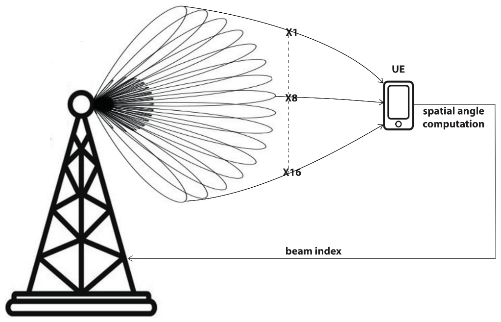
2.1. Beamforming and M-MIMO

Beamforming and M-MIMO are key technologies in the design of 5G and 6G wireless networks. They enhance network quality requirements such as reliability, signal strength and availability. Beamforming is a signal-processing technique used in antenna communication to deliver directional signals for sending or receiving data [15]. It is also known as a radio frequency management approach to control the strength of the signal in wireless communication. In beamforming, signals are focused at particular angles to achieve greater coverage for selected spatial areas or domains. This is attained by combining multiple hardware elements inside an antenna array. Beamforming provides multiple benefits in wireless communication. For instance, using spatial selectivity to focus the signal on specific direction results in a stronger signal quality, which in turn delivers data faster and reduces error occurrence. In fact, beamforming is one of the major techniques that enhances the precision of 5G networks and allows them to deliver highly reliable and effective communication capabilities.
Massive multiple-input multiple-output (M-MIMO) is another important radio technology that contributes to the quality of wireless 5G communication [16]. In M-MIMO, multiple antennas are deployed at both sides—the sender and the receiver—to enhance the throughput capacity of a radio link. M-MIMO is built upon three wireless communication technologies, which are spatial multiplexing, beamforming and spatial diversity. In radio communication, data signals might be transmitted independently in separate encoded signals or streams. Consequently, they are received with different direction of travel and different time delays. Therefore, the M-MIMO approach utilizes the deployed antennas to receive the different streams and then mathematically combine them with other streams to enhance the quality of the transmitted signal. In fact, it can be said that M-MIMO provides two main benefits, which are improved wireless coverage and increased network capacity.

2.2. Challenges in 5G and 6G Development

Although beamforming and M-MIMO are considered as key enabling technologies in 5G and 6G networks, they still encounter significant challenges due to environmental aspects. For instance, consider beamforming, which is an approach to leverage communication signals through targeting the beam at a device or group of devices that are in the line of sight of a BS. This means that antennas in both devices and BSs must be designed to cope with the complexity of aiming a beam at a specific cellular environment, including significant physical and virtual obstructions. Another challenge is verifying the strength of the beamforming signal at the physical RF antenna [17]. This is essential to validating the correctness of the beamforming weighting algorithm. Verifying the beamforming signal also contributes to validating the strength of the MIMO signal. In fact, all these challenges show the great demand for utilizing the new attachment recognition algorithm to lower the complexity of beamforming signal design.
On the other hand, M-MIMO technology still faces a set of challenges. For example, those challenges start from the deployment of M-MIMO technology. This is because M-MIMO requires large-scale architectures (i.e., large equipment, larger-sized towers). This in turn imposes further regulation since the setting of M-MIMO requires special physical arrangements. Another major issue is pilot contamination, which is the case that arises when the set of nonorthogonal pilot sequences from nearby cells overlap with each other [18]. Furthermore, estimating the accurate channels in the M-MIMO is a challenge even with the time division duplexing. This is due to the large number of antennas and to the complexity of the estimation process.

3. Edge Intelligence and 5G Networks in RESs

This section describes the importance of edge intelligence (hereafter interchangeably referred to as edge computing) in addressing several issues in 5G networks. It also describes the potentials and challenges of adopting 5G networks in distributed RESs.

3.1. Edge Computing

Edge computing is a computational paradigm that promises to address several challenges that are currently being faced by cloud-based systems. Systems that are based on the cloud computing paradigm have continuously encountered challenges such as latency and scalability [19]. This is due to the nature of the paradigm. To illustrate, the cloud computing concept is based on delivering multiple services (e.g., computation, storage) using communication networks. This means that data are moved from the source to the cloud for processing, analysis and storage. Consequently, latency arises, causing a significant issue since moving the data from sources is subject to routing, queuing and interference. Scalability is also another issue since the probability of bottleneck occurrence increases as the number of data sources increases. Given the aforementioned challenges, edge intelligence aims at addressing those issues by bringing computation and decision making closer to the edge of the network.
Edge intelligence greatly contribute to addressing multiple issues in IoT applications and distributed systems. This is because data analysis and decision making are performed within the application domain, which enhances systems’ quality, including reliability, latency and efficiency. Fifth generation networks significantly contribute to the evolution of edge intelligence. This is due to the unique characteristics of 5G networks, which were not considered in previous network generations. For instance, 5G networks are designed to deal with the massive amount of data generated from a significantly large number of devices. Additionally, 5G networks are constructed with great consideration of the heterogeneity of the environments, applications and devices [20].
Fifth generation networks inherently support the utilization of the quality of service (QoS), which is imposed by the nature of highly interactive systems. Fifth generation networks also provide extensive support to wireless-based devices (e.g., sensors, monitors), which are widely adopted in multiple distributed systems. On the other hand, edge computing contributes to the evolution of 5G networks. This is because network equipment can use intelligence techniques and algorithms to autonomously improve systems’ quality. For example, BS can use intelligence algorithms to manage network and deliver optimized coverage. In fact, 5G networks promise to deliver improved connectivity, and in turn edge computing promises to deliver intelligence. Consequently, combining these two approaches allows systems to operate and execute low-level decisions in an autonomous manner.

3.2. 5G Networks in Distributed RESs

RESs greatly depend on the connectivity of the supply side with the demand side to efficiently manage power generation and consumption. 5G wireless communication is considered as a suitable technology to connect different devices and equipment in RESs [21]. This is mainly due to the nature of the utilized devices in RESs (e.g., smart meters, sensors, UE) since they inherently support wireless communication [22]. Fifth generation communication technology provides multiple benefits for distributed RESs. For example, 5G networks have the ability to deliver high throughput even with the large number of connected devices and equipment. Additionally, 5G technology provides ultra-low latency, which is a key aspect in connecting smart devices with decision systems in distributed RESs. Furthermore, due to the nature of distributed RESs and since they are implemented in rugged terrain, which makes them subject to interference, 5G networks provide high reliability and data redundancy to ensure the delivery of data.
Distributed RESs depend heavily on connecting different devices, domains and equipment [23]. Different applications within RESs require the communication system to cope with high demand of transfer. Multiple domains within RESs contain several types of equipment. They are covered by different types of network cells such as macrocell, microcell, remote radio head (RRH) or femto base station (FBS). These cells form intra-networks within RES communication systems. The collection of those heterogeneous networks is known as HetNet [24]. Figure 1 shows an example of HetNet, where multiple systems, devices and equipment items communicate using different 5G network cells. The figure shows that data can flow top-down (e.g., from a control center to filed equipment and devices), or bottom-up (e.g., from aggregation and data acquisition systems to control systems). The figure also shows that produced energy can flow in a bidirectional manner from generation to consumer and vice versa.
Given the above discussion, it is seen that 5G wireless technology greatly improves connectivity in distributed RESs. It is also seen that the management of the different types of network cells becomes significantly complex. One of the major issues that need to be addressed in order to realize the full potentials of 5G wireless technology is interference management. This is due to the uncoordinated and unpredictable nature of HetNet in RESs. To illustrate, there is a massive growth in adopting UE in distributed RESs [21]. This means that UE items are periodically introduced and removed from distributed RESs, which makes interference management not only a complex task, but also contentious. Therefore, optimized beam-attachment approaches are required to ease network management. Additionally, different UE items generate significant and unpredicted data traffic. In turn, the communication system needs to deal with this unpredictability and provide the reacquired load management and coverage.

4. Related Work

This section presents some of the literature works. It covers two research domains. The first one is the beam management for 5G communication using Artificial Intelligence (AI) techniques. The second one is the implementation of 5G wireless communication in applications such as smart grids and distributed RESs.
The application of AI techniques including machine learning (ML) techniques in wireless systems has received considerable interest in recent years. They are first used for the 5G deployment and it is expected that they will be implemented at the UE level. AI techniques can be used to help the coordination between the BS and UE to speed up decisions based on models built using training sets. Those will improve the system’s performance in terms of throughput and reliability.
In [25], the authors proposed a deep-learning-based beam management and interference coordination, where the direction width and transmit power for each beam are simultaneously optimized. In [26], the authors showed that learning-based beam training can offer low latency and higher throughput compared to the conventional methods based on exhaustive beam search, where the environments can be learned with consideration of blockage. Here, parameters including blockage or channel correlation of a UE can be exchanged between BSs and/or reported by the UE. In [27], the authors designed online learning algorithms for beam pair selection and refinement using a multi-armed bandit framework. It allows the update of the database by including new observations during the beam-tracking process. In [28], a machine learning technique is developed to correctly recognize the future channel state information (CSI) based on the previous CSI.
Due to advances in 5G technology, mobile cellular networks have been widely proposed to be adopted in smart grids and RESs. The work in [21] shows the advantages and the potentials of adopting 5G technology in smart grids. The authors show how 5G networks improve machine-type communications. They also present the concept of adopting edge computing to improve 5G communication in smart grids and their applications. The authors focus on showing how decision making is improved when using 5G-enabled applications. They present the use of 5G networks in applications such as state estimation systems and power distributed optimization. They also provide a study on integrating smart grids and their applications with improved wireless technologies.
The work by Carrillo et al. [17] also shows the benefits of adopting 5G technology in smart grid communication. In particular, the work focuses on the impact of 5G networks on the management of communication in different domains in a smart grid. It shows radio access network slicing can address the communication interoperability issues that are faced by smart grids. The authors provide a radio access slicing framework based on artificial intelligence to support communication in field devices and equipment. The slicing framework is used to create different communication environments to address the heterogeneity of different services and data in smart grids. As a result, the research outcomes show the advantages of adopting 5G networks in smart grids.
Given the above reviews, our work in this paper provides a low-complexity approach to improving beam management and multiuser scheduling through modeling of the mapping between UE geolocation and its serving beam in one of the main applications in smart grids, i.e., RESs. More specifically, it aims to predict the beam-attachment index in 5G wireless networks that is adopted in RESs. Our work focuses on RESs as a domain of research since they are distributed in nature and also since the communication behavior in RESs is unpredictable due to factors such as interference and wireless signal fading.

5. System Model

This section describes the communication system model. The model in this work follows an approach similar to the system model defined in [29]. However, the application of wireless communication in this work is intended for a different environment. It simulates 5G communication in a dense and flexible distributed RES environment. It is worth mentioning that this system model can be seen as a common model since 5G networks follow similar communication behavior. In this section, we also illustrate the assumptions in this work. Both the system model and assumptions are designed to represent a real-world 5G wireless network that is deployed in a distributed RES environment.

5.1. Considered Model and Assumptions

The system model is designed to simulate the real-world development of the 5G Macrocell Base Station (MBS). The assumption is that this MBS is deployed in a densely distributed RES environment. The model represents a hexagonal network which consists of two adjacent macrocells m c , c = 1 , 2 . The represented BS c in the model employs an M-MIMO system with fixed GoBs. It is denoted by B BS c , in the downlink (DL) as in [29]. For each BS in the system, a specific number of antenna Vertical Dipole Array is defined. The number is assumed as BS c , a N x × N z (sub). Additionally, a defined distance is provided for a square metallic conductor, and it is λ 2 . In this definition, λ represents the wavelength and N x = N z = 16 . Therefore, the narrowest beams are produced by the antenna array. Based on this definition, the radiation patterns are coupled with the radiating elements. This means changes are applied to the radiation patterns only based on the type of radiating elements. To simplify the model, an infinite perfect electrical conductor (PEC) is used in the approximation process for the utilized reflector. Hence, N x ( N z ) elements are defined for each row (column) and they are equidistant with a spacing of d x ( d z ). It is worth mentioning that this work can be generalized to include more than two cells to cover larger and more heterogenous cell environments.
One of the main concepts in modeling beam-attachment maps is determining the angle of a beam direction. In this model, the direction is specified by the angle θ b , ϕ b in circular coordinations that are defined by θ and ϕ . The accumulated reception for an antenna in a BS c for a given user u c is channeled to θ u c , ϕ u c . This reception gain is attached to the beam b u c and it is defined by θ b u c , ϕ b u c . The total antennal gain in the above-described user is given as:
g b u c BS c θ u c , ϕ u c , θ b u c , ϕ b u c = g 0 f θ u c , ϕ u c , θ b u c , ϕ b u c ,
where g 0 represents the maximum gain in the following direction θ b u c , ϕ b u c . On the other hand, f ( . ) represents a function that describes a normalized gain. Additionally, a separable f is assumed with excitation in the x and z directions. The resulting form of f is given as:
f θ u c , ϕ u c , θ b u c , ϕ b u c = A F x θ u c , θ b u c , ϕ u c , ϕ b u c · A F y θ u c , ϕ u c · A F z θ u c , θ b u c 2 · g d θ u c
where A F x θ u c , θ b u c , ϕ u c , ϕ b u c and A F z θ u c , θ b u c are the array factors in the x and z directions and are given by:
A F x θ u c , θ b u c , ϕ u c , ϕ b u c = 1 N x sin N x 2 ψ x sin 1 2 ψ x ,
and
A F z θ u c , θ b u c = 1 N z sin N z 2 ψ z sin 1 2 ψ z ,
where
ψ x = 2 π d x sin θ u c sin ϕ u c sin θ b u c sin ϕ b u c ,
ψ z = 2 π d z cos θ u c cos θ b u c .
Another important aspect in modeling antenna is realizing the PEC impact. The shapes of radiating elements that are created by PEC can be used to describe its impact. A F y θ u c , ϕ u c considers the shapes of the radiating elements, where it is defined as:
A F y θ u c , ϕ u c = sin π 2 sin θ u c cos ϕ u c ,
Given the above term definition, the pattern of the normalized gain of the dipoles g d θ u c is approximated as:
g d θ = sin 3 θ u c .
The power conservation equation that defines the term g 0 is given as follows:
g 0 = 4 π π 2 π 2 0 π f θ u c , ϕ u c , θ b u c , ϕ b u c sin θ u c d θ u c d ϕ u c .
Based on the above definitions, a beam is defined as sub-array rectangular size and its direction is defined by θ b u c , ϕ b u c .

5.2. Connection Procedures

Before the data-connection phase, each BS c needs to search the suitable serving beam for each UE. This searching procedure is made in the initial access phase. In fact, BS c sends multiple beamformed Channel State Information Reference Signals (CSI-RSs). These CSI-RSs are used to acquire the spatial angle between BS c and UE as shown in Figure 2. Assuming that the number of CSI-RSs is N B , then W is defined as W = w 1 , , w k , , w N B , where w k is the precoding weight of the k-th beam. Given that UE selects and feeds back to BS the best beam index among the N B beams. The best beam is chosen to maximize the received power. It is also utilized to enhance the corresponding Channel Quality Indicator (CQI).
In case of dual-polarized antennas, it is additionally required to feed back co-phase information to adapt the channel orthogonalization between layers. Upon the receipt of the beam index by the BS c , the weight assigned to the selected beam is employed for data transmission. Based on the described connection procedure, u is utilized to denote the useful signal received power by a given UE. The location of u is denoted by l u . The beam that is attached to u ( b u B m ) in a location is defined as linear scale, and written as:
C m b u l u = P m · ς D m κ l u · G m b u l u · F l u · S l u ,
where P m is the transmit power of m. Additionally, ς is considered as a constant. The value of this constant is defined by the environment and it is based on the carrier wavelength. D m l u represents a connection distance. In particular, this distance represents the length between u and m. In this distance, κ specifies the path-loss exponent. G m b u l u represents the gained beam at the antenna b u which serves u that is defined in a location l u . F l u defines the fast fading term. Its value is essential and it is used for modeling residual multipaths which are due to reflections from surrounding buildings. The last parameter in the equation is S l u and it represents the log-normal shadowing. This parameter provides effect measurements since it considers environmental obstacles between m and u.
Figure 3 presents the Reference Signal Received Power (RSRP) in an area that is covered by two interfered-with cells with a resolution of 1 m × 1 m . This resolution choice can be justified by the fact that the localization accuracy is around one meter for 5G outdoor applications [30]. It can also be justified since we consider applying 5G wireless communication in a distributed RES environment where beams’ radiated power is densely interfered with. This radio environment map is constructed based on real-world 5G interfered cells. Equation (10) is used to generate the illustrated radio map based on the above defined resolution parameters. In the figure, the X axis and the Y axis show the distribution of the radiated power of all considered beams. The boresight (i.e., the axis of maximum radiated power) of the antenna is shown in the right of the figure.
To maintain a good connection with the best beam, UE must periodically measure the RSRP. Consequently, a considerable time should be dedicated to the beam-attachment phase. Typically, this is a complex task and its efficiency depends heavily on the utilized algorithm. Given that, the purpose of this work is to propose a low-complexity algorithm based on machine learning techniques. The aim is to automatically recognize the best beam index for a given UE through its location. In the following, we present our proposed beam-attachment index-recognition approach.

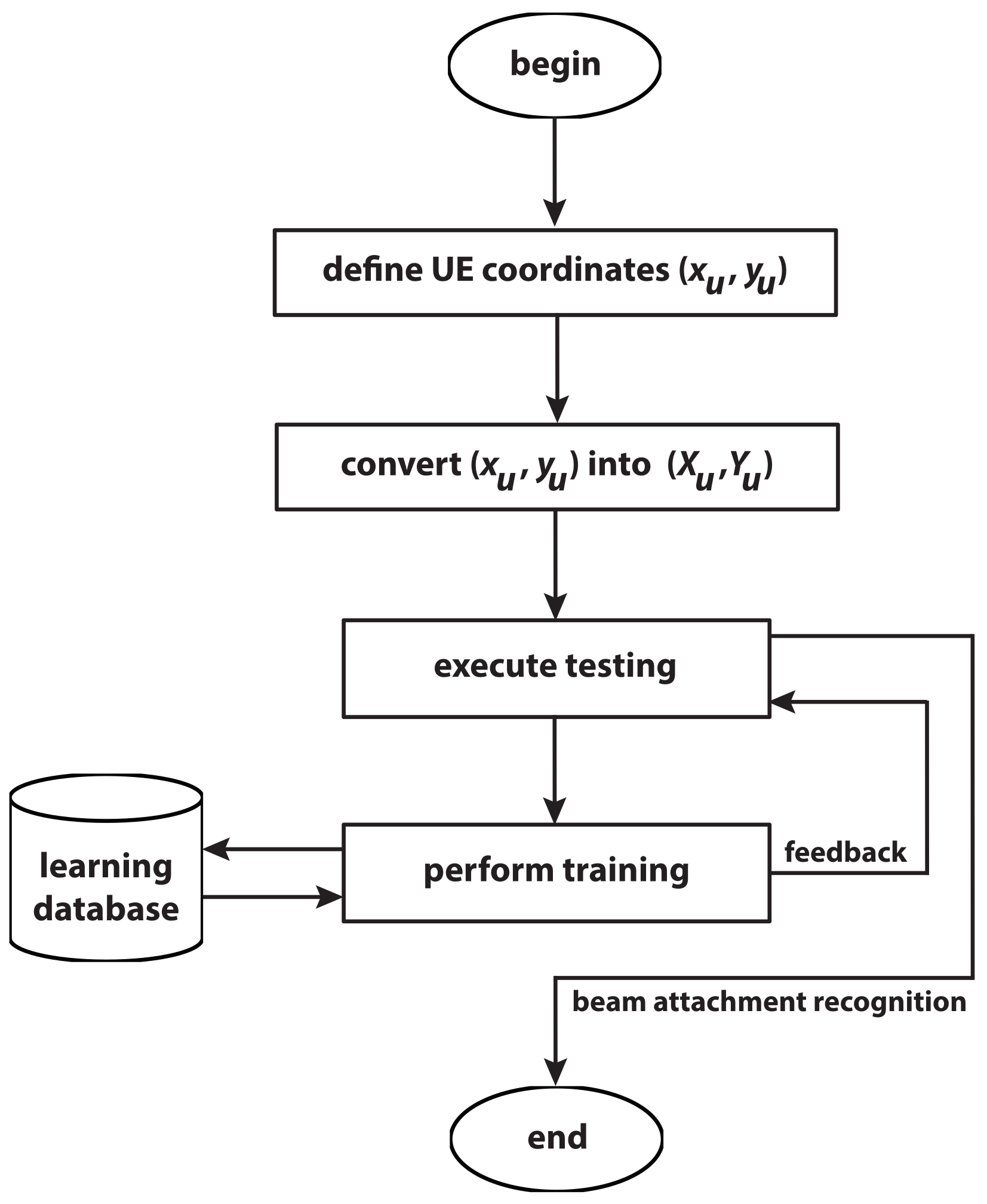
6. Beam-Attachment Index Recognition

This section describes the proposed beam-attachment-recognition mechanism. It also illustrates the comparative study that is carried out in this work. It defines the types of algorithms and classifications. In the approach use cases from distributed RESs are used.

6.1. Definitions and Approach

As described in Section 3, distributed RESs consist of a wide range of communicating equipment and devices. The communicating entities in an RES environment are periodically added and removed. Therefore, the wireless communication system must provide a flexible approach to recognize each UE within the communication range. Additionally, the approach should not introduce complexity into the system. It should also provide precise beam-attachment recognition. Given that, the following describes a low-complexity algorithm to recognize a beam-attachment index for a UE (denoted u) and located at l u . The algorithm utilizes edge intelligence techniques to improve the efficiency of beam attachment for a given UE. It is based on location key features given as ( x u , y u ) .
In this work, we consider a non-standalone 5G NR which are commonly implemented and proposed in smart grids and RESs [31]. The Long-Term Evolution (LTE) Positioning Protocol (LPP) is used in this non-standalone 5G NR to facilitate communication between the core network and UE. The exchanged data represent UE side information that is distributed to different all gNodeB (gNBs) (i.e., a 5G BS NR). The geolocation information that is exchanged in the network for u, l u , represents the two-dimensional vector including the absolute latitude and longitude information. It can be defined as:
l u = x u , y u
where x u and y u are the latitude and longitude coordinates, respectively. Note that we need to convert from longitude and latitude x u , y u to native map projection X u , Y u .
Figure 4 shows the flowchart of the proposed beam-attachment-recognition approach. It describes the attachment technique of a given location for a UE. As shown from the figure, the first phase is collecting the UE coordinates using LPP. This is essential since it provides side information from UE. Once the UE coordinates are specified, they are converted into native map projection coordinates. This provides a comprehensive view of the network and enhances the corresponding UE location in the considered environment. Given that, a training phase is then established. This later phase involves building a classifier from a learning database (DB). Thereafter, the test phase is performed to recognize the beam-attachment index based on the built classifier. It is seen from the figure that the definition phase requires only two features for each UE, which are the coordinates x u , y u . Similarly, the conversion phase results in the same number of features (i.e., coordinates to native map projection). This shows that the proposed algorithm in this work simplifies not only the computation process but also memory and processing requirements. In fact, several positioning algorithms such as the ones proposed in [32,33,34] require multiple environmental features, which produces quality positioning results. However, this induces complexity in terms of computation, memory requirements and training requirements.

6.2. Classifiers Comparison

Different specific classifiers can be used to implement the above-described beam-attachment recognition approach. Therefore, multiple classification algorithms (i.e., K-Nearest Neighbors (KNN), Decision Tree, Support Vector Machines and KStar) have been considered. Based on the attributes of each classifier and given the initial performed tests, KStar and KNN are chosen in this work. Several extensive tests are performed to observe different aspects such as the classifier’s true positive and false positive rates. Given the results of the tests, we carry out a comparative analysis according to the defined metrics for both KStar and KNN. The objective of this comparative study is to specify the best classifier to be implemented in the recognition approach in this work.
KStar and KNN have unique attributes in terms of classifications, sorting and directed search. For example, KStar has the ability to operate on the fly. This means that the sorting graph does not need to be entirely in the main memory before the sorting process starts [35]. This enhances execution time as well as memory utilization. Additionally, KStar facilitates the optimized classification process since it can be guided by heuristic functions. Similarly, KNN provides several advantages over other classification methods. KNN is an instance-based learning method, which means it does not require a training period [36]. This allows for adding new data in a seamless manner without affecting the performance or accuracy of an algorithm. Given these advantages, it is concluded that KStar and KNN are suitable for the classification process in wireless environments.

6.2.1. KStar Classifier

The KStar algorithm is considered an instance-based classifier. Using the algorithm, the test set containing the projected coordinates of N UE will be divided into K clusters. Here, KStar employs the entropic distance measurement to compute the distance among instances. Then, this entropic distance will be used for retrieving the most similar instances from the dataset. Thereafter, the projected coordinates of the considered N UE will be attached to the most expected beam-attachment index, B e a m m , where m = 1 , , K . The KStar probability is expressed as:
K * B e a m m , ( X u , Y u ) = ln P * B e a m m , ( X u , Y u ) .
Based on the above-defined probability, there are multiple paths for reaching a beam. The probability of given coordinates ( X u , Y u ) that might reach to B e a m m via a random path is given by P * . This definition has multiple benefits. For example, it allows handling the missing values. It also deals with real-value and symbolic attributes in the recognition process.

6.2.2. KNN Classifier

KNN classifier is an effective approach belonging to a lazy learning category. With this technique, a majority vote is performed to assign new UE coordinates to the B e a m m with the highest similarity. In this approach, the distance is the key factor to identify the similarity between two projected coordinates. For instance, assume there are multiple pairs F 1 , B e a m 1 , , F L , B e a m L where F i = ( X i , Y i ) R 2 and B e a m i 0 , 1 , , K for a new i. In this case, KNN uses the majority vote to identity the nearest beam. In this work, we use the Euclidean distance in KNN to identify the similarity between two vectors. It is given by:
d F i , F j = F i F j 2 = k = 1 2 F i k F j k 2
where F i , F j R 2 , F i = F i 1 , F i 2 = X i , Y i .

6.2.3. Classifier Performance Evaluation

Based on the above definitions, we evaluate the classifiers using a set of metrics. We compare the performance of KNN and KStar and we show their performance using a dataset with real beam-attachment indexes. The metrics are given and identified in the context of this work as follows:
  • True Positive Rate (TPR).
  • False Positive Rate (FPR).
  • Precision.
  • F-Measure.
Given the above description of the utilized metrics, Equation (14) identifies the precision metric, Equation (15) identifies the recall metric and Equation (16) identifies the F-measure metric.
Precision = TPR TPR + FPR ,
Recall = TPR TPR + FN ,
F - measure = 2 × precision × recall precision + recall .

7. Simulation and Evaluation

In this section, we describe the settings of the performed experiments. We illustrate the results of the comparative study to measure the performance of KNN against KStar. We also systematically show the effectiveness of our approach by testing it with different learning sets.

7.1. Setup and Parameters of Experiments

In this section, we show the simulation results and we test the viability of the proposed approach in this work. To perform the simulation, we consider the two neighboring BSs with the M-MIMO deployment that is described in Section 5. The setting of the performed experiment simulates BSs that are deployed in RESs. The neighboring BSs are intended to connect the power-generation domain with the consumption domain. To bring the simulation closer to the real RES environment, we consider the wireless network parameters. We also consider the characteristics of the communication channels within the wireless network. In fact, combining network parameters with channel characteristics yields precise results that describe real BS settings in real RES environments. This combination also provides significant insights about the expected behavior of the communication channels.
The simulation parameters for the network are listed in Table 1. Those parameters describe the type of communication traffic that is allowed based on the given setting in the table. On the other hand, Table 2 illustrates the channel characteristics. The table describes the behavior of the traffic in the performed experiments. The parameters in Table 1 and Table 2 are designed to simulate real HetNets wireless communication environments as described in [37,38,39]. Several simulation tests are carried out to highlight the benefits of the recognition approach for identifying beam-attachment indexes. A large dataset containing 640,000 beam-attachment indexes is used. This dataset represents a uniform grid in real-world wireless environment settings. The grid is generated from 800 m × 800 m locations. The resolution of the provided uniform grid is 1 m × 1 m . Given the description in Section 6, a training phase is carried out once data are collected and converted. In this phase, the training set is first built for each beam index based on 10 % extraction from the whole dataset. Based on that, we compare the performance of the classifiers that are described in Section 6.

7.2. Classifier Evaluation

Based on the defined approach in Section 6, multiple experiments are carried out. The objective of those tests is to evaluate the performance of KNN compared to KStar. In the experiment, a 10-fold cross-validation training and testing approach is used. In this cross-validation, we investigate generalizing the training outcomes to an independent subset. The training is carried out using the dataset described in the above section. The aim of the overall experiment is to test the ability of the proposed approach to correctly estimate the performance of the model. Given that, the above-described metrics (TPR, FPR, precision, recall, and F-measure) are used.
The metrics are used on a learning set with 10% of extraction. The average result of each presented metric is used to compare the performance of KNN against KStar. Table 3 presents the results of the performed tests for each classifier using the defined metrics. With regard to beam-attachment recognition, it is clearly seen from the average of the presented results that KNN outperforms KStar. To illustrate, with KNN, higher values are obtained with TPR, precision, recall, and F-measure than KStar. On the other hand, FPR of KNN is lower than KStar. Therefore, it is concluded that in this work we adopt KNN for beam-attachment recognition. Subsequently, KNN is also used to generate beam-attachment maps in the later experiments.

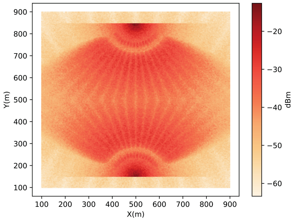
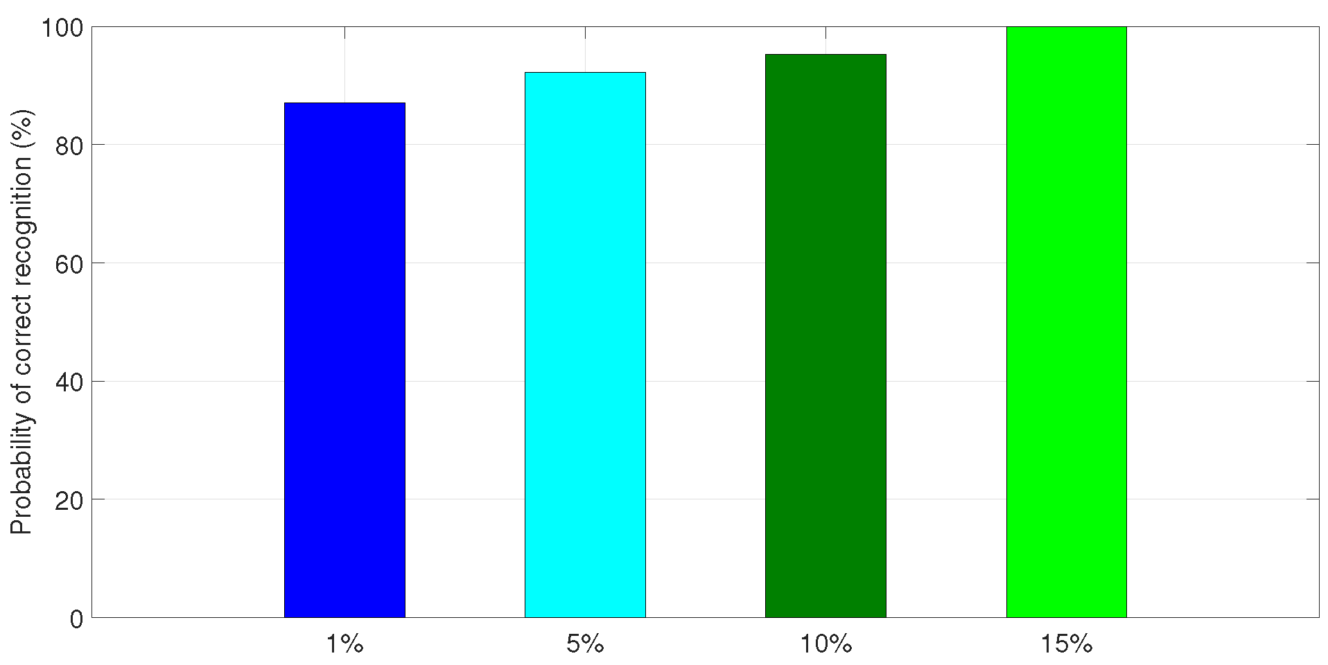
7.3. Recognition of Beam-Attachment Map

In the following experiments, we use the proposed approach to generate a beam-attachment map. The purpose of comparing beam-attachment maps is to determine the ability of the approach in recognizing precise maps. Additionally, the comparison provides insights into the required learning dataset’s size and time.
Figure 5 presents the real beam-attachment map over the geographic area of interest in this work. The presented map is generated based on the dataset described in Section 7.1. This map is compared to the model generated in Figure 3, which is generated with a resolution of 1 m × 1 m . Based on this comparison, it is decided that the map in Figure 5 is used as the target model (i.e., benchmark in the subsequent model generation). Thus, the following presents a systematic investigation process with different extraction sizes. In this process, we test the impact of increasing the size of the learning sets. We also observe the optimal learning set size by comparing the results to the target model.
Multiple experiments are executed with different extraction size. For each size, we test the ability of the learning approach in determining beam-attachment recognition maps. Based on that, we compare the results with the real beam attachment over the specified geographic area. Figure 6 shows the plotted learning set and the predicted beam-attachment map using a learning set with 1 % of extraction from the original dataset. The figure shows that the initial map begins to appear with considerable map noise and uncertainty. Nevertheless, the overall map of beam attachment is clearly seen.
Figure 7 shows the constructed beam-attachment map using different learning sets. Graph (a) shows the results with the sub-set that consists of 5 % extraction of the whole dataset. Graph (b) shows the results with 10 % extraction of the entire dataset. As seen from both graphs, the constructed maps contain errors in the cell-edge zone and beam borders as the learning set size is small. However, as the extraction size grows, the accuracy of the constructed map increases. This indicates that the proposed approach shows promising results even with little increase in the extracted sub-sets.
The accuracy of the proposed beam-attachment approach is clearly seen in Figure 8. Graph (a) shows the constructed beam-attachment map with 15 % of extraction from the whole dataset. On the other hand, graph (b) shows the target map (i.e., benchmark map) that is generated in Figure 5. It is seen from both graphs that the proposed approach generated a beam-attachment map that is identical to the target map with only 15 % of extraction of the entire dataset. This means that it can be said that the approach reaches accurate recognition (around 100 % ) with low data extraction. This indicates that the proposed approach has the ability to generate promising reconstruction quality even with a small density of data measurements. It also shows that results are produced with low complexity since only 15 % of extraction is enough to construct the target map. In fact, the approach shows optimized performance since reconstructing the target map requires less resources and time. Finally, Figure 9 summarizes the performance on the approach when increasing the size of the learning set.
It is seen from the above-generated maps that the proposed approach in this work provides highly accurate beam-attachment recognition. The approach also does not introduce any complexity to the system. It also requires less time and minimal dataset size to produce beam-attachment maps. In fact, it reaches about 100 % accuracy in predicting beam recognition with only 15 % of the learning set. Given these results, the approach can greatly improve 5G wireless communication in RESs. That is because it has the ability to efficiently discover new introduced UE in an RES environments. The approach can especially improve communication with mobile UE in RESs such as electrical vehicles and mobile smart meters. Overall, it can be said that this approach provides efficiency and accuracy and it lowers learning complexity, which improves 5G network coverage.

7.4. Discussion

Given the above results, we compare the approach with similar works. As mentioned above, to the best of our knowledge, no work has used the lazy learning approach to identify the beam attachment in a predictive manner. Multiple works have used training approaches to optimize the process of locating a user in 5G networks. For instance, [32] proposed an approach to locate users based on their uplink RSS. The authors used an analytical moment matching based on Gaussian process regression. The approach has shown promising results in locating users within an area of interest. However, in the training phase their approach requires one to utilize a significant number of features from the datasets. Additionally, unlike our proposed approach, the complexity of their method increases in the cubic order with the number of training datasets.
Similarly, [33] proposed a location-based method to identify users in a specific area. A data-generation method is first proposed. Then, they use a deep learning positioning method that is trained on the generated dataset. The approach requires significant feature extractions. This increases the complexity of the approach and restricts the approach in terms of considering extra data on-the-fly. This is mainly since the approach requires all features to be extracted and identified prior to the training phase. Although the above approaches provide promising predictive location services, they introduce significant complexity in terms of feature extraction and required datasets and training. In fact, our approach produced accurate beam-attachment maps (around 100%) with only 15% of extraction of the dataset and only two feature types.

8. Conclusions

In this work, we presented a low-complexity approach to optimizing 5G beam-attachment recognition in a distributed RES environment. We also presented the benefits and the challenges that face the 5G wireless networks in RESs. In the approach, we first define the system model. The model is designed to simulate a real-world 5G network that is deployed in RESs. We then describe the assumptions and the connection procedures to represent wireless communication in a densely distributed RES environment. Given that, we defined the beam-attachment recognition for UE in RESs. The proposed approach depends on utilizing the coordinates of UE and converting them into a native map to provide a comprehensive view of the beam-attachment map. Based on that, we use the lazy learning approach to train the algorithm to recognize the beam-attachment index at each location in the area of interest. We test the approach using a dataset containing beam-attachment indexes. The results prove that the proposed approach has the ability to produce precise identification of a beam-attachment index with a minimal amount of recognition training. In future work, we plan to study the generalization of the approach to include different application domains. We also plan to investigate the viability of the approach with a 6G network.

Funding

This research was funded by the Deputyship for Research & Innovation, Ministry of Education in Saudi Arabia through the project number 223202.

Institutional Review Board Statement

Not applicable.

Informed Consent Statement

Not applicable.

Data Availability Statement

Not applicable.

Acknowledgments

The authors extend their appreciation to the Deputyship for Research & Innovation, Ministry of Education in Saudi Arabia for funding this research work through the project number 223202.

Conflicts of Interest

The authors declare that there were no disclosed possible conflict of interest relevant to the research.

References

  1. Andreev, S.; Galinina, O.; Pyattaev, A.; Gerasimenko, M.; Tirronen, T.; Torsner, J.; Sachs, J.; Dohler, M.; Koucheryavy, Y. Understanding the IoT connectivity landscape: A contemporary M2M radio technology roadmap. IEEE Commun. Mag. 2015, 53, 32–40. [Google Scholar] [CrossRef]
  2. Firouzi, R.; Rahmani, R. 5G-Enabled Distributed Intelligence Based on O-RAN for Distributed IoT Systems. Sensors 2022, 23, 133. [Google Scholar] [CrossRef]
  3. Rinaldi, F.; Raschella, A.; Pizzi, S. 5G NR system design: A concise survey of key features and capabilities. Wirel. Netw. 2021, 27, 5173–5188. [Google Scholar] [CrossRef]
  4. Tipantuña, C.; Hesselbach, X. Adaptive energy management in 5G network slicing: Requirements, architecture and strategies. Energies 2020, 13, 3984. [Google Scholar] [CrossRef]
  5. Dragičević, T.; Siano, P.; Prabaharan, S.S. Future generation 5G wireless networks for smart grid: A comprehensive review. Energies 2019, 12, 2140. [Google Scholar]
  6. Kabalci, Y. 5G mobile communication systems: Fundamentals, challenges and key technologies. In Smart Grids and Their Communication Systems; Springer: Singapore, 2018; pp. 329–359. [Google Scholar]
  7. Valtanen, K.; Backman, J.; Yrjölä, S. Blockchain-powered value creation in the 5G and smart grid use cases. IEEE Access 2019, 7, 25690–25707. [Google Scholar] [CrossRef]
  8. Letaief, K.B.; Shi, Y.; Lu, J.; Lu, J. Edge artificial intelligence for 6G: Vision, enabling technologies, and applications. IEEE J. Sel. Areas Commun. 2021, 40, 5–36. [Google Scholar] [CrossRef]
  9. Rong, B. 6G: The next horizon: From connected people and things to connected intelligence. IEEE Wirel. Commun. 2021, 28, 8. [Google Scholar] [CrossRef]
  10. Shi, Y.; Yang, K.; Jiang, T.; Zhang, J.; Letaief, K.B. Communication-efficient edge AI: Algorithms and systems. IEEE Commun. Surv. Tutor. 2020, 22, 2167–2191. [Google Scholar] [CrossRef]
  11. Yang, K.; Jiang, T.; Shi, Y.; Ding, Z. Federated learning via over-the-air computation. IEEE Trans. Wirel. Commun. 2020, 19, 2022–2035. [Google Scholar] [CrossRef]
  12. Chikha, H.B.; Almadhor, A.; Khalid, W. Machine learning for 5G MIMO modulation detection. Sensors 2021, 21, 1556. [Google Scholar] [CrossRef]
  13. Ben Chikha, W.; Chaoui, S.; Attia, R. Identification of superposed modulations for two-way relaying MIMO systems with physical-layer network coding. IET Commun. 2017, 11, 225–231. [Google Scholar] [CrossRef]
  14. Roth, J.D.; Tummala, M.; McEachen, J.C. Efficient system geolocation architecture in next-generation cellular networks. IEEE Syst. J. 2017, 12, 3414–3425. [Google Scholar] [CrossRef]
  15. Zhai, X.; Chen, X.; Xu, J.; Ng, D.W.K. Hybrid beamforming for massive MIMO over-the-air computation. IEEE Trans. Commun. 2021, 69, 2737–2751. [Google Scholar] [CrossRef]
  16. Zhu, G.; Huang, K. MIMO over-the-air computation for high-mobility multimodal sensing. IEEE Internet Things J. 2018, 6, 6089–6103. [Google Scholar] [CrossRef]
  17. Carrillo, D.; Kalalas, C.; Raussi, P.; Michalopoulos, D.S.; Rodríguez, D.Z.; Kokkoniemi-Tarkkanen, H.; Ahola, K.; Nardelli, P.H.; Fraidenraich, G.; Popovski, P. Boosting 5G on smart grid communication: A smart RAN slicing approach. IEEE Wirel. Commun. 2022. [Google Scholar] [CrossRef]
  18. Björnson, E.; Hoydis, J.; Sanguinetti, L. Pilot contamination is not a fundamental asymptotic limitation in massive MIMO. In Proceedings of the 2017 IEEE International Conference on Communications (ICC), Paris, France, 21–25 May 2017; pp. 1–6. [Google Scholar]
  19. Haibeh, L.A.; Yagoub, M.C.; Jarray, A. A survey on mobile edge computing infrastructure: Design, resource management and optimization approaches. IEEE Access 2022, 10, 27591–27610. [Google Scholar] [CrossRef]
  20. López-Pérez, D.; De Domenico, A.; Piovesan, N.; Xinli, G.; Bao, H.; Qitao, S.; Debbah, M. A survey on 5G radio access network energy efficiency: Massive MIMO, lean carrier design, sleep modes and machine learning. IEEE Commun. Surv. Tutor. 2022, 24, 653–697. [Google Scholar] [CrossRef]
  21. Cosovic, M.; Tsitsimelis, A.; Vukobratovic, D.; Matamoros, J.; Anton-Haro, C. 5G mobile cellular networks: Enabling distributed state estimation for smart grids. IEEE Commun. Mag. 2017, 55, 62–69. [Google Scholar] [CrossRef]
  22. Alaerjan, A. Towards Sustainable Distributed Sensor Networks: An Approach for Addressing Power Limitation Issues in WSNs. Sensors 2023, 23, 975. [Google Scholar] [CrossRef]
  23. Alaerjan, A.S. Model-driven interoperability layer for normalized connectivity across smart grid domains. IEEE Access 2021, 9, 98639–98653. [Google Scholar] [CrossRef]
  24. Alhashimi, H.F.; Hindia, M.N.; Dimyati, K.; Hanafi, E.B.; Safie, N.; Qamar, F.; Azrin, K.; Nguyen, Q.N. A Survey on Resource Management for 6G Heterogeneous Networks: Current Research, Future Trends and Challenges. Electronics 2023, 12, 647. [Google Scholar] [CrossRef]
  25. Zhou, P.; Fang, X.; Wang, X.; Long, Y.; He, R.; Han, X. Deep learning-based beam management and interference coordination in dense mmWave networks. IEEE Trans. Veh. Technol. 2018, 68, 592–603. [Google Scholar] [CrossRef]
  26. Chang, T.W.; Shen, L.H.; Feng, K.T. Learning-based beam training algorithms for IEEE802. 11ad/ay networks. In Proceedings of the 2019 IEEE 89th Vehicular Technology Conference (VTC2019-Spring), Kuala Lumpur, Malaysia, 28 April 2019–1 May 2019; pp. 1–5. [Google Scholar]
  27. Va, V.; Shimizu, T.; Bansal, G.; Heath, R.W. Online learning for position-aided millimeter wave beam training. IEEE Access 2019, 7, 30507–30526. [Google Scholar] [CrossRef]
  28. Guo, Y.; Wang, Z.; Li, M.; Liu, Q. Machine learning based mmWave channel tracking in vehicular scenario. In Proceedings of the 2019 IEEE International Conference on Communications Workshops (ICC Workshops), Shanghai, China, 20–24 May 2019; pp. 1–6. [Google Scholar]
  29. Chikha, W.B.; Masson, M.; Altman, Z.; Jemaa, S.B. Radio Environment Map Based Inter-Cell Interference Coordination for Massive-MIMO Systems. IEEE Trans. Mob. Comput. 2022. [Google Scholar] [CrossRef]
  30. Bartoletti, S.; Conti, A.; Dardari, D.; Giorgetti, A.; Marsan, M.; Melazzi, N. 5G Localization and Context-Awareness. 5G Italy White Book: From Research to Market. 2018, pp. 167–187. Available online: www.5gitaly.eu (accessed on 20 January 2023).
  31. Borgaonkar, R.; Anne Tøndel, I.; Zenebe Degefa, M.; Gilje Jaatun, M. Improving smart grid security through 5G enabled IoT and edge computing. Concurr. Comput. Pract. Exp. 2021, 33, e6466. [Google Scholar] [CrossRef]
  32. Prasad, K.; Hossain, E.; Bhargava, V.; Mallick, S. Analytical approximation-based machine learning methods for user positioning in distributed massive MIMO. IEEE Access 2018, 6, 18431–18452. [Google Scholar] [CrossRef]
  33. Gao, K.; Wang, H.L.H.L.W. Towards 5G NR High-Precision Indoor Positioning via Channel Frequency Response: A New Paradigm and Dataset Generation Method. IEEE J. Sel. Areas Commun. 2022, 40, 2233–2247. [Google Scholar] [CrossRef]
  34. Prasad, K.S.V.; Hossain, E.B.V. Machine learning methods for RSS-based user positioning in distributed massive MIMO. IEEE Trans. Wirel. Commun. 2018, 17, 8402–8417. [Google Scholar] [CrossRef]
  35. Husain, A.; Stefan, L. K*: A heuristic search algorithm for finding the k shortest paths. Artif. Intell. 2011, 175, 2129–2154. [Google Scholar]
  36. Padraig, C.; Sarah, D. K-Nearest Neighbour Classifiers—A Tutorial. ACM Comput. Surv. 2021, 54, 1–25. [Google Scholar]
  37. Tall, A.; Altman, Z.; Altman, E. Virtual sectorization: Design and self-optimization. In Proceedings of the 2015 IEEE 81st Vehicular Technology Conference (VTC Spring), Glasgow, UK, 11–14 May 2015; pp. 1–5. [Google Scholar]
  38. Yin, F.; Zeng, M.; Zhang, Z.; Liu, D. Coded caching for smart grid enabled HetNets with resource allocation and energy cooperation. IEEE Trans. Veh. Technol. 2020, 69, 12058–12071. [Google Scholar] [CrossRef]
  39. Jaziri, A.; Nasri, R.; Chahed, T. Performance analysis of small cells’ deployment under imperfect traffic hotspot localization. In Proceedings of the 2015 IEEE Global Communications Conference (GLOBECOM), San Diego, CA, USA, 6–10 December 2015; pp. 1–6. [Google Scholar]
Figure 1. HetNet in RES domains with different types of devices and systems.
Sustainability 15 08863 g001
Figure 2. Beamformed CSI-RS transmission scheme.
Sustainability 15 08863 g002
Figure 3. RSRP over the geographic area covering the two adjacent cells with a resolution of 1 m × 1 m .
Sustainability 15 08863 g003
Figure 4. Beam-attachment recognition of a given location for a UE.
Sustainability 15 08863 g004
Figure 5. Real beam attachment over the geographic area of interest.
Sustainability 15 08863 g005
Figure 6. Constructed model and map with 1% extraction. (a) Learning set model. (b) Beam-attachment map.
Sustainability 15 08863 g006
Figure 7. Constructed beam-attachment maps with 5% and 10% extractions. (a) 5% extraction. (b) 10% extraction.
Sustainability 15 08863 g007
Figure 8. Comparison of constructed map with target map. (a) 15% extraction. (b) Target map.
Sustainability 15 08863 g008
Figure 9. Performance of KNN classifier using different learning sets.
Sustainability 15 08863 g009
Table 1. Network parameters.
Network ParametersValue
Number of BSs2
Number of beams N B per BS16
BS transmit power 46 dBm
Bandwidth 20 MHz
Table 2. Channel characteristics.
Channel CharacteristicsValue
Thermal noise per Hertz 174 dBm / Hz
Path loss (D in km) 128.1 + 37.6 log 10 D dB
Nakagami-m shape parameter5
Shadowing Log-normal 6 dB
Intersite distance 700 m
Table 3. KNN Vs. KStar: 10-fold cross-validation using a learning set with 10% of extraction.
TPRFPRPrecisionRecallF-MeasureClass
KNNKStarKNNKStarKNNKStarKNNKStarKNNKStar
0.9720.9760.0020.0210.9710.7450.9720.9760.9710.8451
0.9390.7520.0030.0060.9240.8410.9390.7520.9320.7942
0.9140.830.0030.0040.9170.8720.9140.830.9150.8513
0.9280.730.0030.0050.9260.8690.9280.730.9270.7944
0.9210.6380.0020.0030.9150.8370.9210.6380.9180.7245
0.9260.8940.0020.0040.9220.8320.9260.8940.9240.8626
0.9140.7680.0020.0010.9020.9380.9140.7680.9080.8447
0.9230.9340.0010.0020.9270.8770.9230.9340.9250.9058
0.9270.8960.0010.0020.920.9140.9270.8960.9240.9059
0.9160.910.0020.0030.9110.8680.9160.910.9140.88810
0.9250.8760.0020.0030.9210.8680.9250.8760.9230.87211
0.9190.640.0020.0030.9220.8430.9190.640.920.72712
0.9390.690.0030.0030.9330.910.9390.690.9360.78513
0.9220.890.0030.0060.9270.830.9220.890.9240.85914
0.9360.7660.0020.0050.9420.8570.9360.7660.9390.80915
0.9780.9660.0020.020.9730.7390.9780.9660.9760.83816
0.9750.9710.0020.0180.9740.7630.9750.9710.9740.85417
0.9490.7770.0020.0050.950.8530.9490.7770.950.81318
0.9230.8920.0030.0070.9240.8250.9230.8920.9240.85719
0.9340.7040.0020.0020.9380.9220.9340.7040.9360.79920
0.9280.6890.0020.0040.9210.8510.9280.6890.9250.76121
0.9210.8210.0010.0020.9260.8720.9210.8210.9240.84622
0.9070.8610.0020.0030.9110.860.9070.8610.9090.8623
0.920.8910.0010.0030.9210.8640.920.8910.9210.87724
0.9160.8720.0010.0010.9230.9480.9160.8720.920.90825
0.9140.9140.0020.0040.9160.8330.9140.9140.9150.87126
0.9120.8710.0010.0020.9280.8830.9120.8710.920.87727
0.9270.7070.0020.0040.9230.8370.9270.7070.9250.76728
0.9250.6160.0020.0020.9350.930.9250.6160.930.74129
0.9070.8840.0030.0070.9090.8260.9070.8840.9080.85430
0.9240.7950.0030.0060.9260.8370.9240.7950.9250.81631
0.9720.9670.0010.0180.9760.7660.9720.9670.9740.85532
Avg.0.9360.830.0020.0070.9360.840.9360.830.9360.828
Disclaimer/Publisher’s Note: The statements, opinions and data contained in all publications are solely those of the individual author(s) and contributor(s) and not of MDPI and/or the editor(s). MDPI and/or the editor(s) disclaim responsibility for any injury to people or property resulting from any ideas, methods, instructions or products referred to in the content.

