Article

Asymmetric Damage Mechanisms and Prevention Technology in Large-Section Gob-Side Entry Retaining

1
Coal Mining Branch, China Coal Research Institute, Beijing 100083, China
2
CCTEG Coal Mining Research Institute, Beijing 100083, China
*
Author to whom correspondence should be addressed.
Sustainability 2023, 15(1), 739; https://doi.org/10.3390/su15010739
Submission received: 24 October 2022 / Revised: 15 December 2022 / Accepted: 28 December 2022 / Published: 31 December 2022
(This article belongs to the Special Issue Sustainable Mining and Emergency Prevention and Control)

Abstract

:
Based on the deformation and damage characteristics of the surrounding rock in a large-section gob-side entry retaining and combined with field observations and an analysis of the dominant factors, an overall deformation control plan is formulated. The plan mainly includes a structure of high strength, high stiffness and high ductility for roadside support; the reinforcement of the roadway-in support; and the setup entry hydraulic fracturing pressure release mechanism and advanced long, horizontal borehole “fracturing-jet” pressure relief technology. Industrial field tests were completed taking Tangan coal mine as the engineering background. The research shows that the large-section gob-side entry retaining has the typical “asymmetric” overall deformation and damage characteristics, including top coal sinking along the inner side of the roadside support, the whole roadside support structure skewing, and even splitting damage; floor heaving; and the coal-side bolt support structure basically losing support ability and bulging out from the coal side. The dominant factors of deformation damage are disintegration of the floor mudstone by water and deflection deformation under horizontal stress, splitting damage in the concrete roadside support under asymmetric load, damage and expansion due to the insufficient strength of the coal side support, strong dynamic pressure on the roof, and the mutual influence of support and pressure relief. The industrial test shows that the deformation control scheme optimizes the stress environment of the gob-side entry retaining space, the deformation control effect is remarkable, and the roadside fully meets the reuse requirements.

1. Introduction

As the main mining method in most mines, coal pillar mining not only creates serious waste of high-quality economic resources [1,2,3], but also often faces problems such as rockburst, large deformation of the roadway, and gas accumulation in the upper corner. Gob-side entry retaining, as an alternative mining method to coal pillars, can not only increase the resource recovery rate [4] and accelerate the mining succession [5,6,7], but it can also form a Y-shaped ventilation system to reduce gas accumulation in the upper corners of the mine [8,9] and realize the co-mining of coal and gas [10,11,12], which is an important way to implement safe, efficient and sustainable mining. Gob-side entry retaining retains all or part of the original roadway in the goaf behind the working face. The gob-side entry retaining will be continuously affected by the sinking and collapse of the roof in the goaf, so in engineering practice [13,14,15], there are often problems such as the presence of strong mineral pressure and large deformation of the gob-side entry retaining. Therefore, the prevention of damage to the surrounding rock deformation is the key to the success of gob-side entry retaining [16].
Scholars at home and abroad have also conducted a lot of research on technology to control the surrounding rock [17] in gob-side entry retaining. Yuan et al. [18] analyzed the roof structure and fracture evolution of a low-permeability coal seam in the Huainan mine area and the large deformation law. They proposed the “trinity” surrounding rock control technology for gob-side entry retaining and developed CHTC filling material. Zhang et al. [19] clarified the stress transfer and bearing mechanism of the wedge-shaped roof on the hollow side of the gob-side entry retaining and analyzed the control principle to achieve overall strengthening. Kang et al. [20] analyzed the deformation and stress distribution characteristics of the surrounding rock in deep gob-side entry retaining and proposed some support design principles. Bai et al. [21] analyzed the principle of stress control and support reinforcement of gob-side entry retaining with a high water content and proposed the characteristics of overburden movement of the basic roof secondary fracture and a design method for key parameters for controlling the surrounding rock of high-water-content gob-side entry retaining. He et al. [22,23,24,25,26] analyzed the principle of gob-side entry formed automatically based on short beams and proposed the process of “supporting, cutting, protecting and sealing” to form the roadway.
Thick coal seams in China’s state-owned key coal mines account for about 40% of China’s total coal reserves, and most of the existing control technologies and engineering practices of gob-side entry retaining are intended for thin and medium-thickness coal seam conditions. With the increase in burial depth and coal mining intensity, gob-side entry retaining for thick coal seams will face stronger mine pressure and more serious surrounding rock deformation [27]. The difficulty of gob-side entry retaining will thus increase significantly, and the deformation control of the surrounding rock will face greater challenges. The control technologies of thick coal seams in gob-side entry retaining have fewer cases of successful engineering practice, and their promotion is relatively slow.
Therefore, this paper take Tangan coal mine in the Jincheng district of China as the engineering background to effectively solve the problem of large deformation in the rocks surrounding thick coal seams in large-section gob-side entry retaining. Based on the damage characteristics and leading factors, a method of controlling the surrounding rock deformation with mutual synergy of support and pressure relief is proposed. It mainly includes a new type of high-strength concrete roadside support structure and advanced horizontal-directional long borehole “fracturing-jet” pressure relief technology that includes a large displacement water pump. Finally, field engineering tests were conducted under the condition of large burial depth, and systematic mining pressure monitoring of the deformation and stress was carried out. The paper provides a new synergistic “support and pressure relief” method for the control of surrounding rock deformation in thick coal seam gob-side entry retaining in deep mines, which is of relevance for the promotion gob-side entry retaining technologies in different mining conditions and to the realization of the sustainable utilization of coal resources

2. Asymmetric Deformation Damage Characteristics of Large-Section Gob-Side Entry Retaining

2.1. Overview of the Test Working Face

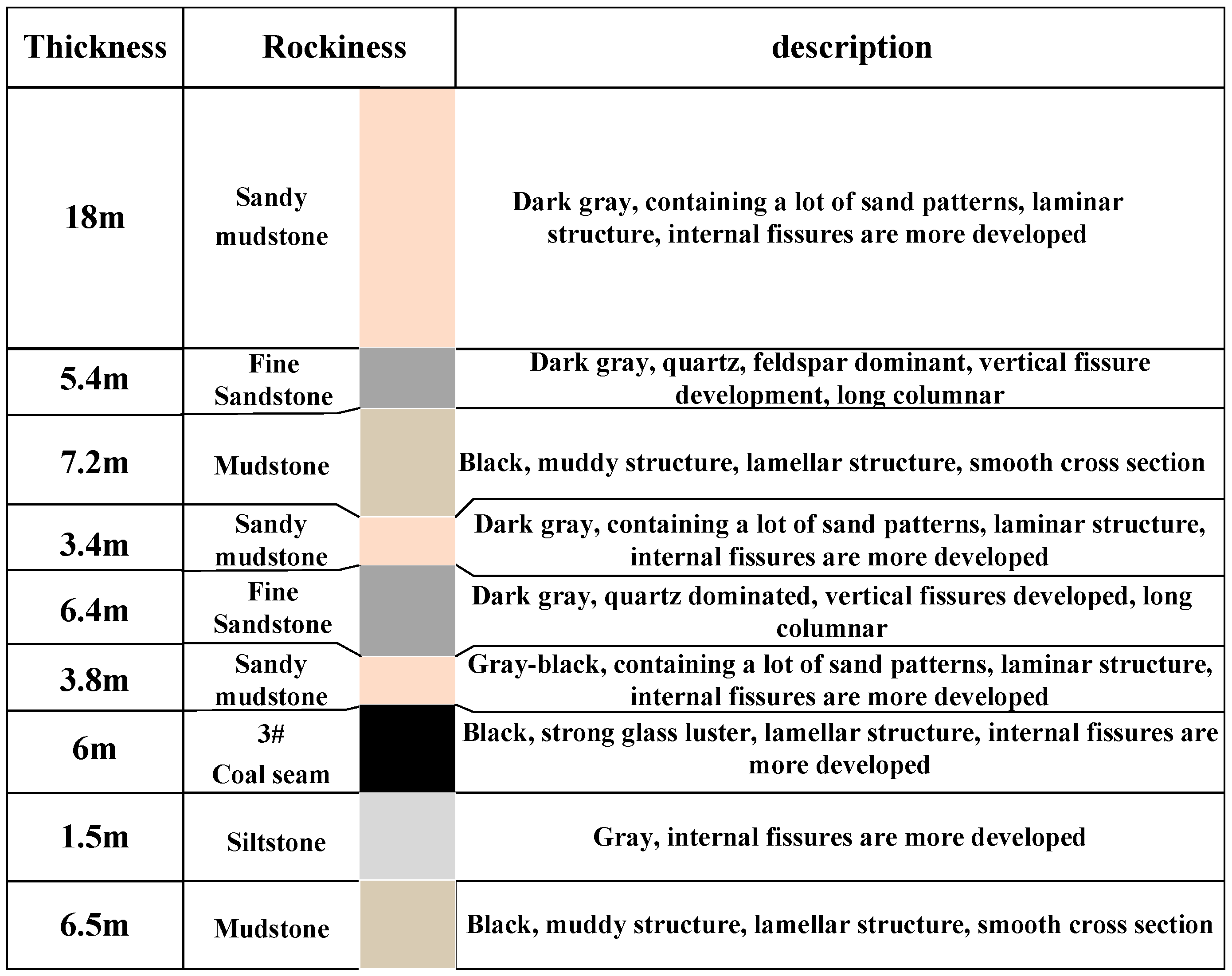
The Tangan coal mine of the Jincheng Lanhua Group, with an average burial depth of about 450 m, carries out a gob-side entry retaining test in the 3# coal of the 3 panel. The effect of the previous gob-side entry retaining in the 3303 working face was not satisfactory, and this engineering test was carried out in 3310 working face in the same panel with similar distribution characteristics after improving the technical scheme. As shown in Figure 1 and Figure 2, the 3310 gob-side entry retaining is reused as the 3312 working face’s belt transportation roadway, with an average coal seam thickness of 6 m and a mining ratio of 1:1, and the roadway is excavated along the floor.

2.2. The Original Gob-Side Entry Retaining Support Situation

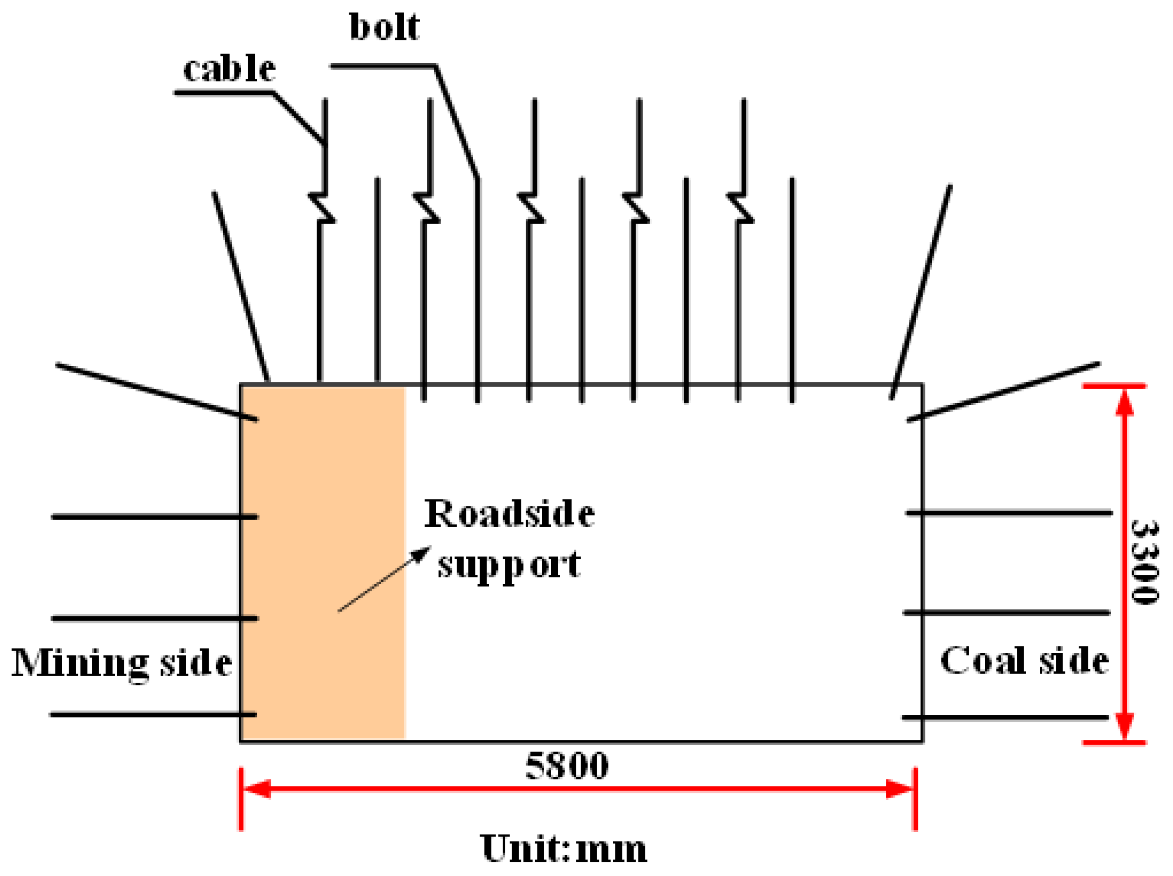
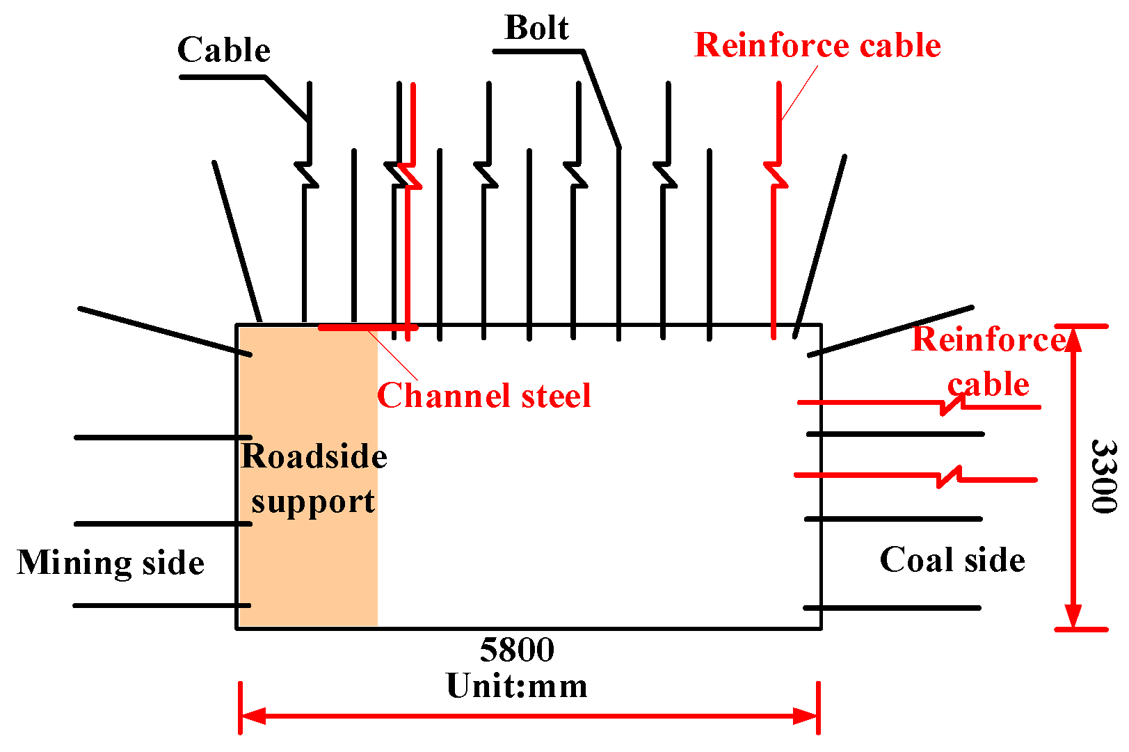
The height of the original roadway of the 3303 working face is 3.3 m, and the width is 5.8 m. The width after the installation of a flexible formwork concrete roadside support gob-side entry retaining is 4.4 m. The roof is supported by bolts, cables, and nets; the top cable adopts a “three two” arrangement, and two sides are only supported by bolts, as shown in Figure 3.

2.3. Deformation Characteristics of Gob-Side Entry Retaining

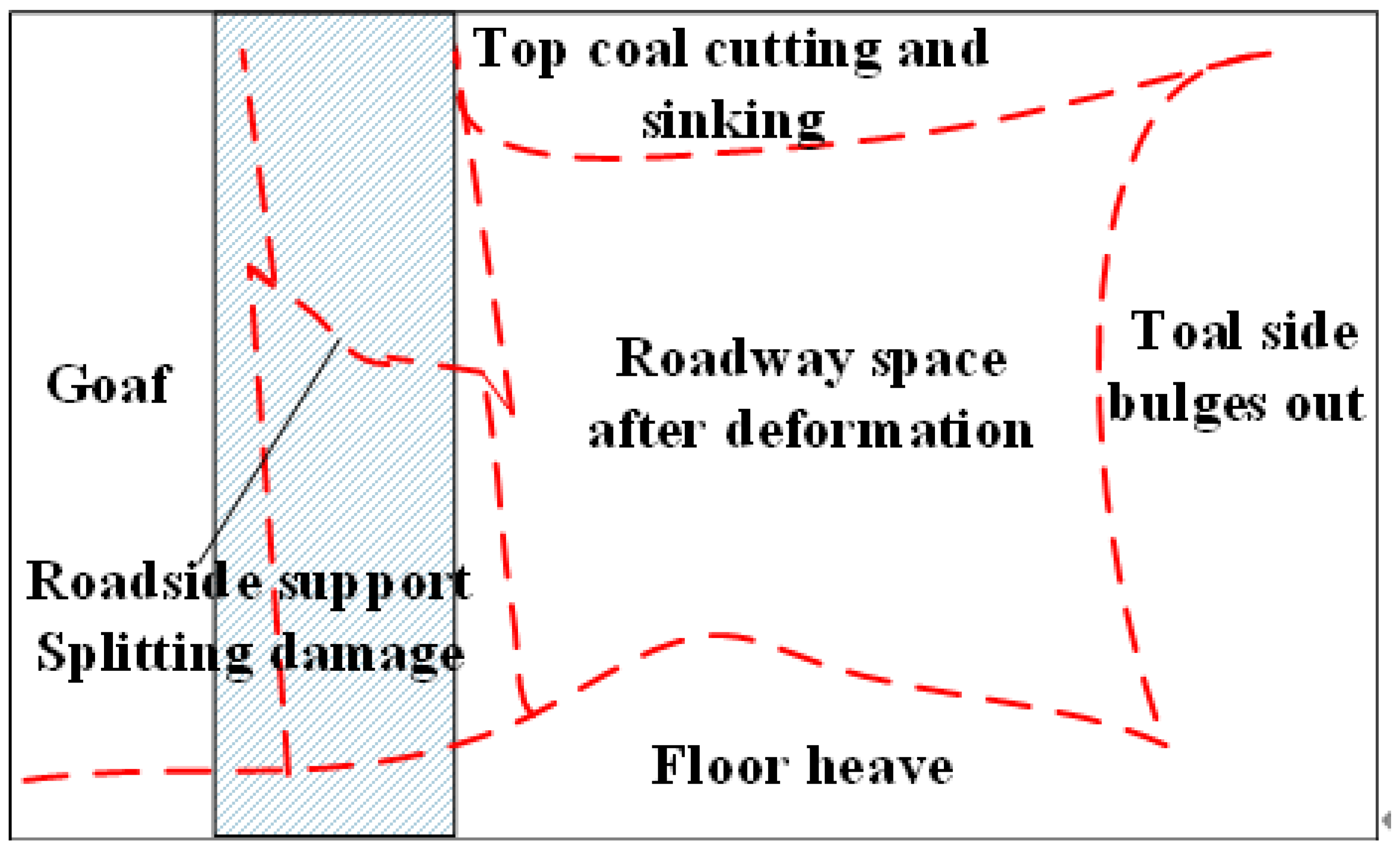
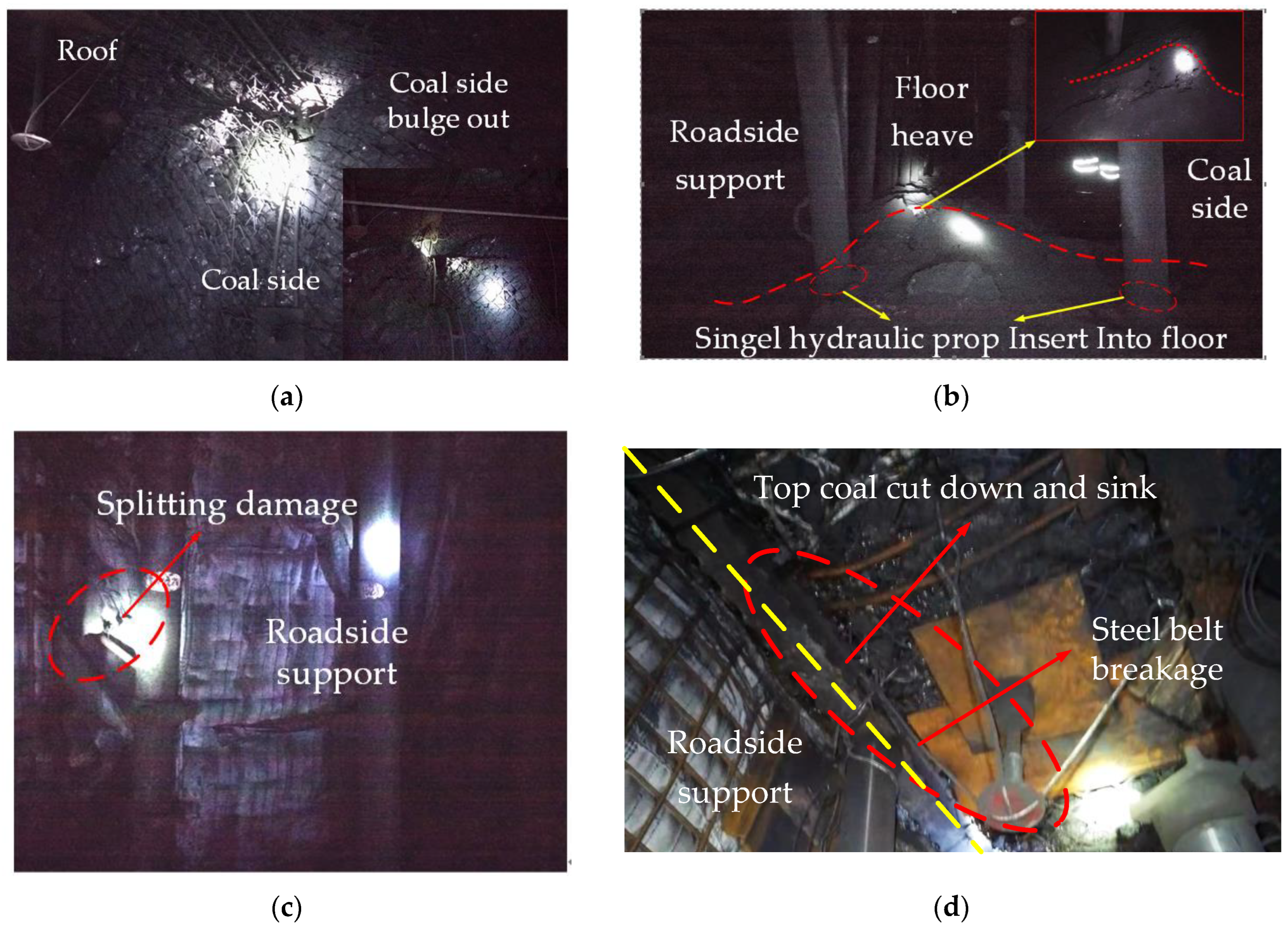
After the observation and analysis of the 3303 gob-side entry retaining, it can be seen that it has typical asymmetric overall deformation damage characteristics as a result of the top coal sinking along the inner side of the roadside support, as well as from the concrete roadside support structure skewing and even showing splitting damage as a whole, floor heave, the coal-side bolt support structure basically losing support ability and bulging out of the coal side as a whole. As shown in Figure 4 and Figure 5, the deformation shows obvious integrality, and the top, bottom, and coal sides affect each other, so the deformation control of gob-side entry retaining should consider the roadway as an organic whole.

3. Leading Factors of Asymmetric Deformation Damage in Gob-Side Entry Retaining

3.1. Water Disintegration of Roof Mudstone and Deflection under Horizontal Stress

The physical and mechanical properties of the 3 coal mine and the top and bottom rock samples were tested. The mineral composition of the top and bottom rock is mainly quartz, mica, illite, kaolinite, and perlite. The mineral content of the mudstone of the floor was calculated as follows: 19% quartz, 8% mica, 39% illite, and 4% kaolinite. Kaolinite, illite, and other minerals are weakly bonded by themselves and are prone to dilatancy deformation and strength deterioration upon encountering water. After analyzing the softening and disintegration characteristics of the rocks, it was found that all the mudstones show water disintegration characteristics, except for the sandstone.
In the 3303 working face, which has a completed gob-side entry retaining but has not been reused, there is a lot of water that has not been pumped and drained for a long time. The mudstone of the floor has therefore been soaked for a long time, which further aggravates the plastic damage and damage depth of the floor due to water disintegration. As the gangue in the goaf plays a bearing role, the vertical stress of the two sides also gradually stabilizes. Because the single hydraulic pillar in the gob-side entry retaining was removed, the upper part of the floor is basically in the unsupported state. Therefore, the disintegration damage results in the overall strength of the floor being obviously weakened, and the deep floor produces an upward thrust on the shallow floor under deep, high-level stress, resulting in shallow floor deflection damage occurring in the roadway.

3.2. Splitting Damage of Concrete Roadside Support under Asymmetric Load

The interior of the original roadside support of Tangan coal mine is basically a plain concrete structure. Although the flexible formwork is water permeable but is impermeable to cement slurry, the early strength of the concrete is improved. However, the interior of the wall is still a plain concrete structure. The concrete material itself is non-homogeneous and brittle, the overall resistance to tensile and shear damage is weak, the ductility is poor, and the residual strength of the roadside support is low once the integrity of the roadside support is destroyed.
Measurements show that the sinking of the top coal and roof above the roadside support in gob-side entry retaining will produce “asymmetric” load on the roadside support. The integrity and load-bearing capacity of the roadside support is reduced by the damage of the wall structure, and the expansion deformation of the top coal cutting and sinking also generates a load on the roadside support towards the goaf. At the same time, the deflection deformation of the floor causes the roadside support to slip into the gob-side entry retaining space.
Therefore, the strength and deformation resistance of the roadside support itself is weak, and the complex load action is the root cause of skewing, splitting damage, and the loss of bearing capacity after the wall damage aggravates the deformation.

3.3. Insufficient Support Strength of the Coal Side Leads to Damage and Expansion

After gob-side entry retaining, the maximum amount of coal side deformation is 0.7~1 m. With the increase in the length of gob-side entry retaining, the plastic zone continues to expand, and the bolt support fails frequently. The existing bolt support strength can no longer effectively control the deformation. The roadside support being unable to carry load effectively further causes the coal side to bear the superimposed effect of the higher mining stress field and the raw rock stress field. The lower strength of the shallow part of the coal side leads to the continuous expansion of the plastic zone of the coal side to the deep floor, which intensifies the expansion and extrusion deformation.

3.4. Strong Dynamic Pressure of the Roof and the Influence of Pressure Relief

The mining pressure characteristics of the gob-side entry retaining are different from the general dynamic pressure roadway. The collapse zone and fissure zone or even the high roof of the bending and sinking zone will produce continuous, strong, dynamic, and static pressure effects on the gob-side entry retaining in the goaf, which will cause continuous deformation of the gob-side entry retaining until the goaf is compacted and stabilized.
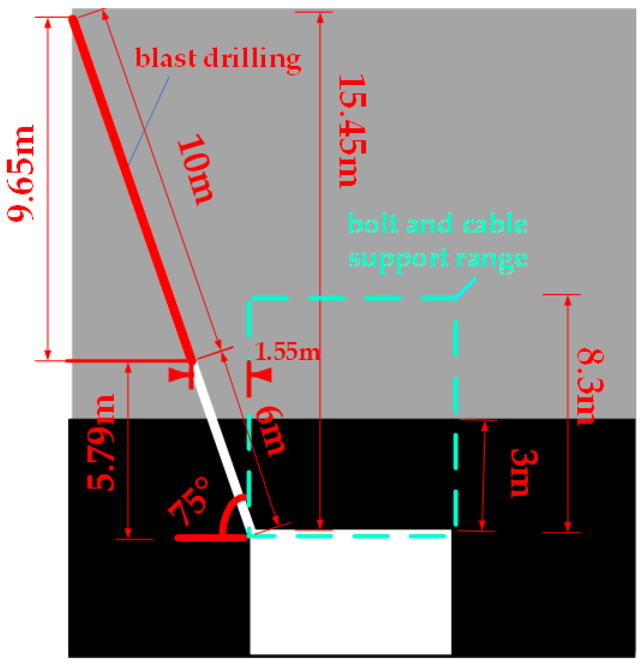
As shown in Figure 6, the length of the top-cutting pressure relief drilling hole is 16 m. The blast hole is set up at the shoulder of the roadway, with a 50 mm diameter, a 600 mm spacing along the roadway, a 6 m sealing length, and a 10 m blast length. After calculation, the actual blasting roof’s vertical height is 9.65 m, and the closest distance from the blasting section to the roof anchorage range is 1.55 m. According to the calculation of the mining height of 6 m and a coefficient of fragmentation and expansion of 1.2, the ideal blasting height should be more than 30 m, so as to make the rock layer within the blasting range collapse as soon as possible and fill the goaf effectively in time, in addition to playing a supporting and buffering role for the overlying roof. However, the previous pressure relief only considered the low basic rock layer, and its height was insufficient.
Pre-cracked blasting dealt with the low, hard, and difficult to collapse rock layer to reduce, to a certain extent, reduce the impact of the roof’s collapse and the lateral overhanging roof on the gob-side entry retaining. However, it is still difficult to fully fill the goaf in time after the low roof collapses. The sinking and fracturing of the high roof in the goaf will still produce large dynamic pressure and lateral pressure on the gob-side entry retaining, causing deformation.
In addition, the blasting pressure relief does not entirely avoid the support anchorage area. Indeed, the blasting impact area and the cable support anchorage area overlap each other in the vertical direction, and the minimum horizontal distance is only 1.55 m. Therefore, the blasting vibration will seriously affect the support bearing structure and the integrity of the roof near the gob-side entry retaining on the goaf side.

4. New Mutual Synergistic Deformation Control Technology of Support and Pressure Relief

Based on the analysis of the causes of the deformation and damage of the gob-side entry retaining, the deformation of the surrounding rocks can be controlled in a targeted manner by relieving pressure to weaken the dynamic and static loads in the gob-side entry retaining, reducing the width of the plastic zone of the coal side by strengthening the support, reasonably reducing the width of the roadside support on the premise of optimizing the structure to ensure its bearing capacity, and increasing the strength and deformation resistance. Therefore, a high-strength, reinforced thin concrete roadside support, a steel-cable belt reinforcement support for the roof of inner the roadway, a top-cutting control reinforcement support of the gob-side entry retaining, a reinforcement support of the “pillar hydraulic support + π-type beam”, and hydraulic fracture pressure relief system for the initial mining and for the horizontal long drilling “fracture-jet” pressure relief before mining were designed. The deformation control scheme is demonstrated and industrial tests were conducted to verify the effect of these supports on rock control.

4.1. Roadside and Roadway-in Support

4.1.1. High-Strength, High-Stiffness, High-Ductility Roadside Support Structure

The new reinforced thin concrete roadside structure with high strength, high stiffness, and timely support of the roof is adopted. This structure overcomes the shortcomings of traditional roadside support such as high brittleness and poor overall strength and deformation resistance and forms an internal reinforcement and external double-layer constraint structure to increase the ability of the roadside support to withstand complex loads.
As shown in Figure 7, the design thickness of the roadside support is 1.2 m, the size is 4.6 m × 3.3 m, and the concrete proportioning grade is C40. In order to increase the roadside ability to resist floor heaving and attain full load-bearing capacity, when the roadway is under strong pressure, the overall inclination of the roadside support to the roadway space is 2~3°.

4.1.2. Roadway-in Reinforcement Support

The phenomenon of the top coal sinking along the inner side of the roadside support and the bulge out with the coal side is a typical deformation characteristic. Based on the deformation integrity, it is necessary to strengthen the support to improve the coal side support’s strength, control the rapid expansion of the coal side’s plastic zone, and prevent the top coal from sinking.
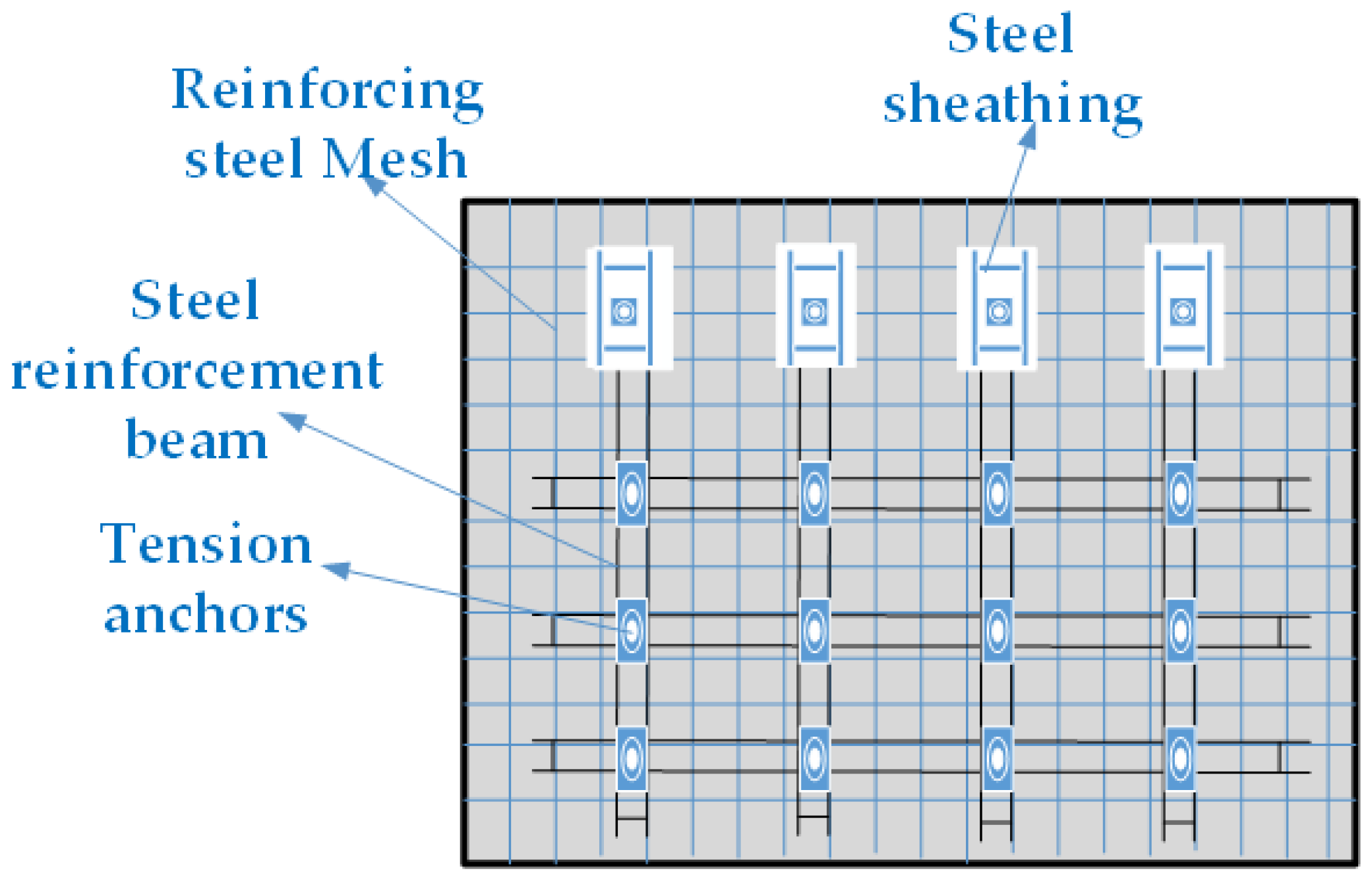
The 3310 gob-side entry retaining reinforcement support scheme is shown in Figure 8. The cable material adopts φ22 mm 1 × 19 strands of high-strength, low-relaxation prestressing steel; the top cable length is 8.3 m; and the coal side cable length is 4.3 m. The bolt adopts φ20BHRB400 high-strength, left-handed rebar, and the steel belt is BHW-280-3.00. The mesh is a 50 × 50 mm diamond-shaped metal mesh woven with 8# lead wire, and the steel beams are welded with φ14 mm steel bars.

4.2. Setup Entry Hydraulic Fracturing Pressure Relief

In the initial mining stage of the working face, due to the end-face support effect of the solid coal behind the setup entry, the overlying roof does not fall after mining, which can easily form a large area of initial pressure and gas exceeding its limits. In the process of gob-side entry retaining, if the strong initial pressure formed by the roof in the goaf does not collapse in time, it will not only threaten the safety of the working face, but the strong impact load will also affect the stability of the rock surrounding the gob-side entry retaining and the roadside support.
Therefore, the proposed design of the initial mining pressure relief scheme of the setup entry hydraulic fracturing, on the one hand, promotes the timely collapse of the roof, ensuring that the gob-side entry retaining is protected from severe impact load. On the other hand, it optimizes the stress environment and, at the same time, promotes the release of the top-coal caving mining face, as shown in Figure 9.

4.3. Advanced Horizontal Long Borehole “Fracturing-Jet” Pressure Relief Technology

4.3.1. Horizontal Long Borehole Regional Hydraulic Fracturing Process

Compared with traditional blasting, advanced horizontal long borehole “fracturing-jet” technology provides early pressure relief along the gob-side entry retaining, especially in the high gas mine, which not only has significant advantages in process and safety, but also has a large fracturing influence range and high efficiency, and can realize “vertical layering and horizontal segmentation” fracturing.
Horizontal long borehole regional fracturing is to set up drill horizontal holes in the target rock layer using a high-displacement, high-pressure pump and a high-power directional drilling rig to achieve full fracturing and water injection to weaken the target layer. This approach promotes the orderly collapse of the roof, the timely filling of the goaf, and optimizes the stress environment in the area of the gob-side entry retaining, as shown in Figure 10.

4.3.2. Fracturing Layer and Parameter Design

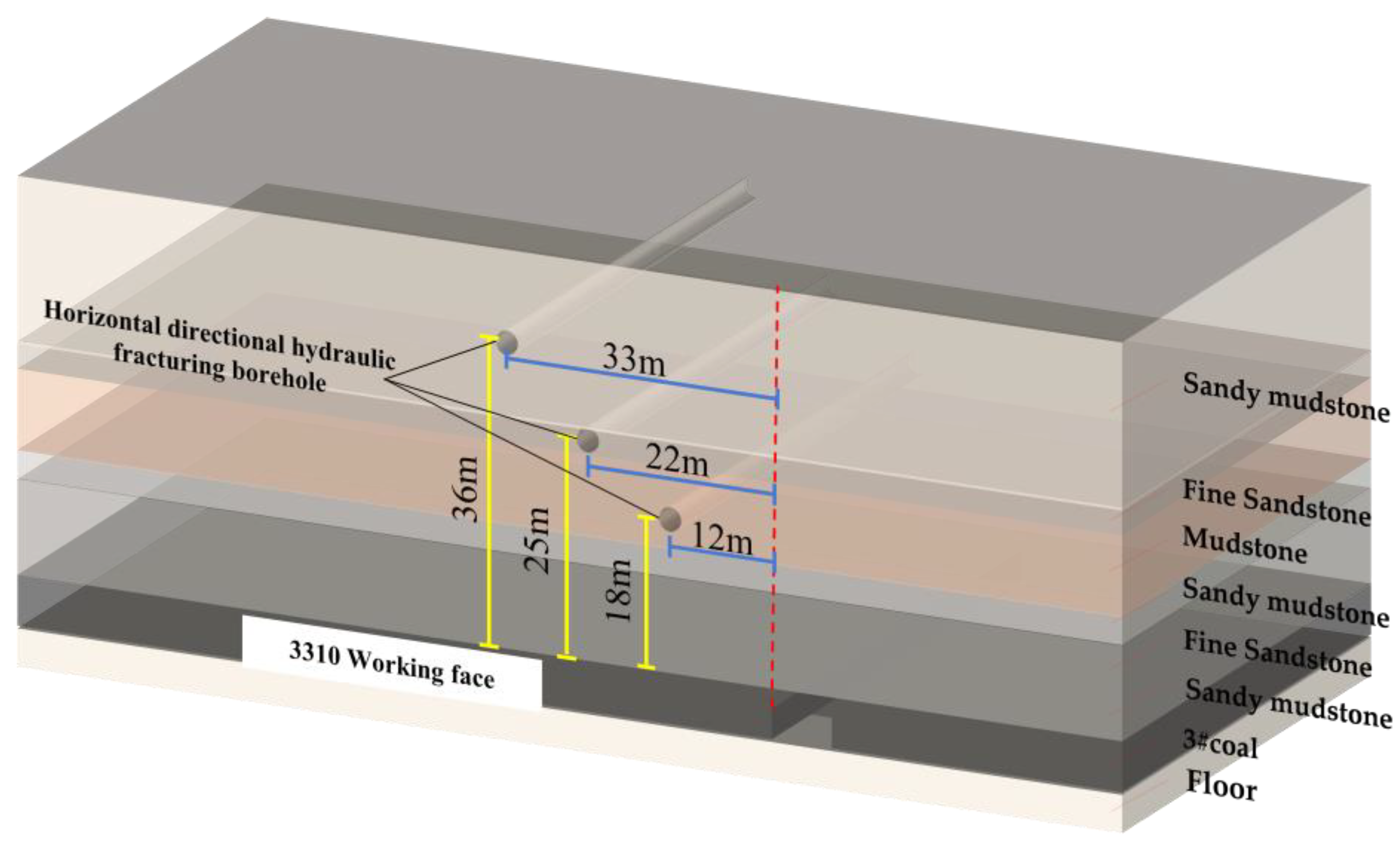
Three drilling sites are horizontally arranged along the working face alignment, and each drilling site has a horizontal design length of 500~600 m for segmented backward fracturing. As the advancement of the fracturing device requires high integrity of the rock borehole, when it encounters an unstable layer rock and poor rock integrity, fracturing cannot be effectively realized, and a high-pressure water jet is used as a supplement to create the “fracturing-jet” horizontal long borehole for pressure relief. The fractured holes can also be used as extraction holes for the extraction of gas from the goaf, improving the efficiency of gas extraction from the goaf while weakening and cutting hard rock layers.
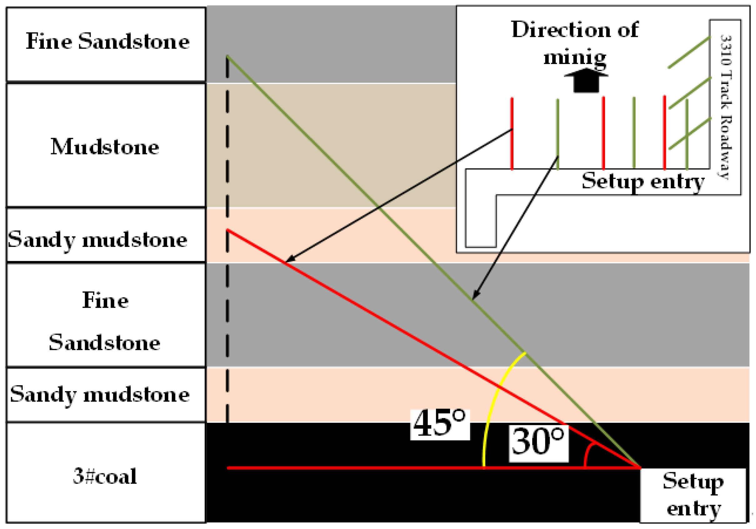
Considering the effect of fracturing on the space of the gob-side entry retaining, the layer design is shown in Figure 11. As the sandstone layer has not been blasted to cut the roof, but the top-cutting borehole has been constructed in advance and the intensive borehole has weakened the low fine sandstone layer to some extent, there is no hydraulic fracturing in the low sandstone layer. Instead, the horizontal fracture boreholes are designed in the thick mudstone layers with good integrity, the high sandstone layers with greater hardness, and the sandy mudstone layers with greater thickness.
Hydraulic fracturing is used to overcome the ground stress around the borehole and the tensile strength of the rock formation using high-pressure water to produce tensile fractures in the hole wall. High-pressure water is injected with a certain pressure to make further expand the fractures after they are initially produced. High-pressure water injected into the rock formation in large quantities during fracture expansion results in natural primary fractures and hydraulic fractures which can both weaken the rock formation. Based on the elastic theory, without considering the primary fracture, the initial fracturing water pressure used in hydraulic fracturing is P i , T is the rock tensile strength, σ 1 and σ 2 are the maximum and minimum principal stresses in the borehole plane, respectively, and the fracture extension pressure is P s . The units of all variables are MPa. P i is calculated as follows:
P i = 3 σ 2 σ 1 + T
The measured horizontal stress in the Tangan coal mine is slightly higher than its vertical stress, specifically 1.2 times higher. The vertical and horizontal stress are taken as the minimum and maximum principal stresses for calculation: 11 MPa is taken as the vertical stress and 13.2 MPa as the horizontal stress. According to the tests of the surrounding rock’s physical and mechanical parameters, the maximum compressive strength of the fine sandstone of the roof is 60~70 MP. The maximum pressure of the fracturing pump can reach more than 40 MPa, which is calculated to be able to achieve full fracturing of all fractured layers.

5. Dynamic Monitoring and Analysis of Gob-Side Entry Retaining Engineering Effects

5.1. Mining Pressure Monitoring Program

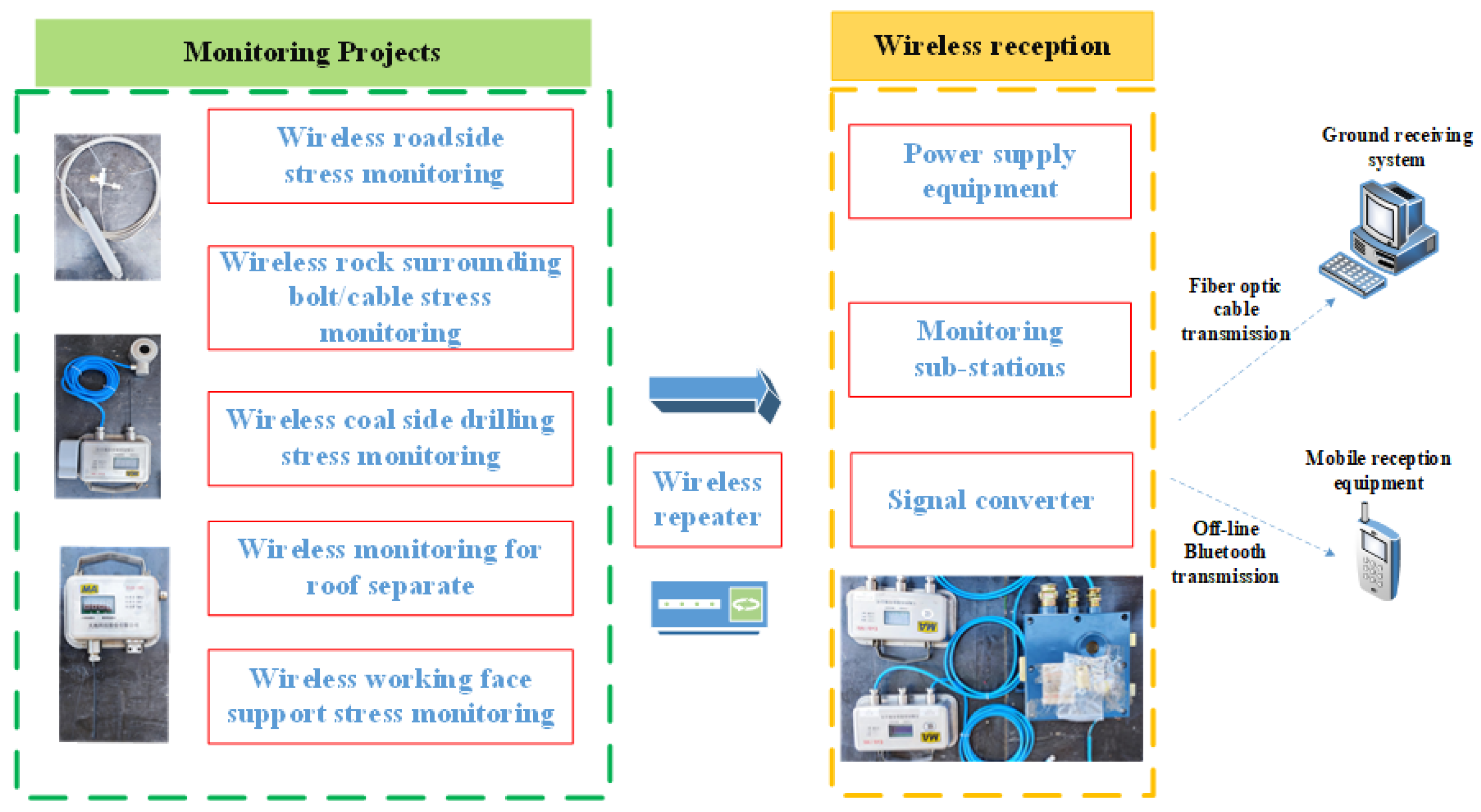
As shown in Figure 12, in order to realize the dynamic real-time monitoring of stress and deformation in the process of gob-side entry retaining and evaluate the effect of the surrounding rock deformation control, the wireless mining pressure monitoring system is arranged and dynamic monitoring of the roadway surrounding rock deformation is carried out. Wireless stress monitoring mainly includes working face bracket stress monitoring, coal side drilling stress monitoring, roadside support (wall) stress monitoring, and surrounding rock bolt/cable stress monitoring. Surrounding rock deformation monitoring mainly includes recording the amount of displacement in the surrounding rock displacement and roof monitoring.

5.2. The Effect of Pressure Relief

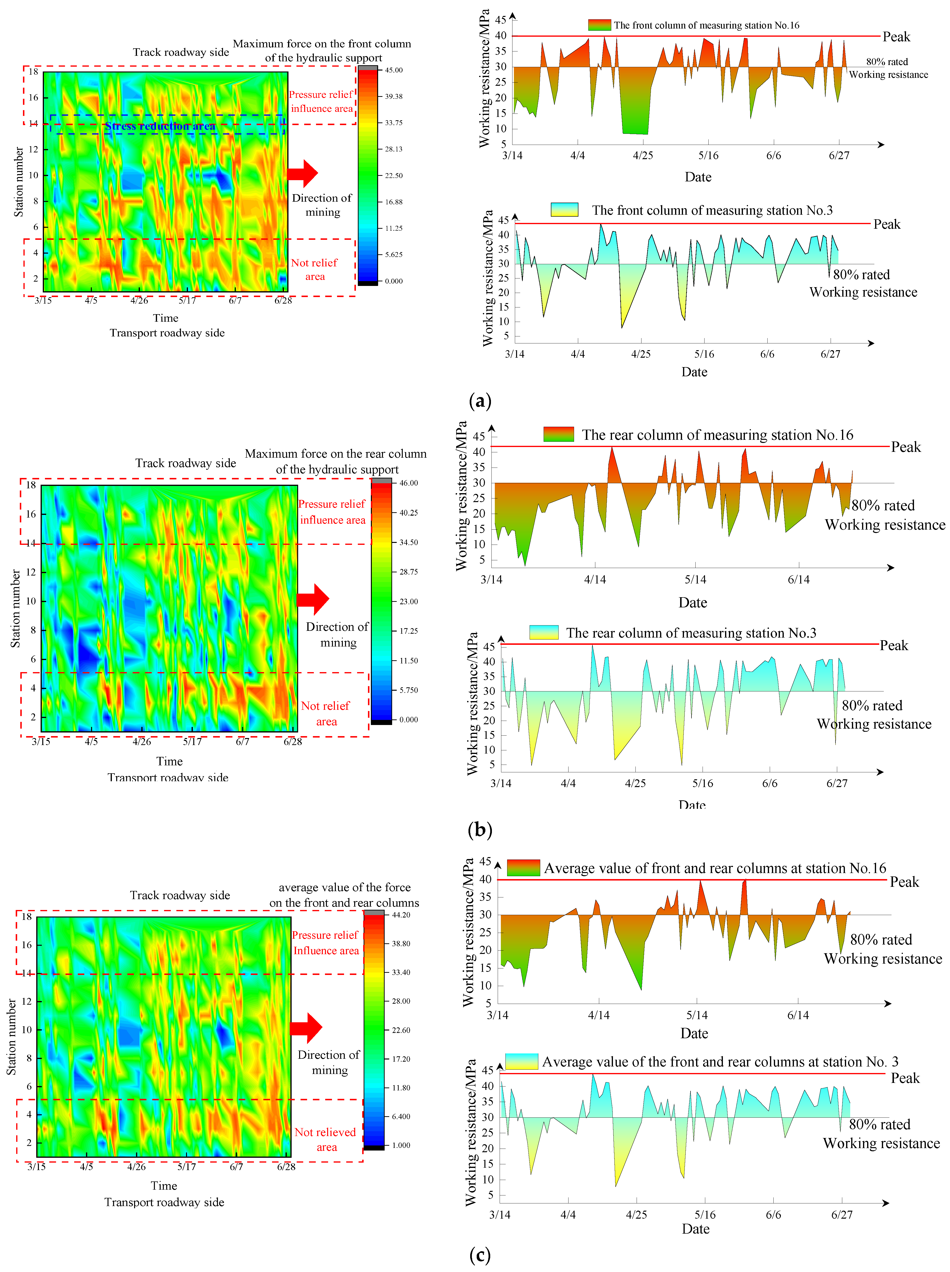
The hydraulic bracket of the Tangan coal mine working face is ZF7200/17/33, the bracket working resistance is 7200 KN, the bracket’s rated initial bracing force (6184 KN) is 31.5 MPa, and the rated working resistance (7200 KN) is 36.7 MPa. After the horizontal long borehole fracturing is carried out in the roof, the real-time bracket stress of the working face is monitored. A total of 156 stents were arranged on the working face, and a total of 18 measuring stations were arranged. According to the parameters of the maximum influence range of horizontal long borehole fracturing obtained from a large number of engineering tests, the influence zone of horizontal long borehole fracturing is delineated as shown in Figure 13.
As shown in Figure 13a–c, the area without pressure relief on the side of the transportation roadway experiences pressure for a long duration during workface mining and presents a large area of continuously high stress on the stress contour, which indicates that the overlying roof cannot fracture and collapse in time, causing difficulties in advancing the workface. In the pressure relief influence area on the side of the track roadway, the degree of pressure and the duration of pressure from the bracket are obviously reduced, and a small range of high-stress areas only appear intermittently, indicating that the overlying roof does not have a large area of overhang in this range and that the roof behind the working face is broken in time during the mining process. In the vicinity of the No. 14 measuring station in the stress contour (a) of the front column of the bracket, the stress reduction zone, which is obviously lower than the bracket on both sides, appears during the workface advancement, indicating that the overall strength of the lateral roof of the track roadside is weakened after the fracture and that it can be broken in time without forming a longer overhanging roof, which controls the high stress transfer from the overhanging roof to the gob-side entry retaining space and effectively improves the stress environment.
From the overall comparative analysis of Figure 13a–c, it can be seen that after the early cracking and pressure relief, the stress on the bracket in the pressure relief area on the track roadway side is, on the whole, significantly reduced compared with that on the transportation roadside. When the working resistance of the bracket is higher than 80% of the rated working resistance, the bracket is considered to be in a high stress state. Therefore, the stress curves of the No. 16 measuring station in the pressure relief area and No. 3 measuring station in the unrelieved area can be analyzed separately, and it can be seen that the peak stress and high stress duration of measuring station No. 16 in the relief area are significantly smaller than those of bracket No. 3 in the unrelieved area. In addition, the stress state of bracket in the relief area is significantly better than that of the unrelieved side.
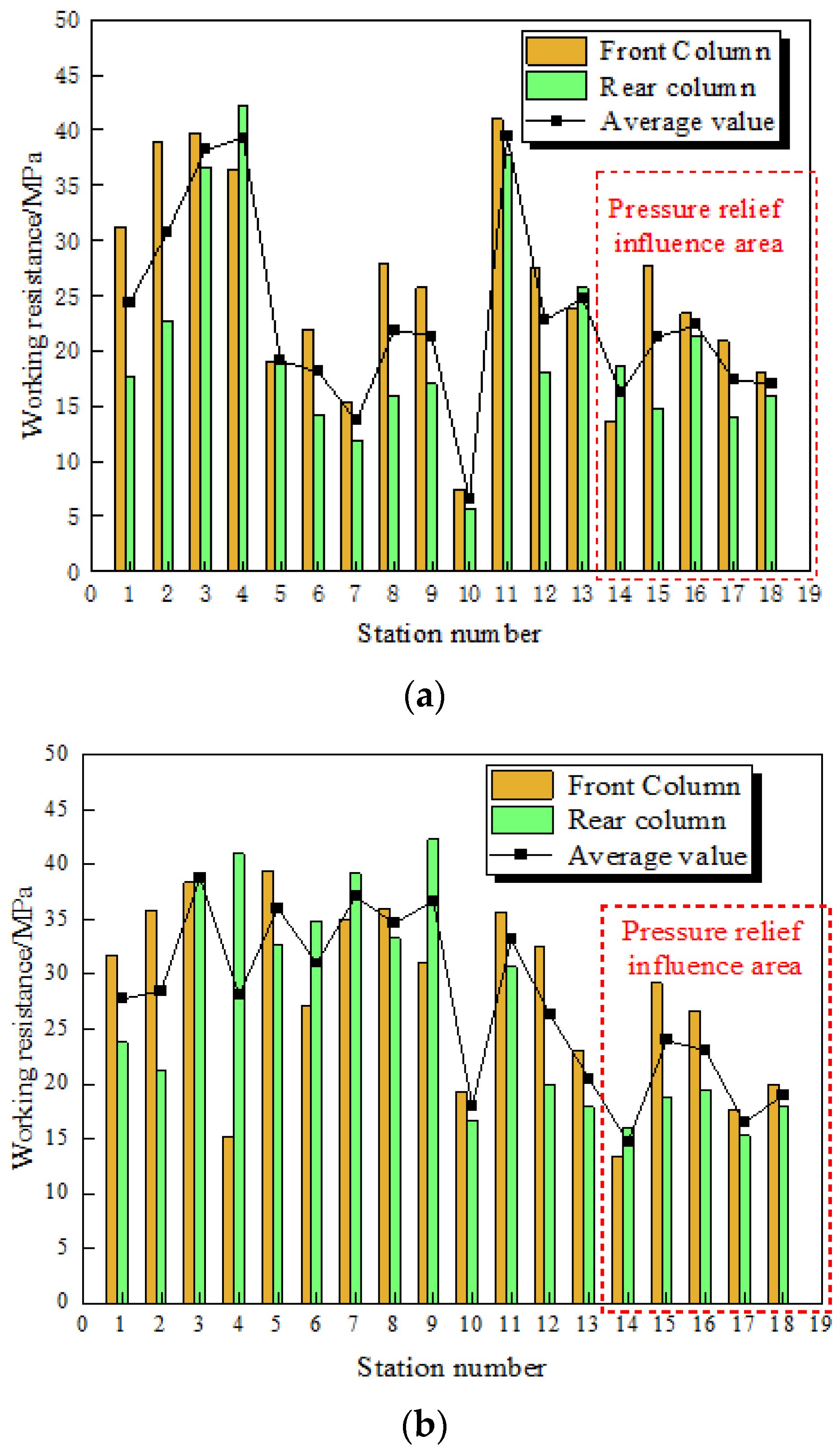
As shown in Figure 14, the analysis of bracket stress along the working face inclination direction shows that the bracket of measuring stations No. 17 and No. 18 near the pressure relief area of the track roadway side is significantly lower than the bracket force of measuring stations No. 1 and No. 2 near the transportation roadway side. After several rounds of statistical data analysis, the average stress value on the bracket of stations No. 17 and No. 18 is about 35% lower than the average value of the force on the bracket of stations No. 1 and No. 2.
A comprehensive analysis of the stress contour of the bracket and the stress state of the bracket along the roadway direction and along the working face inclination direction shows that the application of the horizontal long borehole fracturing technology significantly improves the surrounding rock stress environment of the working face near the side of gob-side entry retaining. The stress state of the bracket not only intuitively indicates the stress state, but the timely collapse of the roof can also reduce the concentration of the front abutment pressure and weaken its influence. Similarly, the timely fracturing and collapse of the roof at the back of the working face also reduces the lateral roof overhang of the gob-side entry retaining, so that the lateral roof can collapse in time to fill the goaf.

5.3. Deformation of the Surrounding Rock in Gob-Side Entry Retaining

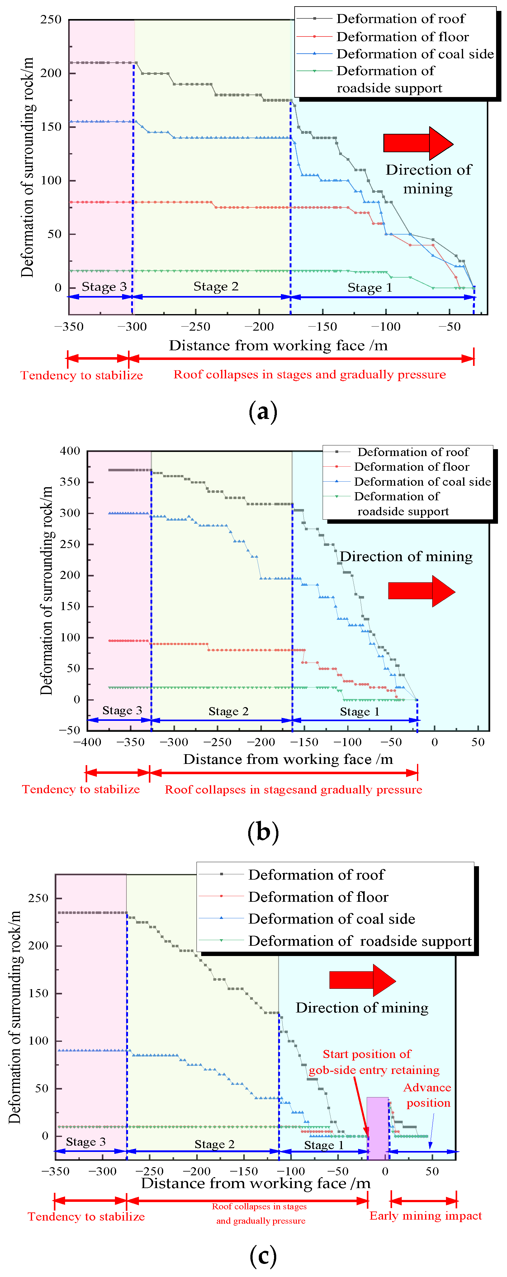
In the 12#, 20#, 45# roadside support positions, surrounding rock displacement measurement points were arranged for continuous observation. By comparing the data from these points, it is found that the surrounding rock deformation presents obvious spatial and temporal change characteristics and shows a typical phase. From Figure 15a–c, it can be seen that there are three basic stages from the beginning of gob-side entry retaining to the stabilization of the rock deformation: the first stage is the rapid deformation stage at the beginning, the second stage shows a decrease in deformation acceleration at the middle, and the third stage shows a stabilization creep stage at the end. The deformation of the surrounding rocks mainly occurs in the first and second stages, accounting for more than 90% of the total deformation.
As shown in Figure 15c, within 50 m in advance of the working face, due to the influence of the front abutment pressure, the surrounding rock of the roadway also produces a certain degree of deformation. However, as a result of the pressure relief and reinforcement support of the coal side 500 m in advance, the maximum deformation within 50 m of the roadway is less than 50 mm, and front abutment pressure and the total deformation of surrounding rock is not obvious.
The monitoring curve of the deformation occurring in the surrounding rock of roadway in Figure 15a–c shows that the deformation of the 3310 gob-side entry retaining basically tends to be stable and slow creep after passing 300 m from the lagging working face. The deformation of the roof and the coal side are the main factors here, and the maximum sinkage of the roof is controlled within 370 mm in the crushed area of the surrounding rock; other areas are controlled between 200 mm and 250 mm. The deformation of the floor is effectively controlled by pressure relief technology and strengthening support. The maximum amount of floor heave is 100 mm, which means there is basically no need to repair it before reuse, and the total amount of deformation in the roof and floor is less than 14%. The maximum deformation is 300 mm in the coal side in the crushed area of the surrounding rock, and the deformation in other areas is basically controlled between 100 and 170 mm. The deformation of the roadside support in each measurement point is less than 100 mm, the surface integrity is good, and the total displacement of the two sides is less than 8%.

5.4. Stress Characteristics of Coal Side

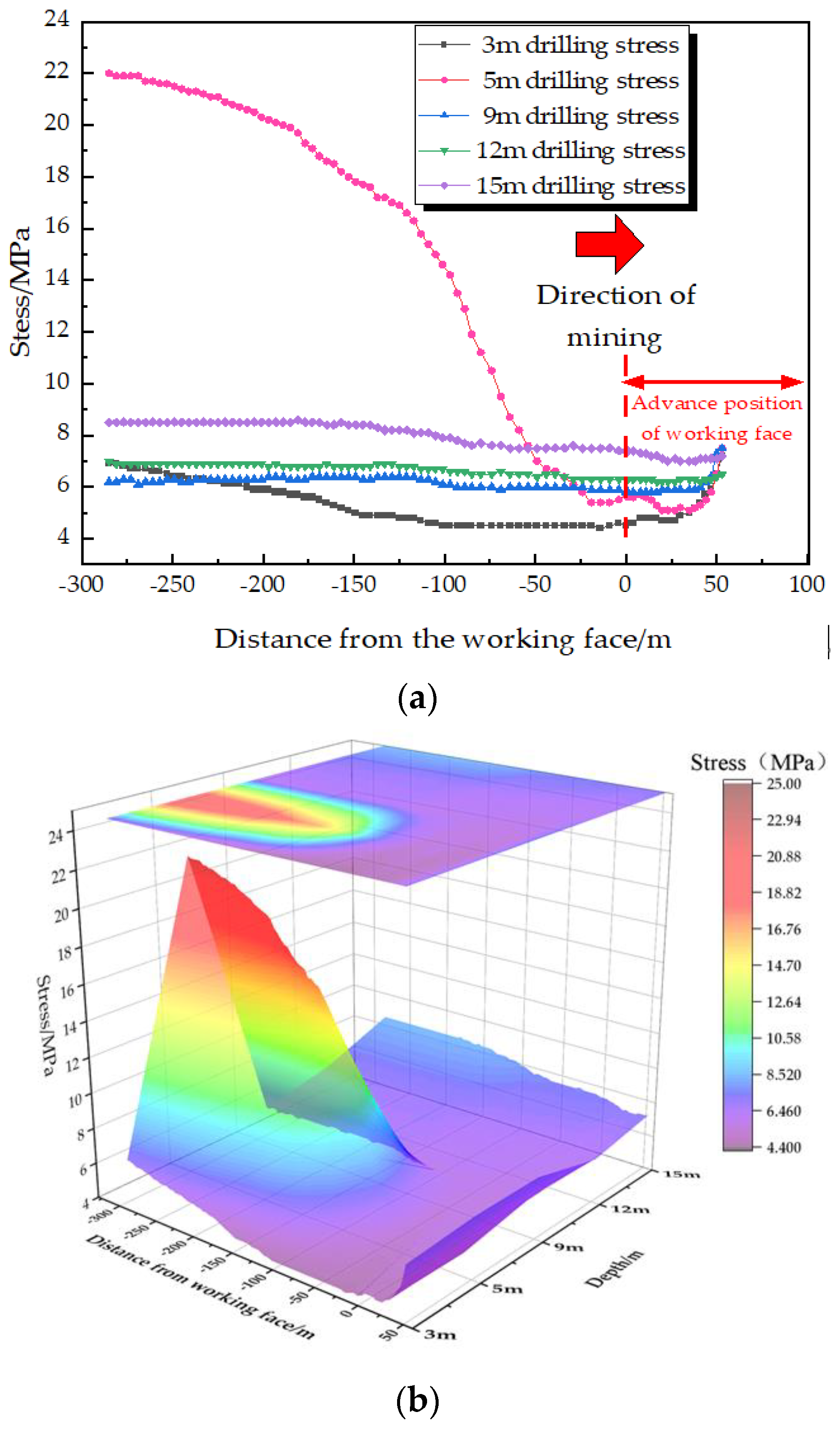
The purpose of drilling stress monitoring is to monitor the relative stress inside the coal, which can dynamically reflect the changes in the stress and plastic zones at different depths in the coal side. In order to monitor the stress characteristics of the coal side at different depths during the process of gob-side entry retaining, stress measurement stations were arranged at the 3310 working face starting at 60 m ahead. Drillholes perpendicular to the coal side at different depths are designed. The specific arrangement plan is shown in Figure 16, with five boreholes in each group. The drilling position is in the middle of the coal side, and the installation depths are 3 m, 5 m, 8 m, 12 m, and 15 m, in order. The diameter of the boreholes is 42 mm, and the distance between adjacent boreholes is 2 m. Through the wireless data receiving equipment, the change curve of the drill hole stress with the advancement of the working face was collected dynamically and continuously, as shown in Figure 17. The positive value of the horizontal coordinate represents the front of the working face, and the negative value represents the lagging of the working face.
From Figure 17, the following can be observed: ① The stress in boreholes with depths of 8 m, 12 m, and 15 m shows a slowly increasing trend after the initial pressure, which indicates that the coal in this range is in the elastic stage. In addition, the change in the stress state of the coal in this range during gob-side entry retaining stage is not obvious, and plastic damage did not occur. ② When the boreholes with depths of 3 m, 5 m, 8 m, 12 m, and 15 m are within the influence range of the front abutment pressure, the stress fluctuates withing a range of less than 2 MP, which indicates that the front abutment pressure on the coal side has been effectively controlled under the action of pressure relief. ③ In the range of 0~50 m in front of the working face, the stress of boreholes of different depths all showed different degrees of decrease in the initial stage. The decrease in stress from the shallow part of the coal side to the deep part gradually increases, and the stress decrease in the 3 m deep borehole is more than 30%, indicating that the integrity and bearing capacity of the coal side of the roadway gradually increases from the shallow part to the deep part. ④ After the initial stress equilibrium is reached in the borehole, the stress in the borehole at 3 m depth showed a small decrease again, indicating that further plastic damage occurred in the shallow surrounding rock of the roadway. The bearing capacity is more stable and increases by a certain extent after entering about 100 m into the gob-side entry retaining, which indicates that the “bolt (cable)-net-steel belt” joint reinforcement support scheme has effectively improved the post-peak residual load-bearing capacity of the shallow part of the coal side. Moreover, the reinforced thin concrete wall of the roadside support and the coal side also achieves effective joint bearing. ⑤ The stress in the boreholes at 3 m and 5 m depths both show a certain stress drop after entering the gob-side entry retaining, indicating that the overlying roof is fractured once between 3 m and 5 m in the coal side in the lateral direction. ⑥ The stress in the borehole at 5 m depth continues to increase after 25 m into the lagging working face and does not show a decreasing trend. It stabilizes around 280 m into lagging working face, indicating that the coal does not enter the plastic stage before the stress peak in a certain range within 5 m of the coal side. No post-peak plastic damage occurs in the process of stress increasing, but it does in the elastic zone.

5.5. Strength and Force of Roadside Support

5.5.1. Roadside Support Strength Test

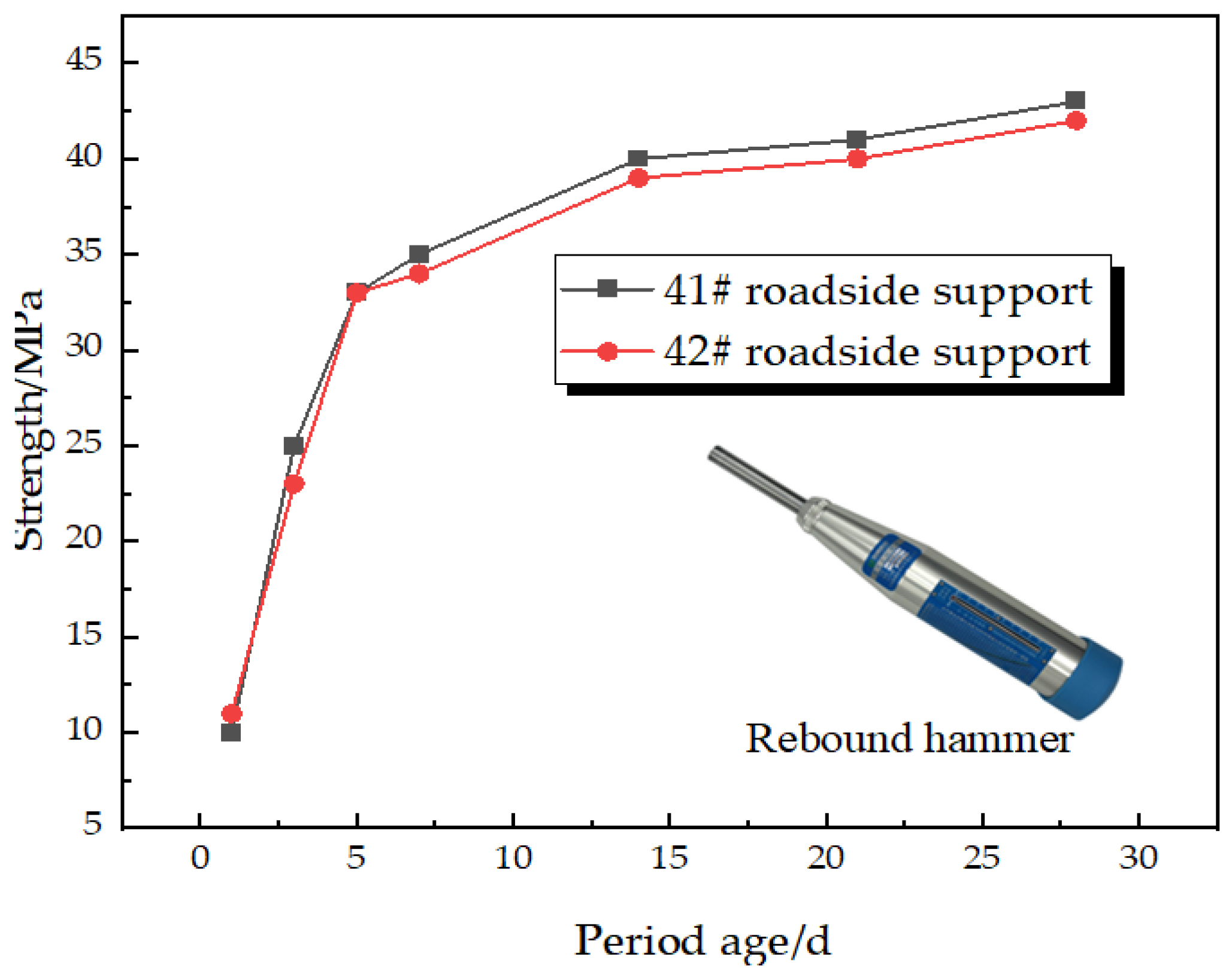
In order to accurately test the strength of the concrete roadside supports, the strength was continuously monitored by means of a rebound hammer and a compressive strength test of a concrete specimen in the labratory, respectively. The data obtained from the rebound hammer test in the 41# and 42# lane side supports are shown in Figure 18, and after strength conversion, they both meet the design requirement of C40 concrete strength.
In order to test the strength of concrete materials more accurately under the actual temperature and humidity conditions in the underground, concrete specimens of 100 mm × 100 mm were prepared in molds and maintained periodically, and their strength was tested with a pressure testing machine with a strength conversion factor of 0.95. A total of seven groups of test specimens were made and maintained for 1 d, 3 d, 5 d, 7 d, 14 d, and 28 d; three standard pieces were made for each period age, and a total of 15 concrete specimens were prepared. The tests showed that the concrete specimens’ strengths after 28 days under the existing proportions were all greater than 40 MPa, with a maximum compressive strength of 46 MPa, thus meeting the design requirements.

5.5.2. Force Analysis of Roadside Support

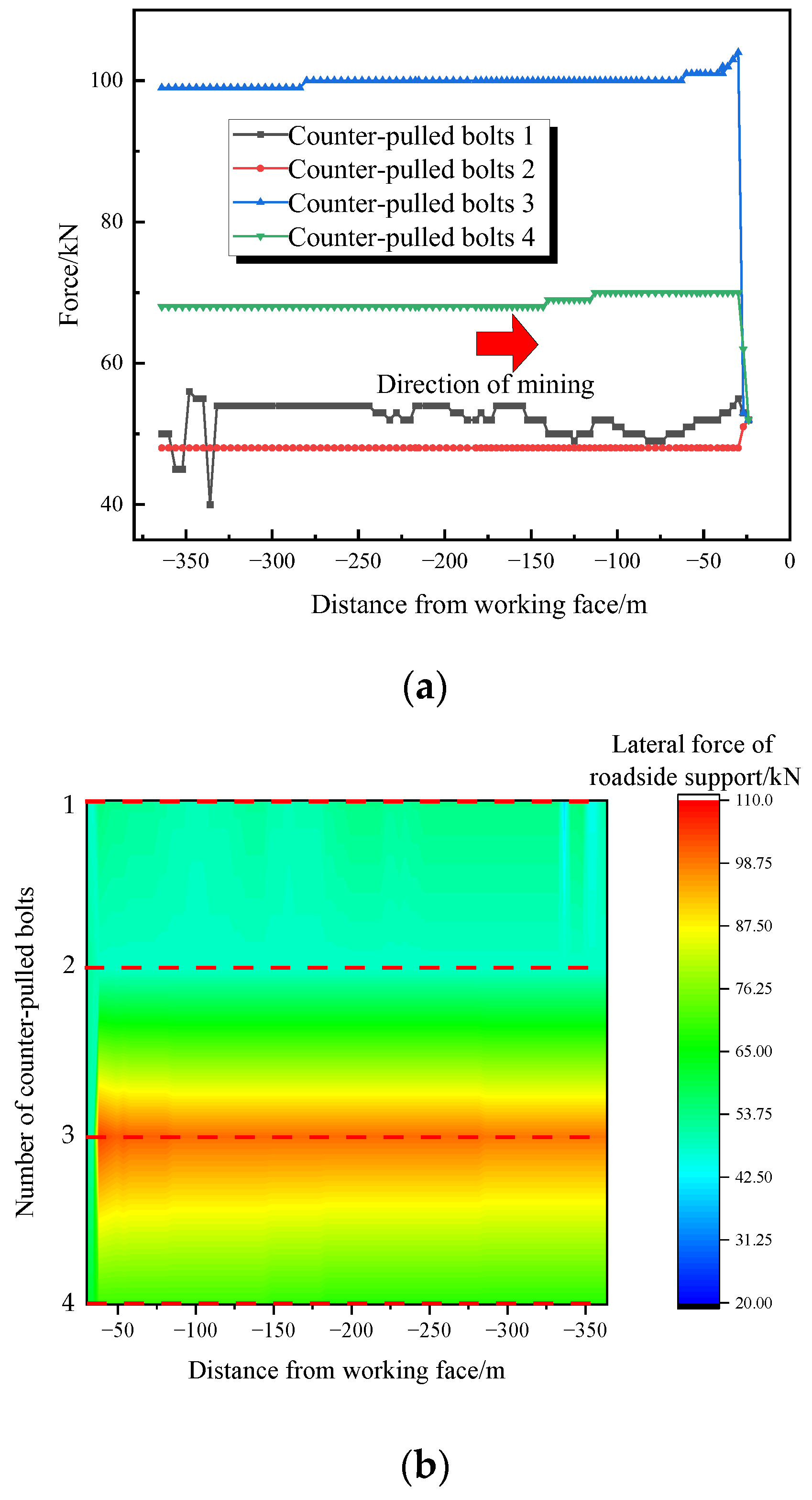
The arrangement of lateral force sensors in the roadside support is shown in Figure 19. After the initial prestressing, the maximum lateral force of the roadside support was found to be 115 kN, which is less than its yield load, and the force is stable. From the lateral force curve and distribution in Figure 20, it can be seen that the overall force state of the reinforced thin concrete roadside support is stable. In addition, the lateral force of the roadside support’s counter-pulled bolts increases rapidly under the action of the roof pressure after prestress. This indicates that the roadside support can realize high strength and high stiffness in time while adapting to the deformation of the roof, and the support structured composed of a flexible formwork, a reinforcement mesh, pallets, and counter-pulled bolts realizes a high-strength lateral restraint in the roadside support. The load of the roadside support can therefore be effectively transferred to the lower part of the roadside support through the overall deformation. The lateral force peak in the middle and lower part of the roadside support, and the lateral load in the upper part of the wall is continuously adjusted under the action of roof pressure. The roadside support presents non-uniform lateral force characteristics as a whole.
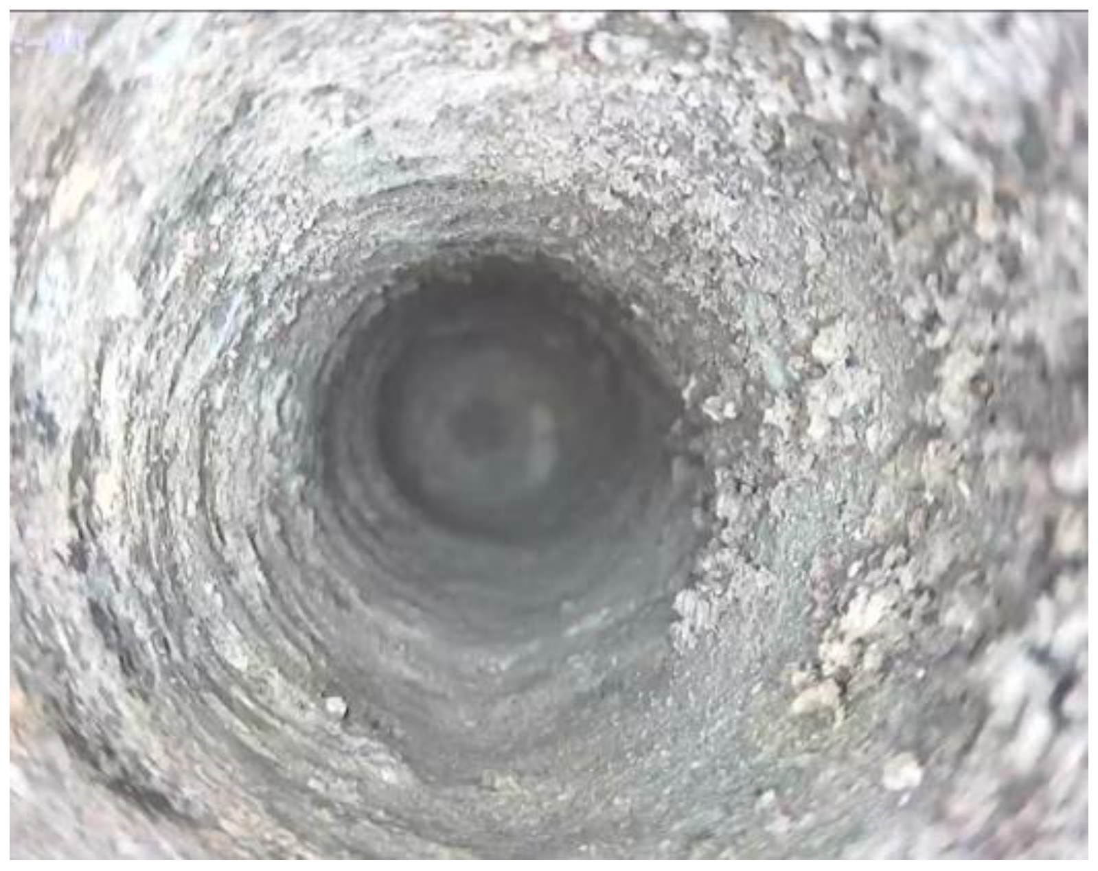
The internal structures of the middle and upper parts of the roadside support were drilled and peeped, as shown in Figure 21. The internal part of the roadside support was basically intact and did not split or break during while adapting to roof deformation.

5.6. Cable Stress Characteristics

As shown in Figure 22, the trend of overall change in the top and side cables’ working resistance was similar. The top cable and the side cable are affected by the sinking of the roof and the lagging mining pressure after the workings are mining, and the support resistance increases faster. The maximum working resistances of the top and side cables are 275 kN and 320 kN, respectively, which are less than the maximum breaking load of 607 kN designed for the cables. The cables with anchor meshes and steel belts have an effective a supporting capacity, control the deformation of the coal side and roof, and increase the residual strength and integrity of the shallow fractured surrounding rock.

5.7. Overall Effect of Gob-Side Entry Retaining

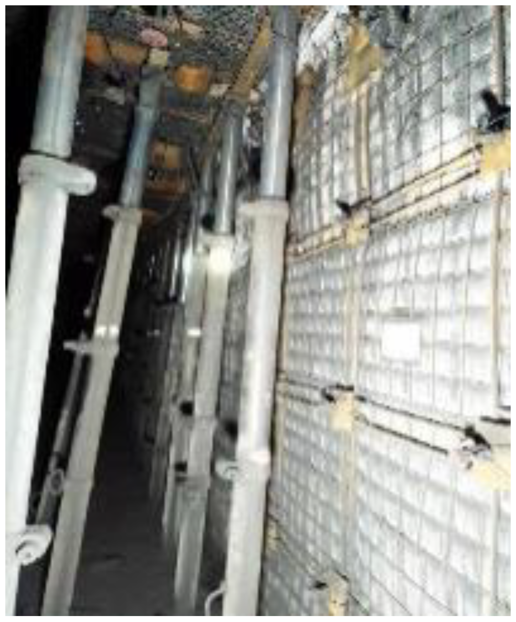
After the length of gob-side entry retaining exceeds 300 m, the maximum roadway shrinkage rate is less than 20%, which can fully meet the requirements of ventilation, gas extraction, material transportation, and reuse. In addition, the roadside support is stable and complete, without splitting damage or tilting. After the lagging cables and channel steel reinforcement are installed, the sinking of the top coal is also effectively controlled. The overall effect is shown in Figure 23, and the monitoring results show that the deformation of the surrounding rock of the 3310 mining face can be effectively controlled under the existing support and pressure relief technology scheme.

6. Conclusions

(1)
The investigated gob-side entry retaining in a mining face experiencing top-coal caving had typical “asymmetric” overall deformation damage characteristics. In addition, the top coal was sinking along the inner side of the roadside support, the concrete roadside support structure was skewing and showing splitting damage, the floor was heaving, and the coal side bolt support structure was losing its support ability and was bulging out of the coal side as a whole.
(2)
The dominant factors of deformation damage are water disintegration of the floor mudstone, deflection deformation under horizontal stress, splitting damage in the concrete roadside support under asymmetric load, damage and expansion due to the insufficient strength of the coal side support, the strong dynamic pressure of the roof, and the mutual influence of support and pressure relief.
(3)
Based on the analysis of the dominant factors of the deformation of the surrounding rocks, a new high-strength, high-stiffness, and high-ductility roadside support structure was designed, and the latest advanced horizontal long borehole regional fracturing pressure relief technology using a large displacement water pump was applied to the lateral roof structure of the gob-side entry retaining to relieve pressure. Together with the steel-cable and belt reinforcement support of the roof inner the roadway, the top-cutting control reinforcement support in the gob-side entry retaining, setup entry hydraulic fracturing pressure relief, and innovative synergistic support and pressure relief scheme to control large deformations in gob-side entry retaining was finally formed. The effect of the industrial test results show that the new roadside support structure significantly optimizes the mechanical properties of the concrete roadside support, the regional pressure relief scheme effectively optimizes the stress environment of gob-side entry retaining space, the deformation control effect of surrounding rock is remarkable, and the gob-side entry retaining fully meets the reuse requirements.

Author Contributions

Conceptualization, H.Y. and D.W.; methodology, H.Y., D.W. and C.S.; writing—original draft, H.Y.; writing—review and editing, H.Y. and W.J.; validation, H.Y. and W.Y.; funding acquisition, D.W. and W.J.; data curation, H.Y. All authors have read and agreed to the published version of the manuscript.

Funding

This research was funded by Innovation Fund Project of CCTEG Coal Mining Research Institute, (KCYJY-2022-MS-01). This support is greatly acknowledged and appreciated.

Institutional Review Board Statement

Not applicable.

Informed Consent Statement

Not applicable.

Data Availability Statement

Not applicable.

Conflicts of Interest

The authors declare no conflict of interest.

References

  1. Wang, Q.; He, M.; Yang, J.; Gao, H.; Jiang, H.; Yu, H. Study of a no-pillar mining technique with automatically formed gob-side entry retaining for longwall mining in coal mines. Int. J. Rock Mech. Min. Sci. 2018, 110, 1–8. [Google Scholar] [CrossRef]
  2. Ma, Q.; Tan, Y.; Zhao, Z.; Xu, Q.; Wang, J.; Ding, K. Roadside support schemes numerical simulation and field monitoring of gob-side entry retaining in soft floor and hard roof. Arab. J. Geosci. 2018, 11, 563. [Google Scholar] [CrossRef]
  3. Zhang, Z.; Shimada, H.; Qian, D.; Sasaoka, T. Application of the retained gob-side gateroad in a deep underground coalmine. Int. J. Min. Reclam. Environ. 2016, 30, 371–389. [Google Scholar] [CrossRef]
  4. Ishwar, S.G.; Kumar, D. Application of DInSAR in mine surface subsidence monitoring and prediction. Curr. Sci. 2017, 112, 46–51. [Google Scholar] [CrossRef]
  5. Kan, J.; Zhang, N.; Wu, J.; Wu, H. Effect of main roofs fracture position on the secondary gob-side entry retaining stability. Disaster Adv. 2013, 6, 189–199. [Google Scholar]
  6. Zhang, Y.; Xu, H.; Song, P.; Sun, X.; He, M.; Guo, Z. Stress evolution law of surrounding rock with gob-side entry retaining by roof cutting and pressure release in composite roof. Adv. Mate. Sci. Eng. 2020, 2020, 1961680. [Google Scholar] [CrossRef]
  7. Li, H. Control design of roof rocks for gob-side entry. Chin. J. Rock Mech. Eng. 2000, 19, 651–654. [Google Scholar]
  8. Jaouhar, E.; Li, L.; Aubertin, M. An analytical solution for estimating the stresses in vertical backfilled stopes based on a circular arc distribution. Geomech. Eng. 2018, 15, 889–898. [Google Scholar]
  9. Venticinque, G.; Nemcik, J.; Ren, T. A new fracture model for the prediction of longwall caving characteristics. Int. J. Min. Sci. Technol. 2014, 24, 369–372. [Google Scholar] [CrossRef]
  10. Zhen, E.; Gao, Y.; Wang, Y.; Wang, S. Comparative study on two types of non-pillar mining techniques by roof cutting and by filling artificial materials. Adv. Civ. Eng. 2019, 2019, 5267240. [Google Scholar]
  11. Li, H.; Zu, H.; Zhang, K.; Qian, J. Study on filling support design and ground pressure monitoring scheme for gob-side entry retention by roof cutting and pressure relief in high-gas thin coal seam. Int. J. Environ. Res. Public Health 2022, 19, 3913. [Google Scholar] [CrossRef] [PubMed]
  12. Xie, S.; Wang, E.; Chen, D.; Li, H.; Jiang, Z.; Yang, H. Stability analysis and control technology of gob-side entry retaining with double roadways by filling with high-water material in gently inclined coal seam. Int. J. Coal Sci. Technol. 2022, 9, 52. [Google Scholar] [CrossRef]
  13. Xie, S.; Wang, E.; Chen, D.; Sun, Y.; Cheng, Q.; Ji, C.; Yan, Z.; Xiao, H. Failure analysis and control mechanism of gob-side entry retention with a 1.7-m flexible-formwork concrete wall: A case study. Eng. Fail. Anal. 2020, 117, 104816. [Google Scholar] [CrossRef]
  14. Du, Z.; Chen, S.; Ma, J.; Guo, Z.; Yin, D. Gob-side entry retaining involving bag filling material for support wall construction. Sustainability 2020, 12, 6353. [Google Scholar] [CrossRef]
  15. Liu, X.; Hua, X.; Yang, P.; Huang, Z. A study of the mechanical structure of the direct roof during the whole process of non-pillar gob-side entry retaining by roof cutting. Energy Explor. Exploit. 2020, 38, 1706–1724. [Google Scholar] [CrossRef]
  16. He, M.; Ma, X.; Yu, B. Analysis of strata behavior process characteristics of gob-side entry retaining with roof cutting and pressure releasing based on composite roof structure. Shock Vib. 2019, 2019, 2380342. [Google Scholar] [CrossRef] [Green Version]
  17. Xie, W.; Da, J.; Feng, G. Mechanism of controlliing surrounding rock around gob-side entry retaining in top-caol caving mining face. J. Cent. South Univ. Sci. Tech. 2004, 35, 5. [Google Scholar]
  18. Yuan, L. Theory and practice of integrated pillarless coal production and methane extraction in multiseams of low permeability. Eng. Sci. 2009, 11, 72–80. [Google Scholar]
  19. Zhang, N.; Han, C.; Kan, J. Theory and practice of surrounding rock control for pillarless gob-side entry retaining. Chin. Coal Soc. 2014, 39, 1635–1641. [Google Scholar]
  20. Kang, H.; Niu, D.; Zhang, Z.; Lin, J.; Li, Z.; Fan, M. Deformation characteristics of surrounding rock and supporting technology of gob-side entry retaining in deep coal mine. Chin. J. Rock Mech. Eng. 2010, 29, 977–1987. [Google Scholar]
  21. Bai, J.; Zhang, Z.; Wang, X. Stress control and surrounding rock strengthening mechanismof gob-side entry retaining with high-water content material filling and its application. Coal Sci. Technol. 2022, 50, 16–28. [Google Scholar]
  22. He, M.; Gao, Y.; Yang, J. An energy-gathered roof cutting technique in no-pillar mining and its impact on stress variation in surrounding rocks. Chin. J. Rock Mech. Eng. 2017, 36, 1314–1325. [Google Scholar]
  23. He, M.; Wang, Y.; Yang, J. Zonal characteristics and its influence factors of working face pressure using roof cutting and pressure-relief mining method with no pillar and roadway formed automaticil. J. Chin. Univ. Min. Techn. 2018, 47, 1157–1165. [Google Scholar]
  24. Gao, Y.; Wang, Y.; Yang, J.; Zhang, X.; He, M. Meso- and macroeffects of roof split blasting on the stability of gateroad surroundings in an innovative nonpillar mining method. Tunn. Undergr. Space Technol. 2019, 90, 99–118. [Google Scholar] [CrossRef]
  25. Li, Y.; Hua, X. The stability of key block and calculating the width of roadside backfill in a secondary gob-side entry retaining. J. Min. Saf. Eng. 2012, 29, 783–789. [Google Scholar]
  26. Li, Y.; Hua, X. Mechanical anlysis on the stability of surrounding rock structure of gob-side entry retaining. J. Chin. Coal Soc. 2017, 42, 8. [Google Scholar]
  27. Wang, D.; Yang, H.; Yuan, W. “Support and pressure relief” ground control technology for double-used roadway with fully-mechanized caving method in thick coal seam. J. Min. Strat. Contr. Eng. 2022, 4, 043014. [Google Scholar]
Figure 1. Roadway layout graph of working face 3310.
Sustainability 15 00739 g001
Figure 2. Comprehensive histogram of rock layers in 3 panel.
Sustainability 15 00739 g002
Figure 3. Original support of gob-side entry retaining.
Sustainability 15 00739 g003
Figure 4. Deformation of gob-side retaining.
Sustainability 15 00739 g004
Figure 5. Measure of gob-side entry retaining deformation. (a) Bulge out of the coal side; (b) Floor heave; (c) Splitting damage in roadside support; (d) Top coal sinking along the inner side of the roadside support.
Sustainability 15 00739 g005
Figure 6. Blast drilling layout of 3303 roadway.
Sustainability 15 00739 g006
Figure 7. High-strength reinforced thin concrete roadside support.
Sustainability 15 00739 g007
Figure 8. Schematic diagram of 3310 roadway support.
Sustainability 15 00739 g008
Figure 9. Schematic diagram of the drilling arrangement of the setup entry hydraulic fracturing.
Sustainability 15 00739 g009
Figure 10. Horizontally oriented long borehole hydraulic fracturing process. (a) Principle of hydraulic fracturing; (b) Hydraulic fracturing tools.
Sustainability 15 00739 g010
Figure 11. 3310 Schematic diagram of horizontally oriented long borehole.
Sustainability 15 00739 g011
Figure 12. Schematic diagram of the wireless mine pressure monitoring and transmission system.
Sustainability 15 00739 g012
Figure 13. Hydraulic bracket stress contour and stress curve of the working face. (a) Stress on the front column of the hydraulic bracket; (b) Stress on the rear column of the hydraulic bracket; (c) The average value of the stress on the front and rear columns of the bracket.
Sustainability 15 00739 g013
Figure 14. Hydraulic bracket working resistance distribution along the working face inclination direction. (a) First measurement; (b) Second measurement.
Sustainability 15 00739 g014
Figure 15. Deformation curves of gob-side entry retaining. (a) formation of the surrounding rock at the location of the 12# roadside support; (b) Deformation of the surrounding rock at the location of the 20# roadside support; (c) Deformation of the surrounding rock at the location of the 45# roadside support.
Sustainability 15 00739 g015
Figure 16. Monitoring scheme of drilling stress.
Sustainability 15 00739 g016
Figure 17. Curves and contour of drilling stress. (a) Curves of drilling stress; (b) Contour of drilling stress.
Sustainability 15 00739 g017
Figure 18. Strength test results of the rebound hammer.
Sustainability 15 00739 g018
Figure 19. Layout of lateral force sensors for roadside support.
Sustainability 15 00739 g019
Figure 20. Lateral force of roadside support. (a) Curves of lateral force; (b) Contour of lateral force.
Sustainability 15 00739 g020
Figure 21. Internal peeping of roadside support.
Sustainability 15 00739 g021
Figure 22. Curve of working resistance of cable.
Sustainability 15 00739 g022
Figure 23. Effect of gob-side entry retaining.
Sustainability 15 00739 g023
Disclaimer/Publisher’s Note: The statements, opinions and data contained in all publications are solely those of the individual author(s) and contributor(s) and not of MDPI and/or the editor(s). MDPI and/or the editor(s) disclaim responsibility for any injury to people or property resulting from any ideas, methods, instructions or products referred to in the content.