Article

Performance Assessment of Three Latent Heat Storage Designs for a Solar Hot Water Tank

Mechanical Engineering Department, College of Engineering, Jazan University, Jazan 45142, Saudi Arabia
*
Author to whom correspondence should be addressed.
Sustainability 2023, 15(1), 640; https://doi.org/10.3390/su15010640
Submission received: 16 November 2022 / Revised: 7 December 2022 / Accepted: 21 December 2022 / Published: 30 December 2022

Abstract

:
Solar hot water tanks (SHWT) based on a latent heat storage system are gaining momentum for their integration into solar heater water collectors. They can efficiently store daytime solar thermal energy and shift on-peak period loads to off-peak periods. However, their performance is generally limited by the tank configuration, the design of the thermal storage system, and the selection of the appropriate phase change material (PCM). This work presents a numerical investigation of three SHWT-PCM storage designs. A mathematical model was developed to predict the effectiveness of the geometric design and operating conditions in the SHWT-PCM system. Moreover, a sensitivity analysis was performed on the PCM type and PCM thermo-physical properties. The obtained numerical results demonstrated that the energy efficiency of the SHWT-PCM system was significantly impacted by the PCM thermo-physical properties (melting temperature, thermal conductivity, and enthalpy). In addition, it was found that using encapsulated PCM tubes with an external PCM jacket in the SHWT can result in a thermal efficiency of 70%.

1. Introduction

The present energy scenario is easily analyzed by the rapid depletion of fissile fuels as well as greenhouse gas emissions, which is alarming for alternative energy solutions. One of the solutions considered is the proper use of renewable energy sources. Electrical energy consumption in buildings, especially for air conditioning and water heating loads, uses about two-thirds of the total energy demands [1]. Therefore, it is essential to limit energy consumption in buildings. Shifting a portion of the electricity consumption from the on-peak period’s electricity demand to the off-peak period could have significant economic, environmental, and social impacts. Among renewable energies, solar energy has the highest potential [2]. This energy source presents storage challenges, as thermal storage can take the form of sensible or latent heat. Storing solar thermal energy during surplus periods and reusing this heat over other nightly periods of the shortfall would improve the performance of this system as well as enhance the operation of the solar water heaters. Integrating thermal energy storage via latent heat thermal energy is a promising technology to transfer on-peak load periods to off-peak load periods. Thermal energy storage systems can be easily integrated with building a wall, solar water collectors, and domestic hot water tanks. The production of domestic hot water is a major concern, particularly the impact of the energy efficiency, size, and volume of the storage tanks [3]. The integration of phase change materials (PCMs) makes it possible to provide solutions using latent heat instead of sensible heat to store thermal energy. Thus, this work mainly concerns the detailed study of heat transfer within water heaters with various designs, with a numerical [4] and experimental [5] approach. By integrating a solar water heater into a latent heat storage system, the most important and common designs are (i) employing PCM capsules in the water tank that conventional solar collectors power, (ii) employing the use of a conventional solar collector with the addition of a separate PCM unit, and (iii) adopting integrated solar collectors and PCMs [2]. Combining solar thermal energy with latent heat storage systems gives an intriguing solution in a more efficient manner.
The analysis and modeling of solar collectors have been of greatest interest in earlier studies. In their detailed studies, Sharma et al. [3] summarized the importance of storage systems with PCMs and their advantages in solar building insulation and aerospace. They also presented new approaches for the measurement of latent heat and melting temperatures. A comparison of different types of storage systems with PCMs was also presented. Kurklu et al. [4] produced a new type of solar collector with 2 parts: 1 with water and 1 with a PCM melting point between 45 and 50 °C. Their experimental results showed that the reservoir temperature was able to maintain 30 °C during the nighttime and daytime with sunshine. Additionally, the instantaneous thermal efficiency values ranged between 22% and 80%. Zalba [5] studied the various types of PCMs and reported a wide choice of MCP. It was noted that the materials were available since they listed more than 150 used and 45 marketed materials. The advantages of systems with PCMs were listed, such as the high equivalent specific heat due to the phase change or the possibility of maintaining the temperature of the water. They identified various problems such as the stability, the lifespan, a reduction in the storage capacity depending on the operating cycle, and toxic risks during fire incidents. Eames and Griffiths [6] developed a model in finite volumes and the collector’s transient regime and heat storage in a self-storing collector using water for different proportions by PCMs. The melting temperature was between 58 and 60 °C. Eames and Griffiths [6] noticed that when the tank temperature was lower than the melting temperature, the solar system’s efficiency with a PCM was lower compared to a system filled with water only. Plantier [7] studied a water tank with PCM spheres. The author showed that using a PCM increases the storage density and makes it possible to limit the temperatures within the tank, improving the design of the system. One of the problems pointed out by Plantier is the poor thermal conductivity produced by the PCM. In his case study, the size of the spheres was too large to provide efficient extraction. This problem was undertaken by Haillot et al. [8]. It was explained experimentally and numerically by integrating a PCM/graphite mixture as a storage medium. In view of the higher thermal conductivity and higher storage capacity of graphite, it extracts more solar energy. It was also reported that the efficiency is reduced by around 98% at the time of withdrawal, showing the higher discharge capacity of the system. Other benefits include reducing the stagnation temperatures and storage space. Mettaweea et al. [9] investigated the performance of a compact solar-PCM collector system. From their work, it is observed that the average heat transfer coefficient increases with an increase in the molten paraffin layer thickness due to natural convection. Many industries are focusing on the solid–liquid phase change problem and the use of numerical solution methods. Lacroix et al. [10] overcame this problem in their investigation. They studied the thermal energy storage system experimentally and analytically using cylindrical tubes as storage materials. In addition to that, Laouadi et al. [11] conducted a numerical study based on the melting and solidification cycle of the PCM n-eicosane created by Bayomy et al. [12] for household hot water. According to the findings, the system is capable of 39% efficiency. Klçkap S. et al. [13] investigated a thermal energy storage (TES) tank used in an S.W.H. tank. According to their investigation, the S.W.H.-PCM tank showed an efficiency of 58%. A redesign process was used by Harris B. et al. [14] to improve an existing TES with a PCM system for an S.W.H. tank. According to their findings, the revised TES achieved a minimum water temperature of 45.3 °C with a thermal efficiency of 76.08%. Numerous researchers have studied and reported the results of various designs of storage units for different locations of the PCM, materials used, and system configurations [15]. At present, for integrating a separate latent heat storage system, the solutions available are either traditional solar water heaters or integration in the auto-storage collectors [16,17]. However, in view of high heat losses, these solutions are unsatisfactory from a thermal point of view as well as aesthetic point of view. This is why, within this study, an innovative solution aimed at integrating a latent heat storage system into the water storage tank allows for complete system integration and reduces heat losses [18,19]. Using PCMs rather than traditional water storage might make sense in order to increase the solar system’s autonomy [20]. However, care should be used when selecting PCMs [21]. The melting range of the fitted PCM should be comparable to the temperatures attained in the storage tank [22]. Two critical points should be considered in designing an SHWT: the stable requirement temperature of the domestic SHWT during daytime [23] and the assurance of a complete melting/solidification process to reach the maximum energy storage and release [24,25]. The objectives of the present work are to (i) study three designs of solar hot water tank with the integration of a latent heat storage unit to match solar energy availability to heat requirements, (ii) develop a mathematical model to assess the suitability of the PCM storage unit designs with the solar hot water tank, and (iii) perform a parametric analysis of the SHWT based on the PCM’s thermo-physical properties.

2. Description of the Three SHWT Designs

As shown in Figure 1, the solar water heater collector includes a thermal solar absorber which absorbs solar radiation and transforms it into thermal energy. A heat transfer fluid (HTF) heats up while passing through the solar collector tubes and goes to a water storage tank. The spiral heat exchanger transfers its solar calories to the domestic water. The primary circuit transports the heat, and it is sealed, insulated, and contains water with added antifreeze. The cooled fluid is finally returned to the solar collector, where it is heated again as long as the sunshine remains effective.
The solar hot water tank (SHWT) is a tank that constitutes the domestic water reserve. The cold water from the secondary circuit replaces the hot water withdrawn, which will again be heated by the HTF from the primary circuit.
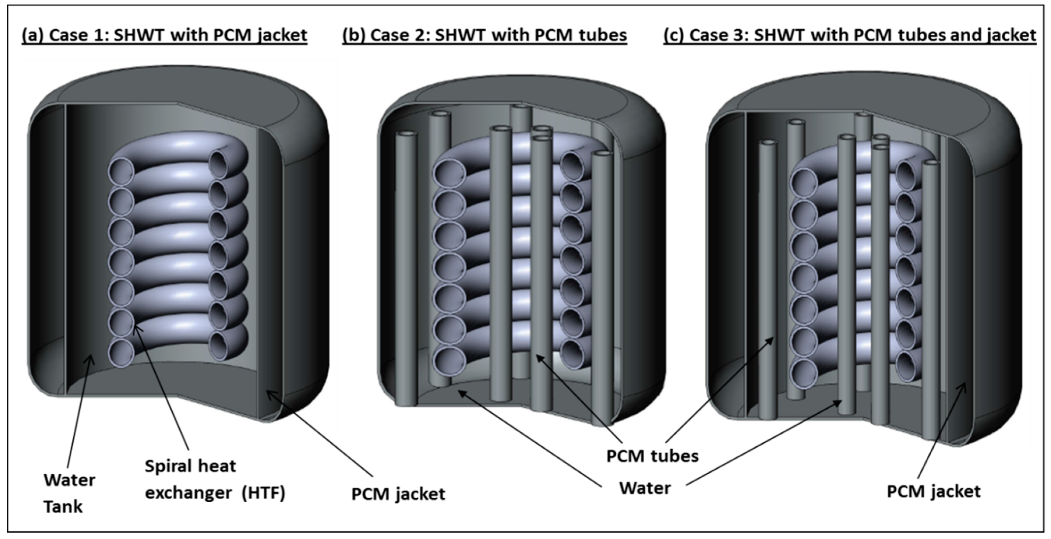
Figure 2 shows the three designs of the SHWT-PCM system:
(i)
Design 1: consists of a cylindrical tank which is integrated to a central spiral heat exchanger tube. The spiral tube is further connected to a solar thermal collector which converts the solar radiation into thermal energy. This thermal energy is then used to heat an HTF that passes through the spiral tube inside the water tank. The heat collected by the solar collector passes through a tube via an HTF to a spiral-type heat exchanger located in the SHWT. The HTF then gives up its calories to the domestic water before returning, once cooled, to the collector to be heated as long as the sunshine allows it. During bad weather, extra energy takes over. A heat accumulator, which is connected to the SHWT and PCM, is contained in an external jacket that stores the thermal energy while passing from a solid state to a liquid state. The PCM jacket changes phase when the solar collector begins to be overproduced. The energy is then restored when the need arises. This system thus makes it possible to increase the storage capacity without increasing the volume of the water tank. Its application is, therefore, effective in overcoming the intermittent solar energy utilization problem.
(ii)
Design 2: consists of a cylindrical tank integrated with a central spiral heat exchanger tube. The spiral tube is connected to a solar thermal collector. The SHWT is integrated with twelve encapsulated PCM tubes.
(iii)
Design 3: similar to design one and design two, the SHWT is equipped with an external PCM jacket and integrated with twelve encapsulated PCM tubes.

3. Mathematical Model

A mathematical model was developed using energy conservation and momentum equations, to analyze the performance of the SHWT-PCM systems. The three SHWT-PCM systems consist of different domains, namely water, HTF, and PCM. The following assumptions are made for the development of the model:
(i)
constant thermo-physical properties
(ii)
the wall’s thermal resistance is negligible.
(iii)
the fluid is incompressible fluid
The governing equations are expressed based on the prior assumptions.

3.1. Continuity Equation

The continuity equation is expressed as follows:
ρ t + d i v ρ V = 0
where ρ and V denote the liquid’s density and velocity, respectively.

3.2. Momentum Equation

The momentum equation is expressed as follows:
ρ V t + ρ . V V = p + μ 2 V + ρ r e f g 1 α . T T r e f + S
where p denotes pressure, μ is the liquid’s dynamic viscosity, ρ r e f is the liquid’s density, g is the gravity vector, α is the thermal expansion coefficient, Tref denotes the reference temperature (the initial water tank temperature), and S is the source term.

3.3. Energy Equations

For water
ρ C P D T D t = k 2 T
where C P denotes specific heat, k denotes thermal conductivity, and T denotes temperature.
For PCM
From the energy equation, the enthalpy was calculated, which is the sum of its sensible enthalpy (h) and latent heat (Δh). The corresponding energy equations are given below:
t ρ h + . ρ V h = . k T
Where h and k represent the total enthalpy and the thermal conductivity, respectively. The total enthalpy can be expressed using the following equation, h:
h = h r e f + T r e f T C p d T + f L
where href denotes the enthalpy of phase change at the reference temperature (Tref) and L refers to the latent heat of phase change.
The liquid fraction (f) of the PCM is defined below.
f = 0 T T S T S T l 1 s i T T s o l i d u s s i T s o l i d u s T T l i q u i d u s s i T l i q u i d u s T
The temperature solution is obtained by iterating the energy Equation (4) and liquid fraction (f) Equation (6)

3.4. The HTF Temperature

The HTF temperature is to be considered as variable throughout the day and is presented by Salman H. et al. [13]. This plot can be used to determine the HTF temperature equation as a function of time. This is the polynomial equation of order nine and the coefficients are given in Table 1:
T H T F ( t ) = a 0 + a 1 t + a 2 t 2 + + a 9 t 9

3.5. The Storage Efficiency of the SHWT-PCM System

To analyze the heat storage efficiency of the SHWT-PCM system, the heat storage efficiency was calculated by the following equation.
η S H W T = Q re Q st
where Qst and Qre are the stored thermal and total released energy, respectively.
The stored thermal energy of the SHWT-PCM system is expressed by:
Q st = m T 0 T m C p , s d T + m f Δ H + m T m T a C p , l d T
The released thermal energy of the SHWT-PCM system is expressed by
Q re = m T 0 T m C p , l i q d T + m f Δ H + m T m T a C p , s o l i d d T
where m is the mass of the PCM, Tm is the melting temperature, T0 is the initial temperature of the PCM, and Ta is the average temperature of the PCM at the end of the melting process.

3.6. Initial and Boundary Conditions

The following initial and boundary conditions are applied to the present work:
(i)
The temperatures of the PCM, HTF, and water are uniform
(ii)
The external wall thickness of the SHWT-PCM system is thermally insulated,
(iii)
The HTF temperature is variable with time, as expected in Equation (7),
(iv)
The domain interface is thermally insulated.

4. Simulation Method and Model Validation

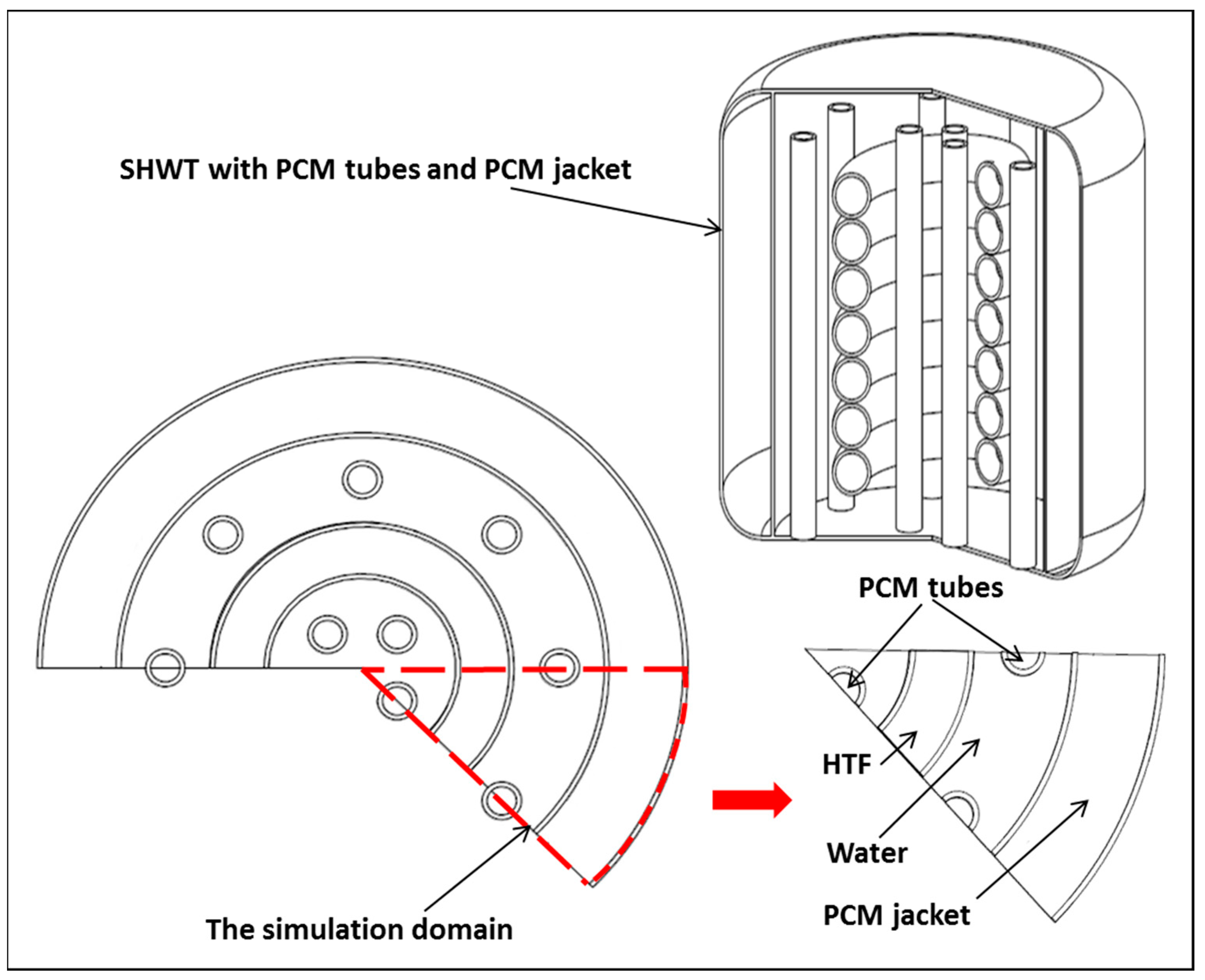
The general form of the computational domain of the three SHWT-PCM designs is illustrated in Figure 3. For simplification, only 1/8 of the domain was simulated.
The finite volume method was used to simulate the physical model with the Fluent 6.3 software. The meshing of the SHWT-PCM system configuration was performed using Gambit software.
Under similar operating conditions, the numerical values of the physical mode were compared with results of open literature [16]. Figure 4 shows the comparison between the simulation data with literature results and good agreement is achieved with comparative results. Hence, the developed model in the present study is considered as a reliable and acceptable one.

5. Results and Discussion

The numerical study was made for the three SHWT-PCM tank designs. Each water tank is integrated with a spiral heat exchanger, which circulates HTF previously heated by a solar collector and allows it to be at a variable inlet temperature (Equation (7)).

5.1. Performance of the Three SHWT-PCM Tank Designs

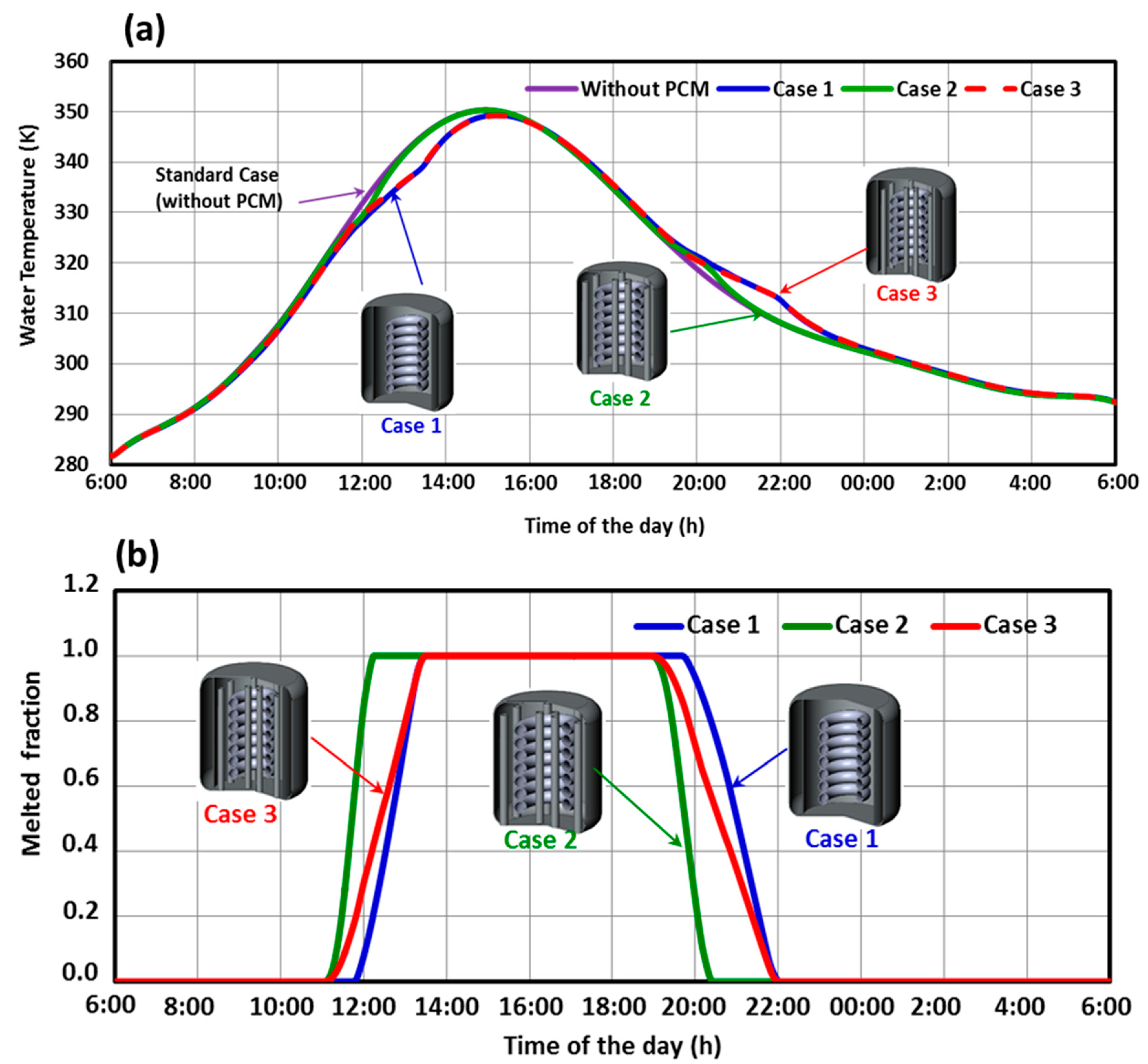
The comparison of the three SHWT-PCM storage designs is shown in Figure 5. The water temperature evolutions in the three SHWT-PCM storage designs during a storage/release cycle are depicted in Figure 5. The water temperature of the three cases are compared to the case without a PCM as a reference. Initially, we can note from Figure 5a that four identical curve shapes are exhibited. Additionally, we can observe a phase shift between the 3 profiles, and that corresponds to the temperature without a PCM, which reaches a maximum value (351 K) approximately at 14 h:30. In contrast, the second corresponds to the temperature in case 3, which reaches a maximum value (350 K) at about 15 h. The difference in temperature particularly in three cases are proportional to the amount of heat stored. A phase shift is seen on rising temperature curves due to the PCM energy storage. For the discharge process, Figure 5a indicates that the water temperature decreases gradually and slightly in comparison to the case without a PCM. This effect is due to the phase change (solidification) process, which releases stored heat during the day, resulting in a delay in the temperature decrease.
Design 3 is better because as the hotter HTF is introduced into the spiral heat exchanger, more heat is stored in the PCM-encapsulated tubes and the PCM jacket, increasing the heat transfer between the HTF and the water.
Figure 5b shows the result of the PCM melted fraction of the three SHWT-PCM designs during a storage/release cycle. The evolution of the PCM liquid fraction for each case can be divided into three parts, where the first part shows the storage of energy by PCM through sensible heat. In the second, the temperature is fixed during phase change and the PCM stores a large quantity of heat and the third one is similar to first part but the PCM is in liquid. It is also noticed that when the solar radiation is present between 6 a.m. and 11.30 a.m., the liquid fraction is constant, indicating that it is a sensible storage, since the PCM’s temperature is lower than the melting point. It is also observed that during the period of 11:30 a.m. to 1:15 p.m., the temperature of the tank reaches the melting point of the PCM where it is completely melted when the liquid fraction reaches the value of 1 and remains constant till 7.00 p.m. (sensible storage). This can be explained by the small temperature difference between the tank and the PCM. When the SHWT starts cooling, the solidification process begins in parallel and the fraction value decreases rapidly, reaching zero value (PCM in solid condition). Finally, the liquid fraction remains constant between 10:00 p.m. and 6:00 a.m., which indicates the thermal equilibrium condition.
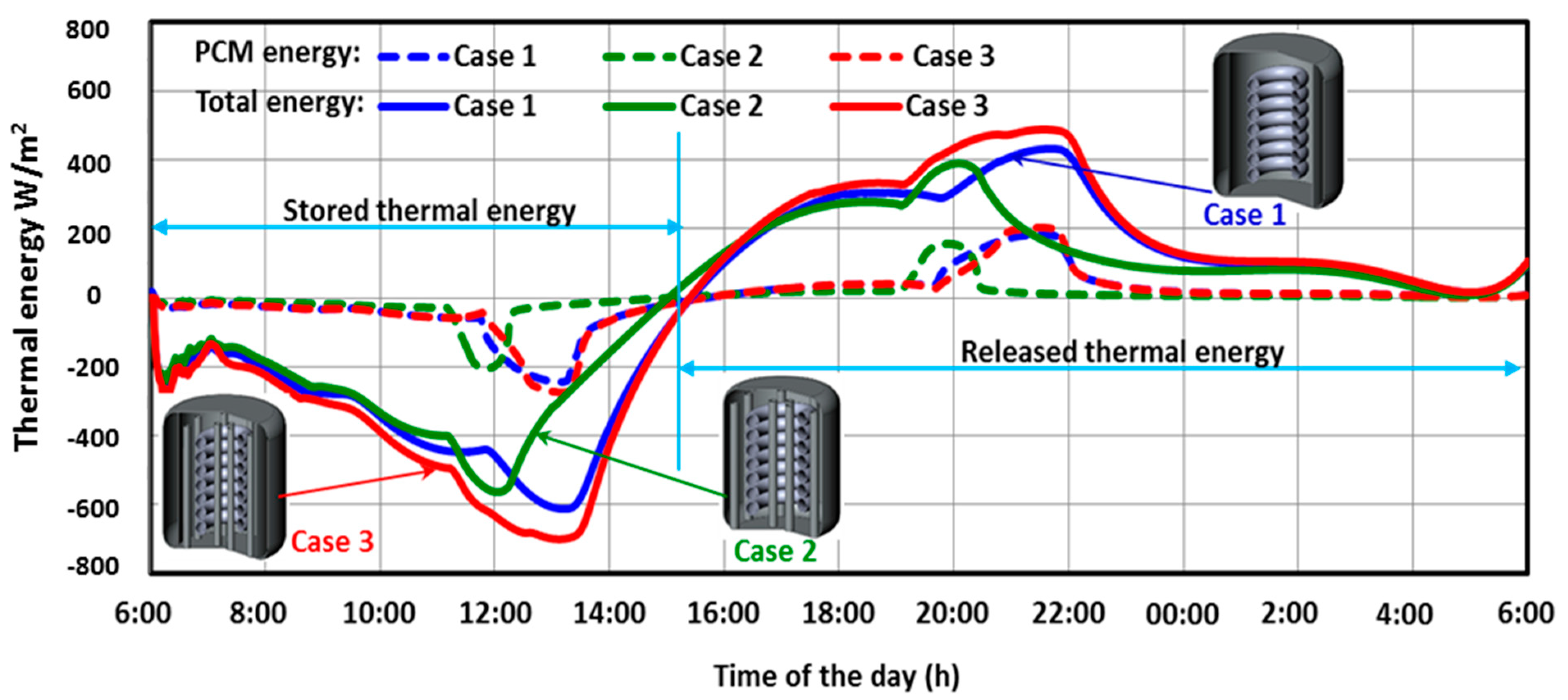
Figure 6 shows the storage of thermal energy in the three SHWT-PCM tank designs. The comparison of the amount of thermal energy stored/released in the 3 designs can appear clearly in Figure 6, where the evolution of the thermal energy stored in case 3 was more than that in another case. From Figure 6, it is essential to note that the amount of thermal energy brought into play in the phase change process is much more significant than during sensitive transfers. Thanks to these latent transfers, it is now possible to considerably reduce the volume of an energy storage system or even significantly increase the quantity of energy contained in the same storage volume.
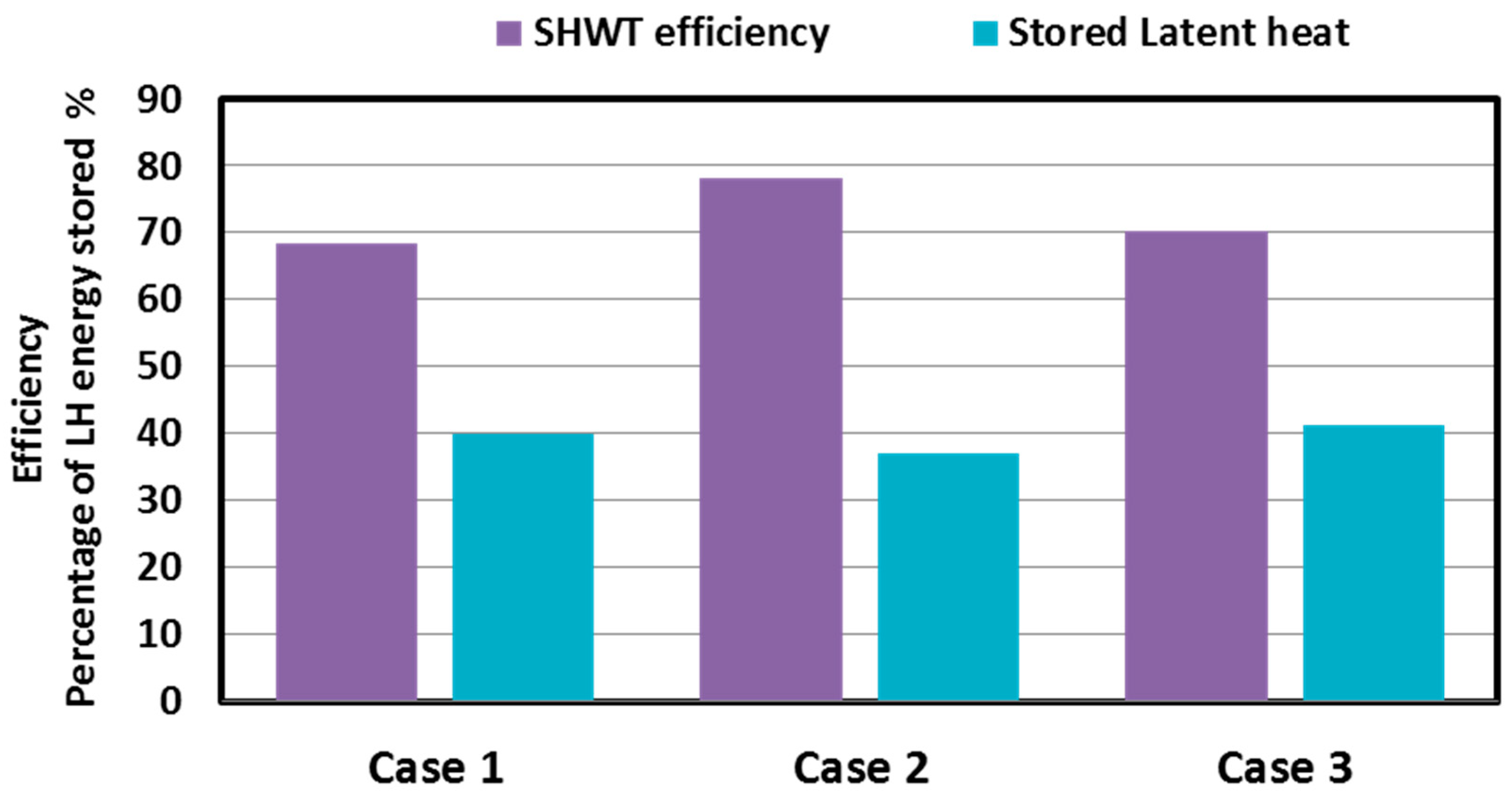
To quantify the thermal storage efficiency, Figure 7 shows the percentage of latent heat stored in each thermal energy storage tank during the charging period and the thermal efficiency of the three designs. It was observed that, under the same conditions, the thermal efficiency of case 1 is 69%, and for case 2, the thermal efficiency is 79%. In addition, for case 3, the thermal efficiency is 70%. The 3 designs used the whole store of energy, and because of the integration of the PCM tubes and jacket in case 3, a significant portion of the latent heat energy (41%) was stored by case 3. As a result, the thermal storage efficiency was decreased by up to 70% compared to case 2.

5.2. Effect of the PCM Type

Different PCM types were tested to improve the storage system’s thermal efficiency. There are four PCM types whose thermodynamic criteria represent an interesting choice for the comparative study. Table 2 presents the thermo-physical properties of the PCMs used. The influence of PCM type on water temperature and average OCM melted fraction are shown in Figure 8. From the obtained results, PCM2 presented a more interesting option than the other PCMs. It is noticed that PCM2 makes it possible to maintain a higher hot water temperature during the discharge process. The maintenance of the higher water temperature depends on the thermal energy available in the SHWT containing the PCMs and was also examined from an energy efficiency point of view. It is shown that the stored thermal energy is destroyed less quickly in the case of the SHWT containing PCM2, which led to a better quality of thermal energy storage material. The PCM2 paraffin wax changes phase at a temperature of 40°C and with higher enthalpy, which makes it possible to store a greater quantity of energy in latent form. Its high heat capacity and thermal conductivity provide an additional sensible heat storage effect.

5.3. Effect of PCM Thermo-Physical Properties

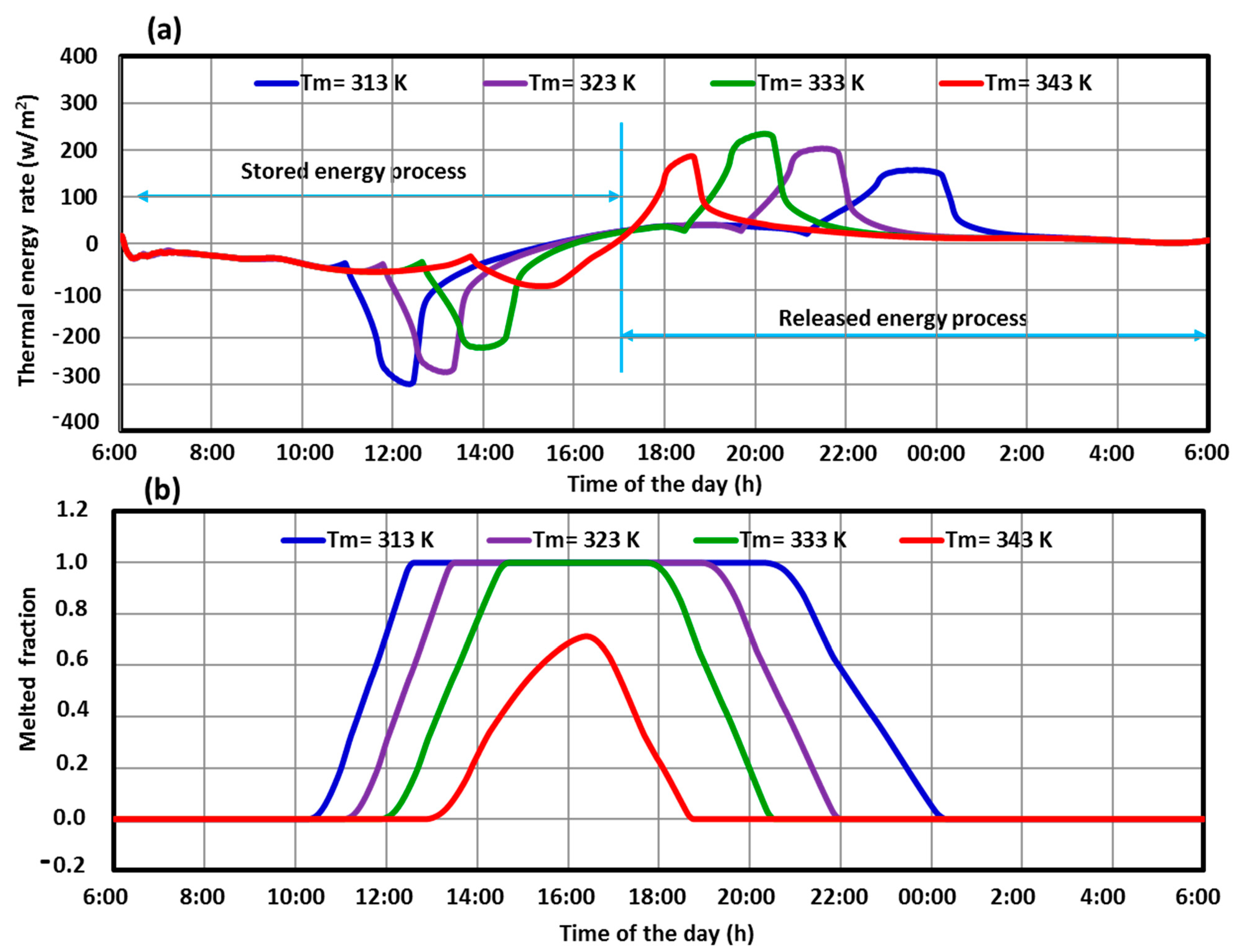
Figure 9 shows the effect of melting temperatures with thermal energy stored/released and the average PCM melted fraction. In the morning session, PCMs with higher melting temperatures are heated, requiring an enormous amount of heat to reach their melting temperature. They then melt into a liquid while keeping the PCM temperature constant. On the other hand, the PCMs with a lower melting temperature requires less heat to melt, and stores sensible heat. During the evening, when the temperature drops, the PCMs which have a higher melting temperature solidify rapidly, and the stored latent heat is released more quickly compared to the PCMs which have a lower melting temperature.
From Figure 9a, it is found that the lower melting temperature is measured for a longer duration of the shifting period. Moreover, from Figure 9b, the PCM melting temperature directly affects the total duration of the melting process but not the sensible heat transfer rate. Moreover, not being able to raise the PCM melting temperature indefinitely risks storing most of the heat in a sensible form. On the other hand, it is possible to keep most of this heat in a latent condition. However, there is a limit to raising the melting temperature of the PCM. For example, a PCM melting temperature of around 313 K is suitable for this system.
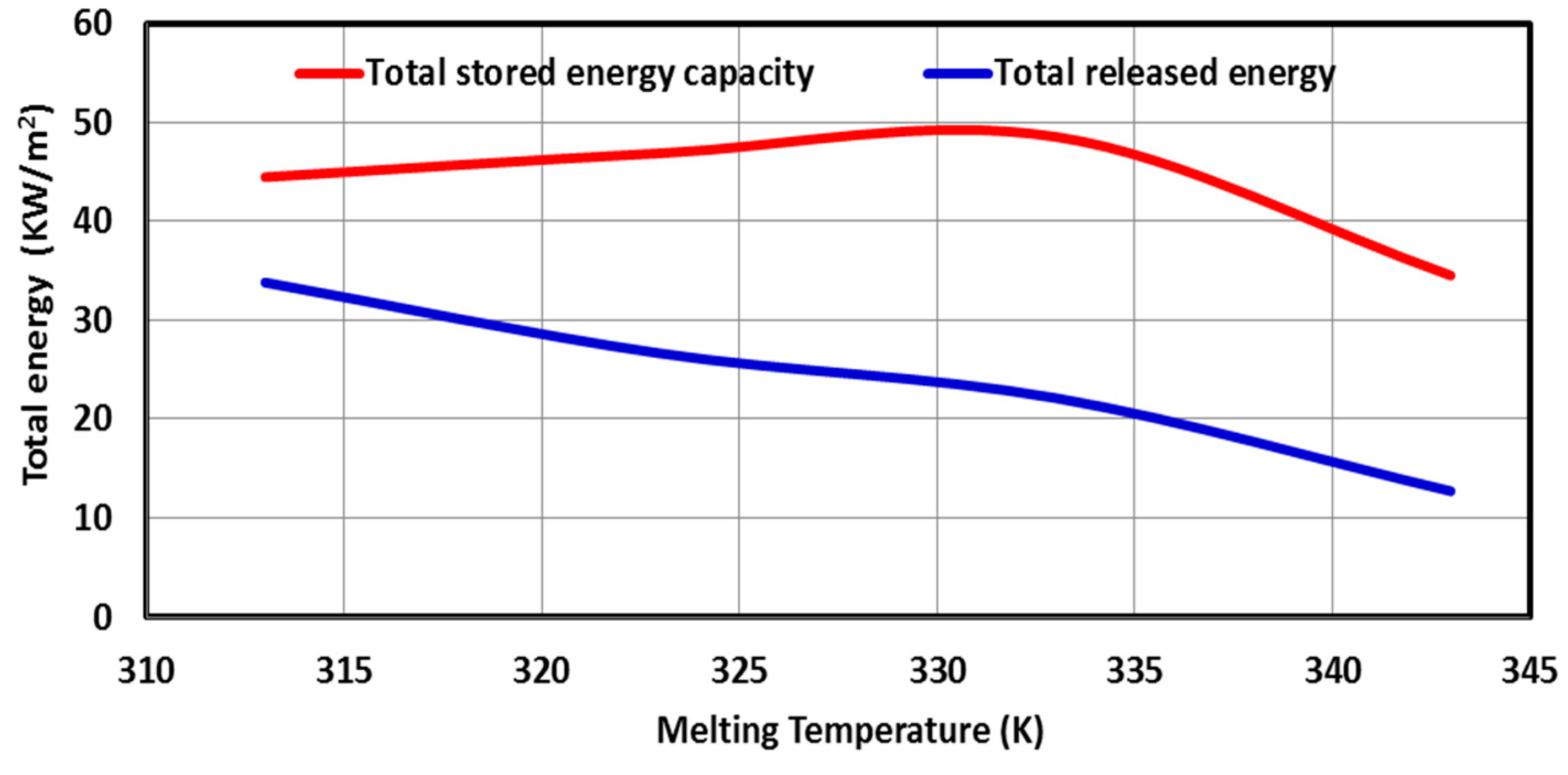
Figure 10 shows the effect of the melting temperature on thermal energy storage. From Figure 10, it is seen that the optimum melting temperature is around 313 K.
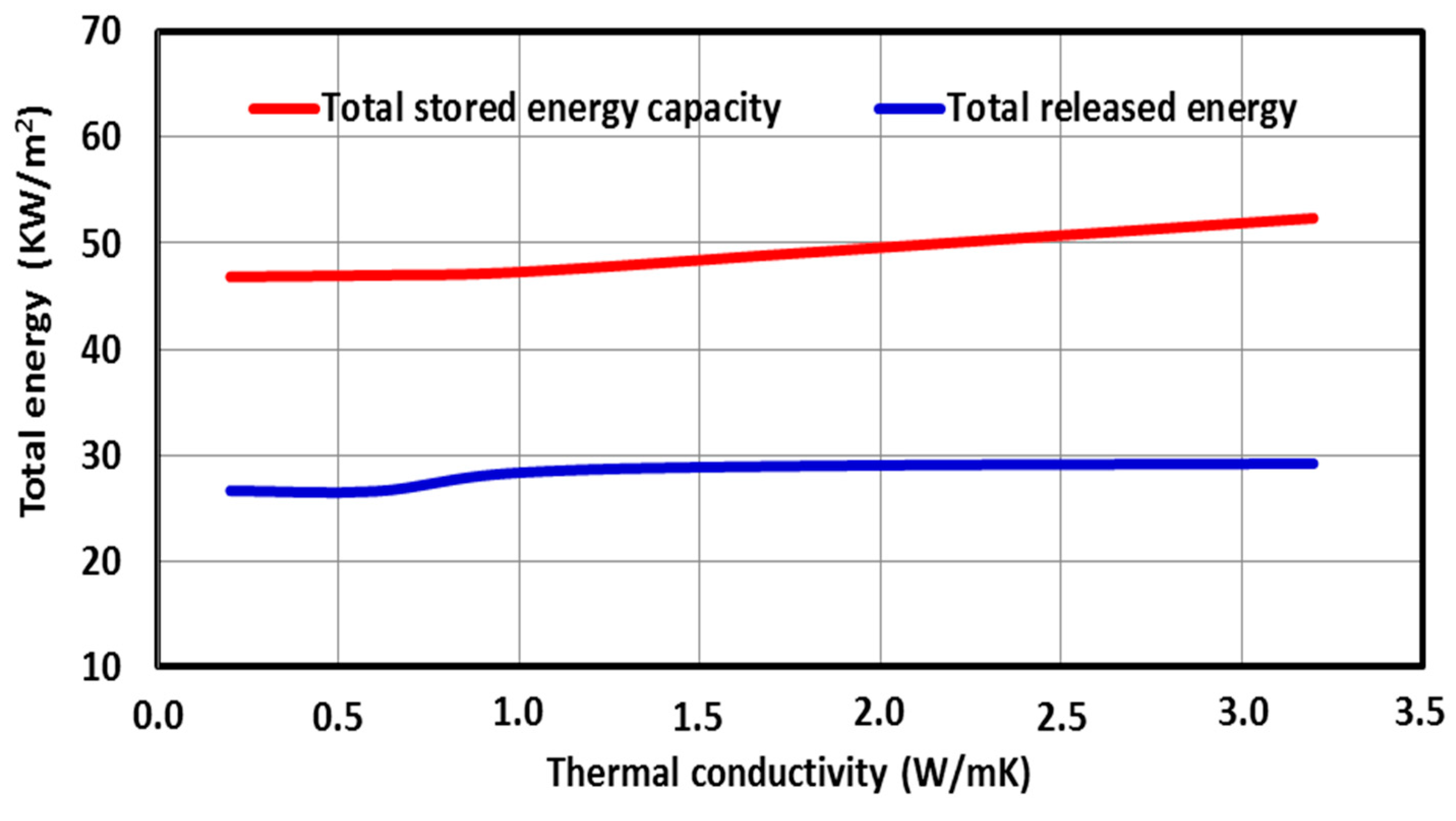
Figure 11 shows the evolution of (a) the thermal energy storage/release and (b) the PCM melted fraction for different thermal conductivities (0.2, 0.6, 1, 1.8, and 3.2 W/m.K) during a complete cycle (storage/release). Figure 11a presents the variations of the thermal energy transferred to/from the PCM, and Figure 9b illustrates the PCM melted fraction’s evolution as a time function. From this figure, we notice that the amount of heat stored by the PCM is proportional to the PCM thermal conductivity, and as a consequence of the amount of stored energy which can be shifted as an increase in thermal conductivity, generates an increase in the amount of thermal energy provided by the PCM, which enhances the fusion process of the PCM as depicted in Figure 11b.
Figure 12 depicts the effect of thermal conductivity on the thermal energy stored/released from the system. From Figure 12, it is essential to note that the thermal conductivity value affects the amount of thermal energy stored/released.
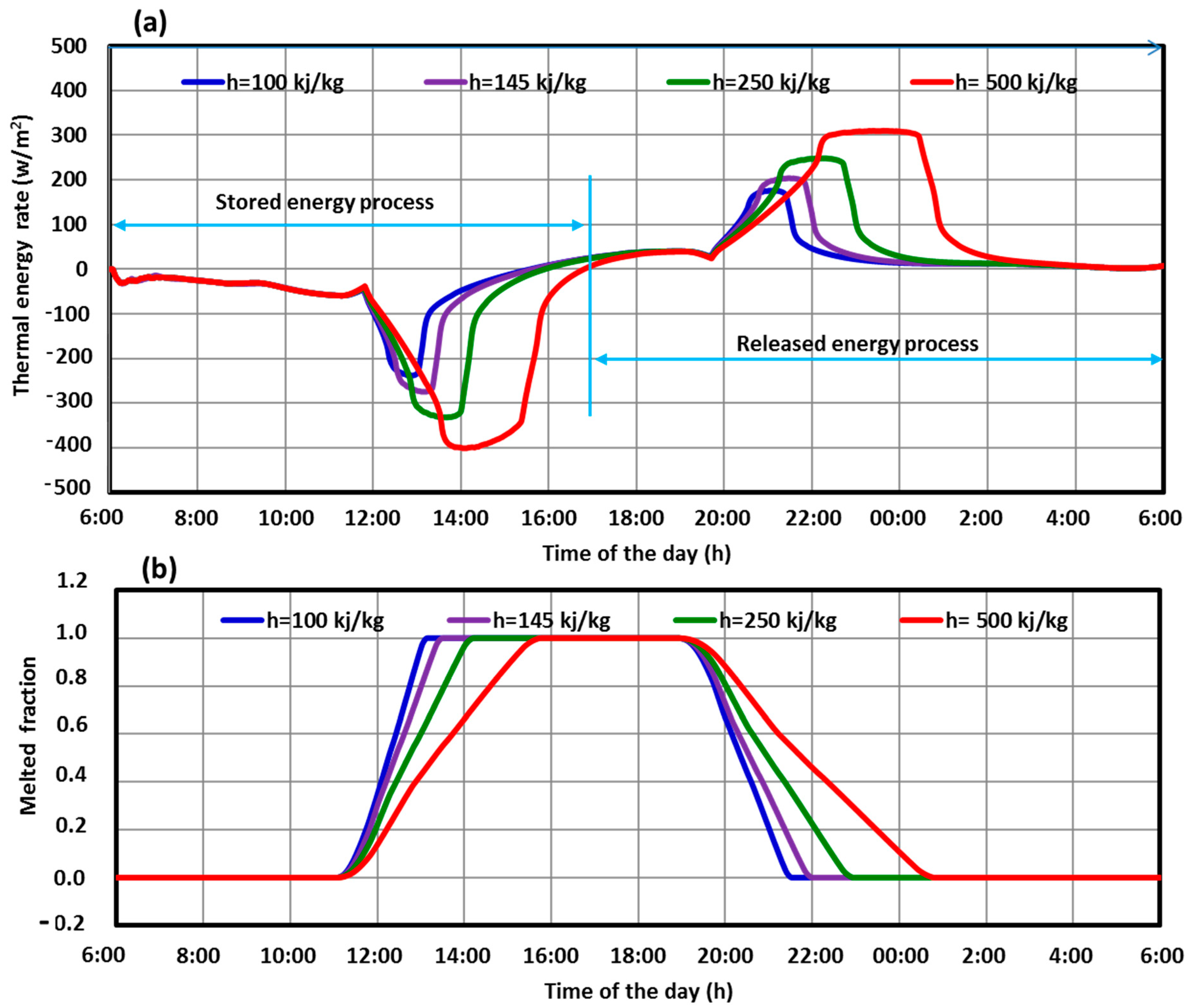
Figure 13 shows the evolution of (a) the thermal energy storage/release and (b) the melted fraction for different latent heat enthalpies (100, 145, 250, and 500 Kj/kg) during a complete cycle (storage/release).
Figure 13a shows the variation of thermal energy stored/released for various PCM latent heat enthalpies. It is observed that increasing the PCM’s latent heat enthalpy results in an increase in the maximum thermal energy stored/released in the morning and the evening. This is illustrated by the fact that the PCM retains more heat when its enthalpy has a high value, with less heat transfer to the water. The PCM accumulates heat during the day in the storage system and recovers it when necessary in the evening. Its role is, therefore, to delay the availability of solar energy. From Figure 13a, it is seen that the thermal energy stored/released increases with a steep slope from the initial temperature to the PCM melting point. This first mode corresponds to the conductive transfer between the heat transfer fluid and the solid PCM. When the PCM changes phase, thermal energy stored/released for the cases with higher enthalpy continues to increase but with a very slight slope between the start temperature Tsolidus and the end temperature of the change of state Tliquidis. At the end of the state change, the thermal energy stored/released curve undergoes a new inflection and increases up to the maximum value. During the release process, the slope of the thermal energy stored/released curve decreases slightly. There is no solid PCM left at all. The variation of PCM latent heat enthalpy with PCM melted fractions is shown in Figure 13b. Indeed, it was noticed that the melted fraction is faster for lower latent heat enthalpies. This can be illustrated by the fact that a high latent heat enthalpy results in the PCM retaining more heat, resulting in more time in the melting process.
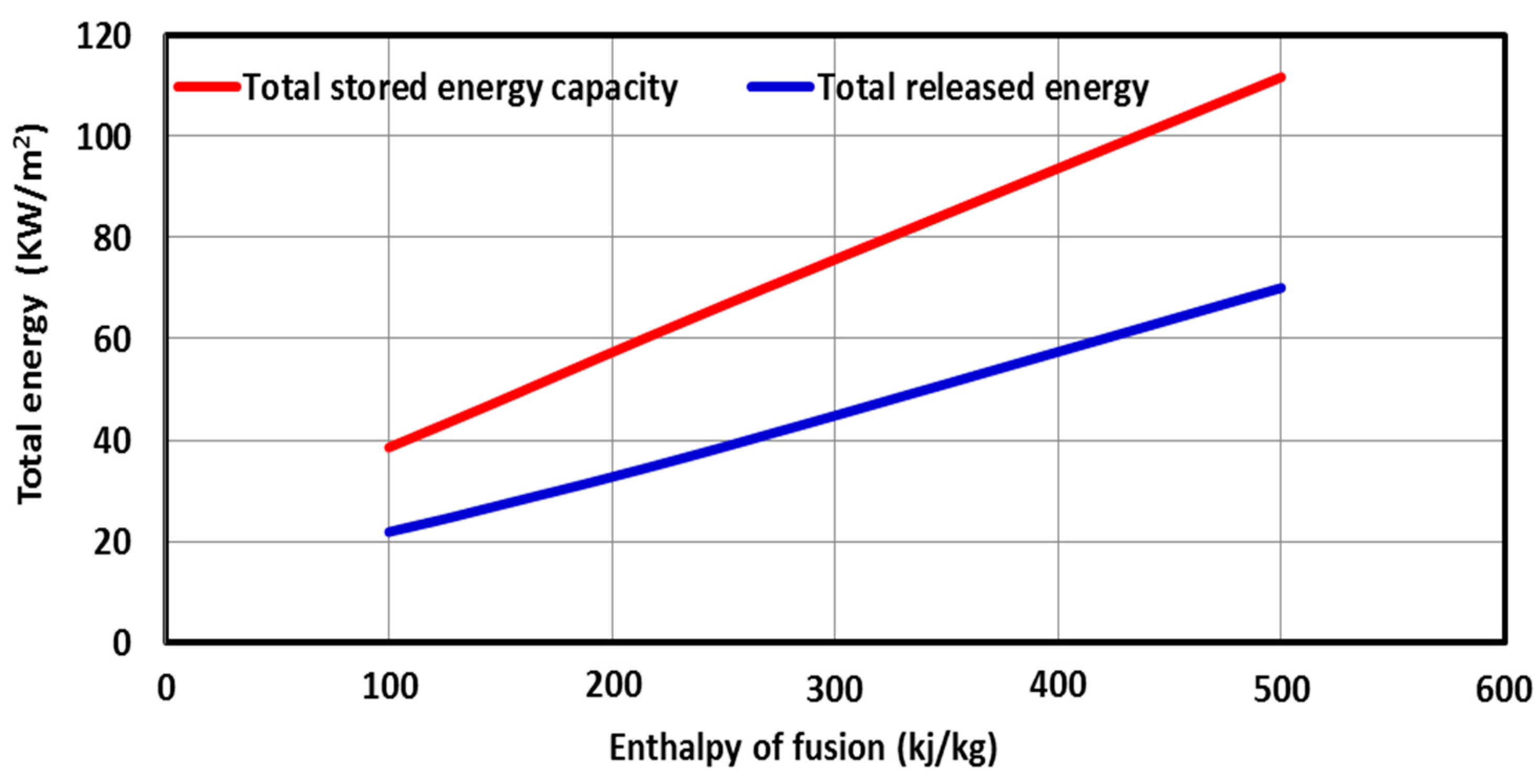
Figure 14 shows the effect of the PCM latent heat enthalpy on the thermal energy stored/released. From Figure 14, it is seen that the thermal energy stored is proportional to the PCM latent heat enthalpy.

6. Conclusions

This study focused on the thermal performance of three solar hot water tank (SHWT) designs integrated with a PCM-based latent heat energy storage system. A two-dimensional mathematical model was developed to simulate the thermal performance effeteness of the three SHWT designs. This study yielded the following conclusions:
The SHWT-PCM system’s design significantly affects the storage process.
With the proposed design (case 3), where the PCM tubes and the PCM jacket are integrated, a higher portion of the latent heat energy (41%) was stored, and the thermal storage efficiency was up to 70%.
The water temperature of the SHWT in case 3 was higher compared to another design. This was caused by the integration of the PCM jacket, which decreases thermal losses by increasing the heat storage and insulation properties of the PCM.
Both the latent heat and the thermal conductivity of the PCM must be as high as possible to quickly store a large amount of thermal energy on-peak period load, which is then shifted to the off-peak period.
An optimum PCM melting temperature can be selected for the better SHWT-PCM system’s thermal performance. The PCM melting temperature value is 333 K, favored when a more extended shifting period is needed.
As future work, the impacts of the operational conditions, especially the HTF mass flow rate, should be further studied to optimize the benefits of integrating latent heat storage PCMs into domestic solar hot water tanks.

Author Contributions

Conceptualization, S.M. and W.Z.; methodology, W.Z.; software, Y.F.; validation, W.Z., S.M. and Y.F.; formal analysis, W.Z.; investigation, W.Z.; resources, W.Z.; data curation, S.M.; writing—original draft preparation, S.M. and W.Z.; writing—review and editing, W.Z.; visualization, S.M.; supervision, F.Y; project administration, Y.F.; funding acquisition, S.M. All authors have read and agreed to the published version of the manuscript.

Funding

This research was funded by the Scientific Research Deanship, Jazan University, Kingdom of Saudi Arabia.

Informed Consent Statement

Not applicable.

Acknowledgments

The authors gratefully acknowledge the Scientific Research Deanship, Jazan University, Kingdom of Saudi Arabia for funding this research work under the grant number W41-050.

Conflicts of Interest

The authors declare no conflict of interest.

Nomenclature

CPheat capacity (kj/kg.K)
Fthe melted fraction of PCM
g the acceleration of gravity (m/s2)
Hthe enthalpy (kj/kg)
Kthe thermal conductivity (W/m.K)
Lthe latent heat (kj/kg)
Ppressure (Pa)
Tthe temperature (K)
V the velocity (m/s)
ρ the density (kg/m3)
μ the dynamic viscosity (Pa s)
Abbreviations:
HTFHeat Transfer Fluid
PCMPhase Change Material
SHWTSolar Hot Water Tank

References

  1. Elarem, R.; Alqahtani, T.; Mellouli, S.; Askri, F.; Edacherian, A.; Vineet, T.; Badruddin, I.A.; Abdelmajid, J. A comprehensive review of heat transfer intensification methods for latent heat storage units. Energy Storage 2020, 3, e127. [Google Scholar] [CrossRef] [Green Version]
  2. Khan, M.M.A.; Ibrahim, N.I.; Mahbubul, I.M.; Ali, H.M.; Saidur, R.; Al-Sulaiman, F.A. Evaluation of solar collector designs with integrated latent heat thermal energy storage: A review. Sol. Energy 2018, 166, 334–350. [Google Scholar] [CrossRef]
  3. Sharma, A.; Tyagi, V.V.; Chen, C.R.; Buddhi, D. Review on thermal energy storage with phase change materials and applications. Renew. Sustain. Energy Rev. 2009, 13, 318–345. [Google Scholar] [CrossRef]
  4. Kürklü, A.; Özmerzi, A.; Bilgin, S. Thermal performance of a water-phase change material solar collector. Renew. Energy 2002, 26, 391–399. [Google Scholar] [CrossRef]
  5. Zalba, B.; Marín, J.M.; Cabeza, L.F.; Mehling, H. Review on thermal energy storage with phase change: Materials, heat transfer analysis and applications. Appl. Therm. Eng. 2003, 23, 251–283. [Google Scholar] [CrossRef]
  6. Eames, P.; Griffiths, P. Thermal behaviour of integrated solar collector/storage unit with 65°C phase change material. Energy Convers. Manag. 2006, 47, 3611–3618. [Google Scholar] [CrossRef]
  7. Plantier, C. Etude Numérique et Expérimentale d’un Prototype de Chauffe- eau Solaire Equipé d’un Stockage à Chaleur Latente. Ph.D. Thesis, ESIGEC—Univérsité de Savoie, Chambéry, French, 2005. [Google Scholar]
  8. Haillot, D.; Goetz, V.; Py, X.; Abdelkarim, M.B. Integrated solar collector storage system based on phase change material and graphite composite. In Proceedings of the 2008, 1st International Congress on Heating, Cooling and Buildings, Lisbon, Portugal, 7–10 October 2008. [Google Scholar]
  9. Mettaweea, E.B.S.; Assassab, G.M.R. Experimental Study of a Compact PCM Solar Collector. Energy 2006, 31, 2958–2968. [Google Scholar] [CrossRef]
  10. Lacroix, M. Study of the Heat Transfer Behavior of Latent Heat Thermal Energy StorageUnit with a Finned Tube. Int. J. Heat Mass Transf. 1993, 36, 2083–2092. [Google Scholar] [CrossRef]
  11. Laouadi, A.; Lacroix, M. Thermal performance of a latent heat energy storage ventilated panel for electric load management. Int. J. Heat Mass Transf. 1999, 42, 275–286. [Google Scholar] [CrossRef]
  12. Bayomy, A.; Davies, S.; Saghir, Z. Domestic Hot Water Storage Tank Utilizing Phase Change Materials (PCMs): Numerical Approach. Energies 2019, 12, 2170. [Google Scholar] [CrossRef]
  13. Kılıçkap, S.; El, C.; Yıldız, E. Investigation of the Effect on the efficiency of phase change material placed in solar collector tank. Therm. Sci. Eng. Prog. 2018, 5, 25–31. [Google Scholar] [CrossRef]
  14. Harris Bernal, I.A.; James Rivas, A.M.; Ortega Del Rosario, M.D.L.A.; Saghir, M.Z. Redesign Methodology to Improve the Performance of a Thermal Energy Storage with Phase Change Materials: A Numerical Approach. Energies 2022, 15, 960. [Google Scholar] [CrossRef]
  15. Farid, M.M.; Husian, R.M. An electrical storage heater using the phase-change method of heat storage. Energy Convers. Mgmt 1990, 3, 219–230. [Google Scholar] [CrossRef]
  16. Hammadi, S.H. Study of solar water heating system with natural circulation in basrah. Al-Qadisiya J. Eng. Sci. 2009, 2, 3. [Google Scholar]
  17. Wu, W.; Dai, S.; Liu, Z.; Dou, Y.; Hua, J.; Li, M.; Wang, X.; Wang, X. Experimental study on the performance of a novel solar water heating system with and without PCM Sol. Energy 2018, 171, 604–612. [Google Scholar]
  18. Algarni, S.; Mellouli, S.; Alqahtani, T.; Almutairi, K.; Khan, A.; Anqi, A. Experimental investigation of an evacuated tube solar collector incorporating nano-enhanced PCM as a thermal booster. Appl. Therm. Eng. 2020, 180, 115831. [Google Scholar] [CrossRef]
  19. Xue, H.S. Experimental investigation of a domestic solar water heater with solar collector coupled phase-change energy storage. Renew. Energy 2016, 86, 257–261. [Google Scholar] [CrossRef]
  20. Saraswat, A.; Bhattacharjee, R.; Verma, A.; Das, M.K.; Khandekar, S. Investigation of diffusional transport of heat and its enhancement in phase-change thermal energy storage systems. Appl. Therm. Eng. 2017, 111, 1611–1621. [Google Scholar] [CrossRef]
  21. Bouhal, T.; El Rhafiki, T.; Kousksou, T.; Jamil, A.; Zeraouli, Y. PCM addition inside solar water heaters: Numerical comparative approach. J. Energy Storage 2018, 19, 232–246. [Google Scholar] [CrossRef]
  22. Koca, A.; Oztop, H.F.; Koyun, T.; Varol, Y. Energy and exergy analysis of a latent heat storage system with phase change material for a solar collector. Renew. Energy 2008, 33, 567–574. [Google Scholar] [CrossRef]
  23. Shukla, A.; Buddhi, D.; Sawhney, R.L. Solar water heaters with phase change material thermal energy storage medium: A review. Renew. Sustain. Energy Rev. 2009, 13, 2119–2125. [Google Scholar] [CrossRef]
  24. Hooshmand, A.; Zahmatkesh, I.; Karami, M.; Delfani, S. Exergy analysis of a nanofluid–based direct absorption solar collector (DASC) occupied by porous foam. Chall. Nano Micro Scale Sci. Technol. 2021, 9, 1–11. [Google Scholar]
  25. Nemati, H.; Javanmardi, M.J. Exergy optimization of domestic solar cylindrical-parabolic cooker. J. Renew. Sustain. Energy 2012, 4, 063134. [Google Scholar] [CrossRef]
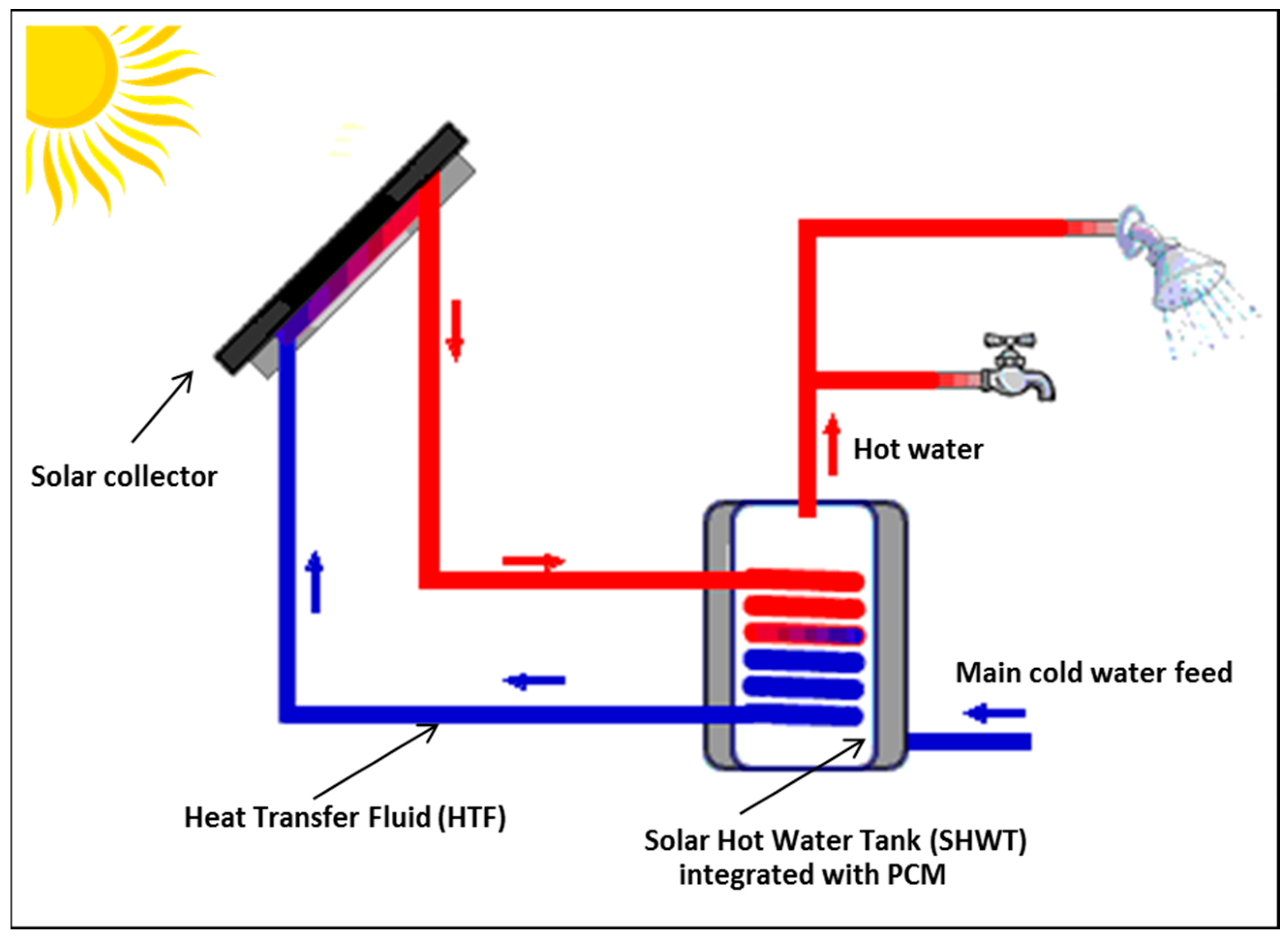
Figure 1. Schematic illustration of the solar water heater collector.
Sustainability 15 00640 g001
Figure 2. The three designs of the SHWT-PCM system.
Sustainability 15 00640 g002
Figure 3. The computational domain of the SHWT with PCM tubes and PCM jacket.
Sustainability 15 00640 g003
Figure 4. Validation of the mathematical model: comparison between the present study results and the results obtained from [13].
Sustainability 15 00640 g004
Figure 5. Comparison of three SHWT-PCM storage designs: (a) the water temperature and (b) the average PCM melted fraction.
Sustainability 15 00640 g005
Figure 6. Thermal energy storage of the three SHWT-PCM tank designs.
Sustainability 15 00640 g006
Figure 7. Thermal efficiency of the three SHWT-PCM tank designs.
Sustainability 15 00640 g007
Figure 8. The Effect of the PCM type on the water temperature and the average PCM melted fraction.
Sustainability 15 00640 g008
Figure 9. The Effect of the melting temperature on (a) the thermal energy rate and (b) the average PCM melted fraction.
Sustainability 15 00640 g009
Figure 10. The Effect of the melting temperature on the thermal energy storage.
Sustainability 15 00640 g010
Figure 11. The Effect of the thermal conductivity on (a) the thermal energy rate and (b) the average PCM melted fraction.
Sustainability 15 00640 g011
Figure 12. The Effect of thermal conductivity on thermal energy storage.
Sustainability 15 00640 g012
Figure 13. The Effect of the PCM enthalpy on (a) the thermal energy rate and (b) the average PCM melted fraction.
Sustainability 15 00640 g013
Figure 14. The Effect of the PCM enthalpy on the thermal energy storage.
Sustainability 15 00640 g014
Table 1. The polynomial coefficients of the HTF temperature equation.
0a1a2a3a4a5a6a7a8a9
281.3160.0025−3.881 × 10−74.60162 × 10−11−1.907 × 10−153.050 × 10⁻²⁰−3.307 × 10⁻²⁶−4.699 × 10−305.27 × 10⁻³⁵−1.814 × 10−40
Table 2. The PCM’s thermophysical properties.
ProprietiesPCM1PCM2PCM3PCM4
Melting point (°C)50404464
Enthalpy of fusion (kj/kg)145174190250
Density (kg/m 3 )1412900930880
Heat capacity (kj/kg.K)2.42.52.12
Thermal conductivity (W/m.K)0.20,210.210.2
Disclaimer/Publisher’s Note: The statements, opinions and data contained in all publications are solely those of the individual author(s) and contributor(s) and not of MDPI and/or the editor(s). MDPI and/or the editor(s) disclaim responsibility for any injury to people or property resulting from any ideas, methods, instructions or products referred to in the content.