Article

Energy Management Strategy for Seaport Integrated Energy System under Polymorphic Network

1
Marine Electrical Engineering College, Dalian Maritime University, Dalian 116026, China
2
Research Institute of Intelligent Networks, Zhejiang Lab, Hangzhou 311121, China
3
Jiaxing Big Data Center, Jiaxing Municipal People’s Government, Jiaxing 314000, China
4
School of Statistics, Beijing Normal University, Beijing 100875, China
*
Author to whom correspondence should be addressed.
Sustainability 2023, 15(1), 53; https://doi.org/10.3390/su15010053
Submission received: 14 October 2022 / Revised: 4 December 2022 / Accepted: 11 December 2022 / Published: 21 December 2022

Abstract

:
This paper studies the energy management problem of a seaport integrated energy system under the polymorphic network. Firstly, with the diversity of energy devices, a seaport integrated energy system based on the polymorphic network is established to ensure information exchange and energy interaction between heterogeneous devices, including the service layer, control layer, and data layer. Secondly, by analyzing the characteristics of different loads and the energy conversion hub, such as the power to gas (P2G) and combined cooling heating and power (CCHP), the energy management model for the seaport integrated energy system is constructed. Finally, we obtain the optimal solution by mixed integer linear programming, and the proposed strategy is used to a seaport integrated energy system including CCHP, P2G, clean energy and energy storage device. By comparing four different cases, the simulation results show a reduction in the cost of energy purchase and carbon emissions when applying our strategy with various device types and device failures. Moreover, considering the application of the proposed energy management strategy under seasonal variations, the optimal solution for the energy management problem of the seaport integrated energy system is obtained.

1. Introduction

As an important hub between sea and land transportation, the carbon emissions of seaports have increased and have become a vital issue in the harbor industry [1]. With the continuous growth of seaport demands, the International Maritime Organization (IMO) proposed the zero-carbon target and aims to decrease the maritime industry’s overall carbon dioxide (CO2) emissions by 50% by 2050 [2]. The seaport integrated energy system is being intensively investigated in order to reduce carbon emissions and increase clean energy utilization [3].
The seaport integrated energy system is proposed to satisfy load demands by analyzing various energy characteristics [4]. Integrated energy system contains a wide range of devices, among which the application of combined cooling heating and power (CCHP), power to gas (P2G) and energy storage system have attracted the widespread attention. Ref. [5] investigates the redundant design of the systems, combining PV cells with CCHP to effectively improve the reliability and availability of the system. An efficient transcritical CO2 CCHP system for recovering low-grade energy is proposed and analyzed in [6]. To achieve a more accurate assessment of the supplied energy, a model of thermal load forecasting with attenuation and transmission delay is built, and a method of feed-forward active operation optimization for CCHP systems is proposed in [7]. Research [8] proposes a low-carbon economic dispatch optimization strategy using a heating network and P2G to accomplish sustainable energy development. Ref. [9] provides a bi-level optimal dispatch model for the integrated energy system with a carbon capture system and P2G facility, which enhances the integrated energy system’s economics as well as the capacity of wind and solar energy accommodation. According to [10], a new idea that combines P2G technology with demand-response technology is proposed and can achieve peak cutting and valley filling. A wind-photovoltaic-hydrogen storage-integrated energy system with the goal of minimizing overall economic and environmental costs is proposed, which could help alleviate the pressure of carbon emissions in some way [11]. To increase new energy consumption and lower carbon emissions, a configuration-scheduling dual-layer optimization model taking energy storage and demand response into account is suggested for the multi-microgrid integrated energy system [12]. In [13], energy storage scenarios that take into account battery or thermal energy storage using HS technology in the combination of the solar array and wind turbine system are provided, suggesting that HS is crucial for ensuring high generation dependability. The above only considers the case of CCHP, P2G, and energy storage systems acting individually in the integrated energy system, but this paper investigates a seaport integrated energy system that includes CCHP, P2G, and energy storage systems operating collaboratively. The seaport integrated energy system contains various energy devices such as electrolyzer (EL) [14], methane reactor (MR) [15], gas turbine (GT) [16]. It also combines multiple energy supply networks such as electrical network, gas network, and heating network [17] to meet load demands such as shore power, refrigerated containers, gas turbines, and ships [18]. Specifically, P2G and CCHP are considered as the energy conversion hub of the system. As mentioned above, the seaport integrated energy system contains heterogeneous energy devices [19], which are produced by different manufacturers with different communication protocols [20]. It is difficult to exchange information between devices under the traditional communication network with a single modality [21], and intelligent energy management can not be realized. The polymorphic network provides the polymorphic presentation of network functions [22], which supports full-dimensional definitions of functions in the seaport integrated energy system such as data forwarding, heterogeneous interconnection, addressing routing, and energy management [23]. Therefore, how to establish a seaport integrated energy system under a polymorphic network should be paid attention to.
Many fundamental issues of seaport integrated energy system have been studied [24]. The energy management problem of the seaport integrated energy system is a critical issue for improving the energy efficiency of the seaport integrated energy system and ensuring its reliable operation. The energy management problem is a complicated optimization problem that includes physical constraints such as energy balance and supply capacity upper bound [25]. Many researchers studied the energy management problem. An energy management problem for a waste heat recovery system was investigated to improve its energy efficiency [26]. A solar seasonal adjustable energy management system was established to achieve the decarbonization goal [27]. In order to satisfy the hydrogen needs of an industrial hydrogen facility, a energy management model for hydrogen was proposed [28]. In [29], an energy management strategy for a community energy supply system including energy storage devices was established to reduce fossil energy waste and guarantee a clean energy supply. In [30], an energy management model of a large wind farm under uncertainty was considered to avoid wind curtailment and load shedding incidents. In [31], a new energy management strategy for the cold storage system was proposed to reduce the overall system payment. The above studies are only adapted to traditional energy systems with a single energy flow. However, the seaport integrated energy system is a multiple energy coupled system, and little investigation considered the energy management problem. A logistics-energy collaborative optimization dispatch strategy for the large seaport integrated energy system was proposed to reduce logistics operating costs [32]. In [33], the energy management models for the belt conveyor and the bunkering system were proposed to solve the general energy-transport scheduling issue for the bulk seaport. The energy management model for the seaport integrated energy system was proposed to meet the operational flexibility needs of reefer area, berth allocation problems, and cold-ironing [34]. However, the above studies do not comprehensively analyze the characteristics of various devices in the seaport integrated energy system. Therefore, it should be further studied to consider how to analyze the characteristics of different devices and establish their energy management model.
To sum up, this paper aims to build a multi-energy flow coupled seaport integrated energy system under a polymorphic network and investigate its energy management problem. The following are the paper’s contributions:
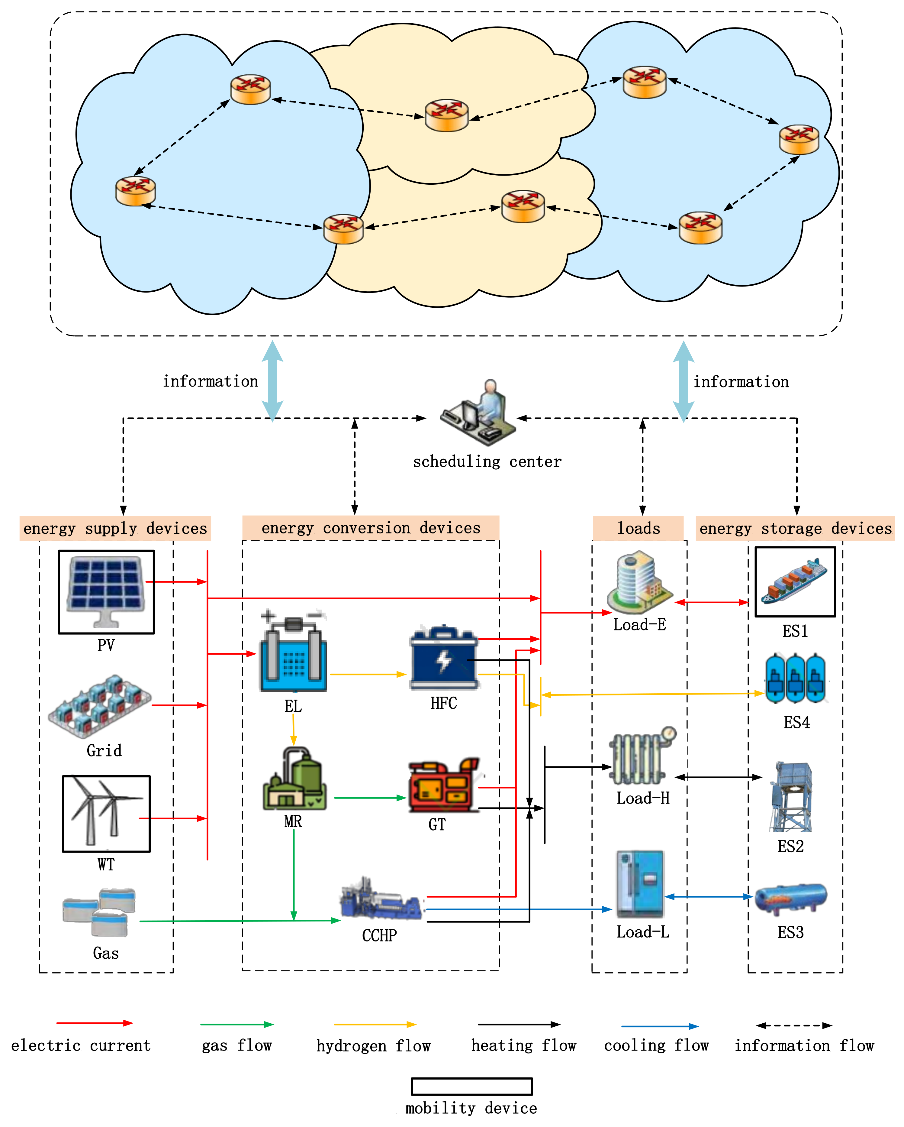
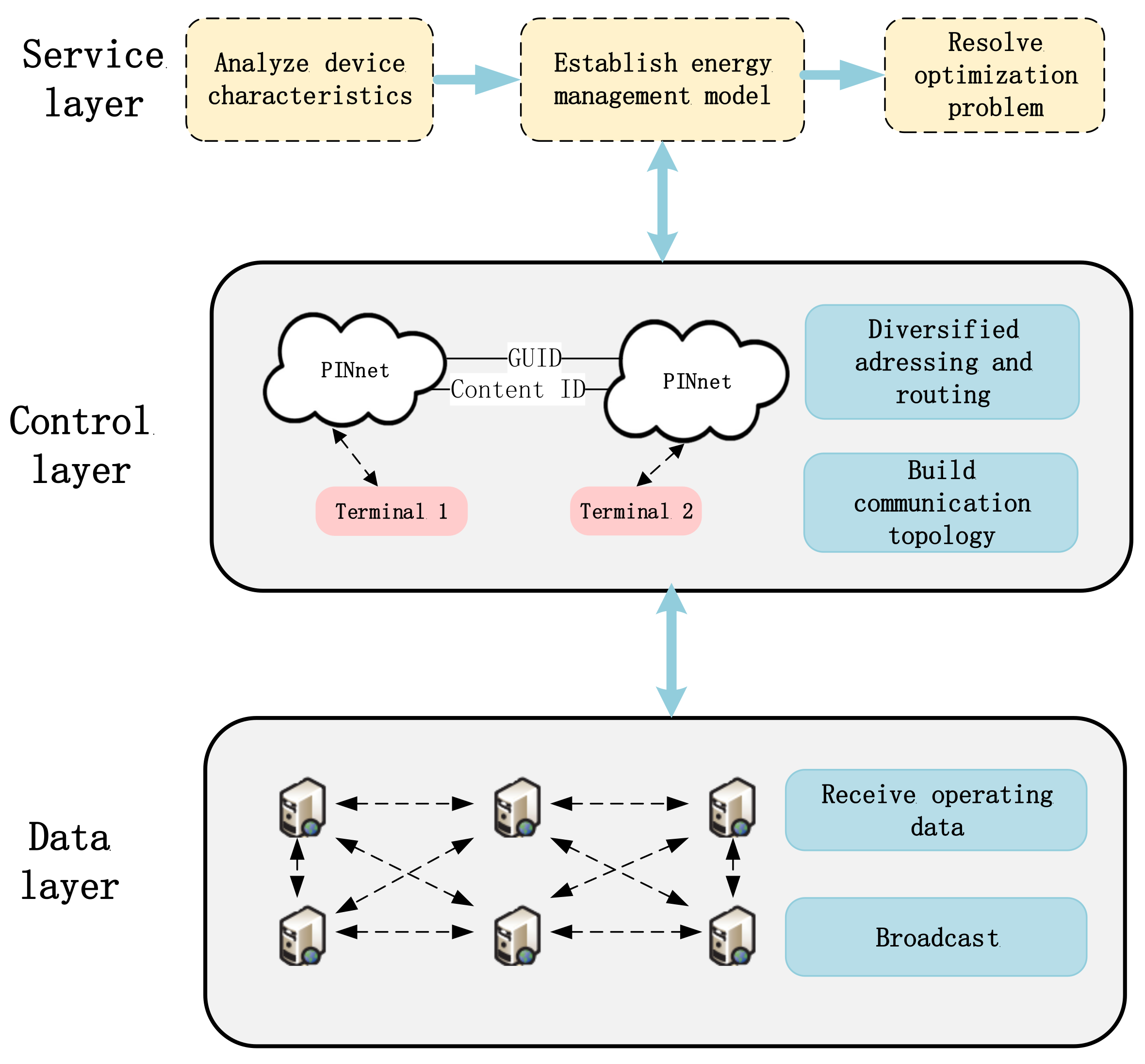
  • A seaport integrated energy system under the polymorphic network is constructed. Considering heterogeneous energy devices, a polymorphic network is adopted to ensure the information interaction between different devices and provide technical support for energy management of the seaport integrated energy system. Specifically, the polymorphic network-based seaport integrated energy system includes a data layer for data forwarding, a control layer for addressing routing, and a service layer for energy management.
  • An energy management model for the seaport integrated energy system is established by analyzing the features of different energy devices. The objective is to minimize the total operating cost, which includes the carbon emission cost, energy purchase cost, and clean energy generation cost. As the energy conversion hubs, the characteristics of CCHP and P2G are considered in the constraints to ensure reliable operation. Mixed integer linear programming is employed to solve the optimization problem.

2. Seaport Integrated Energy System under Polymorphic Network
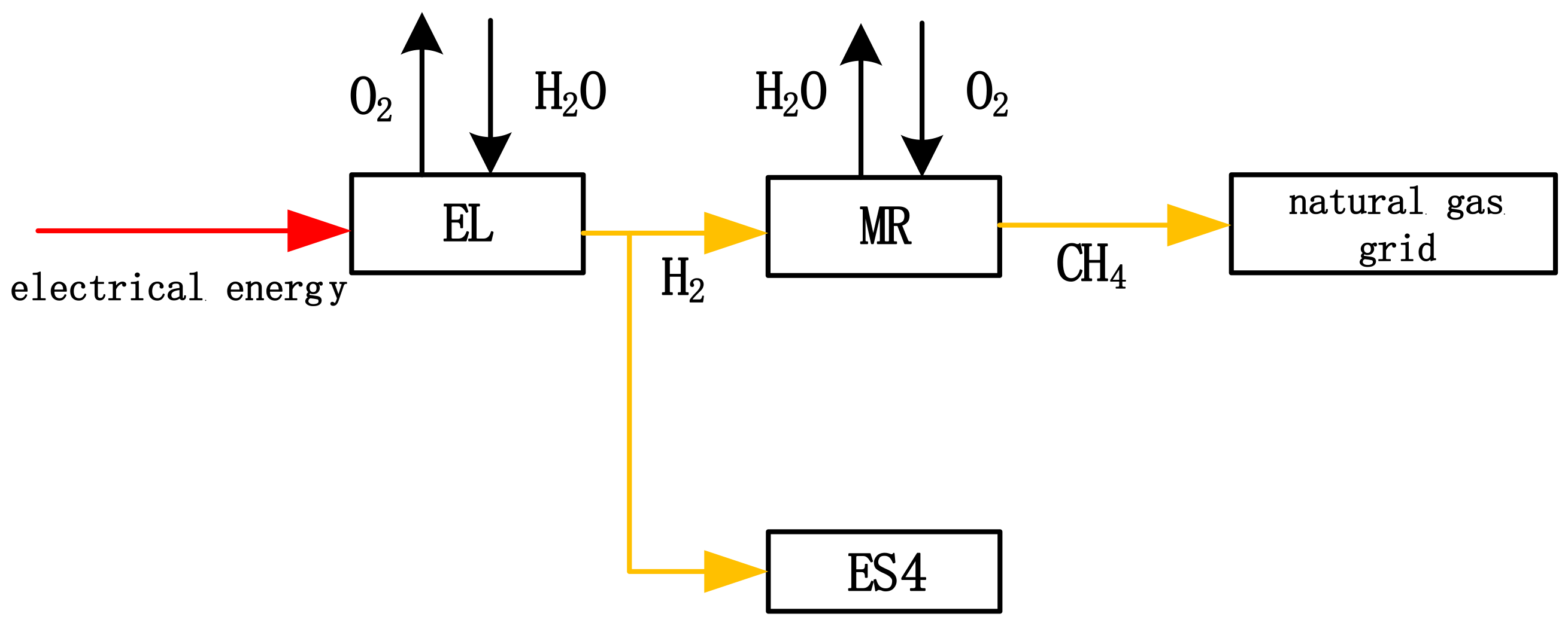
In this section, the seaport integrated energy system under the polymorphic network is constructed, consisting of the energy supply devices, energy conversion devices, loads, and energy storage devices, as shown in Figure 1. CCHP and P2G, as the seaport integrated energy conversion hubs, couple multiple energy flows, and their mathematical models are detailed in Section 2.1 and Section 2.2. Under the polymorphic network, the seaport integrated energy system breaks the information barrier and realizes information exchange between different devices.

2.1. Power to Gas

As a green, efficient, and clean energy, hydrogen plays an essential role in the seaport integrated energy system [35]. The P2G technology is able to generate synthetic natural gas from clean energy for electricity, decreasing the curtailment of clean energy. It includes two processes: electrolysis of hydrogen and hydrogen methanation, as shown in Figure 2.
In the first step of P2G, gaseous hydrogen is formed by electrolysis. Part of the hydrogen is supplied to the MR for producing natural gas, which is provided to the GT and CCHP system. Part of the hydrogen is delivered to the HFC, which is converted into electricity and heating, and the remainder is stored directly through the hydrogen storage unit. Hydrogen is more efficient than natural gas, does not emit carbon emissions, and contributes to clean energy utilization.

2.1.1. Electrolyzer

The energy conversion relationship of the EL is shown in Equation (1):
M E L , H 2 ( t ) = η E L P e , E L ( t ) P e , E L min P e , E L ( t ) P e , E L max Δ P e , E L min P e , E L ( t + 1 ) P e , P 2 H ( t ) Δ P e , E L max
where P e , E L ( t ) and M E L , H 2 ( t ) are the electricity input and hydrogen output of EL in the t period, respectively. The energy conversion efficiency of the EL is η EL , and it is closely related with the working temperature and current output. The upper and lower bounds of the electrical energy input to the EL are P e , E L max and P e , E L min , respectively. EL’s upper and lower climbing bounds are Δ P e , E L max and Δ P e , E L min , respectively.

2.1.2. Methane Reactor

The energy conversion relationship for MR is shown in Equation (2):
Q MR , g ( t ) = η MR M H 2 , MR ( t ) M H 2 , MR min P H 2 , MR ( t ) M H 2 , MR max Δ M H 2 , MR min M H 2 , MR ( t + 1 ) M H 2 , MR ( t ) Δ M H 2 , MR max
where Q MR , g ( t ) and M H 2 , MR ( t ) are the natural gas output and hydrogen input and of MR in the t period, respectively. The energy conversion efficiency of the MR is η MR . The upper and lower bounds of hydrogen energy input to the MR are M H 2 , MR max and M H 2 , MR min , respectively. MR’s upper and lower climbing bounds are Δ M H 2 , MR max and Δ M H 2 , MR min , respectively.

2.1.3. Hydrogen Fuel Cell

The energy conversion relationship of the HFC is shown in Equation (3):
P HFC , e ( t ) = η HFC e M H 2 , HFC ( t ) H HFC , h ( t ) = η HFC h M H 2 , HFC ( t ) M H 2 , HFC min M H 2 , HFC ( t ) M H 2 , HFC max Δ M H 2 , HFC min M H 2 , HFC ( t + 1 ) M H 2 , HFC ( t ) Δ M H 2 , HFC max κ HFC min H HFC , h ( t ) / P HFC , e ( t ) κ HFC max
where M H 2 , HFC ( t ) , P HFC , e ( t ) and H HFC , h ( t ) are the hydrogen input, electricity output and heating output of HFC in the t period, respectively. η HFC e , η HFC h are the conversion efficiencies of HFC into electricity and heating, respectively. The upper and lower bounds of the hydrogen energy input to the HFC are M H 2 , HFC max and M H 2 , HFC min , respectively. HFC’s upper and lower climbing bounds are Δ M H 2 , HFC max and Δ M H 2 , HFC min , respectively. The upper and lower bounds of the HFC’s thermoelectric ratio are κ HFC max , and κ HFC min , respectively.

2.2. Combined Cooling Heating and Power

The user side of CCHP utilizes gas as fuel. CCHP produces electricity from GT, and the waste heat generated during the generation process is considered for cooling and heating. Nowadays, CCHP has been widely utilized and can be applied to seaport devices such as liquefied natural gas (LNG) [36], which can be described as Equation (4):
P CCHP , e ( t ) = η CCHP e Q g , CCHP ( t ) H CCHP , h ( t ) = η CCHP h Q g , CCHP ( t ) L CCHP , L ( t ) = η CCHP L Q g , CHPP ( t ) Q g , CCHP min Q g , CCHP ( t ) Q g , CCHP max Δ Q g , CCHP min Q g , CCHP ( t + 1 ) Q g , CCHP ( t ) Δ Q g , CCHP max κ CCHP min H CCHP , h ( t ) / P CCHP , e ( t ) κ CCHP max
where Q g , CCHP ( t ) is the natural gas input to CCHP in t period. P CCHP , e ( t ) , H CCHP , h ( t ) , and L CCHP , L ( t ) are the electricity, heating and cooling output by CCHP in t period, respectively. η CCHP e , η CCHP h , and η CCHP L are the conversion efficiencies of CCHP into electricity, heating and cooling, respectively. The upper and lower bounds for natural gas input to CCHP are Q g , CCHP max and Q g , CCHP min , respectively. Δ Q g , CCHP max and Δ Q g , CCHP min can be defined as the upper and lower bounds of CCHP climbing, respectively; κ CCHP max and κ CCHP min can be defined as the upper and lower bounds of the thermoelectric ratio of CCHP, respectively.

2.3. Polymorphic Network-Based Seaport Integrated Energy System

As can be seen in Figure 1, the seaport integrated energy system contains heterogeneous energy devices and is different from the traditional energy system with a single energy flow. Energy devices are commonly produced by various manufacturers with different protocols. The typical protocol in the traditional communication network is the internet protocol version 6(IPV6) [37], which has poor security and can not realize reliable information transmission between heterogeneous energy devices. To break the drawbacks of the traditional communication network, we build a polymorphic network-based seaport integrated energy system. Polymorphic network supports polymorphic modalities based on content, identity, and other identifiers, containing the polymorphic presentation of functions.

2.3.1. MobilityFirst

Considering different load demands, mobile energy devices are needed for energy management in specific circumstances of the seaport integrated energy system. Mobile energy devices such as ships need to be identified in energy management, so the communication network should be able to realize the mobility connection between different devices. Meanwhile, the seaport integrated energy system’s communication network is open and is vulnerable to attack, so the security of its communication network should be considered. Based on the above analysis, the seaport integrated energy system should choose a communication network with mobility and security. MobilityFirst (MF) is a network architecture that separates location identification and identity identification. Its unique mobility and security can solve the seaport integrated energy system’s communication issues. [38].
The MF network ensures mobility communication between different devices of the seaport integrated energy system [39]. Each device is assigned a globally unique identity (GUID) in the seaport integrated energy system. Meanwhile, these devices are mapped to the communication networks’ corresponding network addresses (NAs), which determine their location quickly. The GUID will not change under any circumstances, but the NA will change when the device moves. The dynamic mapping between GUID and NA realizes seamless host and network mobility. In addition, the mapping relationship between GUID and NA is maintained by the global name resolution service (GNRS). When a device needs to get the energy supply information of other devices, GNRS will provide mobility support by querying the mapping table between GUID and NA. Therefore, in the seaport integrated energy system, MF realizes the information linkage between various types of devices.
On the other hand, the MF network secures data transmission between various devices in the seaport integrated energy system. When the seaport integrated energy system’s communication network depends on the traditional IP network, the routing failure of a single device may lead to the paralysis of the whole network and cause severe economic loss. However, when the communication network of the seaport integrated energy system relies on the MF network, a few attacked nodes will not cause a disproportionate impact on the overall performance. It will realize safe and reliable information transmission between devices under different circumstances. In MF, generalized storage-aware routing (GSTAR) is proposed to cope with the intermittent connection between nodes and networks during information transmission. When a device in the seaport integrated energy system has a location movement that leads to an interruption of connection with the main network, the router will temporarily store the packets sent by the device. If the device moves to the coverage of the wide area network (WAN) access point, the router will reacquire the device’s network address. The router continues to follow the routing table and sends the packets to the destination node. Therefore, the MF network provides data transmission integrity and meets data transmission security requirements.
In summary, MF breaks the information barriers brought by traditional networks and establishes a new open and flexible network architecture. To realize the comprehensive energy management of the seaport integrated energy system, the polymorphic network is applied to provide personalized and efficient services for the seaport.

2.3.2. Structure of Polymorphic Network-Based Seaport Integrated Energy System

Various energy devices by different manufacturers are included in the seaport integrated energy system. Under different environments, different communication modalities, including the mentioned MF, need to be used. Therefore, a general structure of polymorphic network-based seaport integrated energy system is established, including the service layer, control layer, and data layer, as shown in Figure 3. Specifically, the functions of each layer are as follows. The data layer can receive operating data and broadcast it between different devices. The control layer meets diverse addressing routing modes and constructs communication topology. The service layer constructs the energy management model of the seaport integrated energy system and solves the optimization problem by analyzing various device characteristics. In this structure, cooperative optimization and energy management among heterogeneous devices can be realized in the seaport integrated energy system.

3. Energy Management Model for Seaport Integrated Energy System

Based on the seaport integrated energy system established, the energy management model for the system is constructed by the analysis of the device characteristics.

3.1. Objective Function

The optimization objective is to minimize the operation cost of the seaport integrated energy system. The objective function can be described as Equation (5):
F = min C buy + C CO 2 + C WTPV
where C buy , C c o 2 , and C WTPV are the energy purchase cost, the carbon emissions cost, and the clean energy cost, respectively.

3.1.1. Energy Purchase Cost C buy

Electricity and gas purchases are included in the cost of energy purchase, as shown in Equation (6):
C buy = t = 1 T C e P e , buy ( t ) + t = 1 T C g Q g , buy ( t )
where T is a scheduling period, usually 24 h. P e , buy ( t ) , Q g , buy ( t ) are the purchased electricity and gas volume in t period, respectively. C e is the electricity price in t period, and C g is the gas price.

3.1.2. Carbon Emissions Cost C c o 2

The carbon emissions cost includes the cost of carbon emissions from electricity and natural gas, as shown in Equation (7):
C c o 2 = c c o 2 t = 1 T α c o 2 P e , buy ( t ) + β c o 2 Q g , buy ( t )
where c c o 2 is the unit carbon price, α c o 2 and β c o 2 are the carbon dioxide emission factor of power grid and natural gas, respectively.

3.1.3. Clean Energy Cost C WTPV

The cost of clean energy is shown in Equation (8):
C WTPV = c WT t = 1 T P WT 4 + c PV t = 1 T P PV 4
where c WT and c PV are the unit per average power generation cost of WT [40] and PV [41], respectively. P PV , P WT are the power output of PV and WT in t period, respectively.

3.2. Constraints

In this section, the constraints of the seaport integrated energy system are described in detail. The HFC, EL, MR and CCHP operating constraints are described as Equations (1)–(4), respectively.

3.2.1. Clean Energy Constraints

WT and PV have flexible and stable power generation performance and are widely used in integrated energy systems [42]. Equations (9) and (10) are the constraints of WT and PV, respectively.
0 P WT ( t ) P WT max
0 P PV ( t ) P PV max
However, the WT output is affected by the wind speed and exists an output upper bound P WT max . Due to the influence of light intensity and panel area, PV also exists an upper bound of PV output P PV max .

3.2.2. GT Constraint

The GT is connected to the natural gas network with excellent performance, as shown in Equation (11):
H GT , h ( t ) = η GT , h Q g , GT ( t ) P GT , e ( t ) = η GT , e Q g , GT ( t ) Q g , GT min Q g , GT ( t ) Q g , GT max Δ Q g , GT min Q g , GT ( t + 1 ) Q g , GT ( t ) Δ Q g , GT max
where η GT , h and η GT , e are the heat energy and electricity energy conversion efficiencies of the GT, respectively, and have a certain relationship with the compressor inlet guide vane angle and the steam turbine extraction ratio [43]. The electrical input to the GT in t period is denoted by Q g , GT ( t ) . H GT , h ( t ) and P GT , e ( t ) are the heat and electricity outputs of GT in the t period, respectively. The GT input’s upper and lower bounds are Q g , GT max and Q g , GT min , respectively.

3.2.3. Energy Storage Devices Constraints

An electricity storage device is considered in the seaport integrated energy system [44], and the relevant constraint is shown in Equation (12):
0 P ES , 1 cha ( t ) B ES , 1 cha ( t ) P ES , 1 max 0 P ES , 1 dis ( t ) B ES , 1 dis ( t ) P ES , 1 max P ES , 1 ( t ) = P ES , 1 cha ( t ) η ES , 1 cha P ES , 1 dis ( t ) / η ES , 1 dis S 1 ( t ) = S 1 ( t 1 ) + P ES , 1 ( t ) / P ES , 1 cap S 1 ( 1 ) = S 1 ( T ) B ES , 1 cha ( t ) + B ES , 1 dis ( t ) = 1 S 1 min S 1 ( t ) S 1 max
where P ES , 1 cha ( t ) , P ES , 1 dis ( t ) , and P ES , 1 max are the charging power, discharging power and upper bound of the seaport electricity storage device in t period, respectively. In the t period, B ES , 1 cha ( t ) and B ES , 1 dis ( t ) are defined as the seaport energy storage device’s charging and discharging state parameters, respectively. B ES , 1 cha ( t ) = 1 , B ES , 1 dis ( t ) = 0 means the charging state. B ES , 1 cha ( t ) = 0 , B ES , 1 dis ( t ) = 1 means the discharging state. P ES , 1 ( t ) , P ES , 1 cap are the power input and rated capacity of the seaport electricity storage device in t period, respectively. The charging and discharging efficiencies of the seaport electricity storage device are represented by η ES , 1 cha and η ES , 1 dis , respectively. The capacity of the seaport electricity storage device is defined by S 1 ( t ) , and its upper and lower bounds are defined by S 1 max and S 1 min , respectively.
The seaport integrated energy system takes into account heat and cold storage devices in order to accomplish the clean energy utilization of CCHP. The model for the heat storage device is shown in Equation (13):
0 H ES , 2 cha ( t ) B ES , 2 cha ( t ) H ES , 2 max 0 H ES , 2 dis ( t ) B ES , 2 dis ( t ) H ES , 2 max H ES , 2 ( t ) = H ES , 2 cha ( t ) η ES , 2 cha H ES , 2 dis ( t ) / η ES , 2 dis S 2 ( t ) = S 2 ( t 1 ) + H ES , 2 ( t ) / H ES , 2 cap S 2 ( 1 ) = S 2 ( T ) B ES , 2 cha ( t ) + B ES , 2 dis ( t ) = 1 S 2 min S 2 ( t ) S 2 max
where the upper bound of charging or discharging is defined by H ES , 2 max , and its charging and discharging thermal power are defined by H ES , 2 cha ( t ) and H ES , 2 dis ( t ) , respectively. In the t period, B ES , 2 cha ( t ) and B ES , 2 dis ( t ) are defined as the charging and discharging state parameters of the seaport heat storage device in t period, respectively. B ES , 2 cha ( t ) = 1 , B ES , 2 dis ( t ) = 0 means the charging state. B ES , 2 cha ( t ) = 0 , B ES , 2 dis ( t ) = 1 means the discharging state. H ES , 2 ( t ) and H ES , 2 cap are the power input and rated capacity of the seaport heat storage device in t period, respectively. The charging and discharging efficiencies of the seaport heat storage device are represented by η ES , 2 cha and η ES , 2 dis , respectively. The capacity of the seaport heat storage device is defined by S 2 ( t ) , and its upper and lower bounds are defined by S 2 max and S 2 min , respectively.
Equation (14) shows the model of the seaport cold storage device:
0 L ES , 3 cha ( t ) B ES , 3 cha ( t ) L ES , 3 max 0 L ES , 3 dis ( t ) B ES , 3 dis ( t ) L ES , 3 max L ES , 3 ( t ) = L ES , 3 cha ( t ) η ES , 3 cha L ES , 3 dis ( t ) / η ES , 3 dis S 3 ( t ) = S 3 ( t 1 ) + L ES , 3 ( t ) / L ES , 3 cap S 3 ( 1 ) = S 3 ( T ) B ES , 3 cha ( t ) + B ES , 3 dis ( t ) = 1 S 3 min S 3 ( t ) S 2 max
where the upper bound of charging or discharging is defined by L ES , 3 max , and its charging and discharging cold power are defined by L ES , 3 cha ( t ) and L ES , 3 dis ( t ) , respectively. In the t period, B ES , 3 cha ( t ) and B ES , 3 dis ( t ) are defined as the charging and discharging state parameters of the seaport cold storage device in t period, respectively. B ES , 3 cha ( t ) = 1 , B ES , 3 dis ( t ) = 0 means the charging state. B ES , 3 cha ( t ) = 0 , B ES , 3 dis ( t ) = 1 means the discharging state. L ES , 3 ( t ) and L ES , 3 cap are the power input and rated capacity of the seaport cold storage device in t period, respectively. The charging and discharging efficiencies of the seaport cold storage device are represented by η ES , 3 cha and η ES , 3 dis , respectively. The capacity of the seaport cold storage device is defined by S 3 ( t ) , and its upper and lower bounds are defined by S 3 max and S 3 min , respectively.
The seaport hydrogen storage device can effectively utilize hydrogen energy from HFC and ensures a stable shift of hydrogen, as shown in Equation (15):
0 M ES , 4 cha ( t ) B ES , 4 cha ( t ) M ES , 4 max 0 M ES , 4 dis ( t ) B ES , 4 dis ( t ) M ES , 4 max M ES , 4 ( t ) = M ES , 4 cha ( t ) η ES , 4 cha M ES , 4 dis ( t ) / η ES , 4 dis S 4 ( t ) = S 4 ( t 1 ) + M ES , 4 ( t ) / M ES , 4 cap S 4 ( 1 ) = S 4 ( T ) B ES , 4 cha ( t ) + B ES , 4 dis ( t ) = 1 S 4 min S 4 ( t ) S 4 max
where the upper bound of charging or discharging is defined by M ES , 4 max , and its charging and discharging hydrogen power are defined by M ES , 4 cha ( t ) and M ES , 4 dis ( t ) , respectively. In the t period, B ES , 4 cha ( t ) and B ES , 4 dis ( t ) are defined as the charging and discharging state parameters of the seaport hydrogen storage device in t period, respectively. B ES , 4 cha ( t ) = 1 , B ES , 4 dis ( t ) = 0 means the charging state. B ES , 4 cha ( t ) = 0 , B ES , 4 dis ( t ) = 1 means the discharging state. M ES , 4 ( t ) and M ES , 4 cap are the power input and rated capacity the seaport hydrogen storage device in t period, respectively. The charging and discharging efficiencies of the seaport hydrogen storage device are represented by η ES , 4 cha and η ES , 4 dis , respectively. The capacity of the seaport hydrogen storage device is defined by S 4 ( t ) , and its upper and lower bounds are defined by S 4 max and S 4 min , respectively.

3.2.4. Electricity Balance Constraint

The electricity balance constraint is shown in Equation (16):
P e , buy ( t ) + P PV ( t ) + P WT ( t ) + P CCHP , e ( t ) + P HFC , e ( t ) + P GT , e ( t ) = P Load E ( t ) + P e , EL ( t ) + P ES , 1 ( t ) 0 P e , buy ( t ) P e , buy max
where P e , buy max and P Load E ( t ) are the upper bound of purchasing electricity and the electricity load in t period, respectively.

3.2.5. Natural Gas Balance Constraint

Equation (17) shows the constraint of the natural gas balance:
Q g , buy ( t ) + Q MR , g ( t ) = Q g , CCHP ( t ) + Q g , GT ( t ) 0 Q g , buy ( t ) Q g , buy max
where Q g , buy max is the upper bound of purchasing natural gas.

3.2.6. Heat Balance Constraint

The heat balance constraint is shown in Equation (18):
H HFC , h ( t ) + H CCHP , h ( t ) + H GT , h ( t ) = H Load H ( t ) + H ES , 2 ( t )
where H Load H ( t ) denotes the heat load during the t period.

3.2.7. Cold Balance Constraint

The cold balance constraint is shown in Equation (19):
L CCHP , L ( t ) = L Load L ( t ) + L ES , 3 ( t )
where L Load L ( t ) is the cold load in t period.

3.2.8. Hydrogen Balance Constraint

The hydrogen balance constraint is shown in Equation (20):
M EL , H 2 ( t ) = M H 2 , MR ( t ) + M H 2 , HFC ( t ) + M ES , 4 ( t )

4. Simulation

To validate the dispatch optimization strategy given in this article, the strategy is employed to optimize the operating of the seaport integrated energy system. The dispatch period is 24 h, and the unit dispatch period is 1 h. A day’s forecasted WT and PV output are given in Table 1. Table 2 and Table 3 describe the time-of-use electricity prices and operating parameters, respectively. The price of natural gas is 0.35 yuan/(kW·h). The unit carbon emission cost is 0.17 yuan/(kW·h), the per unit average power generation cost of WT and PV are 0.43 yuan/(kW·h) and 0.653 yuan/(kW·h), respectively.

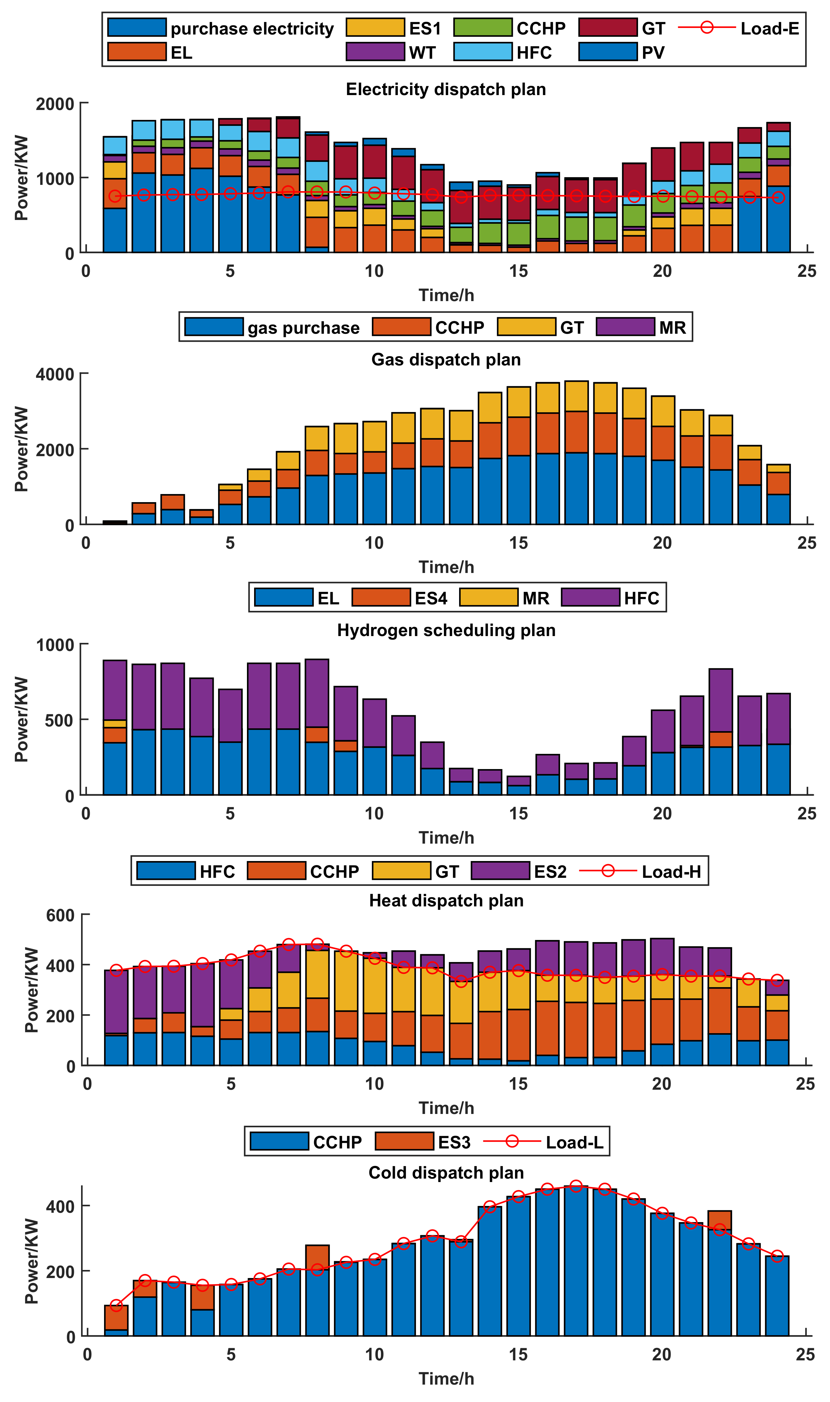
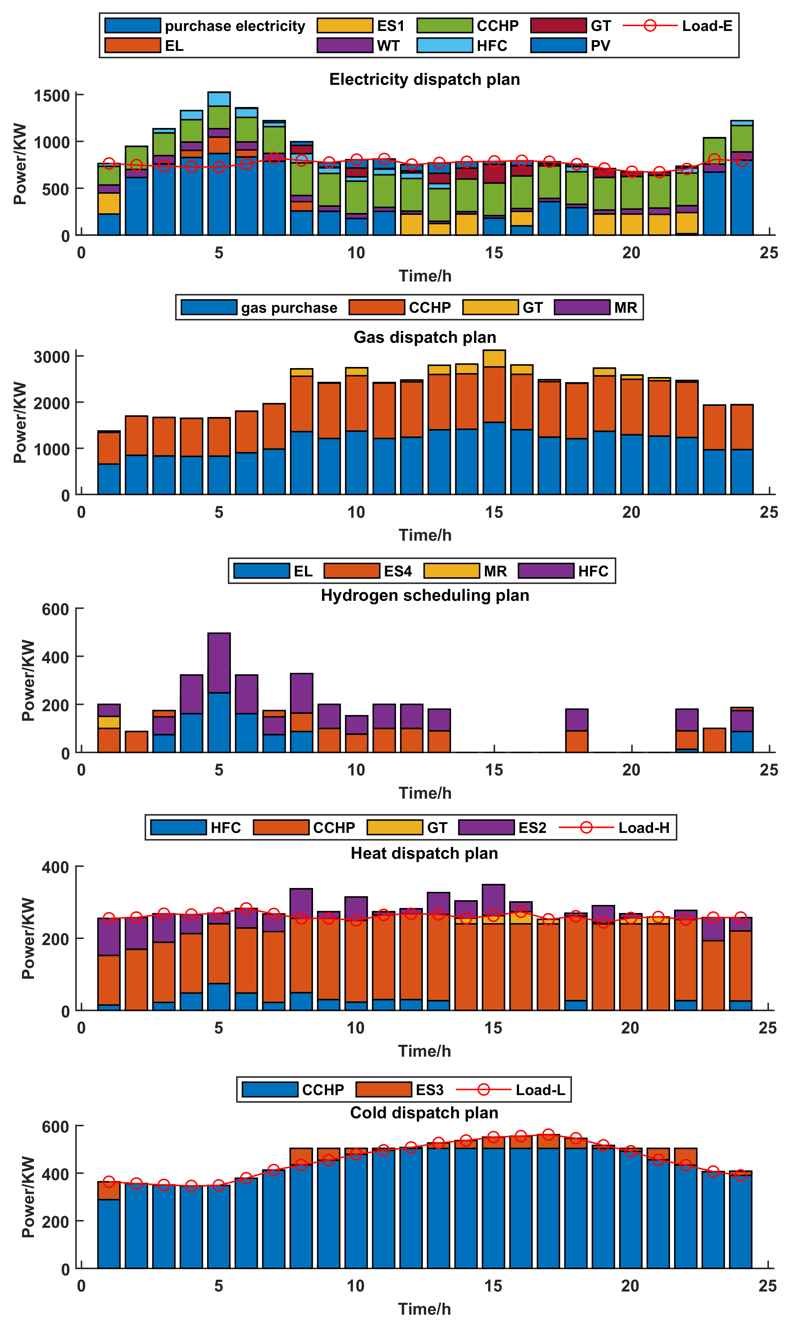
4.1. Impact of Energy Storage Devices and Clean Energy in Seaport Integrated Energy System

To validate the proposed energy management strategy for the seaport integrated energy system, a typical day is selected for dispatch, four comparison cases are established as follows, Table 4 shows the simulation results of the four compared cases.
Case 1: a seaport integrated energy system includes PV and WT but does not include energy storage devices.
Case 2: a seaport integrated energy system includes energy storage devices but does not include PV and WT.
Case 3: a seaport integrated energy system includes energy storage devices together with PV and WT.
Case 4: a seaport integrated energy system includes energy storage devices together with PV and WT but the HFC is faulty from 1:00 to 6:00.
When case 1 and case 3 are compared, it is clear that case 3 can significantly improve the utilization rate of clean energy while saving the total operating cost. Since WT and PV are not considered, the cost of WT and PV is 0 in case 1. Purchasing electricity and gas from the power grid and gas grid to meet the load demand, resulting in a substantial increase of purchasing energy costs from 11,169 yuan to 11,885 yuan. Since WT and PV are affected by various factors, such as the environment, it has an upper output bound. It is necessary to combine other devices to supply demands. The total operating cost dropped from 21,745 to 22,882 yuan.
Comparing case 2 and case 3, case 2’s ineffective regulation of the seaport integrated energy system is caused by the absence of energy storage devices. The cost of purchasing electricity and the cost of carbon emissions are both significantly increased. When there is a surplus of energy, energy storage devices can temporarily store it and realize a timely shift of energy. With the energy storage devices being adapted for the seaport integrated energy system, the cost of purchasing electricity has reduced from 11,847 to 11,169 yuan. The decrease in energy purchase cost leads to the decrease in the carbon emissions cost from 10,816 yuan to 10,311 yuan. The total operating cost of the seaport integrated energy system reduces from 22,928 yuan to 21,745 yuan with the participation of energy storage devices, improving the efficiency of system operation.
Comparing case 3 and case 4, we find that there is no impact on the costs of the seaport integrated energy system when the HFC is cut out, demonstrating the effectiveness of the proposed energy management strategy.
Therefore, case 3 is the most economical and stable solution for the seaport integrated energy system.

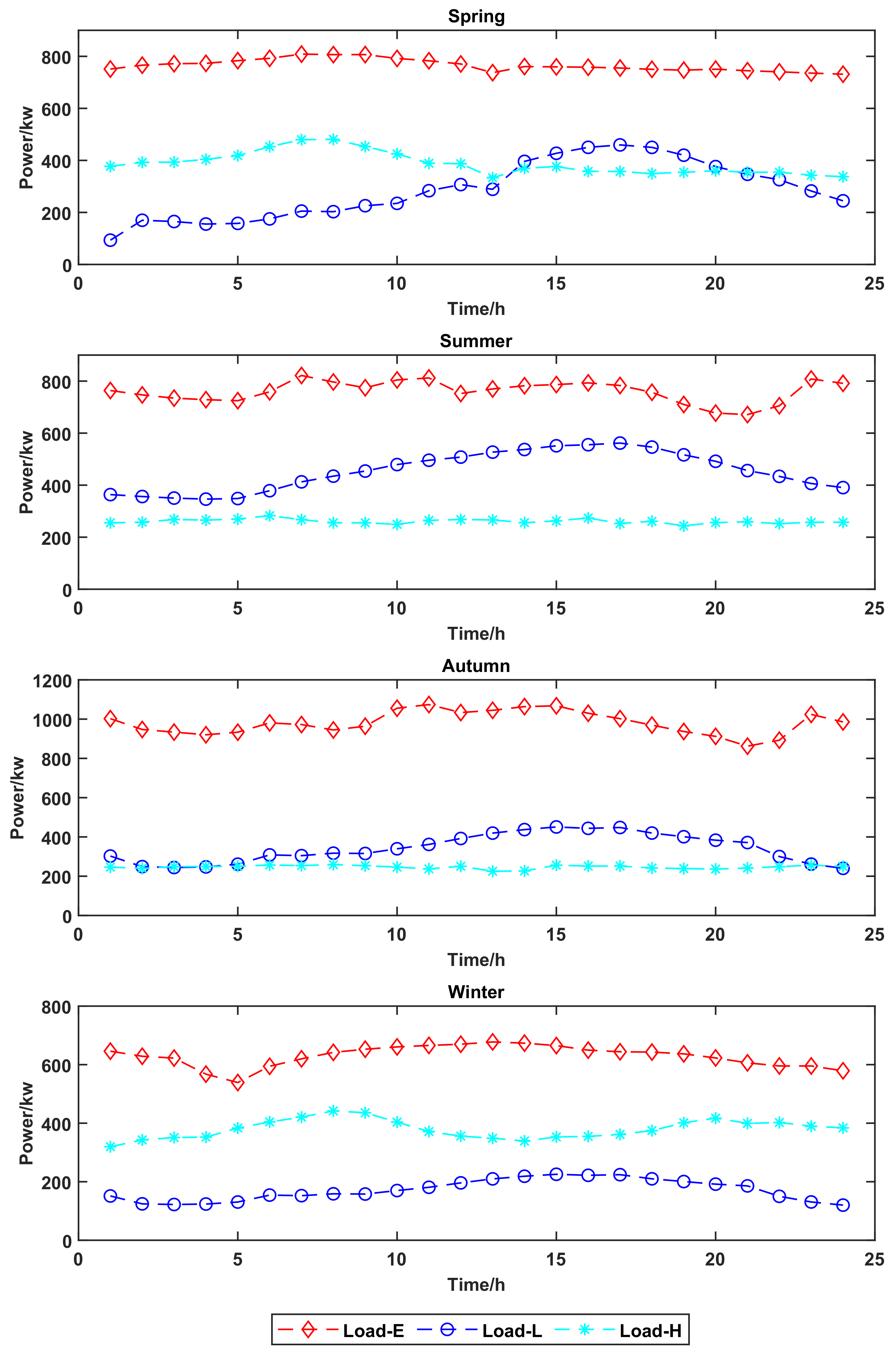
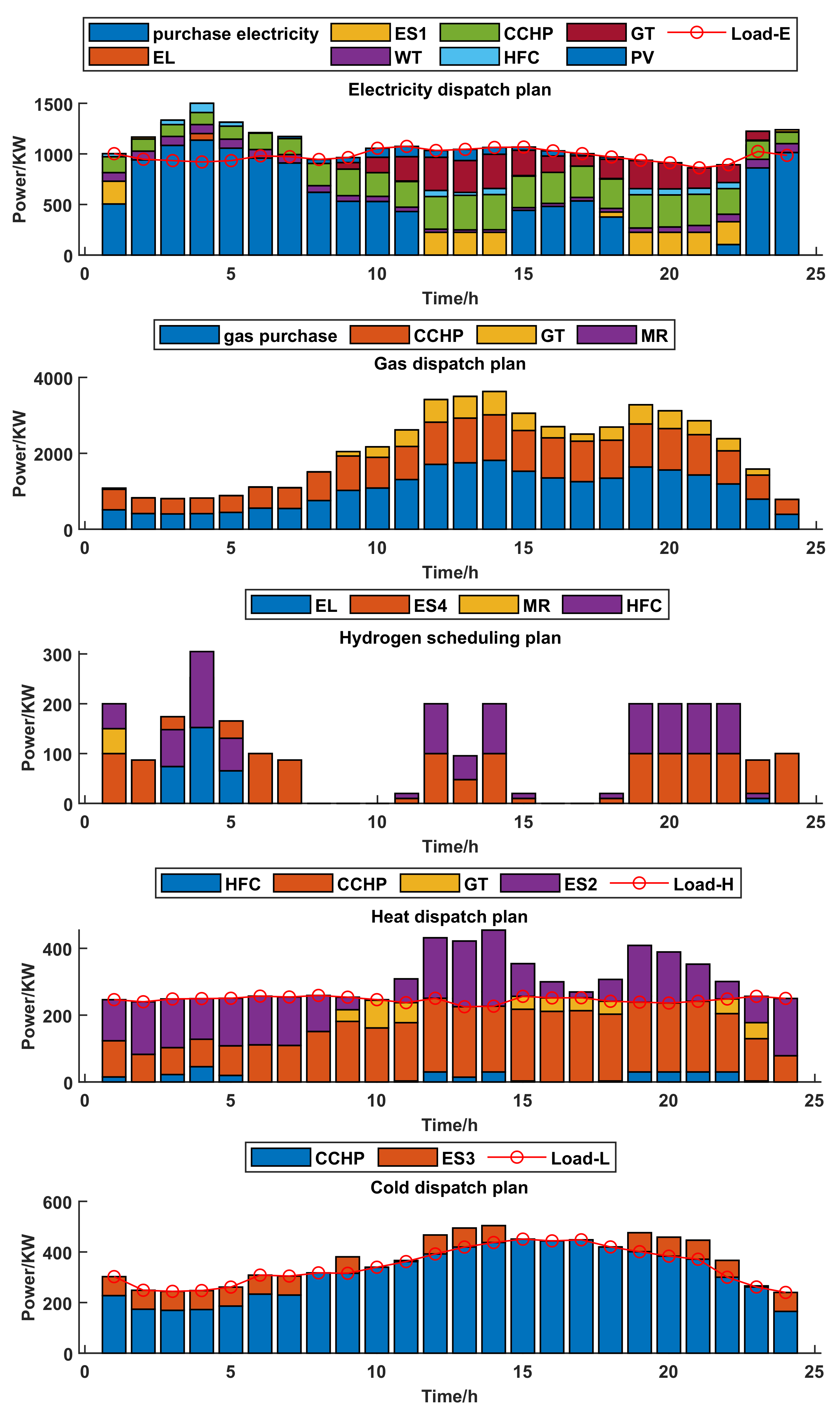
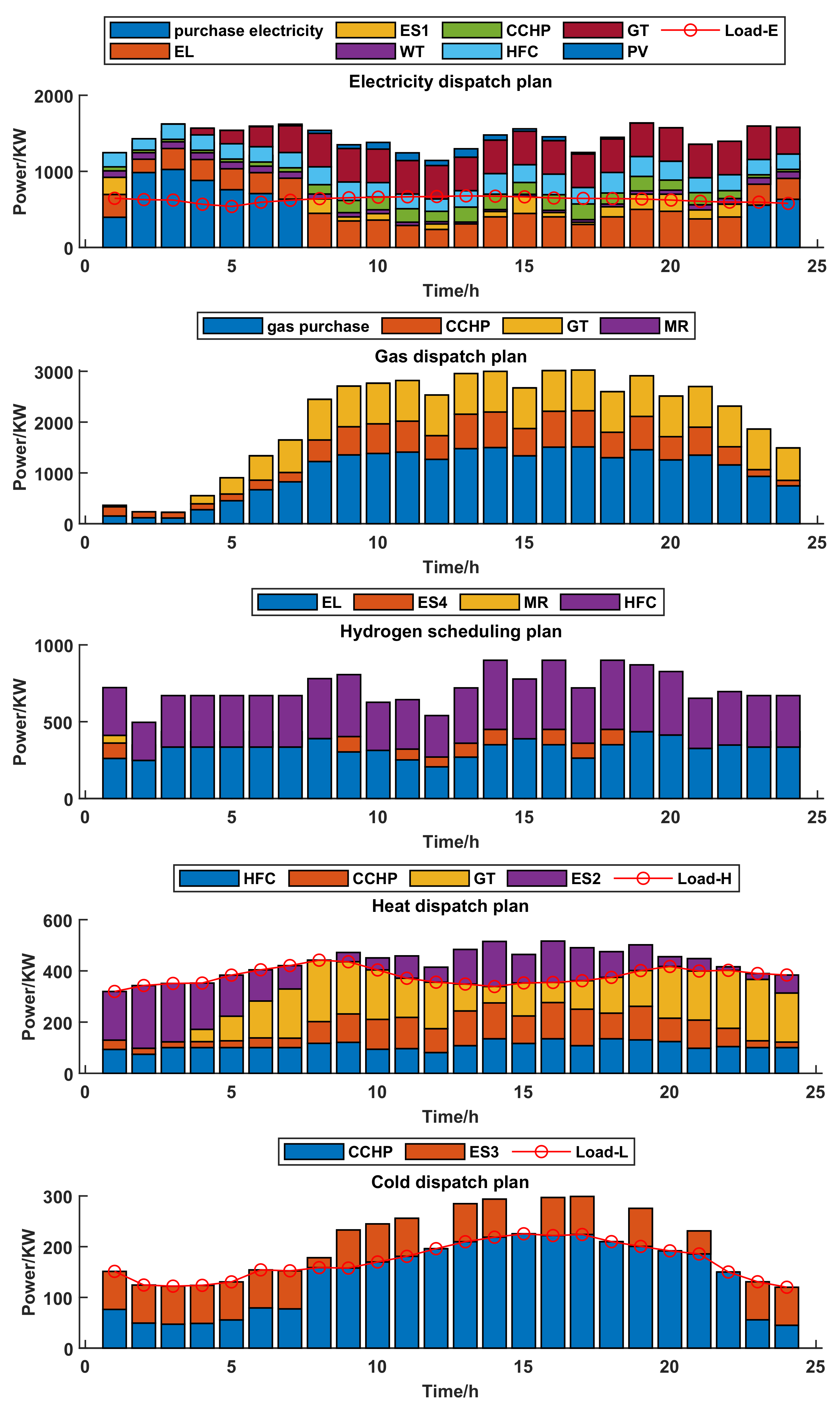
4.2. Impact of Sensonal Changes in Seaport Integrated Energy System

Considering the impact of seasonal changes on the loads, we applied the proposed energy management strategy of the integrated port energy management system on four typical days with different cold, heat and electricity loads, and the corresponding results are shown in the Figure 4.
As illustrated in Figure 5, in spring, the electrical load is high because of the large amount of electrical devices in the seaport. In the electricity dispatch plan, from 1:00 to 7:00, the price of electricity is low so that the purchased electricity cost increases significantly, the storage device is charged, and the demand can be met by electrical production from HFC. From 8:00 to 22:00, the price of electricity is high, so the storage device is discharged. CCHP and GT are the main generating equipment, so the cost of purchased gas increases as well. WT and PV are used to support other devices in the electricity dispatch plan of the seaport integrated energy system. Hydrogen is considered an intermediate conversion energy, and its dispatch follows the other energy flows.
As shown in Figure 6, in summer, high temperatures result in a higher cold load on the typical summer day than on others. Due to the excellent cold efficiency of the CCHP, the cold load is supplied entirely by the CCHP. From 8:00 to 22:00, there is a plentiful supply for cold load, which means that the CCHP requires a substantial amount of natural gas. The cost of purchasing gas rises correspondingly. Time-shifting energy is produced from the cold storage device only in some moments. In the electricity dispatch plan, the CCHP is the primary power generator, as well as, the storage device, HFC, WT, and PV function as auxiliary power generators. Since the heat load consumes less energy than the cold and electric loads, the GT acts as the primary generator in the heat dispatch plan. The seaport integrated energy system does not dispatch hydrogen when other energy flows can ensure a balance between supply and demand, and the hydrogen energy flow is not involved directly in the dispatch of the system.
As illustrated in Figure 7, in autumn, unlike spring, the seaport integrated energy system has greater electrical demands and fewer cold, heat requirements, resulting in heat and cold redundancy and hence more appropriate heat and cold storage. Because of the excellent electrical load on the system, the storage device is discharged more frequently, and the CCHP, GT, and HFC don’t have quite the same outputs in the electricity dispatch plan as in the spring, while the other devices have a similar effect. After 9:00, as the need for heat and electricity increases and the cost of electricity increases, GT requires more gas and should buy substantially more gas from the gas grid, increasing both the cost of the gas purchase and carbon emissions.
As shown in Figure 8, in winter, due to temperature variations, the electricity and cold loads of the seaport integrated energy system are not as substantial as the heat load. Consequently, HFC, CCHP, and GT collaborate to maintain a balance of supply and demand in the heat dispatch plan. Where HFC as a clean energy device always produces a balanced power output, GT and CCHP produce less heat when energy is stored, in 1:00–3:00, GT even does not produce heat, resulting in a corresponding drop in natural gas usage. At the same time, as the CCHP is used for combined cold, heat, and electricity supply, it makes a minor contribution to the electricity dispatch plan, with the GT being the main electricity generator, as well as the HFC and other devices assisting in the production of electricity.
In conclusion, the CCHP and energy storage system can flexibly adjust the output according to the different load changes in the four seasons, while the output of other devices will also be changed together with the CCHP and energy storage system. Consequently, a seaport integrated energy system with CCHP and storage system may achieve smarter and more flexible energy management during all seasons, prioritizing clean energy producing devices and significantly reducing carbon emissions and energy purchase costs.

5. Conclusions

The energy management strategy of the seaport integrated energy system under the polymorphic network has been proposed in this paper. Firstly, to break down information barriers between heterogeneous devices, a seaport integrated energy system based on the polymorphic network has been constructed with a diversity of energy devices, including the service layer, control layer, and data layer. Moreover, considering its security and mobility demands, MF can be implemented as the communication modality selected from a variety of modalities. Secondly, by analyzing the characteristics of various loads and the energy conversion hub including P2G and CCHP, the energy management model of the seaport integrated energy system has been established, and has been used to a seaport integrated energy system including clean energy and energy storage device. By comparing four different cases, we have found that the simulation shows a reduction in the cost of energy purchase and carbon emissions when applying our strategy to various device types and device failures. Moreover, we consider the application of the proposed energy management strategy under seasonal variations and also obtain the optimal solution for the energy management problem for the seaport integrated energy system. It is found that the output of each device has changed with the output of the CCHP and the energy storage system under different seasonal conditions. This has proven the effectiveness of the proposed management strategy. In the future, we will focus on applying the energy management strategy proposed for the seaport integrated energy system in the maritime field and construct an intelligent seaport.

Author Contributions

Conceptualization, F.T., Q.Z., T.Z., J.Z. and Y.T.; methodology, F.T. and Q.Z.; software, Q.Z.; validation, F.T. and Q.Z.; formal analysis, F.T., Q.Z. and T.Z.; resources, F.T., Q.Z. and T.Z.; data curation, J.Z., Q.F. and Y.T.; writing—original draft preparation, Y.T; writing—review and editing, Q.Z. and F.T.; supervision, F.T., T.Z. and J.Z.; project administration, F.T., T.Z. and Y.T.; funding acquisition, F.T., T.Z., J.Z. and Y.T. All authors have read and agreed to the published version of the manuscript.

Funding

This research was funded by the National Key R&D Program of China (2019YFB1802501); the Key Research Project of Zhejiang Lab (2021LE0AC02); the National Natural Science Foundation of China (under grant nos. 52201407, 62203403, 51939001, 61803064); the Science and Technology Innovation Funds of Dalian (under grant no. 2018J11CY022); the Liaoning Revitalization Talents Program (under grant nos. XLYC1908018 and XLYC1807046); the Natural Science Foundation of Liaoning (2019-ZD-0151, 20170540098); the Fundamental Research Funds for the Central Universities (under grant nos. 3132019345, 3132020103, and 3132020125).

Institutional Review Board Statement

Not applicable.

Informed Consent Statement

Not applicable.

Data Availability Statement

Not applicable.

Acknowledgments

Thanks to the hard-working editors and valuable comments from reviewers.

Conflicts of Interest

The authors declare no conflict of interest.

Abbreviations

The acronyms in the paper and their corresponding meanings are as follows:
AcronymExplanation
P2Gpower to gas
CCHPcombined cooling heating and power
IMOInternational Maritime Organization
CO2carbon dioxide
GTgas turbine
WTWind turbine
PVphotovoltaic
ELelectrolyzer
MRmethane reactor
IPV6internet protocol version 6
MFMobilityFirst
GUIDglobally unique identity
NAsnetwork addresses
GNRSglobal name resolution service
GSTARgeneralized storage-aware routing
WANwide area network
Load-Eelectricity Load
Load-Hheat load
Load-Lcold load
ES1electricity energy storage device
ES2heat energy storage device
ES3cold energy storage device
ES4hydrogen energy storage device

References

  1. Gan, M.; Li, D.; Wang, J.; Zhang, J.; Huang, Q. A Comparative Analysis of the Competition Strategy of Seaports under Carbon Emission Constraints. J. Clean. Prod. 2021, 310, 127488. [Google Scholar] [CrossRef]
  2. Fan, H.; Yu, J.; Liu, X. Tramp Ship Routing and Scheduling with Speed Optimization Considering Carbon Emissions. Sustainability 2019, 11, 6367. [Google Scholar] [CrossRef] [Green Version]
  3. Fang, S.; Zhao, C.; Ding, Z.; Zhao, S.; Liao, R. Carbon Neutral Port Integrated Energy System (1): Typical System Structure and Key Issues. Chin. Soc. Electr. Eng. 2021, 1–22. [Google Scholar] [CrossRef]
  4. Fang, S.; Zhao, C.; Ding, Z.; Zhao, S.; Liao, R. A carbon-neutral oriented integrated energy system for ports (II): Flexible resources and key technologies in energy-transportation integration. Chin. J. Electr. Eng. 2021, 1–20. [Google Scholar] [CrossRef]
  5. Yang, X.; Liu, K.; Leng, Z.; Liu, T.; Zhang, L.; Mei, L. Multi-dimensions Analysis of Aolar Hybrid CCHP Systems with Redundant Design. Energy 2022, 253, 124003. [Google Scholar] [CrossRef]
  6. Wang, M.; Zhang, J.; Liu, H. Thermodynamic Analysis and Optimization of Two Low-grade Energy Driven Transcritical CO2 Combined Cooling, Heating and Power Systems. Energy 2022, 249, 123765. [Google Scholar] [CrossRef]
  7. Kang, L.; Yuan, X.; Sun, K.; Zhang, X.; Zhao, J.; Deng, S.; Liu, W.; Wang, Y. Feed-forward Active Operation Optimization for CCHP System Considering Thermal Load Forecasting. Energy 2022, 254, 124234. [Google Scholar] [CrossRef]
  8. Luo, Z.; Wang, J.; Xiao, N.; Yang, L.; Zhao, W.; Geng, J.; Lu, T.; Luo, M.; Dong, C. Low Carbon Economic Dispatch Optimization of Regional Integrated Energy Systems Considering Heating Network and P2G. Energies 2022, 15, 5494. [Google Scholar] [CrossRef]
  9. Zhang, Z.; Du, J.; Li, M.; Guo, J.; Xu, Z.; Li, W. Bi-Level Optimization Dispatch of Integrated-Energy Systems with P2G and Carbon Capture. Front. Energy Res. 2022, 9, 896. [Google Scholar] [CrossRef]
  10. Lin, S.; Lin, M.; Shen, Y.; Li, D. An Optimal Scheduling Strategy for Integrated Energy Systems Using Demand Response. Front. Energy Res. 2022, 10, 698. [Google Scholar] [CrossRef]
  11. Guo, Y.; Xiang, Y. Low-carbon Strategic Planning of Integrated Energy Systems. Front. Energy Res. 2022, 10, 858119. [Google Scholar] [CrossRef]
  12. Wang, K.; Liang, Y.; Jia, R.; Wang, X.; Du, H.; Ma, X. Configuration-dispatch Dual-layer Optimization of Multi-Microgrids Integrated Energy Systems Considering Energy Storage and Demand Response. Front. Energy Res. 2022, 10, 1217. [Google Scholar] [CrossRef]
  13. Liu, T.; Yang, Z.; Duan, Y.; Hu, S. Techno-economic Assessment of Hydrogen Integrated into Electrical/Thermal Energy Storage in PV+ Wind System Devoting to High Reliability. Energy Convers. Manag. 2022, 268, 116067. [Google Scholar] [CrossRef]
  14. Li, X.; Yu, G.; Wang, Y. Enhancing Hydroxyl Radical Production from Cathodic Ozone Reduction during the Ozone-Electrolysis Process with Flow-Through Reactive Electrochemical Membrane Cathode. Chemosphere 2022, 303, 135020. [Google Scholar] [CrossRef]
  15. Morimoto, S.; Kitagawa, N.; Thuy, N.; Ozawa, A.; Rustandi, R.A.; Kataoka, S. Scenario Assessment of Implementing Methanation Considering Economic Feasibility and Regional Characteristics. J. CO2 Util. 2022, 58, 101935. [Google Scholar] [CrossRef]
  16. Kowalczyk, T. Comparative Analysis of Hybrid Energy Storage Based on a Gas–Gas System and a Conventional Compressed Air Energy Storage Based on a Recuperated Gas Turbine round Trip Efficiency, Exergy Losses, and Heat Exchanges Start-up Losses. Energy Convers. Manag. 2022, 258, 115467. [Google Scholar] [CrossRef]
  17. Li, Y.; Zou, Y.; Tan, Y.; Cao, Y.; Liu, X.; Shahidehpour, M.; Tian, S.; Bu, F. Optimal stochastic operation of integrated low-carbon electric power, natural gas, and heat delivery system. IEEE Trans. Sustain. Energy 2017, 9, 273–283. [Google Scholar] [CrossRef]
  18. Kanellos, F.D.; Volanis, E.S.M.; Hatziargyriou, N.D. Power management method for large ports with multi-agent systems. IEEE Trans. Smart Grid 2017, 10, 1259–1268. [Google Scholar] [CrossRef]
  19. Wang, J.; Sun, Y.; Mahfoud, R.J.; Alhelou, H.H.; Siano, P. Integrated Modeling of Regional and Park-Level Multi-Heterogeneous Energy Systems. Energy Rep. 2022, 8, 3141–3155. [Google Scholar] [CrossRef]
  20. Ma, N.; Zhang, H.; Hu, H.; Qin, Y. ESCVAD: An Energy-Saving Routing Protocol Based on Voronoi Adaptive Clustering for Wireless Sensor Networks. IEEE Internet Things J. 2021, 9, 9071–9085. [Google Scholar] [CrossRef]
  21. Naeem, M.A.; Ullah, R.; Meng, Y.; Ali, R.; Lodhi, B.A. Caching Content on the Network Layer: A Performance Analysis of Caching Schemes in ICN-Based Internet of Things. IEEE Internet Things J. 2021, 9, 6477–6495. [Google Scholar] [CrossRef]
  22. Hu, Y.; Yi, P.; Sun, P.; Wu, J. Research on a Fully Dimensionally Definable Polymorphic Intelligent Network System. J. Commun. 2019, 40, 1–12. [Google Scholar]
  23. Hu, Y.; Li, D.; Sun, P.; Yi, P.; Wu, J. Polymorphic Smart Network: An Open, Flexible and Universal Architecture for Future Heterogeneous Networks. IEEE Trans. Netw. Sci. Eng. 2020, 7, 2515–2525. [Google Scholar] [CrossRef]
  24. Tai, N.; Wang, X.; Huang, W.; Yang, L.; Huang, Y. A Review of Low-carbon Technologies for Integrated Energy Systems in Ports. Grid Technol. 2022, 46, 1–15. [Google Scholar]
  25. Olatomiwa, L.; Mekhilef, S.; Ismail, M.S.; Moghavvemi, M. Energy Management Strategies In Hybrid Renewable Energy Systems: A review. Renew. Sustain. Energy Rev. 2016, 62, 821–835. [Google Scholar] [CrossRef]
  26. Ding, Z.; Cao, Y.; Xie, L.; Lu, Y.; Wang, P. Integrated Stochastic Energy Management for Data Center Microgrid Considering Waste Heat Recovery. IEEE Trans. Ind. Appl. 2019, 55, 2198–2207. [Google Scholar] [CrossRef]
  27. Gao, D.; Kwan, T.H.; Dabwan, Y.N.; Hu, M.; Hao, Y.; Zhang, T.; Pei, G. Seasonal-regulatable Energy Systems Design and Optimization for Solar Energy Year-Round Utilization. Appl. Energy 2022, 322, 119500. [Google Scholar] [CrossRef]
  28. Abomazid, A.M.; El-Taweel, N.A.; Farag, H.E. Optimal Energy Management of Hydrogen Energy Facility Using Integrated Battery Energy Storage and Solar Photovoltaic Systems. IEEE Trans. Sustain. Energy 2022, 13, 1457–1468. [Google Scholar] [CrossRef]
  29. Fan, G.; Liu, Z.; Liu, X.; Shi, Y.; Wu, D.; Guo, J.; Zhang, S.; Yang, X.; Zhang, Y. Energy management strategies and multi-objective optimization of a near-zero energy community energy supply system combined with hybrid energy storage. Sustain. Cities Soc. 2022, 83, 103970. [Google Scholar] [CrossRef]
  30. Khorramdel, H.; Gitizadeh, M.; Chung, C.Y.; Othman, M.M.; Alhelou, H.H. An Adjustable Robust Economic Energy and Reserve Dispatch Problem Incorporating Large-Scale Wind Farms. IEEE Access 2022, 10, 73969–73987. [Google Scholar] [CrossRef]
  31. Deng, Q.; Yang, Z.; Zhang, L.; Jia, M. The Control Strategy and Economic Analysis of a New Type of Solar Cold Storage. J. Energy Storage 2022, 52, 104865. [Google Scholar] [CrossRef]
  32. Huang, Y.; Huang, W.; Wei, W.; Tai, N.; Li, R. Logistics-energy Collaborative Optimization Scheduling Method for Large Seaport Integrated Energy System. Chin. J. Electr. Eng. 2021, 42, 013. [Google Scholar]
  33. Fang, S.; Liao, R. Optimal Energy-Transport Scheduling for Bulk Seaport Integrated Energy System. In Proceedings of the 2022 IEEE/IAS 58th Industrial and Commercial Power Systems Technical Conference (I&CPS), Las Vegas, NV, USA, 2 May 2022; pp. 1–8. [Google Scholar]
  34. Mao, A.; Yu, T.; Ding, Z.; Fang, S.; Guo, J.; Sheng, Q. Optimal scheduling for seaport integrated energy system considering flexible berth allocation. Appl. Energy 2022, 308, 118386. [Google Scholar] [CrossRef]
  35. Wang, X.; Huang, W.; Wei, W.; Tai, N.; Li, R.; Huang, Y. Day-ahead Optimal Economic Dispatching of Integrated Port Energy Systems Considering Hydrogen. IEEE Trans. Ind. Appl. 2021, 58, 2619–2629. [Google Scholar] [CrossRef]
  36. Liu, Y.; Han, J.; You, H. Exergoeconomic Analysis and Multi-objective Optimization of a CCHP System Based on LNG Cold Energy Utilization and Flue Gas Waste Heat Recovery with CO2 Capture. Energy 2020, 190, 116201. [Google Scholar] [CrossRef]
  37. Kalita, A.; Brighente, A.; Khatua, M.; Conti, M. Effect of DIS Attack on 6TiSCH Network Formation. IEEE Commun. Lett. 2022, 26, 1190–1193. [Google Scholar] [CrossRef]
  38. Raychaudhuri, D.; Nagaraja, K.; Venkataramani, A. Mobilityfirst: A Robust and Trustworthy Mobility-Centric Architecture for the Future Internet. ACM Sigmobile Mob. Comput. Commun. Rev. 2012, 16, 2–13. [Google Scholar] [CrossRef]
  39. Venkataramani, A.; Kurose, J.F.; Raychaudhuri, D.; Nagaraja, K.; Mao, M.; Banerjee, S. Mobilityfirst: A Mobility-Centric And Trustworthy Internet Architecture. ACM Sigcomm Comput. Commun. Rev. 2014, 44, 74–80. [Google Scholar] [CrossRef]
  40. Yang, K.; Xiao, B.; Wei, Y.; Wei, Z.; Tian, K. Economic Analysis of Wind Power Projects Based on Average Power Generation Cost. Technol. Ind. 2010, 10, 78–80. [Google Scholar]
  41. Ma, C.; Shi, D.; Cong, X. Research on the Cost of Solar Photovoltaic Power Generation and the Problem of Grid Parity. Contemp. Econ. Sci. 2014, 36, 85–94, 127. [Google Scholar]
  42. Li, Y.; Wang, J.; Han, Y.; Zhao, Q. Generalized Modeling and Coordinated Management of Energy Hub Incorporating Wind Power and Demand Response. In Proceedings of the 2019 Chinese Control And Decision Conference (CCDC), Nanchang, China, 3–5 June 2019; pp. 4214–4219. [Google Scholar]
  43. Yang, H.; Zhang, Y.; Ma, Y.; Zhang, D.; Sun, L.; Xia, S. Reliability Assessment of Integrated Energy System Considering the Uncertainty of Natural Gas Pipeline Network System. IET Gener. Transm. Distrib. 2019, 13, 5033–5041. [Google Scholar] [CrossRef]
  44. Huang, B.; Zheng, S.; Wang, R.; Wang, H.; Xiao, J.; Wang, P. Distributed Optimal Control of DC Microgrid Considering Balance of Charge State. IEEE Trans. Energy Convers. 2022, 37, 2162–2174. [Google Scholar] [CrossRef]
Figure 1. Seaport integrated energy system under polymorphic network.
Sustainability 15 00053 g001
Figure 2. P2G operating process.
Sustainability 15 00053 g002
Figure 3. Structure of Polymorphic Network-based Seaport Integrated Energy System.
Sustainability 15 00053 g003
Figure 4. Load curves for different typical days.
Sustainability 15 00053 g004
Figure 5. Spring dispatch plan.
Sustainability 15 00053 g005
Figure 6. Summer dispatch plan.
Sustainability 15 00053 g006
Figure 7. Autumn dispatch plan.
Sustainability 15 00053 g007
Figure 8. Winter dispatch plan.
Sustainability 15 00053 g008
Table 1. WT and PV output forecast.
WT (kw)1:002:003:004:005:006:007:008:00
85.0486.4388.6488.6489.2089.4784.9083.38
9:0010:0011:0012:0013:0014:0015:0016:00
65.3755.6850.1443.2131.0224.1025.2026.60
17:0018:0019:0020:0021:0022:0023:0024:00
29.6434.3535.4642.6652.6367.5974.2485.46
PV (kw)1:002:003:004:005:006:007:008:00
00000.066.5420.1939.61
9:0010:0011:0012:0013:0014:0015:0016:00
49.6488.62101.5966.78110.4667.4131.5350.76
17:0018:0019:0020:0021:0022:0023:0024:00
20.622.082.0700000
Table 2. Time-of-use electricity prices.
PeriodElectricity Price (yuan/kW·h)
01:00–07:000.38
08:00–11:000.68
12:00–14:001.20
15:00–18:000.68
19:00–22:001.20
22:00–24:000.38
Table 3. Operating parameters of energy equipment.
EquipmentOperating ParametersNumerical Value
ELoutput bound (kw)500
electrolysis efficiency0.87
climb constraint0.2
MRoutput bound (kw)250
efficiency0.6
climb constraint0.2
GToutput bound (kw)800
electrical efficiency0.55
heat efficiency0.3
climb constraint0.2
HFCoutput bound (kw)450
electrical efficiency0.6
heat efficiency0.3
climb constraint0.2
CCHPoutput bound (kw)1200
electrical efficiency0.29
heat efficiency0.2
cold efficiency0.42
climb constraint0.2
electricity storage devicecapacity (kw)450
capacity cap constraint0.9
capacity lower bound0.1
climb constraint0.2
heat storage devicecapacity (kw)500
capacity cap constraint0.9
capacity lower bound0.1
climb constraint0.2
cold storage devicecapacity (kw)150
capacity cap constraint0.9
capacity lower bound0.1
climb constraint0.2
hydrogen storage devicecapacity (kw)200
capacity cap constraint0.9
capacity lower bound0.1
climb constraint0.2
Table 4. Operating costs of the four cases.
ParameterCase 1Case 2Case 3Case 4
energy purchase cost11,88511,84711,16911,169
carbon cost10,99710,81610,31110,311
WT and PV cost0256.37256.37256.37
total cost22,88222,92821,74521,745
Disclaimer/Publisher’s Note: The statements, opinions and data contained in all publications are solely those of the individual author(s) and contributor(s) and not of MDPI and/or the editor(s). MDPI and/or the editor(s) disclaim responsibility for any injury to people or property resulting from any ideas, methods, instructions or products referred to in the content.

