Article

Numerical Investigation and Prediction of Side-By-Side Tunneling Effects on Buried Pipelines

1
School of Transportation, Southeast University, Nanjing 211189, China
2
Ningbo Hangzhou Bay Bridge Development Co., Ltd., Ningbo 315033, China
3
School of Civil Engineering, Sun Yat-sen University, Guangzhou 510275, China
4
School of Rail Transportation, Soochow University, Suzhou 215131, China
5
CCDI (Suzhou) Exploration & Design Consulting Co., Ltd., Suzhou 215123, China
*
Authors to whom correspondence should be addressed.
Sustainability 2023, 15(1), 353; https://doi.org/10.3390/su15010353
Submission received: 14 November 2022 / Revised: 13 December 2022 / Accepted: 19 December 2022 / Published: 26 December 2022
(This article belongs to the Special Issue Analysis and Modeling for Sustainable Geotechnical Engineering)

Abstract

:
With the fast development of underground space engineering, it is inevitable for buried pipelines to be crossed by twin tunnels. Previous studies mainly focused on the single-tunneling effects on pipelines. To emphasize the twin-tunneling effects on buried pipelines, we first examined the effectiveness of the ground settlement prediction method under twin-tunneling conditions. Then, the estimated ground settlement boundary condition was applied to the beam-on-spring finite element model. The numerical results show that with the decrease in tunnel depth and twin tunnel space, the values and positions of the maximum ground settlement and longitudinal pipe bending behavior both changed significantly. The biased distance of the maximum settlement position and the distance to the inflection point of the final ground settlement curve can be obtained by curve fitting. Based on that, a semi-empirical prediction method for the longitudinal pipe bending strain was proposed. The predicted values matched quite well with the numerical results, which can thus provide a quick and effective structural safety and integrity assessment approach for buried pipelines subjected to twin-tunneling conditions.

1. Introduction

Buried pipelines are widely used in water supply and sewer collection systems. With the construction of new pipelines and the increment in existing pipeline networks, it is inevitable for buried pipelines to go across differential ground movement areas induced by tunneling [1,2], earthquakes [3], landslides [4], faulting offset [5,6], etc. Among these geohazard environments, tunnel excavation is one of the most frequently encountered adverse conditions for buried pipelines. Under the tunneling effects, the ground will be disturbed, and ground volume loss will occur, which can further lead to differential ground settlement. The pipelines buried above the tunnel will deform correspondingly, and even stress state beyond expectations can occur in pipelines [1]. Once the pipe deformation and loading state exceed the pipeline service limits, the pipes’ serviceability can be deteriorated, and structural failure of pipelines can happen [7,8].
The tunneling effects on pipe performance have attracted more and more attention from both researchers and engineering partitioners. A series of model tests, numerical simulations, and analytical solutions have been reported to investigate the pipe response under tunneling effects. In terms of model tests, Marshall et al. [9] conducted centrifuge model tests to examine the relationship between tunnel volume loss, soil strain, and pipe bending behavior, and then proposed a new prediction method for pipe bending moment. Shi et al. [10] carried out centrifuge tests to investigate the three-dimensional responses of the soil and pipeline under tunneling effects, in which special attention was paid to the influence of different pipeline orientations with respect to the tunneling direction. It was found that the pipe settlement and bending strain may be underestimated if only a perpendicular pipe–tunnel crossing condition was considered. Li et al. [11] reported an experimental investigation on pipe–soil interaction subjected to ground subsidence using fiber optic sensing.
With respect to numerical simulation, Klar and Marshall [12] examined the effects of using Euler–Bernoulli beam and shell elements to model pipe–soil interaction under tunneling effects through a three-dimensional finite difference method. It was found that typical concrete and steel pipes with relatively large pipe–soil stiffness can be well represented as simple beams, while polyethylene pipes with small pipe–soil stiffness may require the shell element for better predictions. Wang et al. [7] carried out finite element analysis using pipe–soil interaction elements to examine the tunneling effects on buried pipelines, and proposed a dimensionless plot to estimate the maximum pipe bending strain and assess the tunneling-induced risk of pipelines. Shi et al. [13] carried out a numerical parametric study on the joint rotation of segmented pipelines under tunneling effects, and provided a simplified dimensionless plot for estimating upper and lower bounds on joint rotation angles. Wham et al. [14] conducted numerical simulation to investigate the effects of tunneling-induced ground deformation on joint leaking and tensile strain of buried pipelines. Ni and Mangalathu [8] explored the probabilistic risk assessment of gray iron pipes subjected to tunneling based on beam-on-spring finite element analysis. It was found that existing pipelines with smaller diameters, larger wall thickness, and shallower depth in loose soil are less prone to failure due to tunneling-induced ground settlement.
Based on model tests and numerical simulations, a series of analytical and empirical solutions are proposed to estimate the pipe response under tunneling effects. Klar et al. [15] conducted a comparison between an elastic continuum solution and the closed-form Winkler solution with Vesic subgrade modulus. They also provided an alternative expression for the subgrade modulus to improve the estimation of maximum bending moments of pipelines under tunneling effects. Klar and Marshall [16] developed a simple expression for the prediction of pipeline bending moments under tunneling effects, in which pipe displacement and bending moment ratios were related using a simple power law expression. Huang et al. [17] proposed a Winkler solution based on an improved Winkler modulus to analyze the response of jointed pipelines due to tunneling. Lin and Huang [18] developed an analytical solution incorporating the Pasternak model to estimate the deflection and bending moment of jointed pipes subjected to tunneling. Lin et al. [19] further proposed an analytical solution to take account of effects of gap formation and the pipeline orientation on pipe responses.
On the other hand, only limited studies on the effects of twin-tunneling on the ground deformation and pipeline response are reported. Chapman et al. [20] conducted a series of small-scale laboratory model tests to investigate the ground movements induced by multiple tunnels in soft ground, and examined the effectiveness of a modified Gaussian curve-based method to predict the ground settlement due to twin-tunneling. Kannangara et al. [21] reported a field measurement of ground surface settlement induced by twin-tunneling in silty sand. Zheng et al. [22] conducted a series of numerical simulations and centrifuge tests to investigate the effect of the construction order and relative positions of twin tunnels on ground settlement, and established a relationship between the changes in soil stiffness and the settlement behavior. Islam and Iskander [23] collected and summarized a wide range of ground settlement data related to twin-tunnel construction, and examined the effects of construction sequence, pillar width, cover depth, etc. Ref. [24] carried out 3D centrifuge tests and numerical modeling on the responses of pipelines subjected to side-by-side twin tunnels.
It can be noted that most of the existing studies focus on the effects of single-tunneling on buried pipelines. With the development of underground space engineering, twin tunnels are more and more used in urban subway systems. Due to the construction of the second tunnel, the ground settlement will be enlarged, and its effects on buried pipelines will be exaggerated compared to the single-tunnel condition. However, whether or not the assessment methods for single-tunnel conditions are applicable for twin-tunnel conditions are questionable. It is probable that the single-tunnel solutions can lead to remarkable underestimation for twin-tunnel conditions, and lead to unsafe assessment of buried pipelines.
The purposes of this study were to (1) examine the effectiveness of ground settlement prediction under twin-tunneling effects, (2) investigate the differential settlement and longitudinal bending behavior of a buried pipeline subjected to twin-tunneling conditions, and (3) propose a semi-empirical evaluation method for pipe settlement and bending behaviors under twin-tunneling conditions.

2. Ground Settlement Induced by Side-By-Side Tunneling

Tunneling-induced ground volume loss can lead to the differential settlement of buried pipelines. The above analytical solutions predominantly rely on the use of greenfield settlements as input in order to determine the pipeline’s generated response. It is suggested here that a Gaussian curve [25] can be used to fit not only the greenfield input but also the deformed pipeline. With regard to the greenfield settlement at the ground surface, a variety of predictive methods have been established [9,26].
Usually, the single-tunneling-induced ground settlement can be fitted using the Gaussian curve [16], written as
S ( x ) = S max exp ( x 2 2 i 2 )
in which S(x) is the greenfield settlement at distance x, Smax is the maximum settlement above the tunnel, and i is the distance to the inflection point. Smax and i can be estimated as
S max = 1 . 3 V L D 2 4 i exp ( 1.3 D r )
and
i = K Z 0
in which VL is the volume loss caused by tunneling, D is the tunnel diameter, Dr is the relative density of soil, K is a dimensionless trough width parameter, and Z0 is the tunnel depth from ground surface to tunnel axis.
When side-by-side tunnels are constructed, the ground settlement will be changed significantly, as illustrated in Figure 1. The maximum settlement induced by the second tunnel is noticeably larger than that of the first tunnel. Therefore, the traditional prediction method based on the Gaussian curve, which neglects the enlargement of ground settlement caused by the second tunnel, can lead to remarkable inaccuracy in ground settlement, especially in soft ground.
Chapman et al. [20] proposed a modified ground settlement prediction method, and evaluated the results against small-scale model tests. The expression for modification function F is given in Equation (4), which illustrates the enlargement of ground settlement caused by the second tunneling compared to the first one. M is the maximum modification coefficient, which represents the maximum percentage of settlement increment above the first tunnel, while d′ is tunnel space, Z0 is tunnel depth, and A is the multiple of trough width in half a settlement trough [20]. Once F is obtained, the modified settlement trough induced by tunnel 2, S2-mod, can be estimated using Equation (5), where S2 is the settlement above tunnel 2 before modification, and can be estimated using the same method for the settlement caused by tunnel 1, i.e., S1. Then, the total settlement St can be obtained based on Equation (6).
F = 1 + M ( 1 | d + x | A K 1 ( Z 0 Z ) )
S 2 mod = F S 2
S t = S 1 + S 2 mod
The ground settlements obtained from the test measurements [20] and the modified method are depicted in Figure 2 for comparison. The tunnels had a diameter and burial depth of D = 4 m and Z0 = 15 m, respectively. The distance between tunnels is about d′ = 1.6D. The volume loss for a single tunnel is VL = 12%. The values of M and K are 0.6 and 0.3. The measured maximum settlements after the first and second tunnels are about 1.65 mm and 3.5 mm, and the corresponding predictions are 1.82 mm and 3.36 mm, respectively. It can be seen that the measured values and shape of ground settlements match the prediction quite well. The effectiveness of the modified ground settlement prediction method can be evaluated.

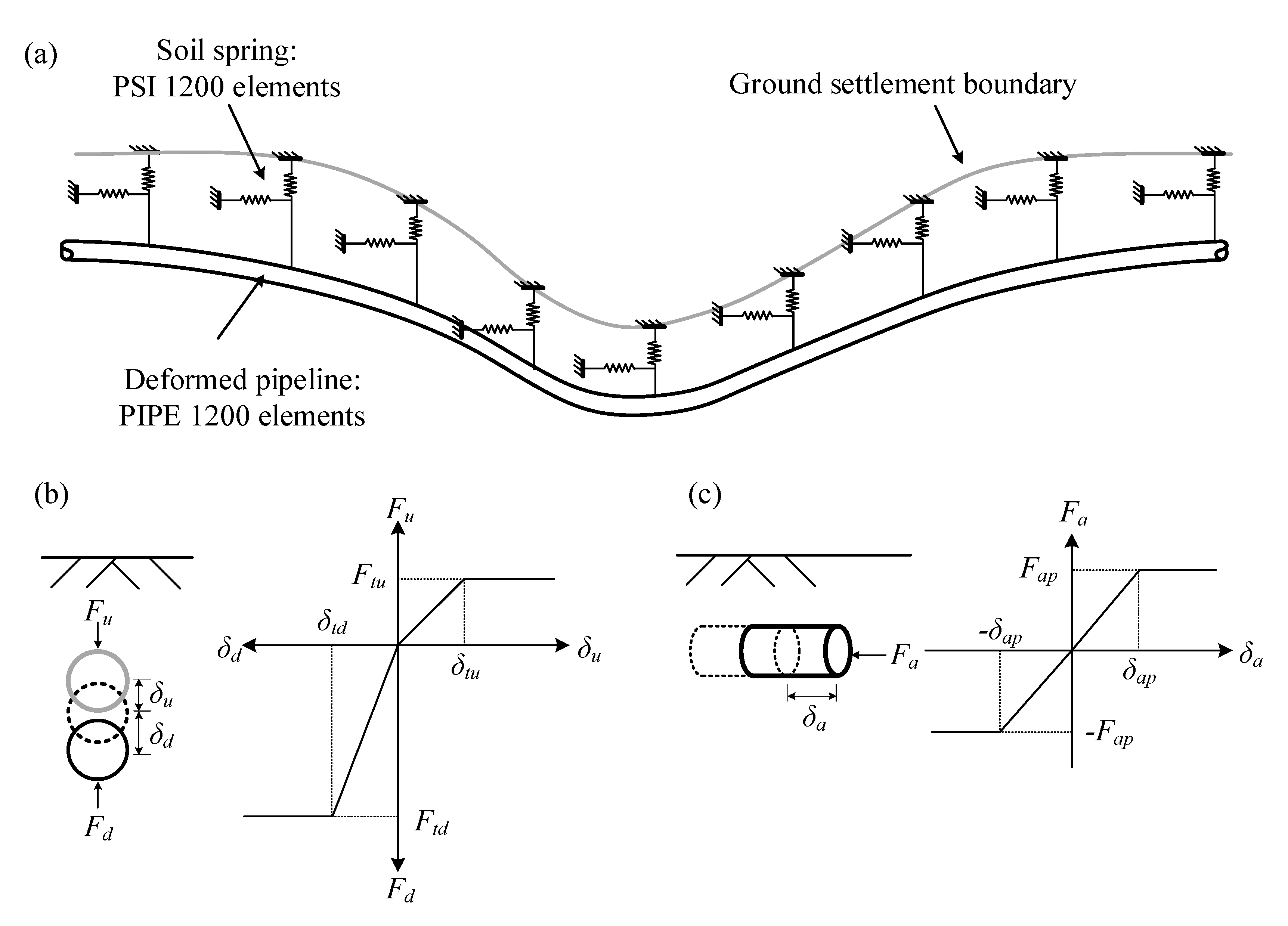
3. Pipe–Soil–Tunnel Interaction Model

The ground settlement boundary predicted using the modified method is applied to the finite element pipe–soil–tunnel interaction model, as shown in Figure 3a. The model is established using ABAQUS 6.14. The pipeline is modeled using 1200 numbers of beam (PIPE31). The pipe–soil interaction is reflected by the compression and extension of soil springs along the pipeline, characterized by 1200 numbers of pipe–soil interaction (PSI) elements. Three directions of relative pipe–soil displacements are considered, i.e., the upward, downward, and axial directions. Thus, three different bilinear force–displacement relationships are considered in the simulation, as shown in Figure 3b,c. The soil resistances and relative displacement in the upward, downward, and axial directions are Fu, Fd, Fa and δu, δd, δa. The peak resistances and corresponding relative displacements are Ftu, Ftd, Fap and δtu, δtd, δap, respectively. The peak resistances can be estimated via Equation (7), in which Ncv and Nqv are uplift factors; Nc, Nq, and Nγ are bearing capacity factors; c is the cohesion of soil; and γ is the unit weight of soil. H and Dp are the burial depth and outer diameter of pipe, respectively, and α is the adhesion factor. K0 is the coefficient of pressure at rest, and δ is the interface friction angle for pipe and soil. The corresponding displacements can refer to ALA standard [27]. The values of Ncv, Nqv, Nc, Nq, and Nγ can also be obtained based on ALA standard [27].
{ F t u = N c v c D p + N q v γ H D p F t d = N c c D p + N q γ H D p + N γ γ D p 2 2 F a p = π D p α c + π D p H γ 1 + K 0 2 tan δ
The effectiveness of the modeling strategy is evaluated by comparing against the pipe–tunnel interaction centrifuge test measurements reported by Shi et al. [10]. In the test, an aluminum alloy pipeline with an outer diameter of 0.635 m (in prototype scale), length of 36.8 m, burial depth of 1.2 m, wall thickness of 0.066 m, and elastic modulus of 70 GPa was considered. The tunnel had an outer diameter of 6.08 m and burial depth of 12.04 m. The ground volume loss was about 2%. The soil friction angle was 31°, and unit weight was 15.19 kN/m3. The value of K was taken to be 0.3, and Dr as 0.7. Thus, i = 3.612 and maximum settlement Smax = 0.027 m can be obtained. According to ALA standard [27] and the calculation parameters mentioned above, the input parameters for soil springs can be obtained using Equation (7) and are listed in Table 1.
The variations in normalized ground surface settlement, S/D, and pipe bending strain, με, calculated using the finite element model are shown in Figure 4, accompanied by the results measured from centrifuge tests. As can be seen, both the maximum values of ground surface settlement and pipe bending strain appear in the centerline, and the values tends to zero when |x| increases further. The predicted normalized ground surface settlement is S/D = 0.44%, which is quite close to the measured result of 0.43%. The ground surface settlement curves also match relatively well with each other. The numerical result of maximum longitudinal pipe strain occurs at the maximum settlement position, with a value of 207 με, and the corresponding measurement is about 200 με. The numerical results of maximum negative strain are smaller than those of the measurements, but the general shapes of strain curves are relatively close to each other. In general, the finite element method provides a sufficient approximation of the measured values for the pipe–tunnel interaction centrifuge test. Note that only a single tunnel is considered here. Therefore, the numerical model is extended to reflect the twin-tunneling effects on buried pipelines in the following sections.

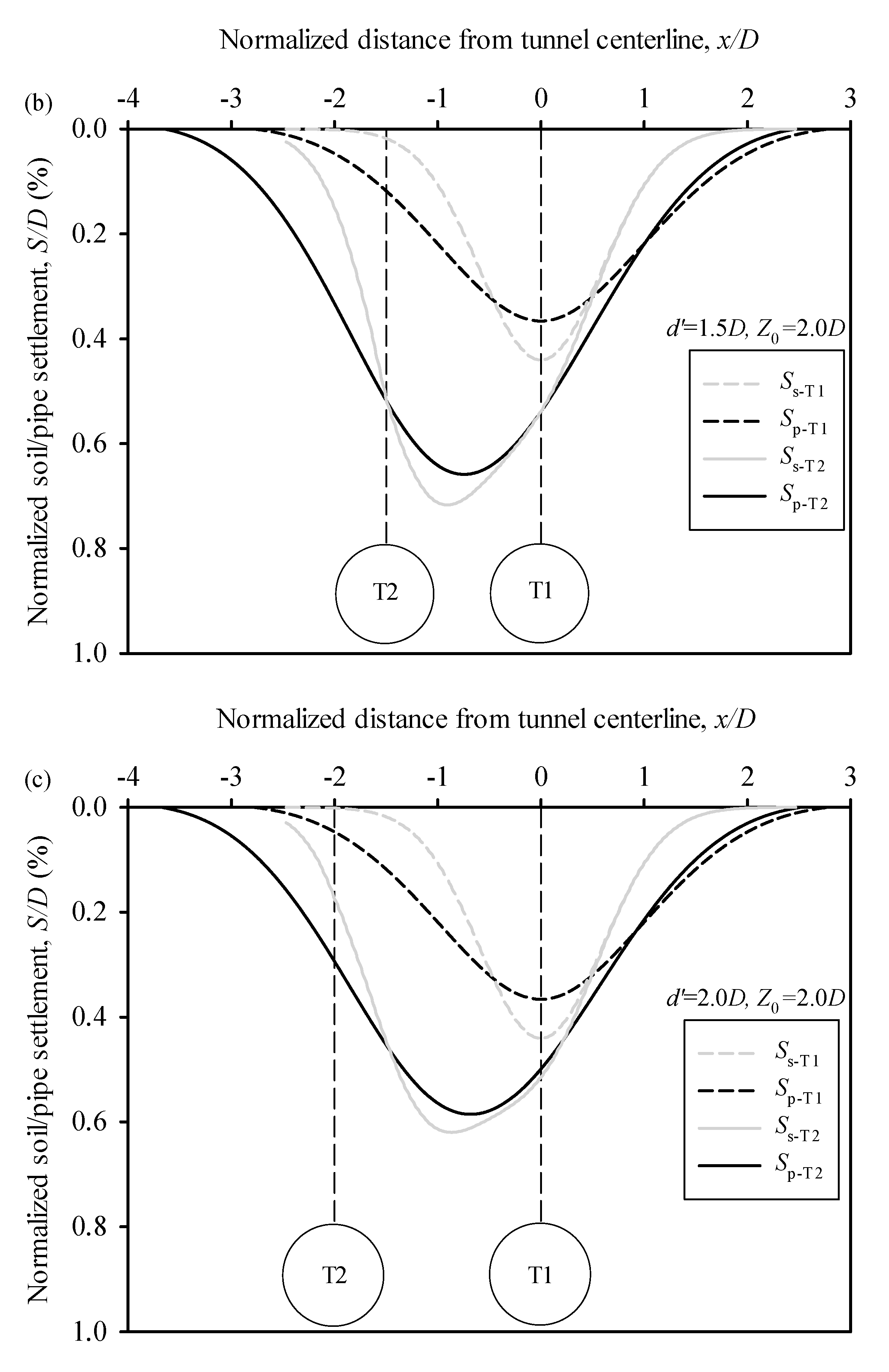
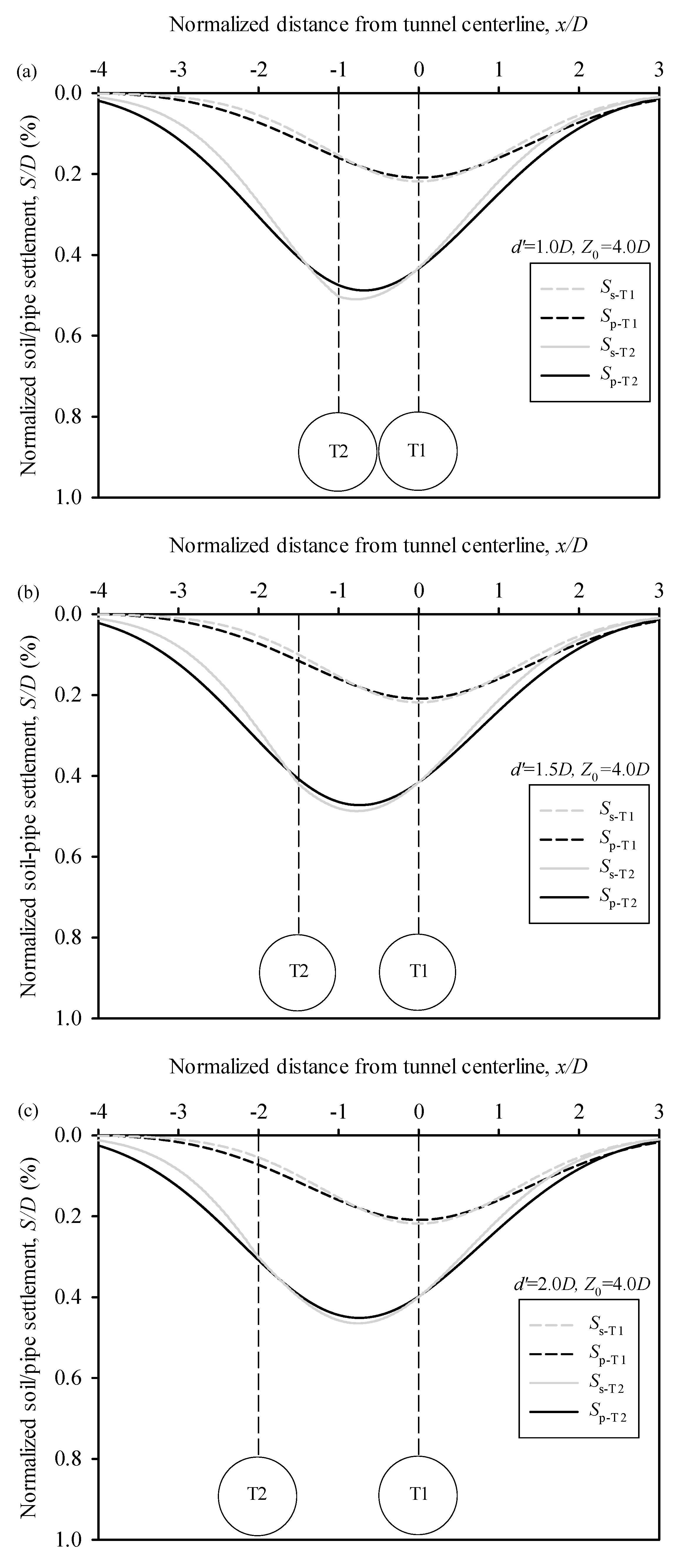
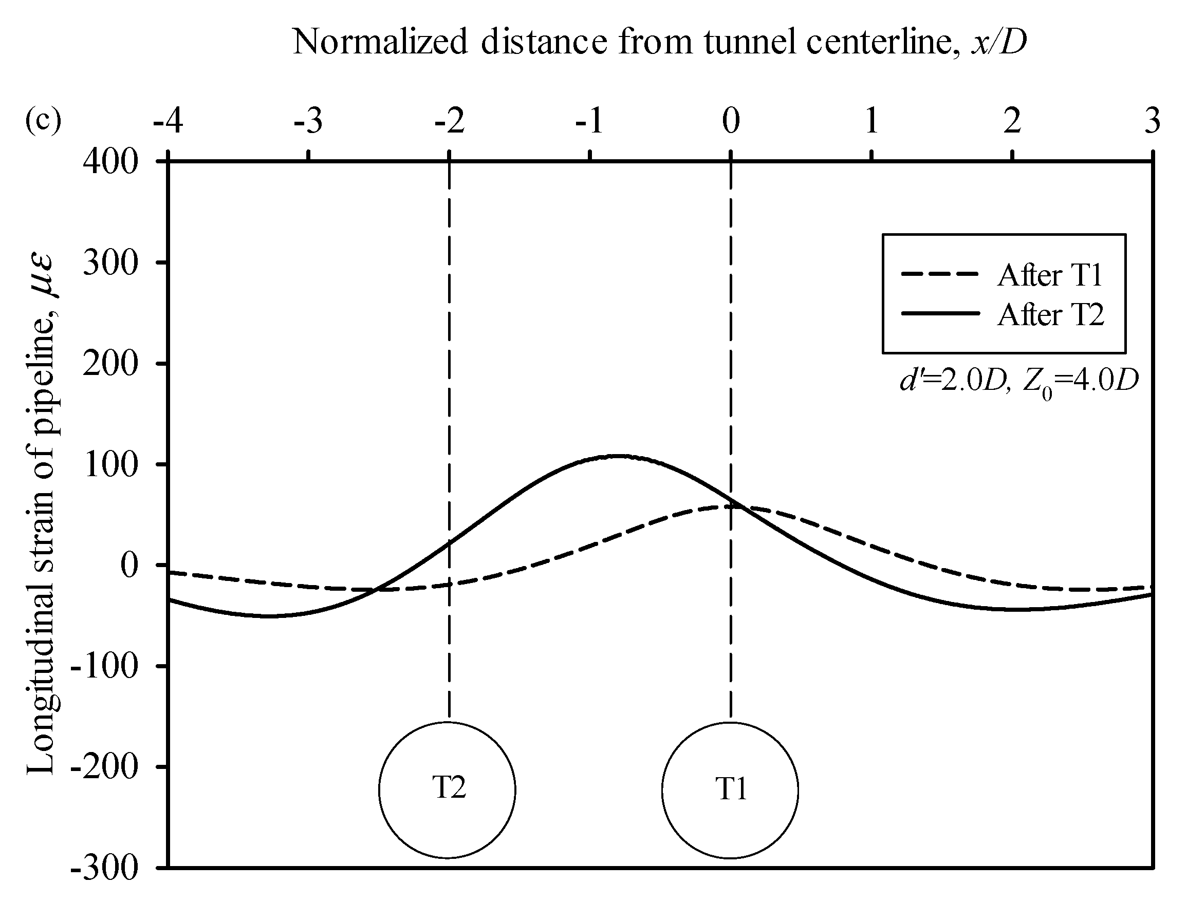
4. Parametric Analyses of Twin-Tunneling Effects on Buried Pipelines

Two tunnel burial depths and three twin-tunnel spaces are considered in this section, i.e., Z0 = 2.0D and 4.0D, d′ = 1.0D, 1.5D, and 2.0D (Table 2). The other dimensions and material properties of pipeline, soil, and tunnels are the same as in the previous section. The results of ground/pipeline settlement and pipeline bending strain are depicted in Figure 5, Figure 6, Figure 7 and Figure 8.
It can be seen from Figure 5 that under the tunnel depth of Z0 = 2.0D, the maximum ground settlement is relatively larger than that of buried pipelines after the tunneling, but the width of the pipe settlement trough is remarkably larger than that of the ground settlement. With the decrease in twin-tunnel space from d′ = 1.0D to d′ = 2.0D, the maximum pipe settlement after the second tunneling Sp-t2 decreases correspondingly from S/D = 0.72% to 0.59%. The maximum Sp-t2 locates directly above the second tunnel when d′ = 1.0D, and the position moves gradually to the midspan between the two tunnels when d′ = 2.0D.
Figure 6 shows the settlement profiles of ground surface and buried pipelines under a tunnel depth of Z0 = 4.0D. It can be seen that with the increment in tunnel burial depth, the differences between the ground and pipeline settlements after both the first and second tunneling all become negligible, especially when then tunnel space is relatively large. In addition, both soil and pipeline settlements are reduced significantly when the tunnel burial depth is relatively large. For instance, when d′ = 1.0D, the maximum normalized soil and pipeline settlements after the second tunneling are S/D = 0.51% and 0.48%, respectively. When d′ increases to 2.0D, the corresponding results are S/D = 0.46% and 0.45%. The results imply that the increase in the tunnel burial depth is helpful to protect the pipeline performance when an adjacent tunneling condition is encountered.
The numerical results of longitudinal pipe strain after the tunneling process are shown in Figure 7 and Figure 8. It can be seen that under a relatively shallow tunnel depth, the response of buried pipeline changes significantly during the variation in the tunnel space. Under the condition of Z0 = 2.0D and d′ = 1.0D, the maximum pipe strain increases remarkably from 202 με to 324 με when the second tunnel is constructed, and the position of the peak strain moves from the top of tunnel 1 to the top of tunnel 2. With the increment in tunnel space from d′ = 1.0D to 2.0D, the peak pipe strain after the second tunneling decreases gradually to 216 με, and the peak strain occurs at the midspan of the two tunnels. When the tunnel depth is increased to Z0 = 4.0D, the variation in tunnel space does not seem to have obvious effects on the longitudinal pipe strain results. Under the studied tunnel space conditions, the pipe strain only slightly changes between 134 με and 108 με.

5. Prediction of Pipeline Response under Twin-tunneling Condition

5.1. Maximum Pipeline Response

Effective prediction methods for pipeline response under the single-tunnel condition have been investigated in previous studies [1,2,7,13,15,16,17,18,19,28,29,30]. For instance, Wang et al. [7] conducted a series of beam-on-spring finite element analyses, and then a simplified relationship between the maximum pipe curvature and the relative pipe–soil stiffness was proposed, the results of which are plotted in Figure 9. On the other hand, appropriate prediction methods for twin-tunneling conditions are still rare, and are thus investigated in this section.
Figure 5, Figure 6, Figure 7 and Figure 8 have revealed that after the second tunneling, the ground and pipe response can be changed significantly. Therefore, the existing assessment for the single-tunnel condition cannot be applied directly on the twin-tunnel condition, and modifications are needed. Considering that the maximum settlement and bending strain positions will be biased after the second tunneling, a modified Gaussian curve function for ground settlement which can reflect the change in the maximum settlement position is proposed, as shown below:
S ( x ) = S max exp ( ( x b ) 2 2 i 2 )
in which b is the biased distance of the maximum settlement position, i is the distance to the inflection point, and Smax is the maximum settlement after the second tunneling. The value of Smax and the ground settlements can be estimated using the method introduced in the previous section. Then, the values of b and i can be obtained by curve-fitting. The results are plotted in Figure 9 for comparison. The pipe and ground curvatures are obtained from the finite element analysis. Ku and Kd represent the ratio between peak soil resistance and the corresponding relative pipe–soil displacement, details of which can be found in Wang et al. [7]. It can be seen that when the tunnel depth is relatively large, i.e., Z0 = 4D, the obtained results match quite well with the best-fitting curve provided by Wang et al. [7], and the change in twin-tunnel space does not affect the results significantly. When the tunnel depth is relatively small, i.e., Z0 = 2D, with the increase in tunnel space, the dimensionless pipe–soil response result generally moves to the left, indicating that the existing best-fitting curve becomes relatively conservative when it is used to predict the pipeline performance under twin-tunneling conditions.

5.2. Prediction of Longitudinal Pipeline Bending Response

The dimensionless plot in Figure 9 can provide a conservative estimation of pipeline response under twin-tunneling conditions, but it cannot reflect the change in pipeline performance with the twin-tunnel space. Klar and Marshall [16] proposed that the Gaussian curve function can also be used to fit the settlement of a pipeline under single-tunneling conditions; thus, the pipe settlement u(x) and bending moment M(x) can be estimated as
{ u ( x ) = 2 β s max exp ( β x 2 i 2 ) M ( x ) = E p I p s max i 2 ( 2 β ) 3 / 2 exp ( β x 2 i 2 ) ( 1 2 β x 2 i 2 ) β = 0.5 0.1223 R 0.0974 arcsinh ( R ) R = E p I p E s i 3 r 0
in which β is the slope of the loge(u/smax)−(x/i)2 curve and R is the pipe–soil stiffness ratio, r0 is the pipe diameter, and Es is the elastic modulus of soil, according to Klar and Marshall [16]. Note that Equation (9) is used for the single-tunnel condition, i.e., smax and i are the maximum ground settlement and inflection point distance under the single-tunnel condition, which cannot be used directly for the twin-tunnel condition. In the previous section, the corresponding estimations for the twin-tunnel condition, i.e., stmax and it, and the bias b in Equation (8), are obtained. Therefore, Equation (9) can be rewritten for pipeline response under twin-tunnel conditions as Equation (10):
{ u ( x + b D ) = 2 β s t max exp ( β x 2 i t 2 ) M ( x + b D ) = E p I p s t max i t 2 ( 2 β ) 3 / 2 exp ( β x 2 i t 2 ) ( 1 2 β x 2 i t 2 )
in which D is the tunnel diameter. The predicted results are shown in Figure 10 and Figure 11. For comparison, the numerical results from the beam-on-spring modeling introduced in the previous section are also provided. It can be seen that after the modification, the predicted results match quite well with the numerical results, especially under relatively large tunnel burial depth conditions. Moreover, when the twin-tunnel space increases, both predicted and numerical results of peak pipe strain decrease correspondingly. For instance, when d′ = 1.0D and Z0 = 2.0D, the predicted and simulated peak pipe strains are 327 and 324 με, and they occur at about −0.64D and −0.84D, respectively, to Tunnel 1. When d′ increases to 2.0D, the peak pipe strains are 228 and 216 με, and occur at −0.68D and −0.80D, respectively, to Tunnel 1 (see Figure 10). Under the condition of Z0 = 2.0D, the values and positions of peak pipe strain from both methods are even closer to each other. When d′ = 1.0D, the peak pipe strains are 131 and 134 με, they locate at −0.63D and −0.79D to Tunnel 1. When d′ = 2.0D, the corresponding results are 112 and 108 με, −0.70D and −0.79D, respectively, for prediction and numerical simulation, as shown in Figure 11.
Figure 10 and Figure 11 show the effectiveness of the semi-empirical method for predicting the longitudinal pipe bending strain. The semi-empirical method is also convenient to use in practice. Once twin tunnels intersecting buried pipelines are encountered, engineering partitioners can firstly estimate the ground settlement based on Equation (6), then calculate the biased parameter and the distance to the inflection point in Equation (8) using curve fitting, and finally predict the pipe response according to Equation (10). The method can thus provide a simple and effective way to conduct a preliminary assessment of pipe safety and structural integrity under twin-tunneling effects.

6. Conclusions

With the development of underground infrastructure, it is inevitable for buried pipelines to cross differential ground settlement areas induced by tunneling effects. Twin tunnels are more frequently used in modern subway systems. The ground deformation and the corresponding pipe response under twin-tunneling effects are more significant than those under single-tunneling conditions. Therefore, this study focused on the pipe response under twin-tunneling effects and carried out a series of beam-on-spring finite element analyses. Based on that, a semi-empirical approach is proposed, which can quickly and effectively provide a prediction on the longitudinal pipe bending behavior under twin-tunneling effects. The following conclusions can be drawn.
Compared to single-tunneling conditions, both the position and value of maximum ground settlement and pipe longitudinal response are changed significantly under twin-tunneling conditions. Comparatively, the maximum pipe bending strain increases with the decrease in tunnel depth and twin-tunnel space.
The maximum pipe curvature and the relative pipe–soil stiffness relationship follows the recommended functions when the twin tunnels’ depth is relatively large. When the tunnel depth is small, the pipe–soil response results move generally to the left of the recommended dimensionless curves when the twin-tunnel space decreases.
The maximum ground settlement position is biased due to the second tunneling. The biased distance and the distance to inflection point of the final settlement curve can be obtained by curve fitting. Then, the longitudinal pipe bending strain can be obtained. The predicted values match quite well with the numerical results.

Author Contributions

Conceptualization, J.W. and M.Y.; methodology, M.Y. and Q.C.; software, J.A. and R.G.; validation, S.Z. (Shenyi Zhang), Q.X. and R.G.; formal analysis, J.A.; investigation, Q.X.; resources, Q.C.; data curation, S.Z. (Shenyi Zhang); writing—original draft preparation, J.A.; writing—review and editing, M.Y. and S.Z. (Sizhuo Zheng); visualization, M.Y.; supervision, M.Y.; project administration, J.W.; funding acquisition, J.W. All authors have read and agreed to the published version of the manuscript.

Funding

This research was funded by the Postdoctoral Research Foundation of China (2021M702400), the Natural Science Foundation for Colleges and Universities in Jiangsu Province (21KJB560018), and CCDI (Suzhou) Exploration & Design Consulting Co. LTD (grant number: T2020JYF001).

Institutional Review Board Statement

Not applicable.

Informed Consent Statement

Not applicable.

Data Availability Statement

Not applicable.

Acknowledgments

The financial support is gratefully acknowledged.

Conflicts of Interest

The authors declare no conflict of interest.

References

  1. Vorster, T.E.B.; Klar, A.; Soga, K.; Mair, J.R. Estimating the Effects of Tunneling on Existing Pipelines. J. Geotech. Geoenviron. Eng. 2005, 131, 1399–1410. [Google Scholar] [CrossRef]
  2. Klar, A.; Marshall, A.M.; Soga, K.; Mair, R.J. Tunnelling effect on jointed pipelines. Can. Geotech. J. 2008, 45, 131–139. [Google Scholar] [CrossRef]
  3. Shi, P. Seismic wave propagation effects on buried segmented pipelines. Soil Dyn. Earthq. Eng. 2015, 72, 89–98. [Google Scholar] [CrossRef]
  4. Vasseghi, A.; Haghshenas, E.; Soroushian, A.; Rakhshandeh, M. Failure analysis of a natural gas pipeline subjected to landslide. Eng. Fail. Anal. 2021, 119, 105009. [Google Scholar] [CrossRef]
  5. Qin, X.; Ni, P.; Wang, Y.; Du, Y.-J. Mechanical response estimation of jointed rigid pipes under normal fault rupture. Soil Dyn. Earthq. Eng. 2021, 146, 106754. [Google Scholar] [CrossRef]
  6. Qin, X.; Wang, Y.; Fu, C. Joint Kinematics and Sealing Capacity Assessment of Ductile Iron Pipes under Abrupt Transverse Ground Movements. Can. Geotech. J. 2022, 59, 342–358. [Google Scholar] [CrossRef]
  7. Wang, Y.; Shi, J.; Ng, C.W.W. Numerical modeling of tunneling effect on buried pipelines. Can. Geotech. J. 2011, 48, 1125–1137. [Google Scholar] [CrossRef]
  8. Ni, P.; Mangalathu, S. Fragility analysis of gray iron pipelines subjected to tunneling induced ground settlement. Tunn. Undergr. Sp. Technol. 2018, 76, 133–144. [Google Scholar] [CrossRef]
  9. Marshall, A.M.; Klar, A.; Mair, R.J. Tunneling beneath Buried Pipes: View of Soil Strain and Its Effect on Pipeline Behavior. J. Geotech. Geoenviron. Eng. 2010, 136, 1664–1672. [Google Scholar] [CrossRef]
  10. Shi, J.; Wang, Y.; Ng, C.W.W. Three-Dimensional Centrifuge Modeling of Ground and Pipeline Response to Tunnel Excavation. J. Geotech. Geoenviron. Eng. 2016, 142, 04016054. [Google Scholar] [CrossRef]
  11. Li, H.-J.; Zhu, H.-H.; Wu, H.-Y.; Zhu, B.; Shi, B. Experimental investigation on pipe-soil interaction due to ground subsidence via high-resolution fiber optic sensing. Tunn. Undergr. Sp. Technol. 2022, 127, 104586. [Google Scholar] [CrossRef]
  12. Klar, A.; Marshall, A.M. Shell versus beam representation of pipes in the evaluation of tunneling effects on pipelines. Tunn. Undergr. Sp. Technol. 2008, 23, 431–437. [Google Scholar] [CrossRef]
  13. Shi, J.; Wang, Y.; Ng, C.W.W. Numerical parametric study of tunneling-induced joint rotation angle in jointed pipelines. Can. Geotech. J. 2016, 53, 2058–2071. [Google Scholar] [CrossRef]
  14. Wham, B.P.; Argyrou, C.; O’Rourke, T.D. Jointed pipeline response to tunneling-induced ground deformation. Can. Geotech. J. 2016, 53, 1794–1806. [Google Scholar] [CrossRef] [Green Version]
  15. Klar, A.; Vorster, T.E.B.; Soga, K.; Mair, R.J. Soil-pipe interaction due to tunnelling: Comparison between Winkler and elastic continuum solutions. Géotechnique 2005, 55, 461–466. [Google Scholar] [CrossRef]
  16. Klar, A.; Marshall, A.M. Linear elastic tunnel pipeline interaction: The existence and consequence of volume loss equality. Géotechnique 2015, 65, 788–792. [Google Scholar] [CrossRef]
  17. Huang, M.; Zhou, X.; Yu, J.; Leung, C.F.; Tanb, J.Q.W. Estimating the effects of tunnelling on existing jointed pipelines based on Winkler model. Tunn. Undergr. Sp. Technol. 2019, 86, 89–99. [Google Scholar] [CrossRef]
  18. Lin, C.; Huang, M. Tunnelling-induced response of a jointed pipeline and its equivalence to a continuous structure. Soils Found. 2019, 59, 828–839. [Google Scholar] [CrossRef]
  19. Lin, C.; Huang, M.; Nadim, F.; Liu, Z. Tunnelling-induced response of buried pipelines and their effects on ground settlements. Tunn. Undergr. Sp. Technol. 2020, 96, 103193. [Google Scholar] [CrossRef]
  20. Chapman, D.N.; Ahn, S.K.; Hunt, D.V.L. Investigating ground movements caused by the construction of multiple tunnels in soft ground using laboratory model tests. Can. Geotech. J. 2007, 44, 631–643. [Google Scholar] [CrossRef]
  21. Kannangara, K.K.P.M.; Ding, Z.; Zhou, W.-H. Surface settlements induced by twin tunneling in silty sand. Undergr. Space 2022, 7, 58–75. [Google Scholar] [CrossRef]
  22. Zheng, G.; Wang, R.; Lei, H.; Zhang, T.; Guo, J.; Zhou, Z. Relating twin-tunnelling-induced settlement to changes in the stiffness of soil. Acta Geotech. 2022. [Google Scholar] [CrossRef]
  23. Islam, M.S.; Iskander, M. Twin tunnelling induced ground settlements: A review. Tunn. Undergr. Sp. Technol. 2021, 110, 103614. [Google Scholar] [CrossRef]
  24. Ma, S.; Shao, Y.; Liu, Y.; Jiang, J.; Fan, X. Responses of pipeline to side-by-side twin tunnelling at different depths: 3D centrifuge tests and numerical modelling. Tunn. Undergr. Space Technol. 2017, 66, 157–173. [Google Scholar] [CrossRef]
  25. Peck, R.B. Deep excavations and tunneling in soft ground. Proc. 7th ICSMFE 1969, 1969, 225–290. [Google Scholar]
  26. Avgerinos, V.; Potts, D.; Standing, J.; Wan, M. Predicting tunnelling-induced ground movements and interpreting field measurements using numerical analysis: Crossrail case study at Hyde Park. Géotechnique 2018, 68, 31–49. [Google Scholar] [CrossRef] [Green Version]
  27. ALA. Guidelines for the Design of Buried Steel Pipe; ASCE: Reston, VA, USA, 2005. [Google Scholar]
  28. Klar, A.; Vorster, T.E.B.; Soga, K.; Mair, R.J. Elastoplastic Solution for Soil-Pipe-Tunnel Interaction. J. Geotech. Geoenviron. Eng. 2007, 133, 782–792. [Google Scholar] [CrossRef]
  29. Klar, A.; Elkayam, I.; Marshall, A.M. Design Oriented Linear-Equivalent Approach for Evaluating the Effect of Tunneling on Pipelines. J. Geotech. Geoenviron. Eng. 2016, 142, 04015062. [Google Scholar] [CrossRef]
  30. Klar, A. Elastic Continuum Solution for Tunneling Effects on Buried Pipelines Using Fourier Expansion. J. Geotech. Geoenviron. Eng. 2018, 144, 04018062. [Google Scholar] [CrossRef]
Figure 1. Schematic view of side-by-side tunneling effect on buried pipeline.
Sustainability 15 00353 g001
Figure 2. Estimation of ground settlement of side-by-side tunnels.
Sustainability 15 00353 g002
Figure 3. Illustration of beam-on-spring FE model for tunneling effect on pipeline: (a) idealized representation of soil with discrete springs, (b) transverse vertical spring, (c) axial spring.
Sustainability 15 00353 g003
Figure 4. Comparison with test measurements: (a) ground settlement, (b) longitudinal pipe strain.
Sustainability 15 00353 g004
Figure 5. Numerical results of pipeline settlement under Z0 = 2.0D: (a) d = 1.0D, (b) d = 1.5D, (c) d = 2.0D.
Sustainability 15 00353 g005aSustainability 15 00353 g005b
Figure 6. Numerical results of pipeline settlement under Z0 = 4.0D: (a) d = 1.0D, (b) d = 1.5D, (c) d = 2.0D.
Sustainability 15 00353 g006
Figure 7. Numerical results of longitudinal pipeline strain under Z0 = 2.0D: (a) d = 1.0D, (b) d = 1.5D, (c) d = 2.0D.
Sustainability 15 00353 g007aSustainability 15 00353 g007b
Figure 8. Numerical results of longitudinal pipeline strain under Z0 = 4.0D: (a) d = 1.0D, (b) d = 1.5D, (c) d = 2.0D.
Sustainability 15 00353 g008aSustainability 15 00353 g008b
Figure 9. Comparison of numerical results against a dimensionless plot.
Sustainability 15 00353 g009
Figure 10. Longitudinal pipe stain from predicted results and numerical simulation under Z0 = 2.0D: (a) d = 1.0D, (b) d = 1.5D, (c) d = 2.0D.
Sustainability 15 00353 g010aSustainability 15 00353 g010b
Figure 11. Longitudinal pipe stain from predicted results and numerical simulation under Z0 = 4.0D: (a) d = 1.0D, (b) d = 1.5D, (c) d = 2.0D.
Sustainability 15 00353 g011aSustainability 15 00353 g011b
Table 1. Input parameters for soil springs.
Ftu (N/m)24,644.74δap (m)0.004
Ftd (N/m)368,613.54Nv1.68
Fap (N/m)25,058.35Nq20.63
δtu (m)0.023Nγ21.76
δtd (m)0.064K00.5
Table 2. Summary of parameters.
ItemParameterValue
TunnelBurial depth, Z02.0D, 4.0D
Space, d′1.0D, 1.5D, 2.0D
Diameter, D6.08 m
PipeDiameter, Dp0.635 m
Wall thickness, tp0.066 m
Burial depth, H1.2 m
Young’s modulus, Ep70 Gpa
SoilFriction angle, φ31°
Unit weight, γ15.19 kN/m3
Disclaimer/Publisher’s Note: The statements, opinions and data contained in all publications are solely those of the individual author(s) and contributor(s) and not of MDPI and/or the editor(s). MDPI and/or the editor(s) disclaim responsibility for any injury to people or property resulting from any ideas, methods, instructions or products referred to in the content.

