Abstract
Ensuring the stability of surrounding rock while conducting pressure relief is key to roadway stability control and preventing rock burst. In this paper, segmented enlarged-diameter borehole destressing technology is proposed. The stress distribution around the borehole is analysed based on the theory of elasto-plastic mechanics, and the mechanism of pressure relief for segmented enlarged-diameter boreholes is studied. Secondly, The effects of the diameter of enlarged-diameter section, length of the enlarged-diameter section, and borehole space on pressure relief and roadway deformation were investigated. Finally, the optimal drilling parameters for Tangkou coal mine 6307 working face are analysed. The key parameters of segmented enlarged-diameter borehole pressure relief technology for the 6307 working face were determined and applied in field practice. Field monitoring results showed that the accumulated energy can be effectively reduced using segmented enlarged-diameter pressure relief boreholes, effectively controlling roadway deformation and providing reference for rock burst prevention and roadway stability control.
1. Introduction
With the gradual depletion of shallow resources, deep mining in eastern China as well as parts of central and western China has become commonplace (the average mining depth has reached 800–1000 m) [1,2,3,4,5,6]. The occurrence frequency and damage degree of coal and rock dynamic disasters increase with increasing mining depth (e.g., rock burst, coal and gas outburst, etc.). Rock burst is a typical coal mine dynamic disaster, which violently releases deformation energy, throwing out coal and rock, causing hydraulic support damage, rib spalling, and roof collapse [7]. In recent years, several rock burst accidents have successively occurred in China [8]. Rock burst has become one of the primary disaster types seriously restricting the safety production of mines.
In order to prevent rock burst, numerous researchers have made important contributions to rock burst monitoring, early warning, and control [4,9,10,11,12,13,14]. Mohammadali [15] estimate the rockburst potentials in a real case study mine combined with conventional and numerical methods. Previous studies have showed that stress is the key factor of rock burst occurrence. Therefore, before the working face is laid out, the first step is to adopt a reasonable development layout and mining method to reduce the influence of geological formations on the working face [16,17]. Victor [18] modernised the pillarless system by introducing a third roadway as a pressure relief roadway to protect the working face roadway from the support pressure during mining of the adjacent slab. For the high stress area that has been formed, pressure relief should be conducted on any high stress areas, including coal seam blasting pressure relief, high-pressure water injection, and large diameter borehole pressure relief [19]. In order to reduce the degree of stress concentration in the coal body, Dou et al. [20] proposed the theory of strength weakening using blasting pressure relief. Piotr [21] presents Polish experience in rockburst hazard assessment with the use of geomechanical method, as well as some solutions and examples of such analyses. Konicek [22] presented a case study of destress blasting and evaluated the effectiveness of rockburst prevention. Saeed [23] uses a fully coupled 3D finite element model of hydraulic fracturing in permeable rocks to investigate the interaction between multiple simultaneous and continuous hydraulic fractures. However, for mining roadways, improper blasting may also induce dynamic disasters such as rock burst and achieving the ideal pressure relief using coal seam water injection is difficult. Large diameter borehole pressure relief is an effective method to reduce the stress concentration for high stress areas. At present, this method has been widely used in coal mines and has become one of the primary methods of controlling rock burst disasters in coal mines.
Large diameter borehole pressure relief can transfer high stresses from the roadway side to the deep coal body. It has a relatively simple construction process, low cost, easy operation, and little impact on production [24]. Jia et al. [25] studied the pressure relief mechanism of large diameter boreholes using laboratory tests and numerical simulation. Zhang et al. [26] studied the variation of uniaxial compressive strength and energy dissipation index of coal after drilling and analyzed the characteristics of crack growth in coal. The above research is of great significance to understanding the mechanism behind large diameter borehole pressure relief.
The conventional large diameter borehole pressure relief method is plagued by insufficient pressure relief (rock burst still occurs after pressure relief) and excessive pressure relief (the strength of the original anchor layer will be damaged after pressure relief). Therefore, researchers put forward an integrated method of pressure relief and surrounding rock reinforcement, named ‘strong pressure relief and strong support. Tan et al. [27] examined the “relief and supporting” cooperative control mechanism of deep coal roadway and developed a “relief and supporting” cooperative control technology. Ensuring the stability of shallow surrounding rock and the associated support system while conducting proper pressure relief is key to safely controlling rock burst. For this reason, some scholars proposed a segmented enlarged-diameter borehole destressing technology and analyzed the effect of the diameter of the enlarged-diameter section on pressure relief effect and support system [28]. However, the above study only examined factors affecting the pressure relief due to the enlarged-diameter section using numerical simulation. The pressure relief mechanism of the segmented enlarged-diameter boreholes should be further analyzed.
This study first calculated and analyzed stress distribution characteristics around the segmented enlarged-diameter borehole as well as the position of enlarged-diameter section. Then, the effect of parameters, such as the diameter of enlarged-diameter section, length of enlarged-diameter section, and borehole space, on pressure relief and roadway deformation were further analyzed. Based on theoretical analysis and numerical simulation results, the key pressure relief parameters of the segmented enlarged-diameter borehole were determined and applied in the mining roadway of 6307 working face of the Tangkou Coal mine. The results provide reference for rock burst prevention and control as well as roadway stability control.
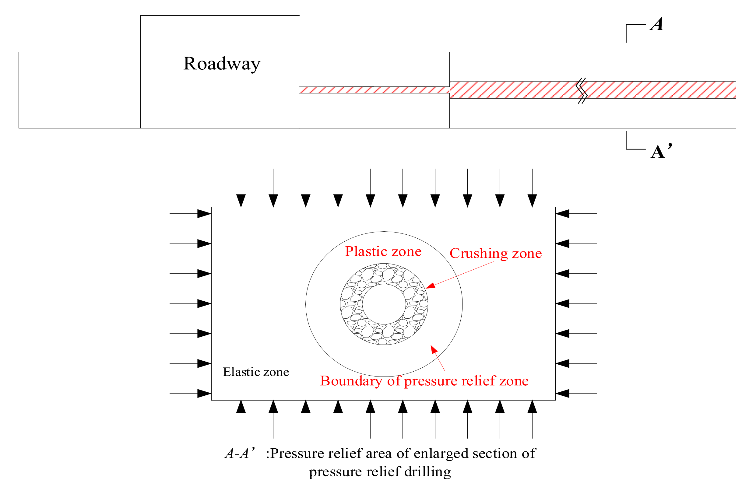
2. Destressing Mechanism of Segmented Enlarged-Diameter Borehole
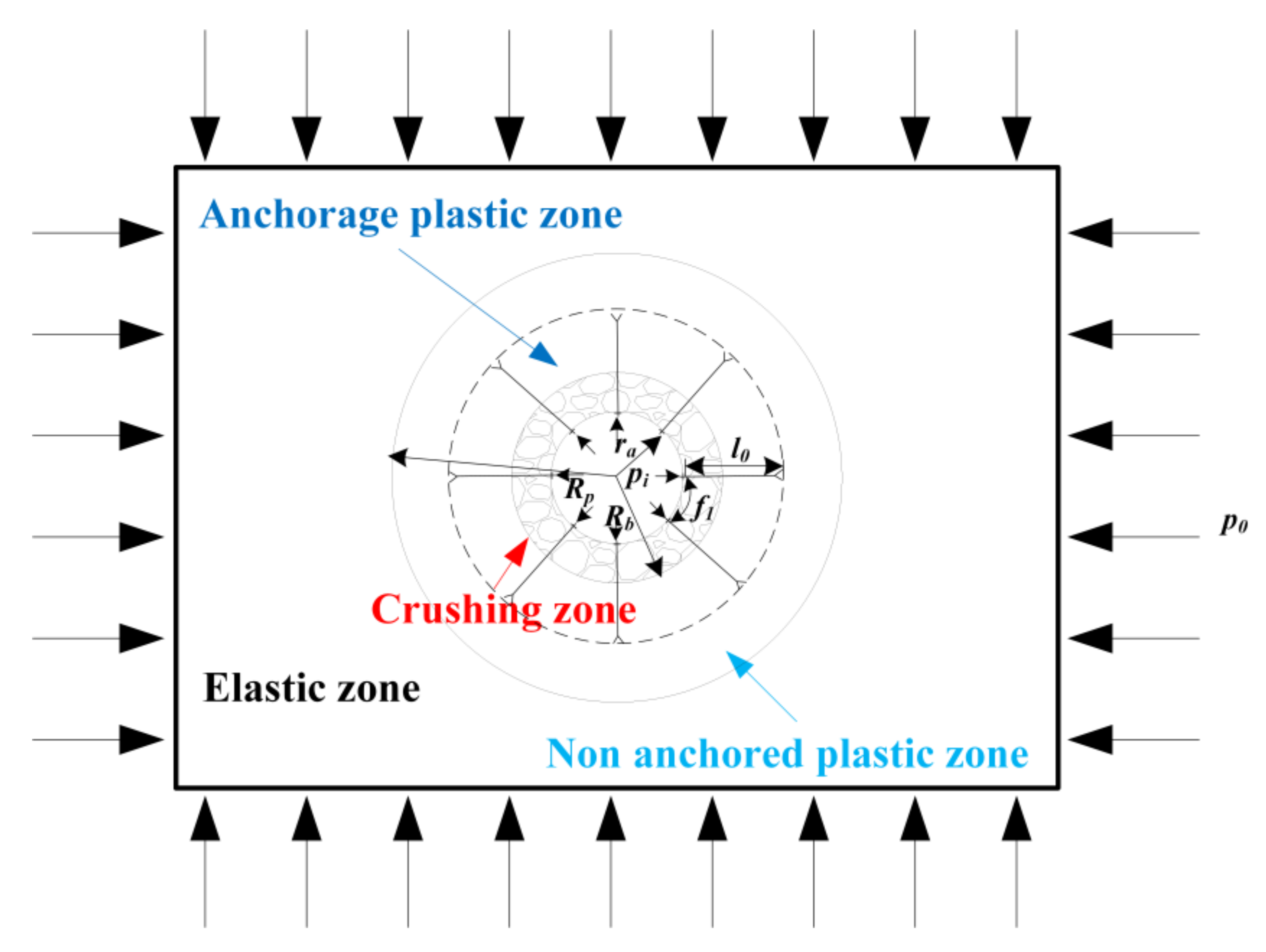
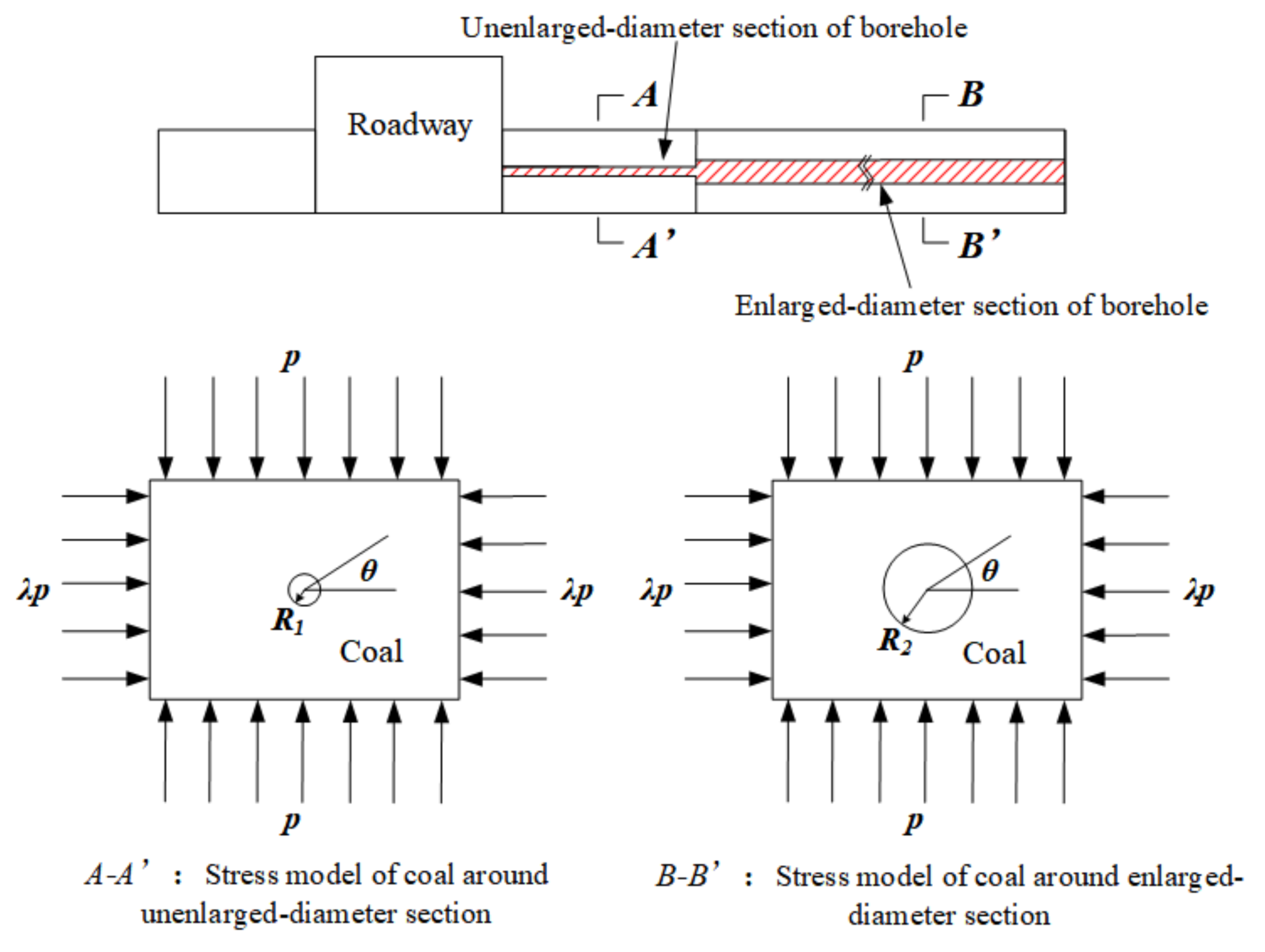
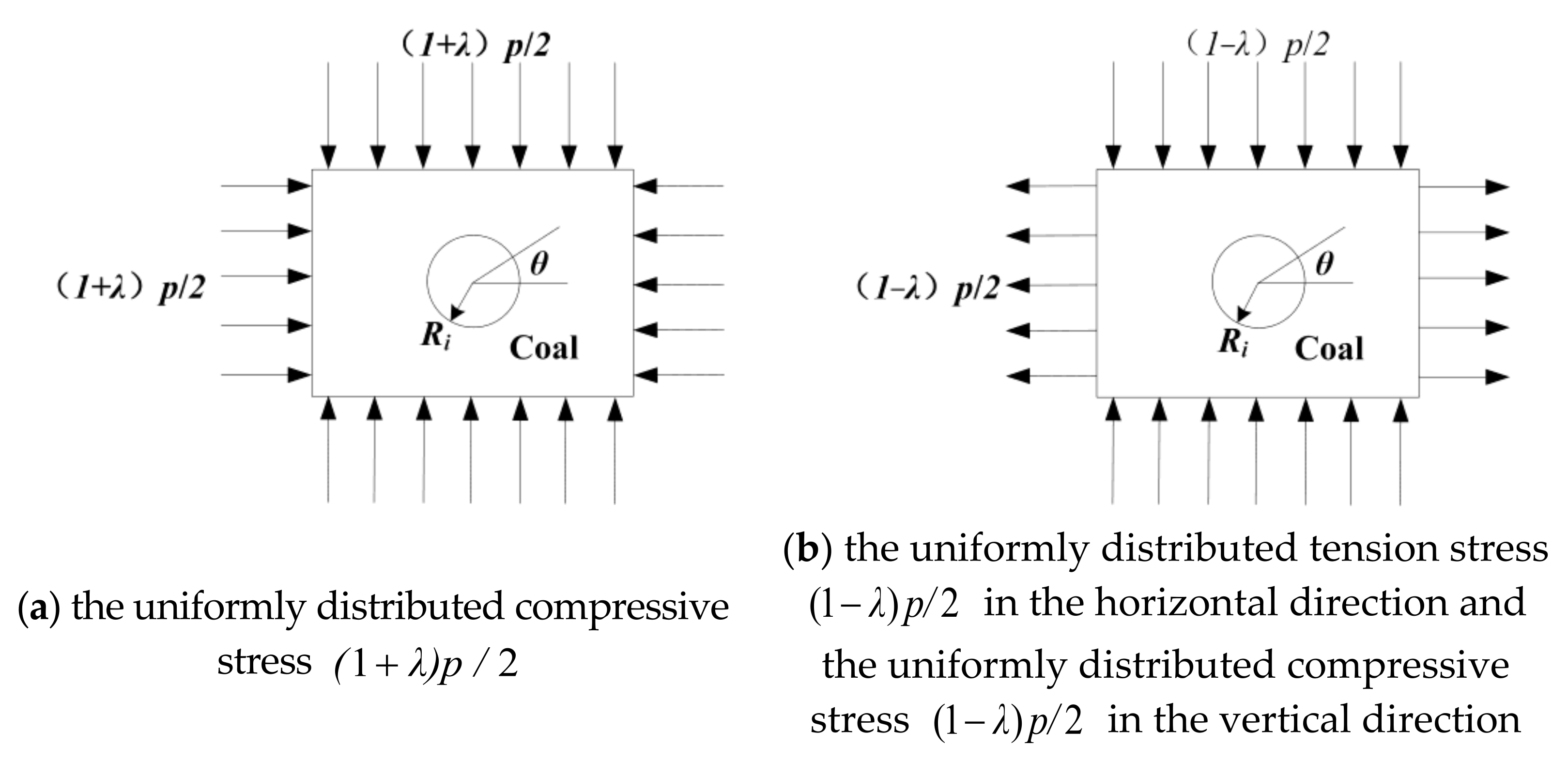
2.1. Stress Distribution Characteristics around the Segmented Enlarged-Diameter Borehole
Numerous researchers have examined the stress distribution around circular holes. Kirsch [29] deduced the two-dimensional stress distribution solution around a circular hole in an elastic plate. Jaeger et al. [30] further developed the Kirsch equation. For a long time, the modified Fenner formula [31] or Castenet [32] solution was used to determine radius of the plastic zone around a circular hole, and plastic zone theory was widely used in surrounding rock with softening and dilatancy.
When solving the boundary equation for the pressure relief zone, the coal around the borehole is assumed to be in an elastic state, and the yield of the coal under the stress condition is determined according to the plastic condition. The basic assumptions are lilsted as follows: (1) The coal body where the pressure relief borehole located is continuous, homogenous, isotropic, and linear elastic; (2) The axial direction of the pressure relief borehole is infinite; (3) The coal properties are consistent in the axial direction of the pressure relief borehole.
The segmented enlarged-diameter borehole is divided into an unenlarged-diameter section and enlarged-diameter section (Figure 1). The enlarged-diameter section is located in the elastic zone, which was outside the anchorage layer of the surrounding rock. The axial length of the pressure relief borehole is much greater than its radius, so the borehole can be analyzed as a plane strain problem. The vertical and horizontal stresses subjected to the pressure relief borehole are simplified as uniformly distributed stresses (Figure 1).
Figure 1.
Stress model of coal around boreholes.
According to the superposition of elasticity, the load of an unenlarged-diameter section and enlarged-diameter section of borehole can be divided into two parts: the uniformly distributed compressive stress (Figure 2a); the uniformly distributed tension stress in the horizontal direction and the uniformly distributed compressive stress in the vertical direction (Figure 2b).
Figure 2.
Borehole stress decomposition based on superposition.
According to the classical solution of elastic mechanics, the expression for the stress component of coal around the borehole in polar coordinates is:
where: p—Vertical stress on the coal body, MPa;
—The polar angle of the coal body at any point around the drill hole; σr—Radial stress at a point of coal around the borehole, MPa;
σθ—Tangential stress at a point of coal around the borehole, MPa;
τrθ, τθr—Shear stress at a point of coal around the borehole, MPa;
Ri—Radius (radius of unenlarged-diameter section is R1 and radius of enlarged-diameter section is R2), m;
λ—Side pressure coefficient;
r—The distance from a point of coal to the borehole center.
For the stress situation shown in Figure 2b, according to the classical solution of elastic mechanics, the expression for the stress component of coal around the borehole is:
The stress components in Figure 2 are superimposed to obtain the polar coordinate stress components around the borehole under the load in Figure 1:
Due to stress concentration at the edge of the borehole, the coal around the borehole forms a broken zone, a plastic zone, and an elastic zone (Figure 3). The broken zone and the plastic zone around the borehole are collectively called the pressure relief zone, and the boundary line of the plastic zone is the boundary line of the borehole pressure relief zone.
Figure 3.
Borehole pressure relief zone diagram.
According to Equation (3), the expression for the principal stress at a point of coal around the borehole is:
where: σ1, σ3—the maximum and minimum principal stresses, MPa.
According to the Mohr-Coulomb criterion, the yield conditions at a point of coal around the borehole is:
where: c—Coal cohesion, MPa;
φ—Internal friction angle.
Substituting Equation (3) into Equation (5) gives the boundary line equation of the coal plastic zone around the borehole:
where: ;
;
;
;
;
r—Radius of pressure relief zone.
According to Equation (6), the distribution range of the pressure relief zone around the borehole is related to the vertical stress P, lateral pressure coefficient γ, borehole radius Ri, cohesion c of the coal, and internal friction angle φ.
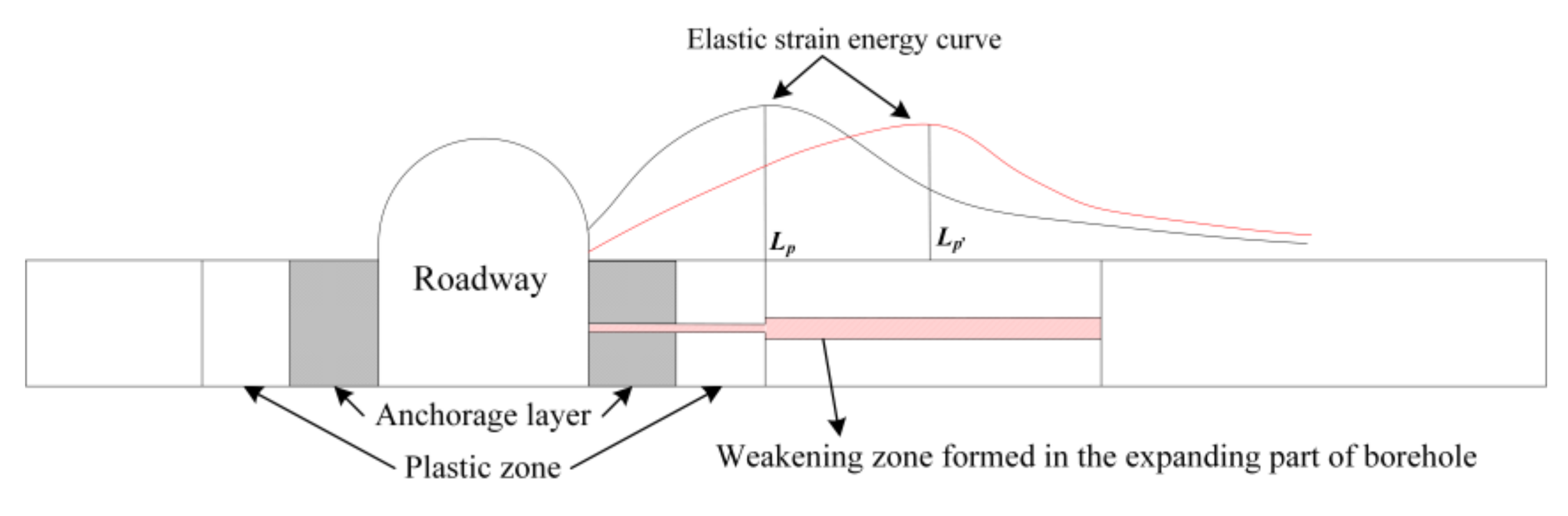
2.2. Determination of Segmented Enlarged-Diameter Position of Large Diameter Pressure Relief Boreholes
Determining the segmented enlarged-diameter position of the pressure relief borehole is of great significance. Surrounding rock under bolt support is divided into elastic zone, non-anchoring plastic zone, anchoring plastic zone, and anchoring broken zone (Figure 4). In the figure, the roadway radius is ra, the radius of crushing zone is Rb, the radius of plastic zone is Rp, the effective anchoring length of bolt is l0, and the annular distance of bolt is f1. There is assumed to be no slip between the bolt and the surrounding rock. The stress of the original rock is P0, and the uniform support resistance provided by the roadway support is Pi. Based on the Mohr-Coulomb criterion, the radius of the plastic zone was calculated to provide a basis for the calculation of the segmented enlarged-diameter position [33,34].
Figure 4.
Diagram of plastic zone in surrounding rock under anchorage.
In the plastic zone, when the volume force is not considered, the stress component at a point should satisfy the polar coordinate balance equation:
where: —Tangential stress in plastic zone of surrounding rock, MPa;
—Radial stress in plastic zone of surrounding rock, MPa;
—Radius of a plastic zone somewhere in the surrounding rock, m.
In addition to satisfying the equilibrium equation in the plastic zone, the internal stress of surrounding rock should meet the conditions of the plastic yield criterion, namely , which can be substituted into Equation (7):
Based on the boundary conditions, when the support is applied, the stress expression of plastic zone is:
where: —The roadway support body provides uniform support resistance, MPa.
The tangential stress and radial stress both increase with increasing radius r within a certain range. Tangential stress decreases with increasing radius r. The peak point is the stress junction of elastic-plastic stress, and the stress at this point satisfies both plastic stress and elastic stress conditions. When r → ∞, both radial stress and tangential stress tend to be stable and close to the original rock stress P0.
For the elastic zone, the radius of the plastic zone is Rp. When r = Rp:
where: —Radial stress at elastoplastic interface of surrounding rock, MPa;
—Radial stress in elastic zone of surrounding rock, MPa;
—Tangential stress in elastic zone of surrounding rock, MPa.
For the elastic region, r ≥ Rp:
The stress at the boundary between elastic and plastic zones (r = Rp) is:
Substituting r = Rp into Equation (10) gives the relationship between the plastic zone radius Rp and pi:
The above equation can also be written as:
It can be seen from Equation (14) that the range of plastic zone decreases with increasing supporting resistance Pi. In order to reduce the extent of roadway damage, the plastic zone radius (Rp) of surrounding rock under the influence of bolt support is the minimum length of the unenlarged-diameter section of borehole.
2.3. Mechanism of Segmented Enlarged-Diameter Borehole Destressing
If the pressure relief is excessive, the overall roadway stability may be affected. Therefore, a segmented enlarged-diameter borehole destressing mechanism is proposed based on conventional large-diameter pressure relief technology (Figure 5). For the unenlarged-diameter section, the small diameter of the borehole can reduce the damage to the roadway support system and shallow surrounding rock. While for the enlarged-diameter section, it can form a large broken zone around the borehole far from the anchorage area, transferring the stress concentration to the deep coal body.
Figure 5.
Pressure relief mechanism of segmented enlarged-diameter boreholes.
3. Simulation Schemes
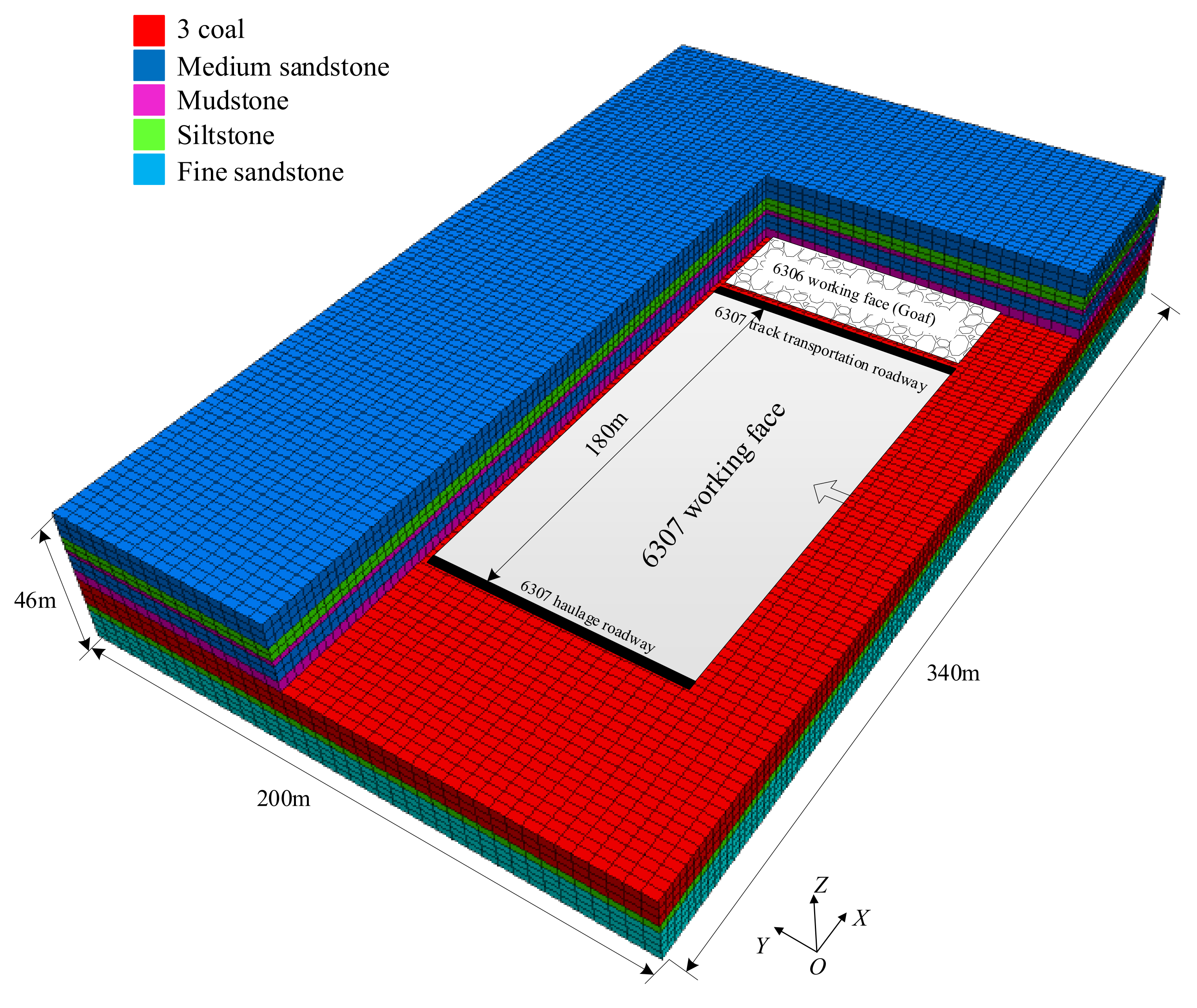
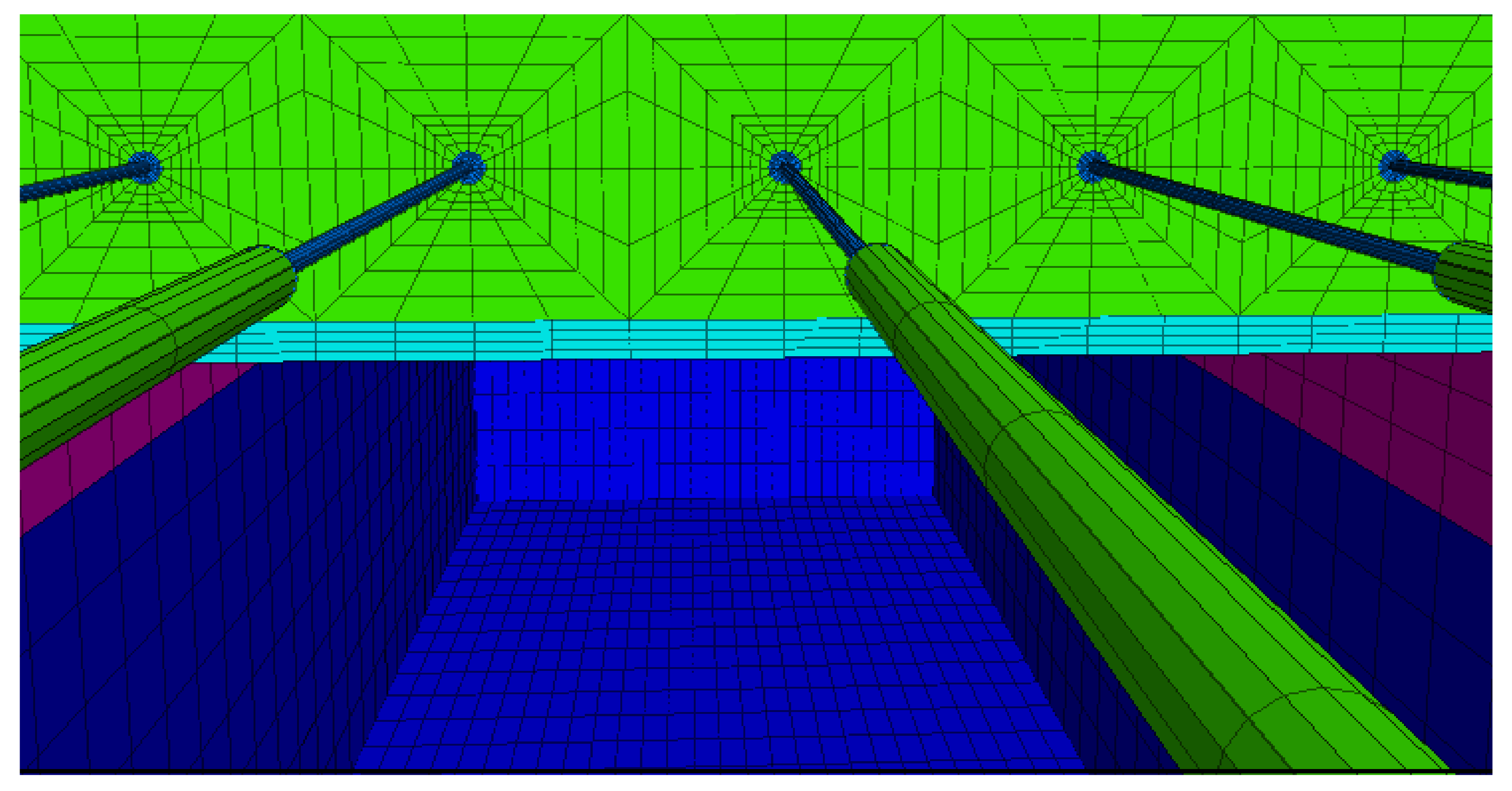
3.1. Numerical Model and Simulation Schemes
Tangkou Coal Mine is located in Nanzhang Town, Jining City, Shandong Province, and the 6307 working face (Figure 6a) of Tangkou coal mine was analyzed in this study. The thickness of coal seam is 8.1 m–10.4 m, and the burial depth of the 6307 working face is approximately 980 m. Fully mechanized top coal caving with strike longwall retreating is used to mine the 6307 working face. The roof and floor strata of the coal seam are composed of relatively complete medium sandstone and siltstone (Figure 6b). The roadway is excavated along the coal seam floor with a section size of 5400 × 3800 mm, and a both anchor, net, and cable supports are used (Figure 6c).
Figure 6.
Diagram of the 6307 working face. ((a) 6307 working face layout plan; (b) 6307 working face top and bottom rock; (c) Diagram of roadway support at 6307 working face).
A FLAC3D numerical model was constructed based on the 6307 working face. The size of the model is 340 m × 200 m × 46 m (Figure 7). Considering the burial depth of the working face, a uniform distribution load of 23 MPa was applied at the top to simulate the weight of overlying strata. Rock type and mechanical parameters were selected based on mine geology reports and laboratory test results (Table 1). The large-diameter borehole was placed to the side of the coal side of the roadway. The mesh around the borehole is shown in Figure 8.
Figure 7.
FLAC3D numerical calculation model.
Table 1.
Physical and mechanical parameters of coal and rock.
Figure 8.
Mesh generation around boreholes.
The effect of diameter of the enlarged-diameter section, length of the enlarged-diameter section, and borehole space on pressure relief effect and roadway deformation was simulated. The simulation scheme is as follows.
- (1).
- Different diameters of enlarged-diameter section
Under the same total borehole length, length of the enlarged-diameter section, diameter of the unenlarged-diameter section, and borehole space, enlarged-diameter sections with diameters of 90 mm, 140 mm, 190 mm, and 240 mm were selected to investigate the pressure relief effect and roadway deformation (Figure 9) (Table 2).
Figure 9.
Diagram of the simulation scheme for enlarged-diameter sections with varying diameters.
Table 2.
Simulation scheme of different diameters of enlarged-diameter section.
- (2).
- Different lengths of the enlarged-diameter section
Under the same total borehole length, diameter of the unenlarged-diameter section, diameter of the enlarged-diameter section, and borehole space, enlarged-diameter sections with lengths of 11 m, 13 m, 15 m, 17 m, and 19 m were selected to investigate the pressure relief effect and roadway deformation (Figure 10) (Table 3).
Figure 10.
Diagram of the simulation scheme for enlarged-diameter sections with varying lengths.
Table 3.
Simulation scheme for enlarged-diameter sections with varying lengths.
- (3).
- Different borehole spaces
Under the same total borehole length, the length of the enlarged-diameter section, the diameter of unenlarged-diameter section, and the diameter of enlarged-diameter section, borehole spaces of 0.8 m, 1.6 m, 2.4 m, and 3.2 m were selected to investigate the pressure relief effect and roadway deformation (Figure 11) (Table 4).
Figure 11.
Diagram of the simulation scheme for different borehole spaces.
Table 4.
Simulation scheme for different boreholes spaces.
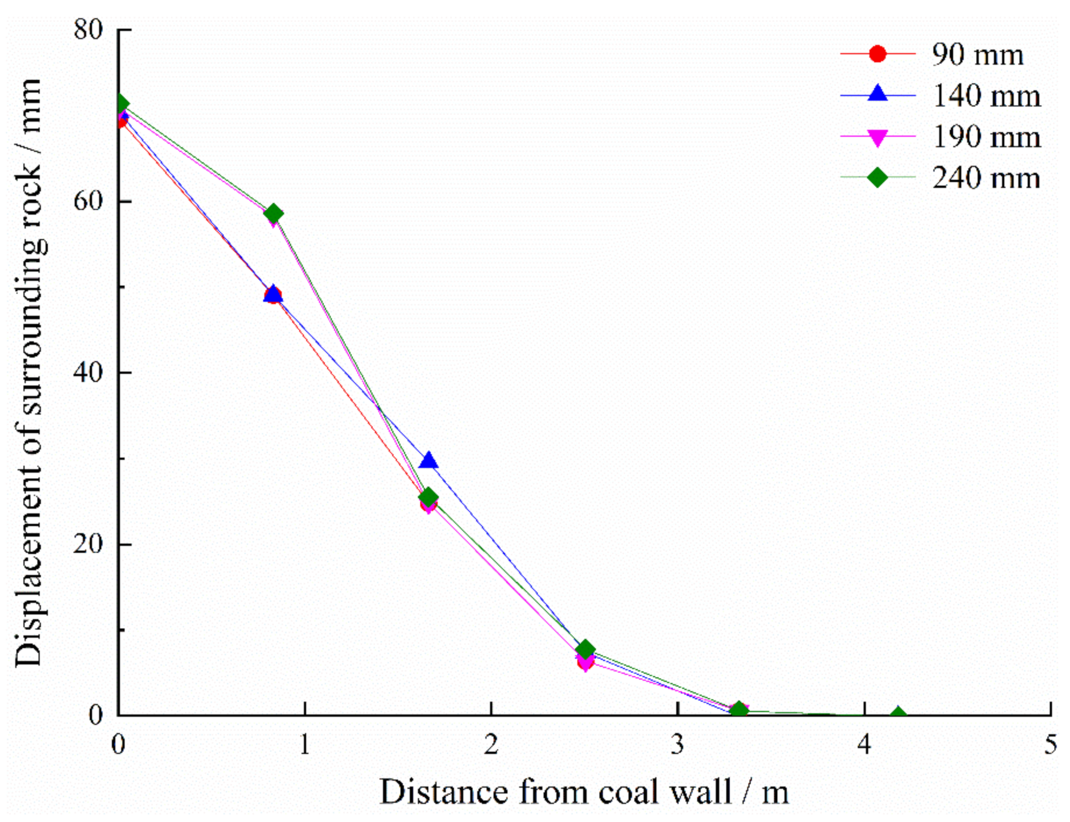
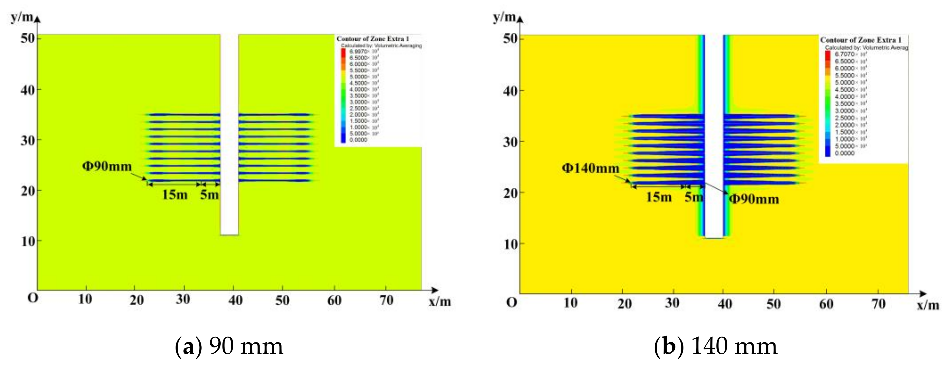
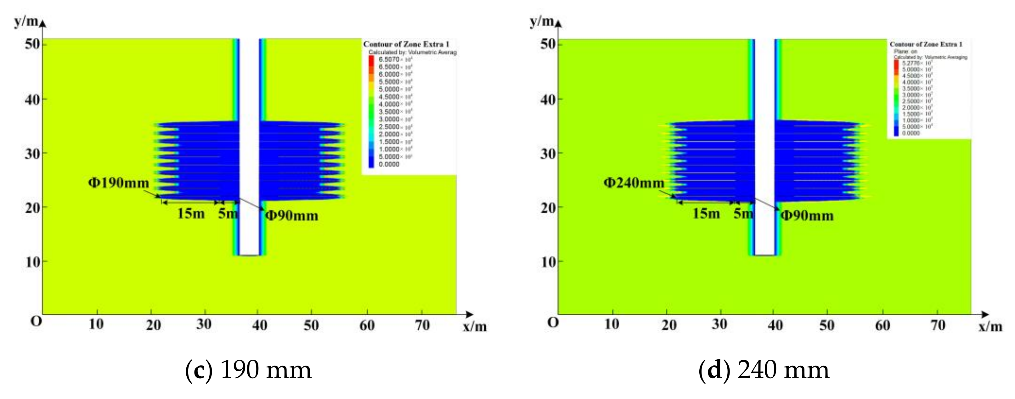
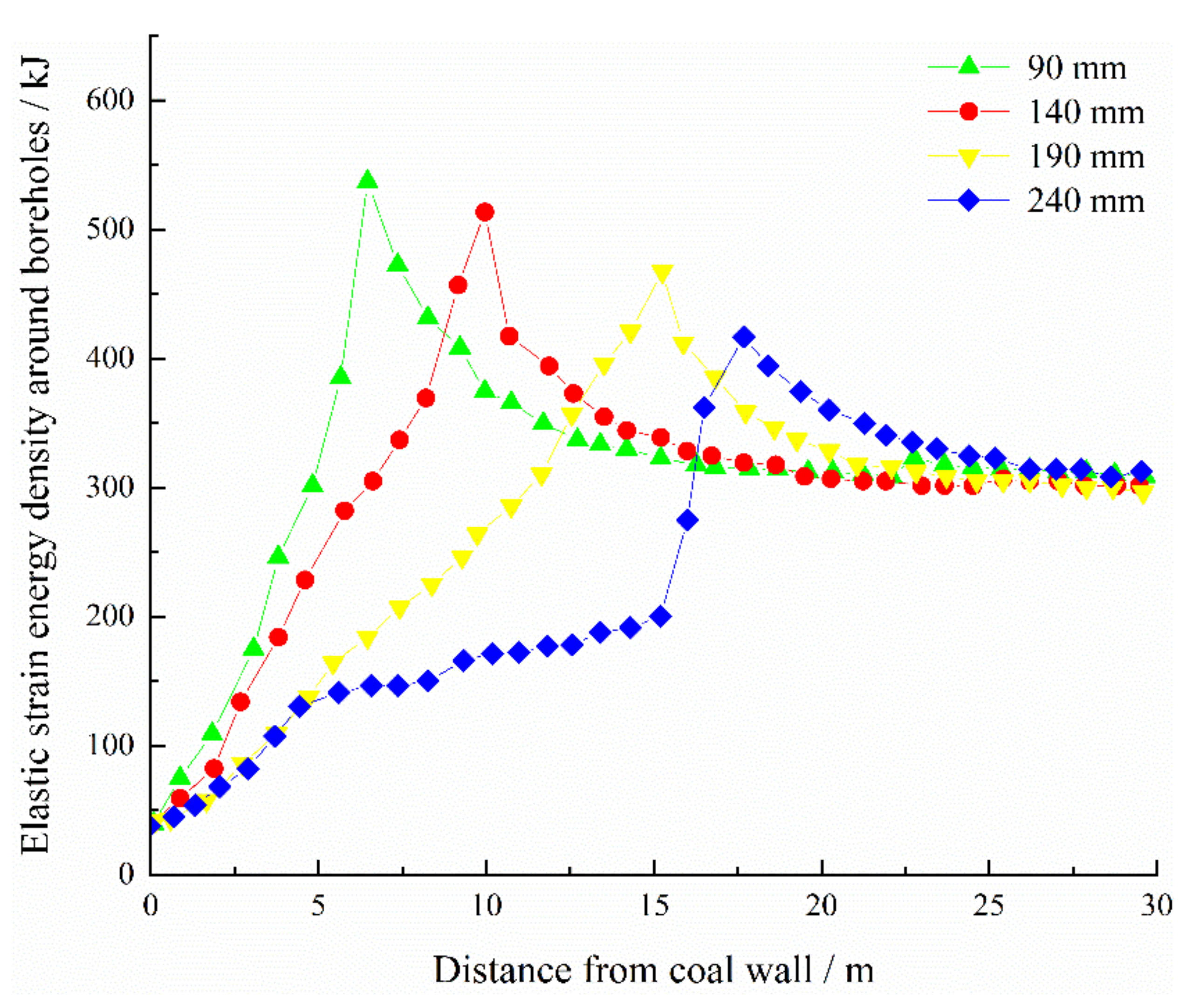
3.2. Effect of Diameter of the Enlarged-Diameter Section on Pressure Relief Effect and Roadway Deformation
Figure 12 and Figure 13 respectively show the distribution maps and curves of elastic strain energy density around boreholes with different diameters of the enlarged-diameter section. With increasing diameter of the enlarged-diameter section, the elastic strain energy density around the borehole gradually decreased (Figure 12). For conventional large-diameter pressure relief boreholes (the diameter of borehole was 90 mm, as shown in Figure 12a), a small low elastic strain energy density zone was observed around a single borehole. When the diameter of the enlarged-diameter section was 190 mm, the low energy zones around borehole expand and overlap (Figure 12c), and the energy peak was 15.3 m away from the coal side (Figure 13). With increasing diameter of the enlarged-diameter section, the energy peak gradually transfered into the deep surrounding rock. When the diameter of the enlarged-diameter section increased to 240 mm, the energy accumulation area was transferred to the end of the borehole (Figure 12d), and the energy peak was about 18.5 m away from the roadway side (Figure 13).

Figure 12.
Distribution maps of elastic strain energy density around boreholes under different diameters of the enlarged-diameter section.
Figure 13.
Distribution curves of elastic strain energy density around boreholes under different diameters of the enlarged-diameter section.
Borehole pressure relief reduces the peak elastic strain energy density of surrounding rock (Figure 13). With increasing diameter of the enlarged-diameter section, the peak elastic strain energy density of the coal body gradually decreases, from 5.3 × 10⁵ J (diameter of enlarged-diameter section was 90 mm) to 4.2 × 10⁵ J (diameter of enlarged-diameter section was 240 mm).
Figure 14 shows the displacement curves of surrounding rocks under the different diameters of the enlarged-diameter section. With increasing the distance from the coal wall, the displacement of the measured points in the surrounding rock gradually decreased (Figure 14). With increasing diameter of enlarged-diameter section, the displacement on both sides of the roadway changed slightly.
Figure 14.
Displacement curves of surrounding rock under different diameters of the enlarged-diameter section.
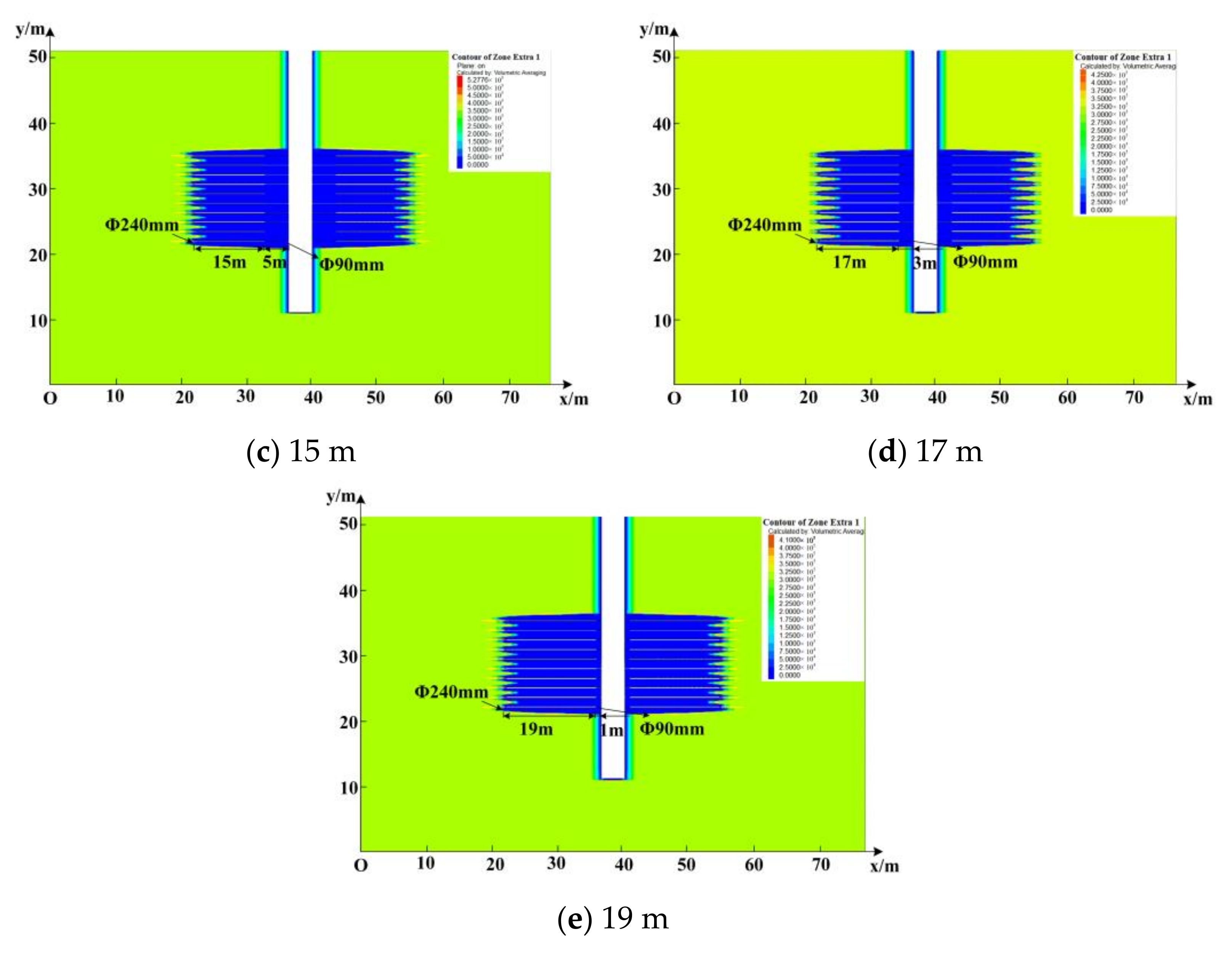
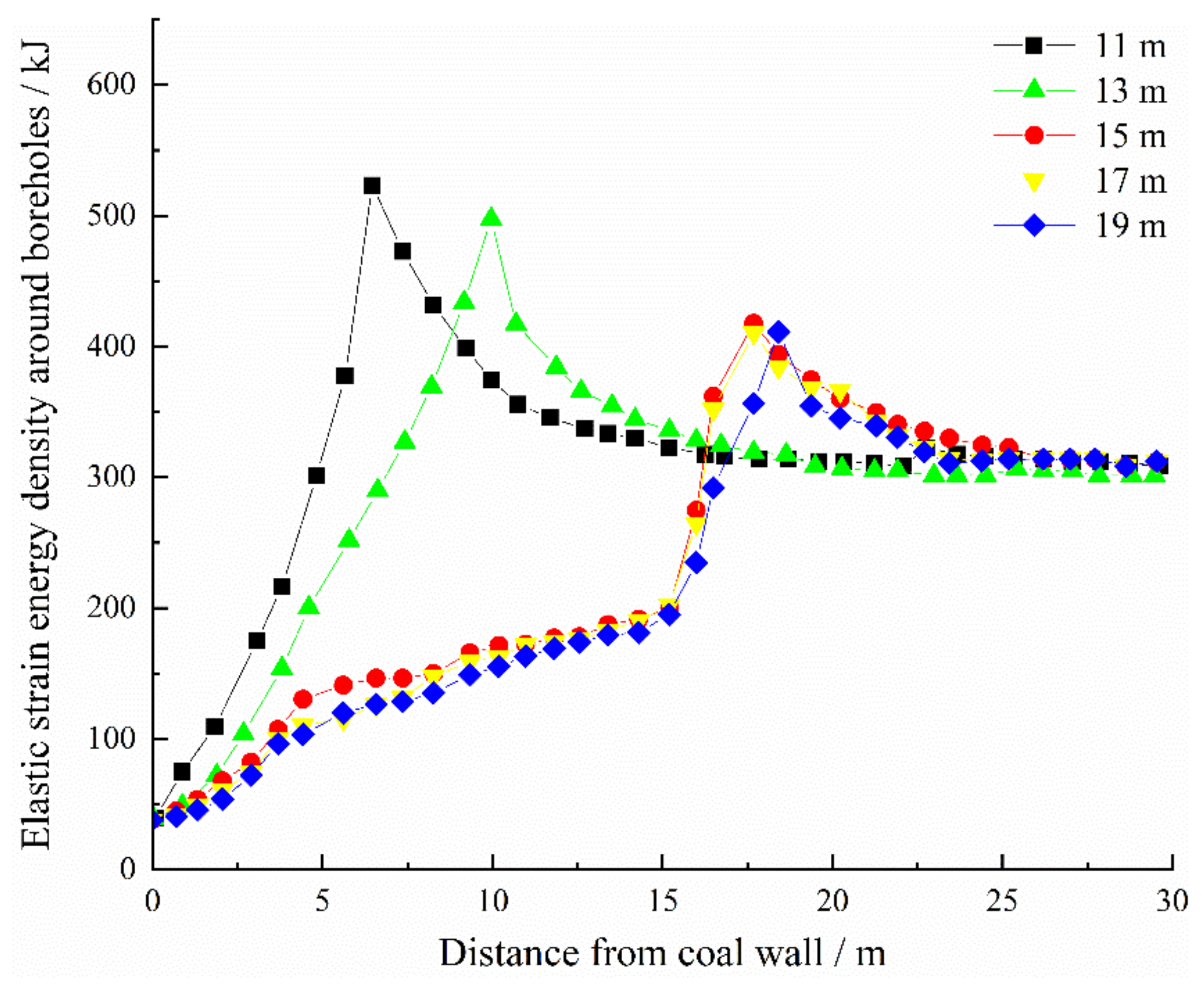
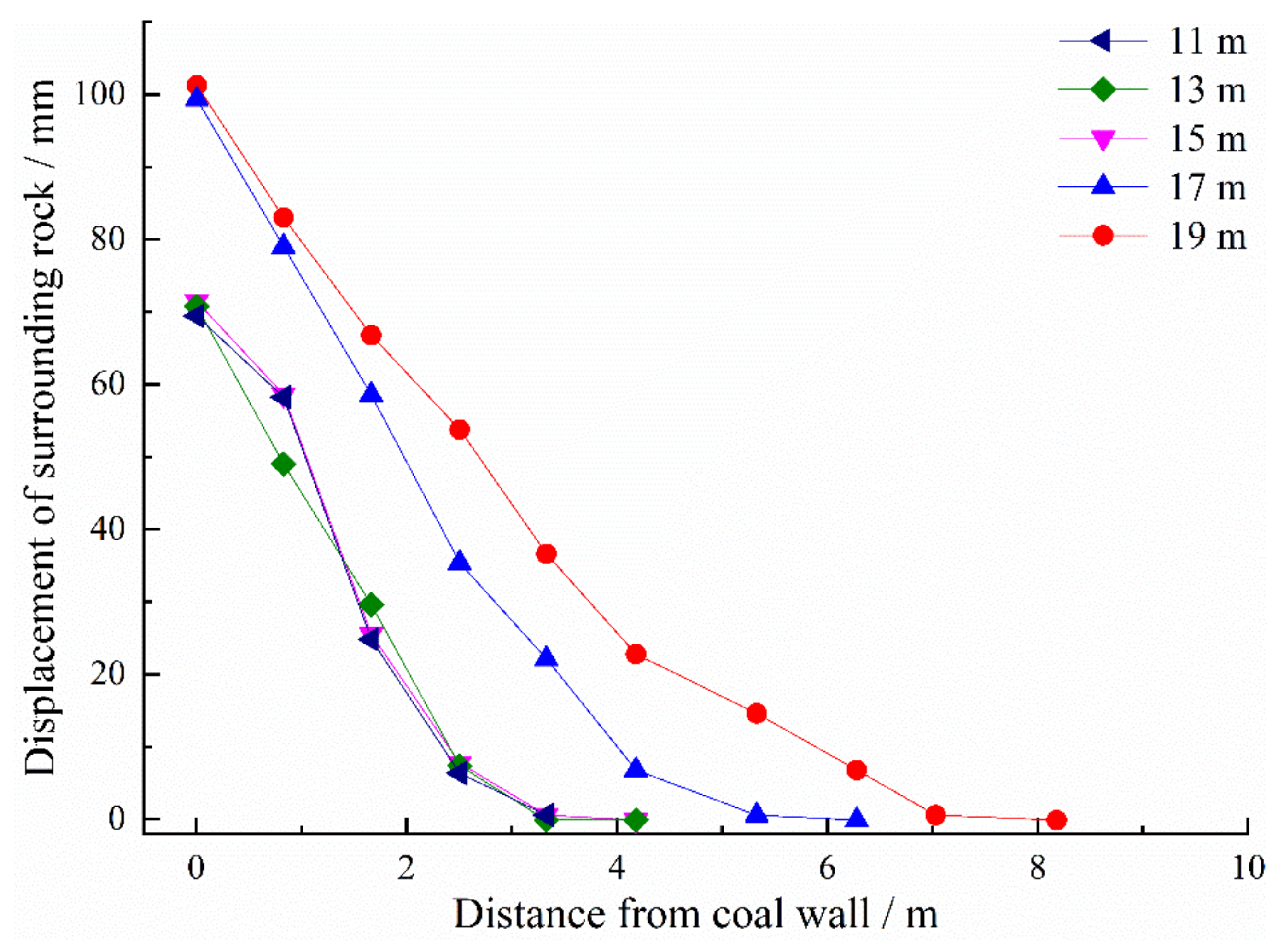
3.3. Effect of Lengths of the Enlarged-Diameter Section on Pressure Relief and Roadway Deformation
Figure 15 and Figure 16 respectively show the distribution maps and curves of elastic strain energy density around boreholes for different lengths of the enlarged-diameter section. The elastic strain energy density around the borehole decreased significantly with increasing the length of the enlarged-diameter section (Figure 15). When the length of the enlarged-diameter section was 15 m, the low elastic energy density zones around the borehole began to overlap (Figure 15c), and the peak strain energy density around borehole decreases from 5.3 × 10⁵ J (the length of the enlarged-diameter section was 11 m) to 4.2 × 10⁵ J (Figure 16). It can be concluded that increasing the length of the enlarged-diameter section can effectively reduce the accumulated energy.

Figure 15.
Distribution maps of elastic strain energy density around boreholes under different lengths of the enlarged-diameter section.
Figure 16.
Distribution curves of elastic strain energy density around boreholes under different lengths of the enlarged-diameter section.
Figure 17 shows the displacement curves of surrounding rocks under different lengths of the enlarged-diameter section. The displacement variation of the two sides of the roadway under the conditions of enlarged-diameter borehole lengths of 11 m, 13 m, and 15 m was similar. When the length of enlarged-diameter section was longer than 15 m (17 m and 19 m, Figure 17), the displacement of the two sides of the roadway (0 m away from the roadway side, Figure 17) increases by 42.9%.
Figure 17.
Displacement curves of surrounding rock under different lengths of the enlarged-diameter section.
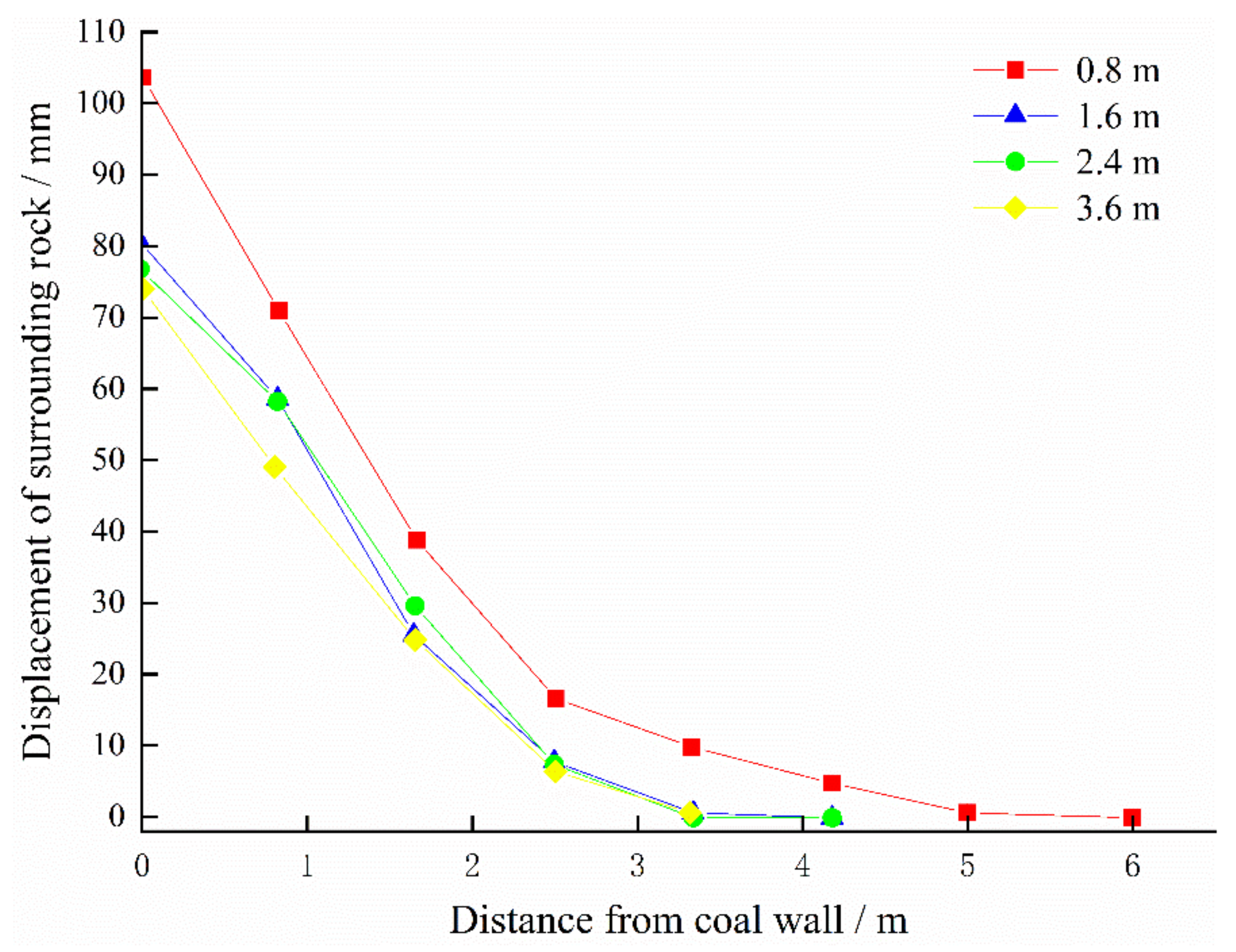
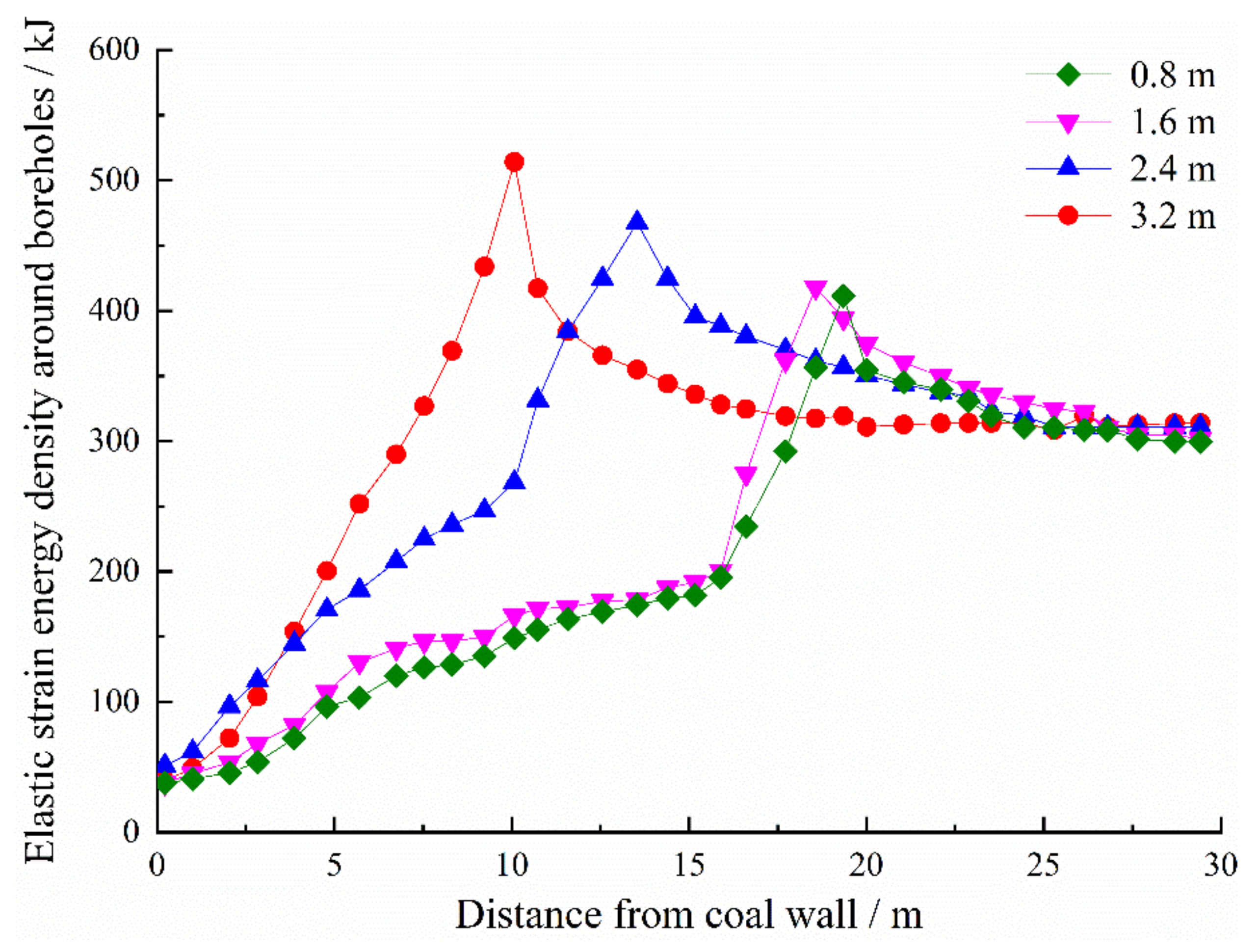
3.4. Effect of Borehole Space on Pressure Relief Effect and Roadway Deformation
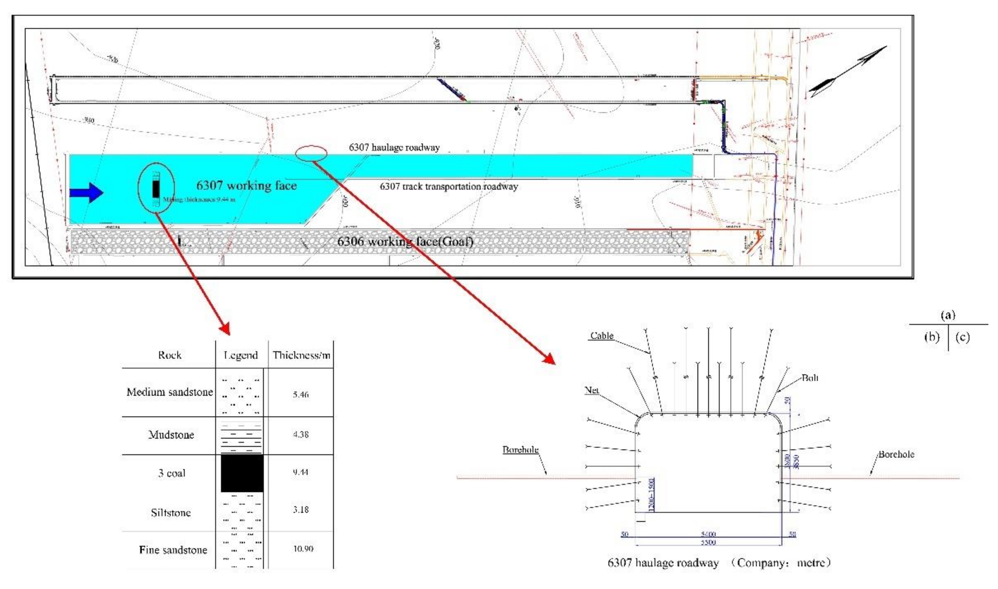
Figure 18 shows the distribution curves of elastic strain energy density around boreholes under different borehole spaces. With decreasing borehole space, the peak strain energy density decreases significantly. When the borehole space was changed from 3.2 m to 0.8 m, the peak elastic strain energy density decreased by 19.6%. The pressure relief effect for a borehole space of 1.6 m and 0.8 m was the same.
Figure 18.
Distribution curves of elastic strain energy density around boreholes under different borehole space.
Figure 19 shows the roadway displacement curves for different borehole spaces. With decreasing borehole space, displacement on both sides of the roadway increases. When the borehole space was 0.8 m, the displacement was 103.3 mm. Compared with a borehole space of 0.8 m, the displacements of surrounding rocks (0 m away from roadway, Figure 19) under a borehole space of 1.6 m, 2.4 m, and 3.2 m decreased by 23.3%, 25.6%, and 28.3%, respectively.
Figure 19.
Displacement curves of roadway under different borehole spaces.
4. Field Test
The burial depth of the 6307 working face in Tangkou coal mine is approximately 980 m. After roadway excavation, a conventional large diameter borehole is constructed on the roadway side. According to the initial design scheme, the pressure relief borehole is 1.2–1.5 m away from the coal seam floor, with a 150 mm diameter, 20 m depth, and 0.8 m space, (Figure 20).
Figure 20.
Diagram of large diameter pressure relief boreholes.
Figure 21 shows the displacement monitoring results of the roadway before and after the borehole pressure relief. At the initial monitoring stage, the deformation of surrounding rock increased significantly and entered the stable stage after 15 days (Figure 21). Before and after pressure relief, the displacement between roof and floor is the same, while the displacement between the two sides of the roadway after pressure relief is 1.8 times that before pressure relief.
Figure 21.
Roadway displacement curves.
Figure 22 shows the stress monitoring results of bolts before and after borehole pressure relief. At the initial stage of monitoring, the bolt stress increased significantly, then remained at a relatively stable value after 15 days (Figure 22). Where no pressure relief borehole were constructed, the stress on the two sides of the roadway stabilized at 70 kN (Figure 22). For the borehole pressure relief zone, the final stress of bolt ②, bolt ①, bolt ④, and bolt ③ is 49 kN, 94 kN, 60 kN, and 105 kN, respectively (Figure 22b), and the stress of the bolt near the borehole pressure relief zone is far less than that far from the pressure relief zone.

Figure 22.
Stress monitoring of bolt.
According to the field monitoring results, the concentrated high stress zone on the roadway side was transferred to the deep area due to borehole pressure relief, which reduces the possibility of rock burst. However, the construction of the pressure relief borehole also damaged the integrity of the surrounding rock and the support system. In some of the pressure relief zones, the bolt was broken. It is expected that the two sides of the roadway experience serious deformation after mining due to the influence of advanced abutment pressure.
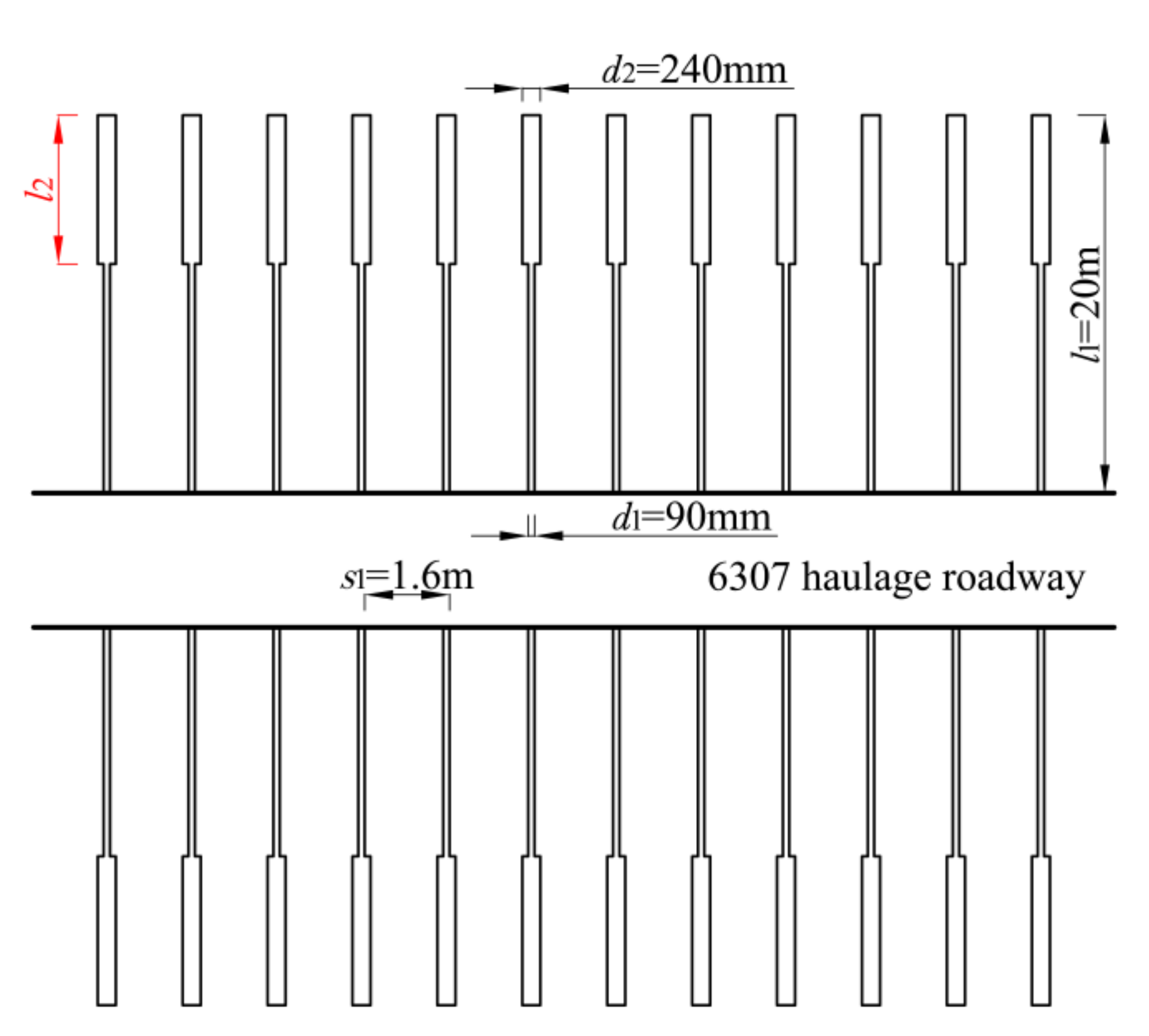
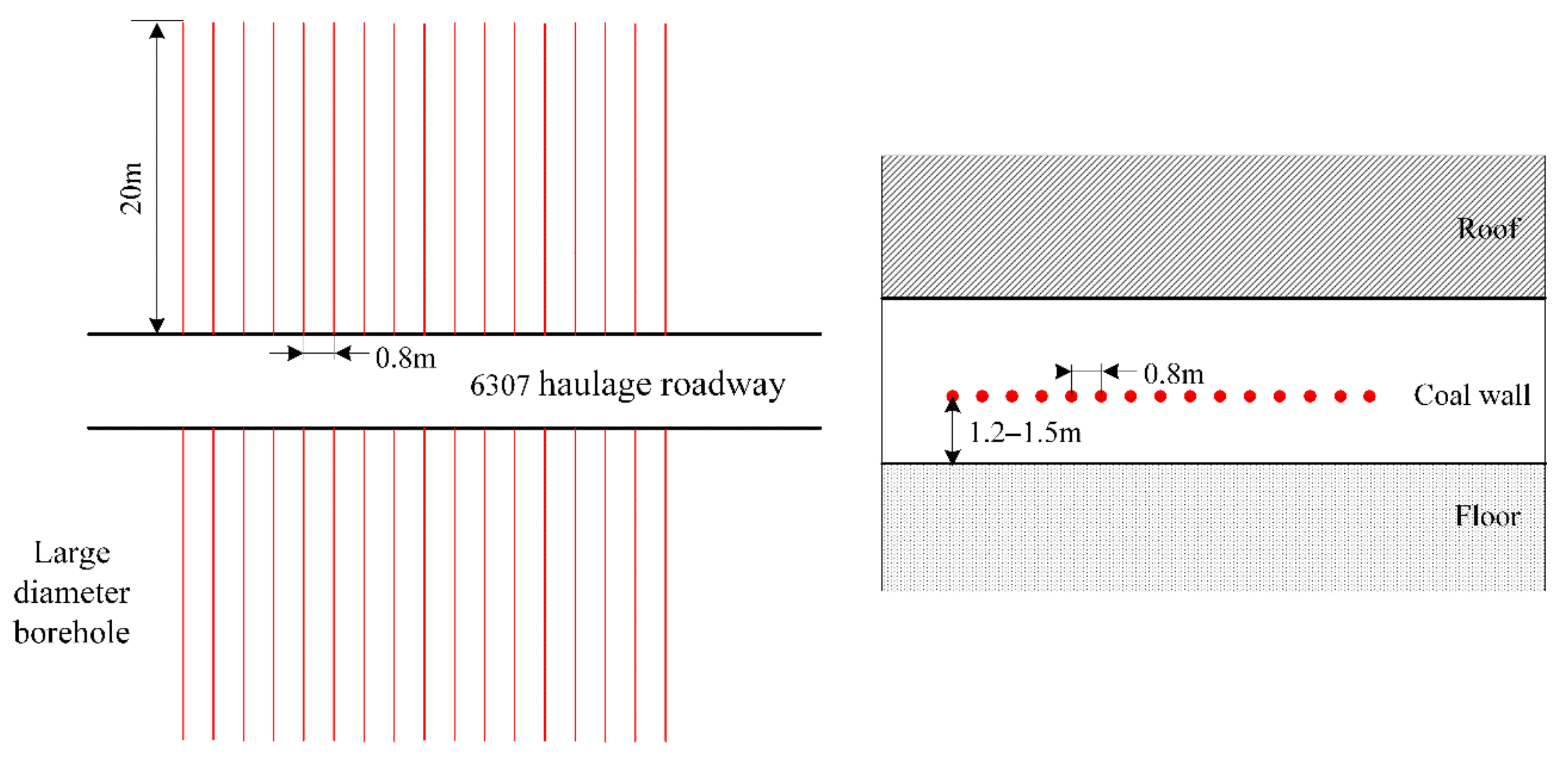
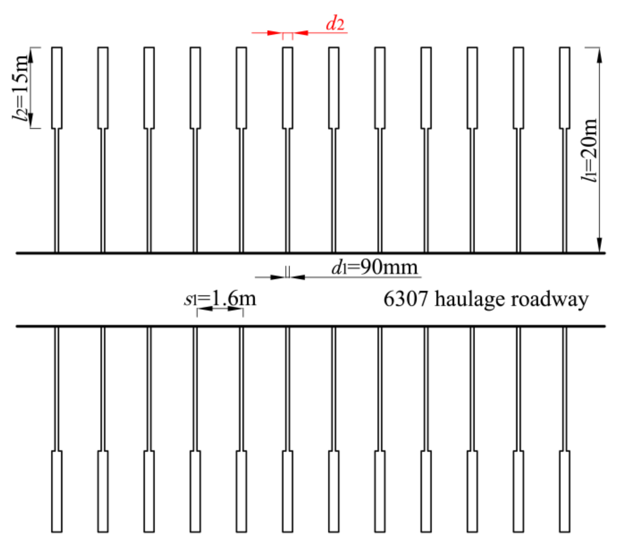
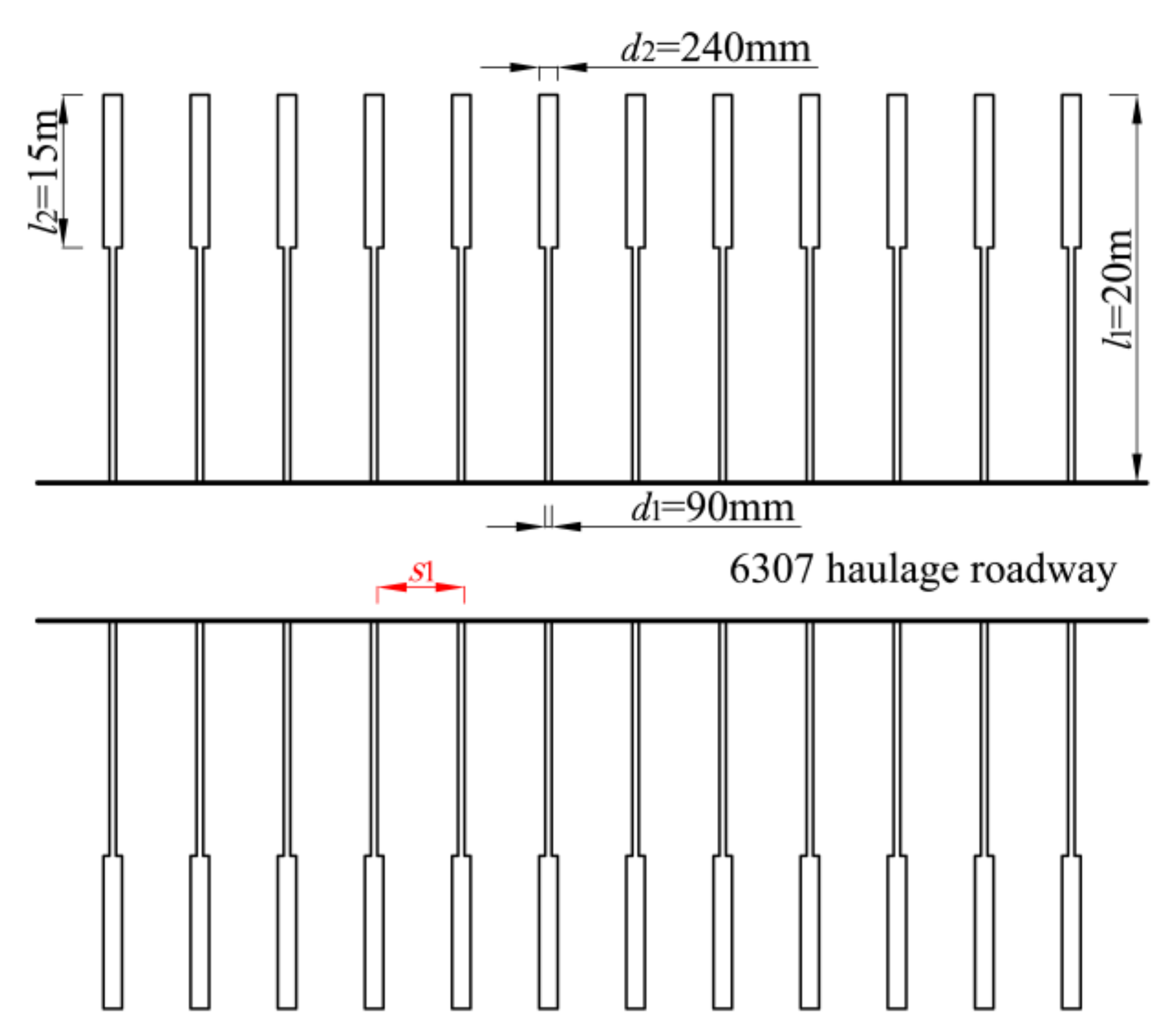
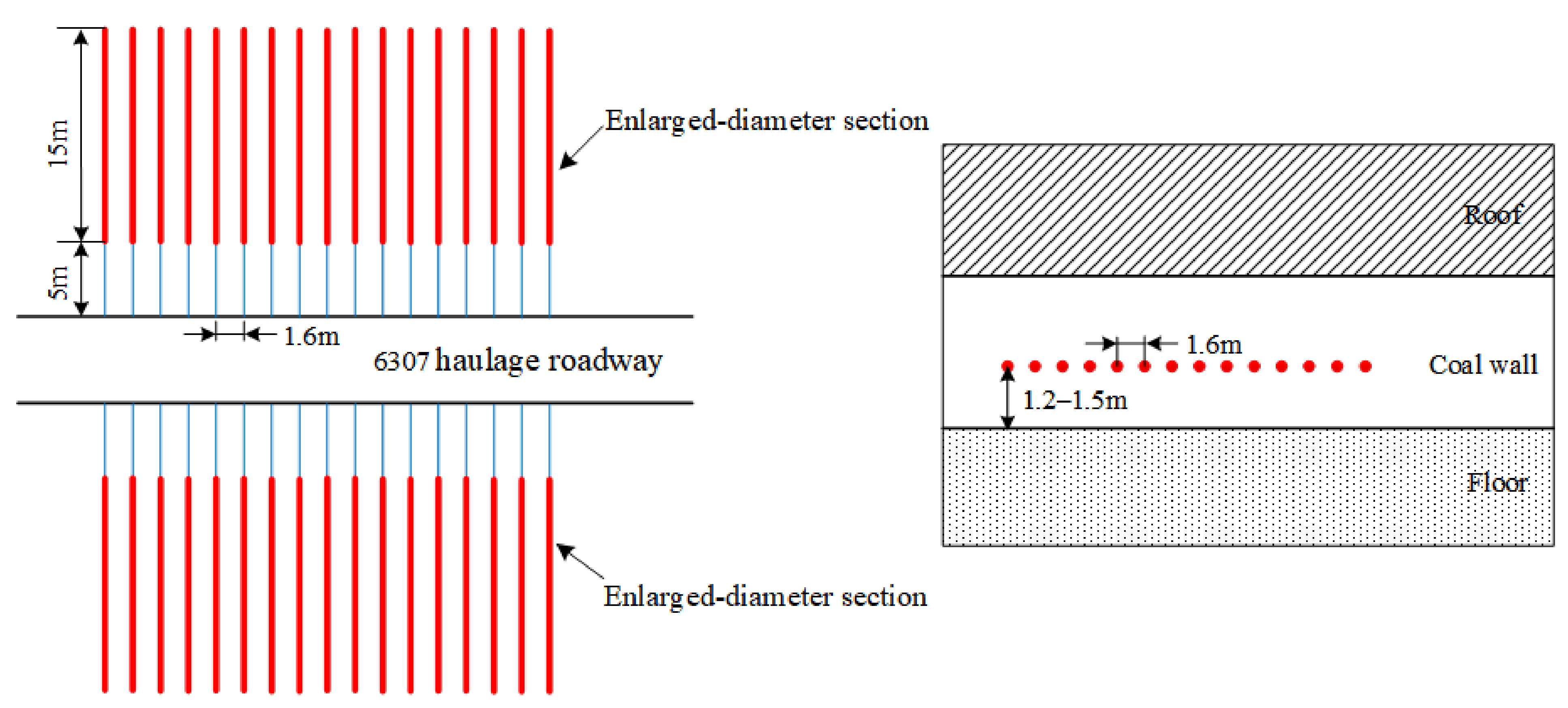
4.1. Key Parameters for Segmented Enlarged-Diameter Borehole
Based on the theoretical and numerical simulation results, the key parameters of segmented enlarged-diameter borehole were designed in a 100 m length roadway in the 6307 working face.
- (1).
- Total borehole lengthReferring to the borehole pressure relief parameters of the adjacent working face of the 6307 working face, the length of the pressure relief borehole of the 6307 working face was determined to be 20 m.
- (2).
- Diameter of the unenlarged-diameter sectionAccording to the simulation results in Section 3.2, when the diameter of the hole in the unenlarged-diameter section was 90 mm, the roadway deformation was relatively small. Thus, the diameter of the borehole in unenlarged-diameter section was determined to be 90 mm.
- (3).
- Diameter of enlarged-diameter sectionAccording to the simulation results in Section 3.2, with increasing diameter of the enlarged-diameter section, the peak elastic strain energy density gradually transfered to the deep surrounding rock of the roadway. The displacement on both sides of the roadway was less affected by the enlarged diameter section. Therefore, the diameter of the enlarged-diameter section was determined to be 240 mm.
- (4).
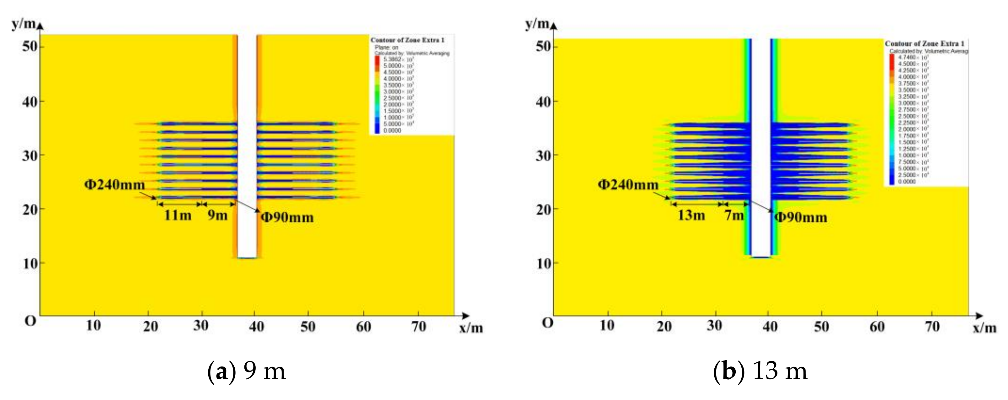
- Length of enlarged-diameter sectionBased on the roadway support design in the 6307 working face, the length of unenlarged-diameter was calculated to be no less than 3.7 m (Equation (14)). According to the simulation results (Section 3.3), it has little influence on the support system when the position of enlarged-diameter section was 5 m away from the roadway side. The length of enlarged-diameter section in roadway of 6307 working face was determined to be 15 m.
- (5).
- Borehole spaceAccording to the simulation results in Section 3.4 (Figure 18), when the space between pressure relief boreholes was less than 1.6 m, the decrease in space will not improve the pressure relief effect. However, it will significantly increase roadway deformation. Considering the construction and safety factors, the space of pressure relief borehole was determined to be 1.6 m. Table 5 and Figure 23 present the key parameters of the segmented enlarged-diameter borehole in the 6307 working face roadway.
Table 5. Key parameters of segmented enlarged-diameter borehole destressing technology.
Figure 23. Diagram of segmented enlarged-diameter borehole.
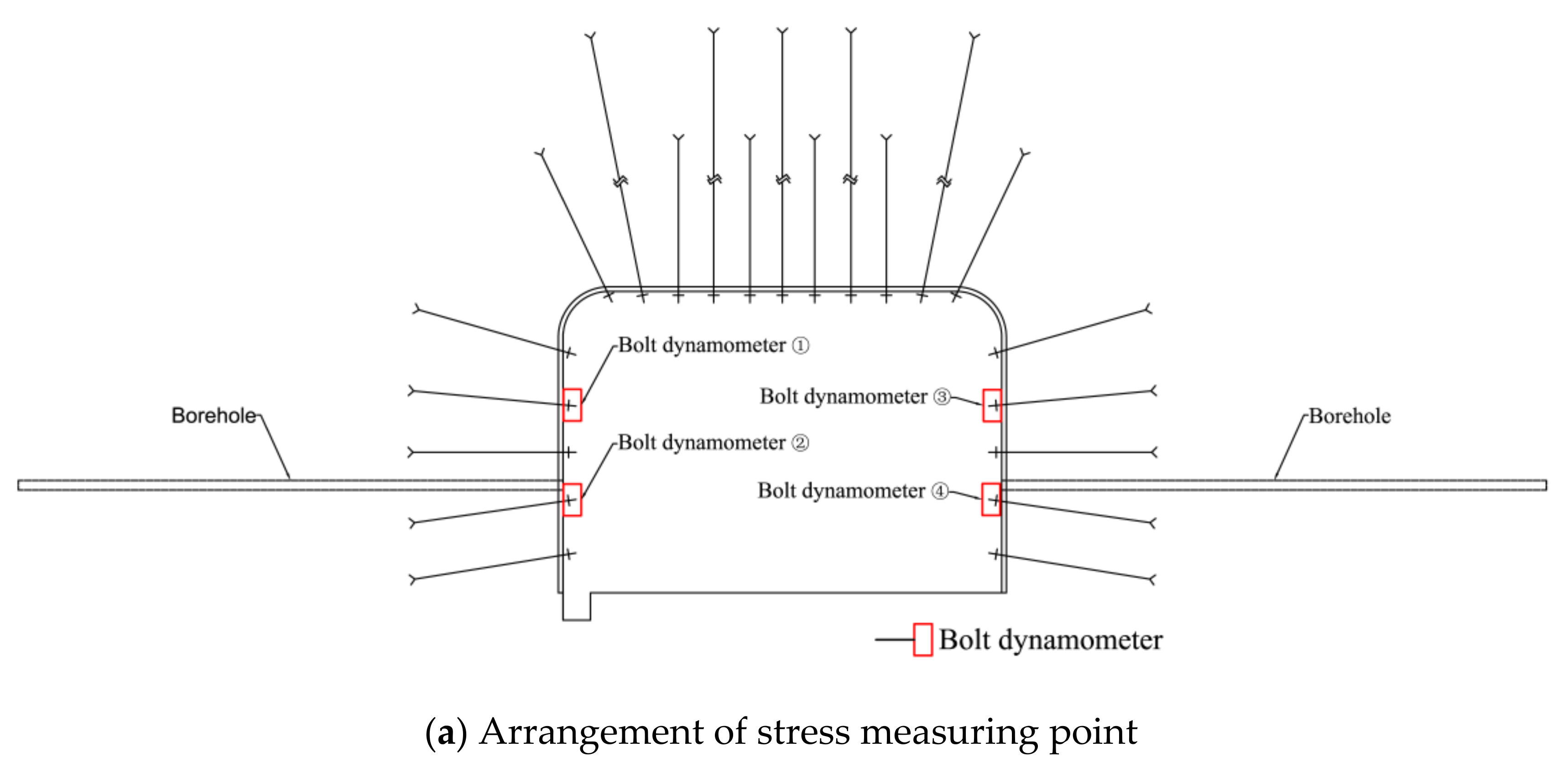
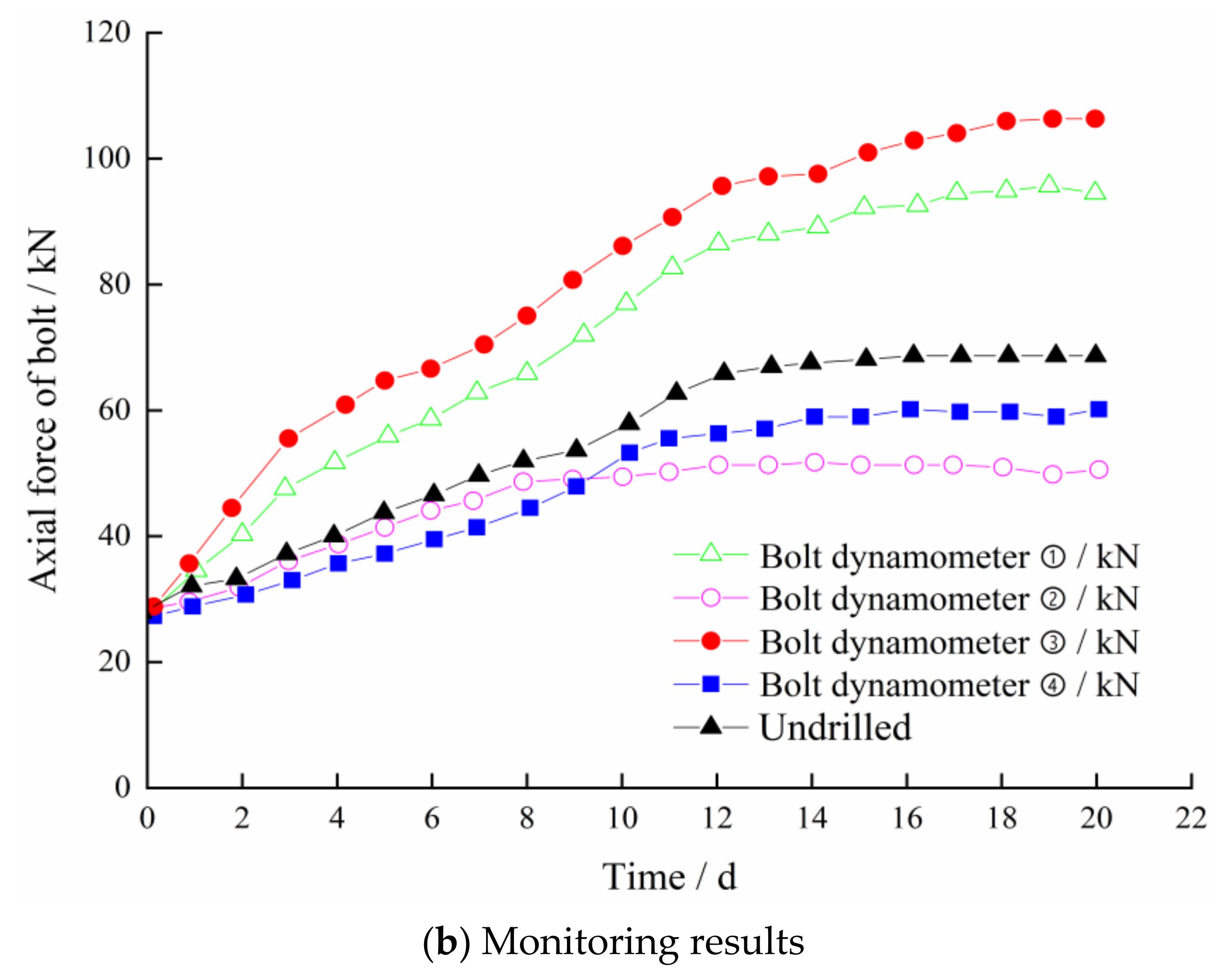
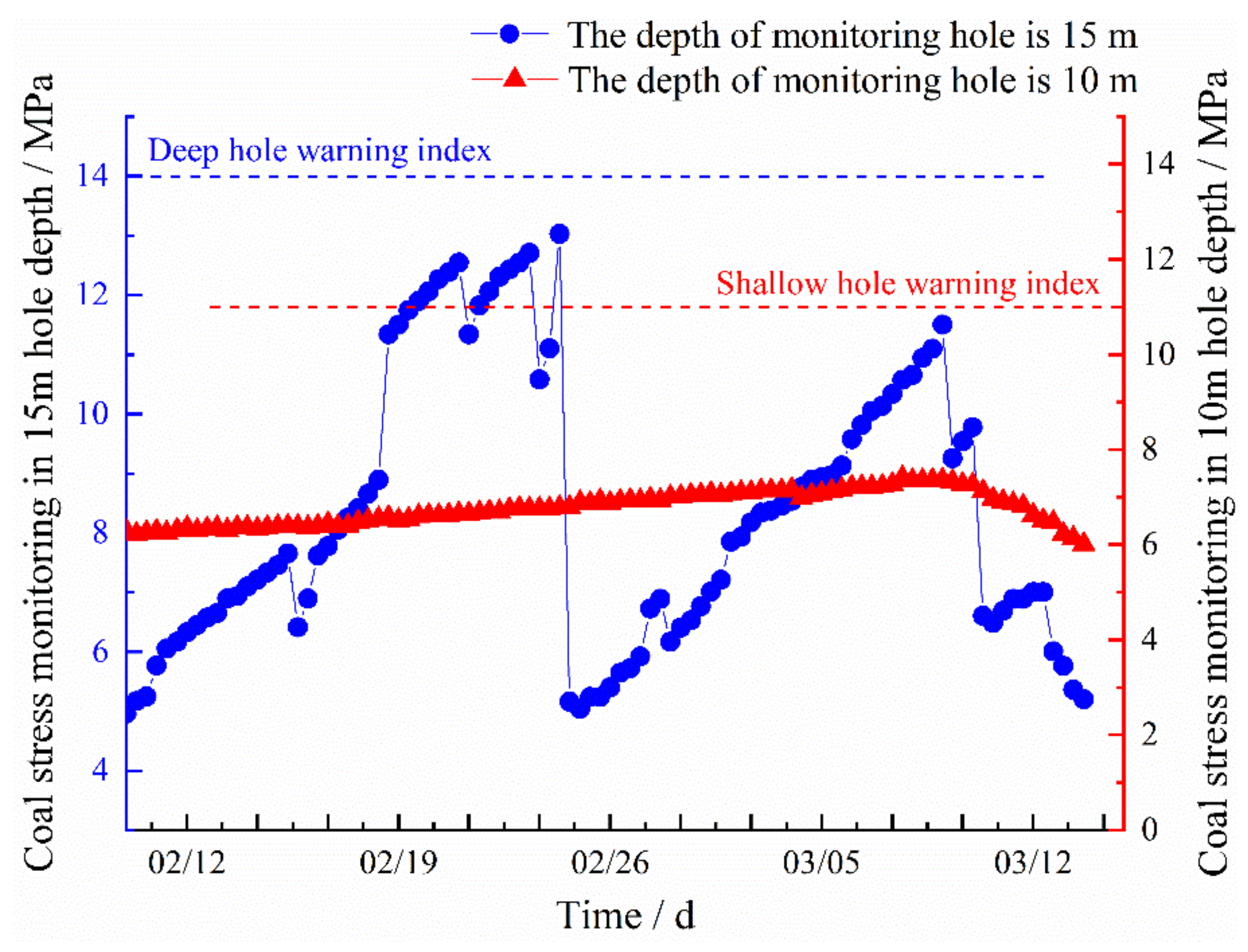
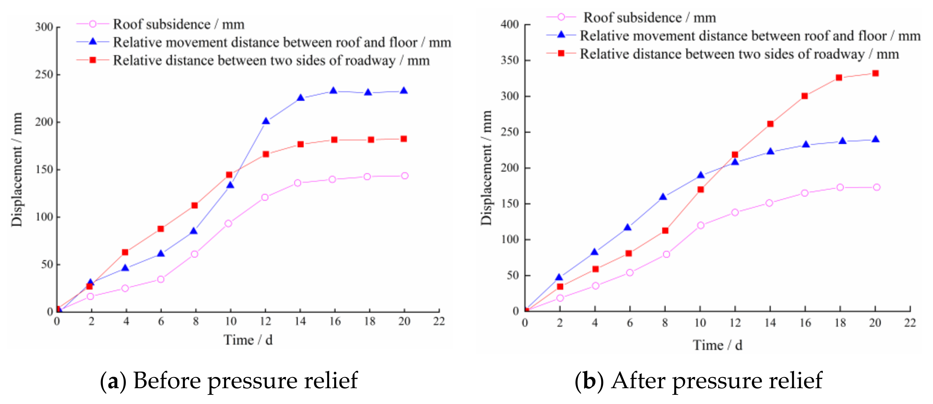
4.2. Pressure Relief Effect Monitoring
4.2.1. Coal Stress Monitoring
Figure 24 shows the coal stress monitoring results obtained using the stress online monitoring system (the stress gauges for the shallow hole and deep hole were arranged between the two segmented enlarged-diameter pressure relief boreholes). The early warning indices are also presented in Figure 24.
Figure 24.
Coal stress monitoring results.
In the initial stage, the stress value of the shallow hole (10 m) was relatively small (6.5 MPa). As the working face continued to advance, the stress gradually increased to 7.4 MPa, which is less than the early warning index (11.0 MPa). For the measuring point in the deep hole (15 m), as the working face advanced, the stress peak first reached 13.0 MPa (the eary warning index was 14.0 MPa) and then dropped to 5.3 MPa, indicating failure of the coal body. The energy accumulated in the coal body was effectively reduced by the segmented enlarged-diameter pressure relief.
4.2.2. Roadway Deformation Monitoring
After the segmented enlarged-diameter borehole pressure relief was implemented, 10 monitoring sections were arranged to monitor the displacement of the roof, floor, and roadway side. The monitoring data were compared with the roadway deformation data in the zone where the conventional large-diameter boreholes pressure relief were implemented (Figure 25).
Figure 25.
Monitoring data of maximum roadway deformation.
Compared with the zone of conventional large-diameter pressure relief, the displacement of the roadway roof, floor, and decreased in the zone of segmented enlarged-diameter borehole pressure relief. The displacement of the roadway side decreased more obviously. The maximum displacement of the roof and floor in the zone of segmented enlarged-diameter borehole pressure relief was about 250 mm, which was 7.5% lower than the zone of conventional large-diameter pressure relief.
For the displacement of the roadway side, the maximum displacement in the zone of conventional large-diameter pressure relief was about 350 mm, while it was only 150 mm in the zone of segmented enlarged-diameter borehole pressure relief, indicating that the segmented enlarged-diameter borehole destressing technology can effectively reduce roadway deformation.
5. Conclusions
In this study, segmented enlarged-diameter borehole destressing technology was investigated and applied the to the 6307 working face of Tangkou Coal mine. The main conclusions are:
- (1).
- According to the theory of elastic-plastic mechanics, the distribution range and influencing factors of the coal pressure relief zone around the borehole are obtained. Furthermore, the minimum length of the unenlarged-diameter section of the borehole was determined.
- (2).
- The effects of diameter of the enlarged-diameter section, length of the enlarged-diameter section, and borehole space on pressure relief and roadway deformation were investigated. The larger the diameter of the enlarged-diameter section, the better the pressure relief effect. With increasing diameter of the enlarged-diameter section, the displacement on both sides of the roadway changed slightly. Increasing the length of the enlarged-diameter section can effectively reduce the energy accumulated around the boreholes and transfer the energy peak to the deep surrounding rock. However, the longer the length of the enlarged-diameter section, the larger the deformation of the surrounding rock. With decreasing borehole space, the peak energy around the boreholes decreased, and the deformation of both sides of the roadway increased significantly.
- (3).
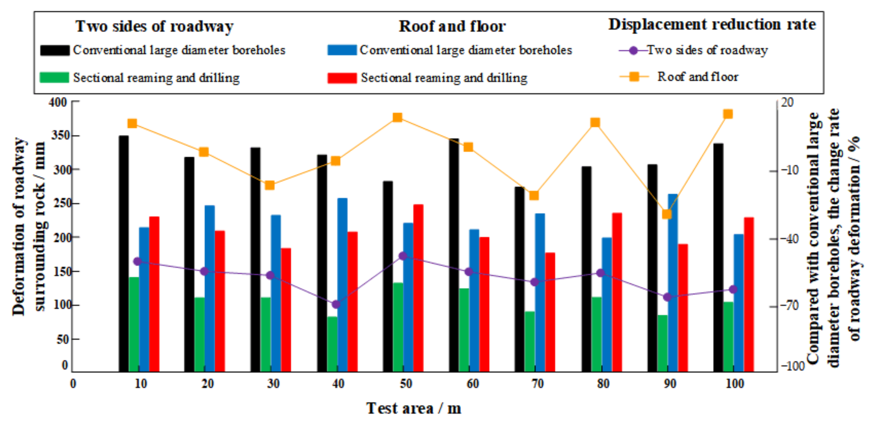
- The key parameters of segmented enlarged-diameter pressure relief borehole were determined for 6307 working face. Field monitoring results showed that the accumulated energy can be effectively reduced using segmented enlarged-diameter pressure relief boreholes, effectively controlling the roadway deformation. Segmented enlarged-diameter pressure relief technology can effectively mitigate the problems of excessive pressure relief (the strength of the surrounding rock was reduced after pressure relief) and insufficient pressure relief (rock burst still occurred after pressure relief) as well as provide a reference for the rock burst prevention and roadway stability control.
Author Contributions
Conceptualization, S.G. and B.J.; methodology, B.J.; software, K.D.; validation, C.C. and K.D.; formal analysis, H.X.; investigation, K.D.; resources, B.J.; data curation, C.C.; writing—original draft preparation, C.C.; writing—review and editing, S.G.; visualization, C.C.; supervision, S.G.; project administration, B.J.; funding acquisition, B.J. All authors have read and agreed to the published version of the manuscript.
Funding
This research is founded by the Natural Science Foundation of China (52004144) and Natural Science Foundation of Shandong Province, China (ZR2019BEE001).
Institutional Review Board Statement
Not applicable.
Informed Consent Statement
Not applicable.
Data Availability Statement
Not applicable.
Conflicts of Interest
The authors declare no conflict of interest.
References
- Kang, H.; Fan, M.; Gao, F.; Zhang, H. Deformation and support of rock roadway at depth more than 1000 m. Chin. J. Rock Mech. Eng. 2015, 34, 2227–2241. [Google Scholar]
- Feng, Q.; Jin, J.; Zhang, S. Study on a Damage Model and Uniaxial Compression Simulation Method of Frozen–Thawed Rock. Rock Mech. Rock Eng. 2022, 55, 187–211. [Google Scholar] [CrossRef]
- Li, W.S.; Jiang, B.Y.; Gu, S.T.; Yang, X.X.; Shaikh Faiz, U.A. Experimental study on the shear behaviour of grout-infilled specimens andmicromechanical properties of grout-rock interface. J. Cent. South Univ. 2021, 29, 1–14. [Google Scholar]
- Sun, S.; He, P.; Wang, G.; Li, W.; Wang, H.; Chen, D.; Xu, F. Shape characterization methods of irregular cavity using Fourier analysis in tunnel. Math. Comput. Simul. 2021, 187, 191–214. [Google Scholar] [CrossRef]
- Zhang, C.; Zhao, Y.X.; Bai, Q.S. 3D DEM method for compaction and breakage characteristics simulation of broken rock mass in goaf. Acta Geotech. 2021. [Google Scholar] [CrossRef]
- Zhang, C.; Bai, Q.S.; Chen, Y.H. Using stress path-dependent permeability law to evaluate permeability enhancement and coalbed methane flow in protected coal seam: A case study. Geomech. Geophys. Geo-Energy Geo-Resour. 2020, 6, 53. [Google Scholar] [CrossRef]
- Khan, N.M.; Ahmad, M.; Cao, K.; Ali, I.; Liu, W.; Rehman, H.; Hussain, S.; Rehman, F.U.; Ahmed, T. Developing a New Bursting Liability Index Based on Energy Evolution for Coal under Different Loading Rates. Sustainability 2022, 14, 1572. [Google Scholar] [CrossRef]
- Qi, Q.; Li, Y.; Zhao, S.; Zhang, N.; Zheng, W.; Li, H.; Li, H. Seventy years development of coal mine rockburst in China: Establishment and consideration of theory and technology system. Coal Sci. Technol. 2019, 47, 1–40. [Google Scholar] [CrossRef]
- Tu, W.F.; Li, L.P.; Zhou, Z.Q.; Shang, C.S. Thickness calculation of accumulative damaged zone by rock mass blasting based on Hoek-Brown failure criterion. Int. J. Geomech. 2022, 22, 04021273. [Google Scholar] [CrossRef]
- Wang, S.; Li, L.P.; Cheng, S.; Yang, J.Y.; Jin, H.; Gao, S.; Wen, T. Study on an improved real-time monitoring and fusion prewarning method of water inrush in tunnels. Tunn. Undergr. Space Technol. 2021, 112, 103884. [Google Scholar] [CrossRef]
- Wang, J.; Yang, J.X.; Wu, F.F.; Hu, T.F.; Shams, F.A. Analysis of fracture mechanism for surrounding rock hole based on water-filled blasting. Int. J. Coal Sci. Technol. 2020, 7, 704–713. [Google Scholar] [CrossRef]
- Dou, L.T.; Yang, K.; Chi, X.L. Fracture behavior and acoustic emission characteristics of sandstone samples with inclined precracks. Int. J. Coal Sci. Technol. 2021, 8, 77–87. [Google Scholar] [CrossRef]
- Sousa, L.R.E.; Miranda, T.; Sousa, R.L.E.; Tinoco, J. The Use of Data Mining Techniques in Rockburst Risk Assessment. Engineering 2017, 3, 552–558. [Google Scholar] [CrossRef]
- Ahmad, M.; Hu, J.-L.; Hadzima-Nyarko, M.; Ahmad, F.; Tang, X.-W.; Rahman, Z.U.; Nawaz, A.; Abrar, M. Rockburst Hazard Prediction in Underground Projects Using Two Intelligent Classification Techniques: A Comparative Study. Symmetry 2021, 13, 632. [Google Scholar] [CrossRef]
- Sepehri, M.; Apel, D.B.; Adeeb, S.; Leveille, P.; Hall, R.A. Evaluation of mining-induced energy and rockburst prediction at a diamond mine in Canada using a full 3D elastoplastic finite element model. Eng. Geol. 2020, 266, 105457. [Google Scholar] [CrossRef]
- Aguado, M.B.D.; González, C. Influence of the stress state in a coal bump-prone deep coalbed: A case study. Int. J. Rock Mech. Min. Sci. 2009, 46, 333–345. [Google Scholar] [CrossRef]
- Mazaira, A.; Konicek, P. Intense rockburst impacts in deep underground construction and their prevention. Can. Geotech. J. 2015, 52, 1426–1439. [Google Scholar] [CrossRef]
- Nazimko, V.; Zakharova, L.; Kusen, A.; Peng, S. Rock pressure relief is the basic alternative for sustainable underground mining. E3S Web Conf. 2021, 280, 08020. [Google Scholar] [CrossRef]
- Tan, Y.; Guo, W.; Xin, H.; Zhao, T.; Yu, F.; Liu, X. Key technology of rock burst monitoring and control in deep coal mining. J. China Coal Soc. 2019, 44, 160–172. [Google Scholar] [CrossRef]
- Dou, L.; Lu, C.; Mou, Z.; Qin, Y.; Yao, J. Intensity weakening theory for rockburst and its application. J. China Coal Soc. 2005, 30, 690–694. [Google Scholar]
- Małkowski, P.; Niedbalski, Z. A comprehensive geomechanical method for the assessment of rockburst hazards in underground mining. Int. J. Min. Sci. Technol. 2020, 30, 345–355. [Google Scholar] [CrossRef]
- Konicek, P.; Schreiber, J. Rockburst prevention via destress blasting of competent roof rocks in hard coal longwall mining. J. South Afr. Inst. Min. Metall. 2018, 118, 235–242. [Google Scholar] [CrossRef] [Green Version]
- Salimzadeh, S.; Usui, T.; Paluszny, A.; Zimmerman, R.W. Finite element simulations of interactions between multiple hydraulic fractures in a poroelastic rock. Int. J. Rock Mech. Min. Sci. 2017, 99, 9–20. [Google Scholar] [CrossRef] [Green Version]
- Zhu, S.; Jiang, F.; Shi, X.; Sun, G.; Zhang, Z.; Cheng, X.; Zhang, H. Energy dissipation index method for determining rockburst prevention drilling parameters. Rock Soil Mech. 2015, 36, 2270–2276. [Google Scholar] [CrossRef]
- Jia, C.; Jiang, Y.; Zhang, X.; Wang, D.; Luan, H.; Wang, C. Laboratory and numerical experiments on pressure relief mechanism of large-diameter boreholes. Chin. J. Geotech. Eng. 2017, 39, 1115–1122. [Google Scholar]
- Zhang, S.; Li, Y.; Shen, B.; Sun, X.; Gao, L. Effective evaluation of pressure relief drilling for reducing rock bursts and its application in underground coal mines. Int. J. Rock Mech. Min. Sci. 2019, 114, 7–16. [Google Scholar] [CrossRef]
- Tan, Y.; Guo, W.; Zhao, T.; Meng, X. Coal rib burst mechanism in deep roadway and“stress relief—Support reinforcement”synergetic control and prevention. J. China Coal Soc. 2020, 45, 66–81. [Google Scholar] [CrossRef]
- Yao, J.; Yin, Y.; Zhao, T.; Ren, W.; Qiu, Y.; Guo, W. Segmented enlarged-diameter borehole destressing mechanism and its influence on anchorage support system. Energy Sci. Eng. 2020, 8, 2831–2840. [Google Scholar] [CrossRef]
- Kirsch, C. Die theorie der elastizitat und die bedurfnisse der festigkeitslehre. Z. Des. Ver. Dtsch. Ing. 1898, 42, 797–807. [Google Scholar]
- Jaeger, J.C.; Cook, N.G.; Zimmerman, R. Fundamentals of Rock Mechanics; John Wiley & Sons: Hoboken, NJ, USA, 2009. [Google Scholar]
- Yu, Y.; Wang, D.; Li, Q.; Song, L.; Zhang, C. Elastic-plastic-brittle constitutive model of rocks and its numerical validation. J. China Coal Soc. 2012, 37, 585–589. [Google Scholar] [CrossRef]
- Luo, S.; Wu, Y.; Zhang, J. Rheology control mechanism of surrounding rock mass and anchorage body and its support design optimization. Rock Soil Mech. 2017, 38, 124–132. [Google Scholar] [CrossRef]
- Ma, N.; Li, J.; Zhao, Z. Distribution of the deviatoric stress field and plastic zone in circular roadway surrounding rock. J. China Univ. Min. Technol. 2015, 44, 206–213. [Google Scholar] [CrossRef]
- Hou, G.; Li, J. Analysis of complete process of interaction of surrounding rock and support under elastioplastic deformation condition. Rock Soil Mech. 2012, 33, 961–970. [Google Scholar] [CrossRef]
Publisher’s Note: MDPI stays neutral with regard to jurisdictional claims in published maps and institutional affiliations. |
© 2022 by the authors. Licensee MDPI, Basel, Switzerland. This article is an open access article distributed under the terms and conditions of the Creative Commons Attribution (CC BY) license (https://creativecommons.org/licenses/by/4.0/).


