Article

Determination of Narrow Coal Pillar Width and Roadway Surrounding Rock Support Technology in Gob Driving Roadway

1
School of Mines, China University of Mining and Technology, Xuzhou 221116, China
2
Huaneng Lingtai ShaoZhai Coal Industry Co., Ltd., Pingliang 744400, China
*
Authors to whom correspondence should be addressed.
Sustainability 2022, 14(8), 4848; https://doi.org/10.3390/su14084848
Submission received: 14 February 2022 / Revised: 2 April 2022 / Accepted: 16 April 2022 / Published: 18 April 2022

Abstract

:
In order to determine the rational width of coal pillars and study the surrounding rock control technology of gob side entry driving with a narrow coal pillar, this paper first calculates the width of narrow coal pillar according to limit equilibrium theory; after that, the lateral support pressure and plastic zone development of the goaf is analyzed by numerical simulation to determine the rational width of reserved coal pillar; finally, through the ring breaking deformation regulation of surrounding rock of the gob side entry, the deformation and failure characteristics of the gob-side roadway during excavation and the influence of mining on the deformation and failure of the gob-side roadway are analyzed. The research results show that, combined with theoretical analysis and numerical simulation, the width of narrow coal pillar is decided to be 10 m; the deformation of the coal pillar side of the gob side roadway is much bigger than the roof subsidence, the deformation of the solid coal wall and the floor deformation; after the bolt support design of the gob side roadway, the deformation and damage of the gob side roadway during the driving period is small; during mining, the deformation of the narrow coal pillar wall is the key factor to determine the stability of the gob roadway; under the bolt support scheme, the overall deformation and failure of surrounding rock of the goaf roadway is small, and the control effect of the surrounding rock of the goaf roadway is good.

1. Introduction

As a technology of roadway layout, gob driving has been widely used [1]. However, due to the key curved triangular block structure formed in the basic top rock layer at the goaf edge in the upper section of the working face [2], there are stress reducing areas, rising areas and in-situ stress areas in the coal body near the goaf. So as to reduce the stress of surrounding rock and ensure roadway safety [3], the roadway should be arranged in the stress reduction area of the coal wall [4]. In this case, the roadway and the coal pillar are the most stable. Therefore, the width of the coal pillar for roadway protection should be as small as possible [4], so as to improve the recovery rate of coal and the mining efficiency of the coal mine [4]. If the coal pillar is extremely narrow, it is easy for the coal pillar to deform and break quickly after opening, so that the anchor is installed in the broken surrounding rock, which weakens the anchoring force and reduces the supporting effect of the anchor [5,6]. Many scholars have done research on the technology of Retaining Roadway along the air: Wang Weijun [7] used damage mechanics theory to research the stability of roadway pillars. The results show that the main factor affecting the stability of goaf roadway is high abutment pressure; Zhang Nong [8] analyzed the internal relationship between the mining influence of working face and the deformation and instability of roadway pillars, and put forward the pre-tension anchor belt mesh support technology; Bai Jianbiao et al. [9] studied the relationship between the width and the stability of coal pillars, and claims that high-strength bolts can improve the stability of narrow coal pillars. Zhang Kai and Lu Shuaifeng and Li Jianghao studied the rational width of a narrow coal pillar driven along gob [10,11,12]. Yu Jiaqi et al. [13,14] studied the stability and surrounding rock control technology of side narrow coal pillar in the goaf of a fully mechanized caving face. Zhi Qiang et al. [15,16] researched narrow coal pillar width of gob side entry driving in high stress soft rock gently inclined coal seams. Li Jianjun et al., studied stress and the surrounding rock deformation law of narrow coal pillar in gob side entry driving [3,17]. Chen Jianhang analyzed and researched the axial performance of fully sealed bolt [18,19]. Chang Qingliang studied the width of filling body in gob-side entry retaining with high-water materials [20,21]. Chen Xiaoxiang et al. studied the influencing factors of coal pillar width and put forward the asymmetric support scheme [22,23,24,25].
Taking the Yangjiacun coal mine of Inner Mongolia Shuangxin Mining Co., Ltd. as the background, the paper studies the width of retaining coal pillars and analyzes, under the effect of lateral abutment pressure in upper goaf, the stability of surrounding rock in goaf excavation with narrow coal pillars [24].

2. Project Overview

Yangjiacun mine field of Inner Mongolia Shuangxin Mining Co., Ltd. is located in Ordos City, Inner Mongolia Autonomous Region [4]. There are as many as 25 coal seams in the mine field, with a total thickness of 8.89–34.43 m, with an average of 23.46 m. There are 8 main minable coal seams and 3 secondary minable coal seams. According to the coal seam, the 11 coal seams in the whole minefield are divided into 11 mining areas, which are divided into 2 horizontal development areas. The first horizontal elevation is arranged in the 4-1 coal seam, with the elevation of +1344 m, and the second horizontal elevation is arranged in the 6-2 coal seam, with the elevation of +1265 m. The mine adopts downward mining mode, and the medium and thick coal seams are mined together. The first level is mined. Now, the three main roadways in mining area 22 have been basically constructed to the western boundary of the mine field, and the three main roadways in mining area 21 are being developed and have been constructed in the middle of the mining area. In order to achieve sustainable, stable and efficient production, the working face of mining area 41 face adopts a two lane layout, with a 15 m coal pillar between working faces. The coal seam in the mining area adopts fully mechanized mining simultaneous with full height mining and all caving methods to manage the roof.
In view of the situation in which the 15 m coal pillar is left between two working faces in No.41 mining area, and in order to extract more coal resources, the paper puts forward the research on the width of coal pillars and roadway support technology of retaining narrow coal pillars to protect the roadway by taking the auxiliary transportation gateway (inner section) of no.4110 working face as the test point. The mining of 414,109 working faces adjacent to the roadway have been completed, but the problem of leaving narrow coal pillars in goaf to excavate roadway goaf remains [4]. Determining the reasonable width of narrow coal pillars and what kind of support scheme must be adopted to ensure the stability of the surrounding rock of roadway are urgent problems to be solved, which directly affect the success of the technology of leaving narrow coal pillars in goaf excavation.

3. Determination of the Reasonable Width of Narrow Coal Pillars

3.1. Theoretical Analysis of Coal Pillar Width Based on Limit Equilibrium Theory

In order to reduce the surrounding rock stress of roadway and ensure the safety of roadway, the roadway shall be arranged in areas where the stress is reduced on the inner side of the coal wall at the edge of goaf, which is the most favorable situation for the stability of roadway and roadway pillar. For this reason, Chinese scholars believe that the calculation of reasonable narrow coal pillar width B is seen in Figure 1, determined using limit equilibrium theory [4,26].
  B = x 1 + x 2 + x 3
where x1 is the width of the crushing zone generated in the narrow coal pillar of the goaf along the roadway in the lower section due to mining at the upper section working face [27]. It can be calculated according to the following formula [28].
x 1 = M A 2 tan φ 0 ln [ k γ H + C 0 tan φ 0 C 0 tan φ 0 + P x A ]
M stands for mining height, which is 6 m; A stands for coefficient of side pressure, which is 0.47; C0 stands for cohesion at the interface of coal strata, which is 0.15 Mpa; φ 0 stands for friction angle in the coal seam interface, which is 24°; K stands for stress concentration coefficient, which is 2; γ stands for unit weight of rock, which is 24 kN/m3; H stands for buried depth, which is 100 m. Px stands for support resistance of roadway; if the side support of upper goaf has been removed, it is 0, but if the upper section adopts bolt support, it can be taken as 0.1. x2 represents the useful length of the bolt with narrow coal pillars, and the affluence coefficient of 15% is added. The length of the bolt is 2.4 m; x3 is calculated as x3 = 0.2 (x1+x2) to consider the increase of coal seam thickness and increase the stability coefficient of the coal pillar. The above parameters are substituted into the formula, and the width of the narrow coal pillar is B = 9.81 m when x1 = 5.77 m.

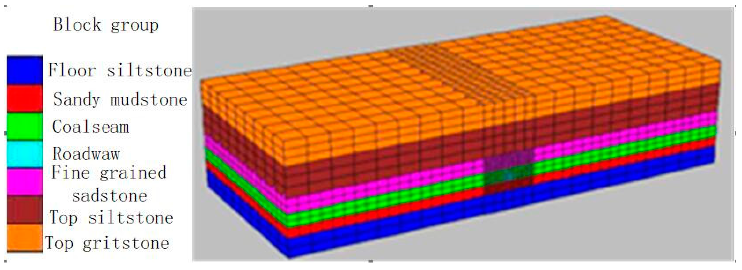
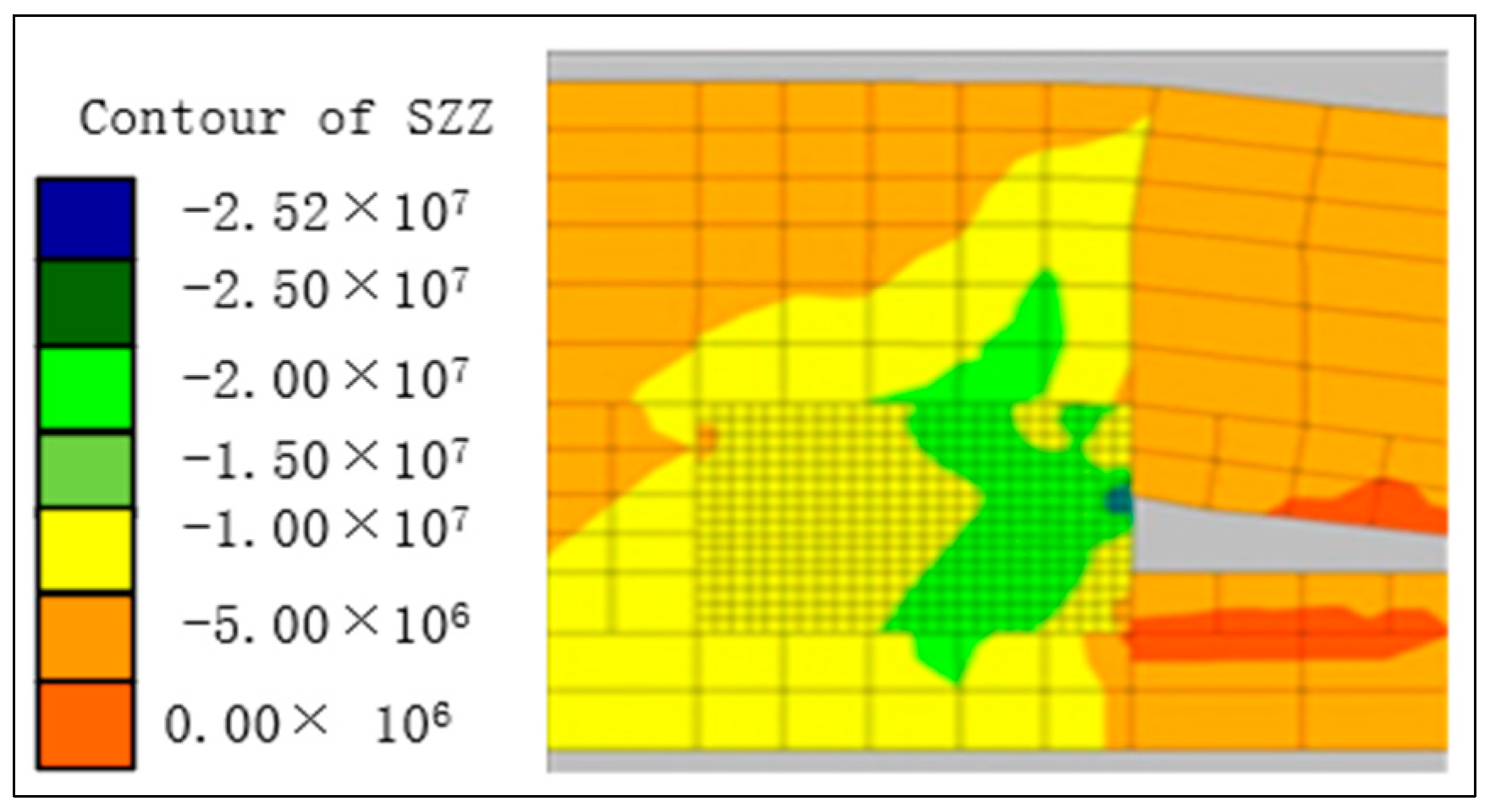
3.2. Numerical Calculation and Analysis of Optimum Width of a Narrow Coal Pillar

Combined with the above geological conditions, a numerical calculation model is established, which is 215.2 m wide, 90 m long and 52 m high. The working face of the upper section is 100 m wide. The width of this working face is 100 m, and the roadway along the void is 5.2 m. The coal seam 4-1 is near horizontal and the average thickness is 6 m, and is mined to its full height at one time. The gob side entry is 5.2 m wide and 4.0 m high, and is arranged along the floor. In order to make the calculation results more accurate, grid division is intensified around the excavation roadway, and the 3D calculation model is set up as seen in Figure 2. The front, back, left and right boundaries of the model are horizontal constraints; the bottom boundary is fully constrained, that is, the horizontal and vertical directions are fixed; a normal vertical stress of 1.98 MPa was applied at the top of the model to simulate the overburden weight. The rock mass mechanical parameters used in this simulation calculation are seen in Table 1.
The simulation includes the following steps: ① First, the coal seam of the previous working face is excavated. The distribution characteristics of lateral abutment pressure are analyzed after the calculation of goaf is stable; ② A small coal pillar with a certain width is reserved along the edge of the goaf of the upper working face, and the gob side entry is excavated and supported by bolts; ③ Finally, the coal seam of the working face is excavated, and the influence of the mining on the deformation and damage of the roadway along the goaf is analyzed, with the focus on the stability analysis of the small coal pillar along the goaf. This section only addresses the simulation content of ①, and the rest of the simulation content is described in detail in the third section.

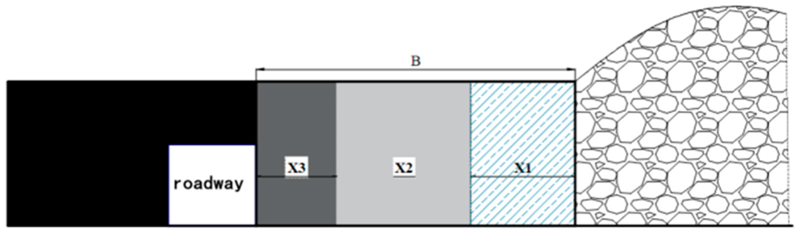
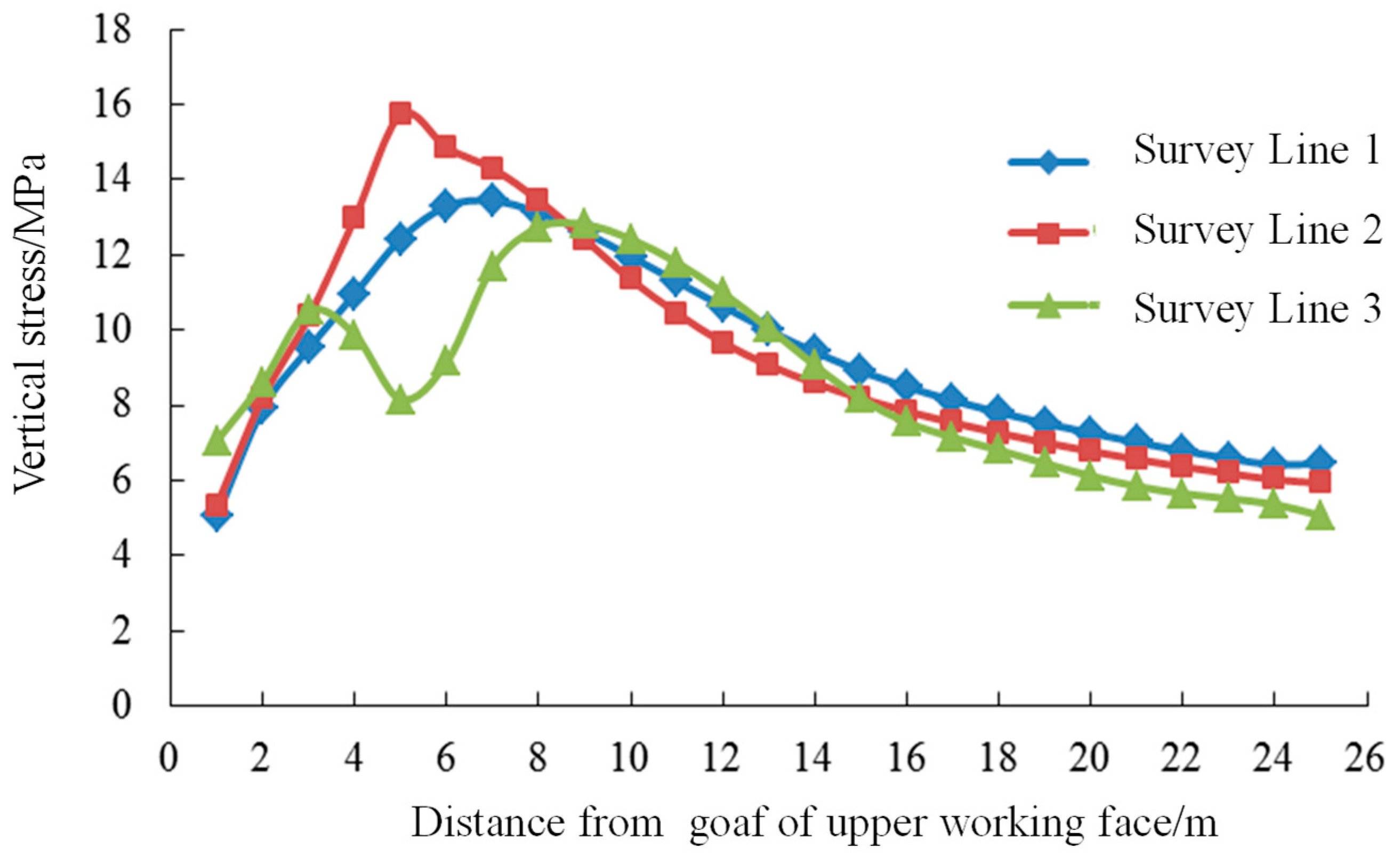
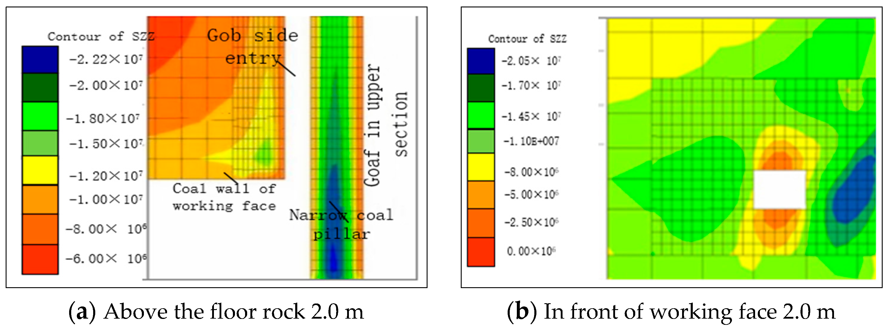
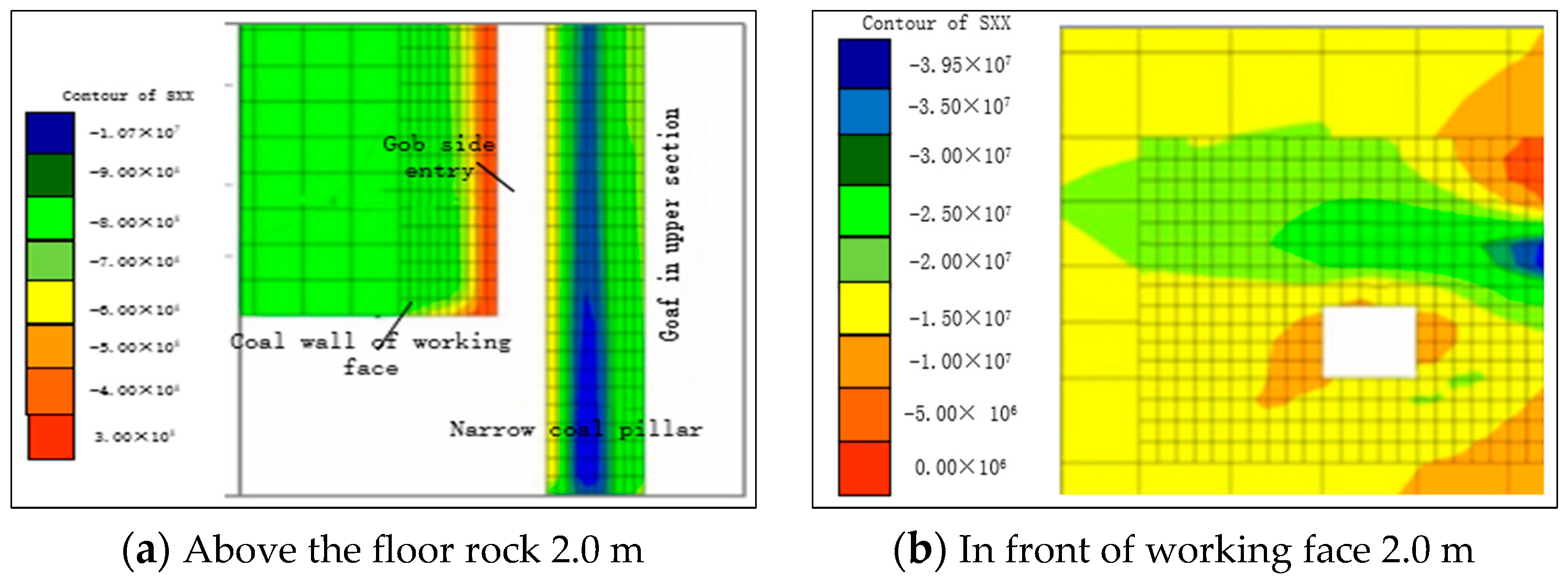
3.3. Distribution Characteristics of Lateral Abutment Pressure in Upper Working Face

The mining process of the working face destroys the equilibrium state of the in-situ stress area and causes the redistribution of the rock stress around the mining space. After the coal seam is mined, the arc triangle block structure plays a vital role in the upper part of the goaf. A new equilibrium support point will be formed in the upper strata of the goaf to achieve stress balance, thus forming lateral support stress at the coal wall of the goaf. After mining, the lateral support stress formed in the inclined direction of coal seam has a crucial influence on the layout of roadway; that is, it plays a crucial role in the width of roadway pillar. Therefore, the lateral abutment stress formed by the last working face is the large stress environment which determines the width of the coal pillar.
As shown in Figure 3, after the goaf in the upper section is stable, a high stress concentration area will be formed after it goes deep into a certain range of coal wall, and the excavation layout of gob side entry should avoid the stress peak area. In order to accurately analyze the distribution characteristics of the lateral abutment pressure in the goaf, three measuring lines were set up to monitor the lateral abutment pressure in the goaf after mining in the upper working face. Among them, line 1 is located in sandy mudstone of floor (1.0 m away from coal seam floor), line 2 is located in 4-1 coal seam (2.0 m away from coal seam floor) and line 3 is located in fine sandstone of roof (4.0 m away from coal seam roof). The monitoring results can be seen in Figure 4.
As the picture shows: ① the vertical stress in the coal seam and floor rock generally increases first and then decreases. The stress peak position is 5.0~6.0 m away from the edge of goaf. The stress in the coal seam is very concentrated. The maximum stress concentration factor is 3.14. ② the vertical stress distribution in the roof strata first increases and then decreases, and then increases and then decreases; ③ the vertical stress in the roof rock decreases within the scope of 3.0~5.0 m, and increases within the scope of 5.0~8.0 m, and the peak value of the latter is larger. Combined with the distribution characteristics of vertical stress in the coal seam and floor rock, it can be determined that the roof rock is fractured at about 5.0 m deep into the coal wall, resulting in a bimodal distribution of vertical stress; ④ the lateral vertical stress of goaf decreases in the range of 8.0~23.0 m, and keeps stable beyond 23.0 m from the goaf edge.
To sum up, the distribution graph of lateral abutment pressure in goaf has the following rules after mining of the upper working face: due to fracture of roof strata, the vertical stress of roof presents bimodal distribution, which leads to the high concentration of vertical stress in coal seam; in the range of 0~5.0 m from the edge of goaf, the effect of mining on the upper working face is the most significant, the deformation and failure of surrounding rock occur in different degrees, and the vertical stress in the coal body increases obviously; Within the scope of 5.0~23.0 m from the edge of goaf, the vertical stress in coal reduces gradually and tends to be stable beyond 23.0 m.

3.4. Determination of Narrow Coal Pillar Width

The width of narrow coal pillar is 9.81 m by theoretical calculation. The stress distribution of lateral support in 414,109 working face after stopping is analyzed by numerical calculation. The plastic zone width in lateral coal wall is 5.0~6.0 m. The width of plastic zone in lateral coal wall is 5.0 ~ 6.0 m. Considering the existence of stable rock strata in the anchor anchorage area, combined with the theoretical calculation and numerical calculation of coal pillar width, the width of narrow coal pillar should be 10 m in the auxiliary operation of 414,110 working face.

4. Simulation Analysis of Surrounding Rock Control of Gob Side Entry

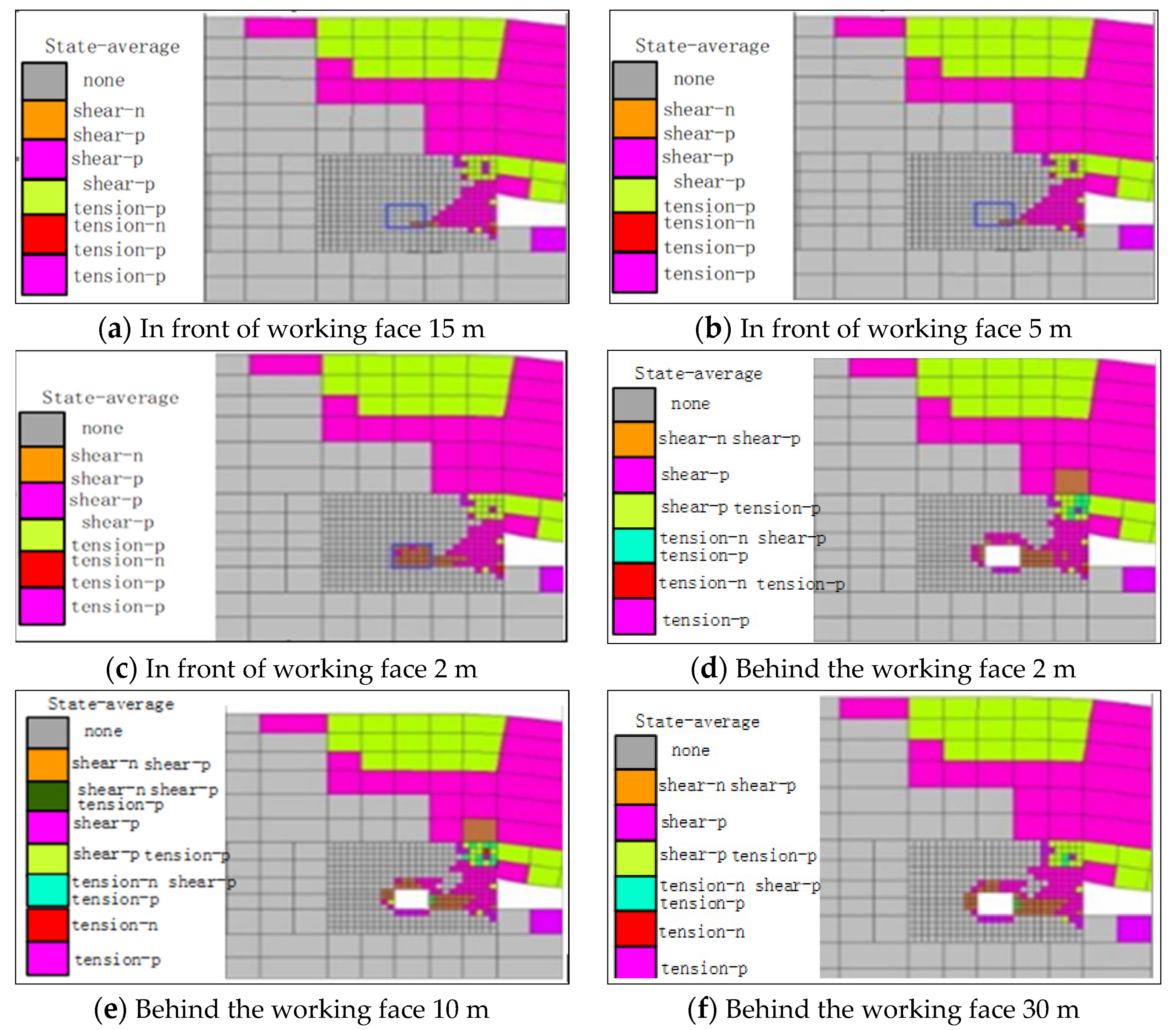
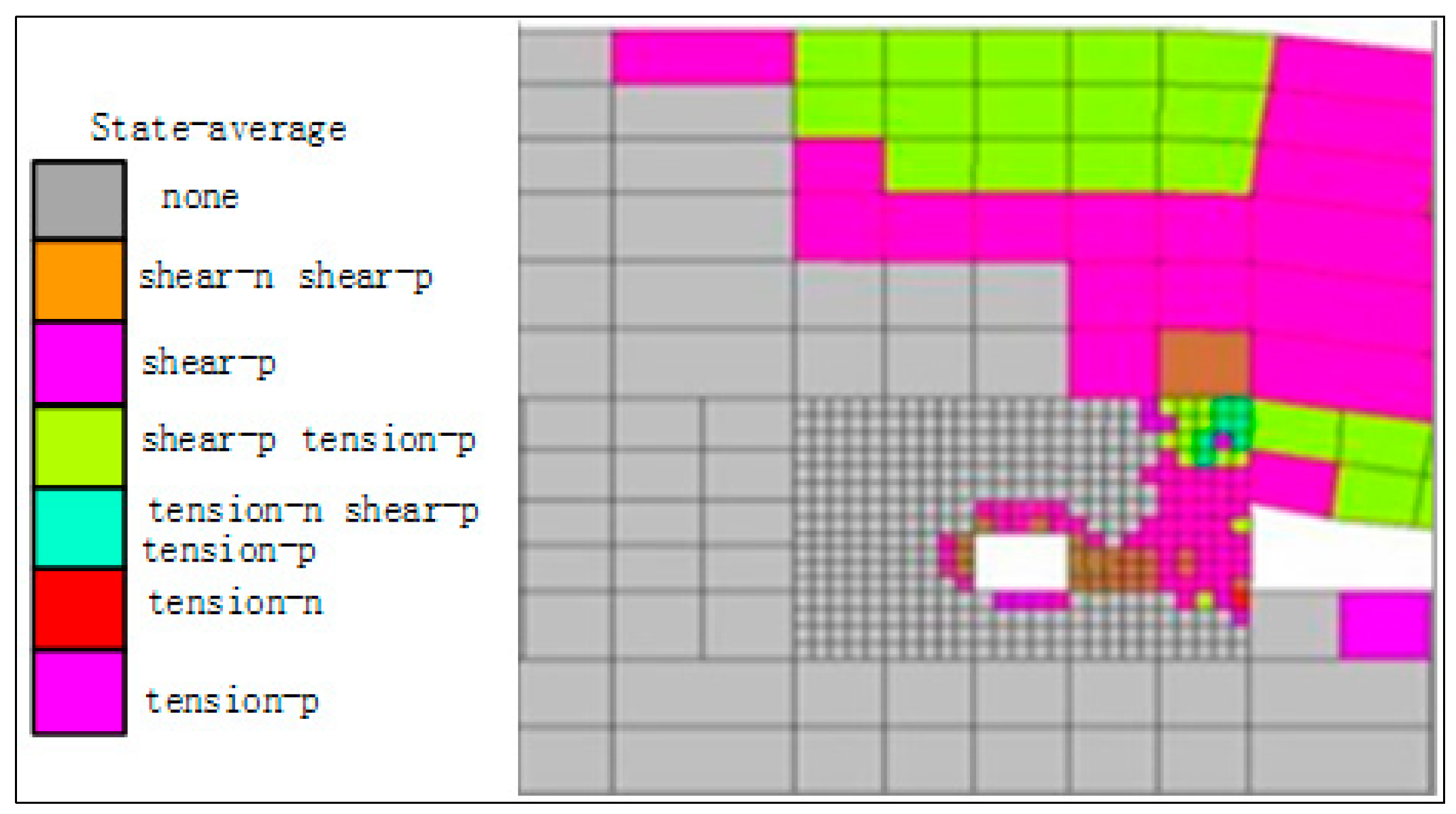
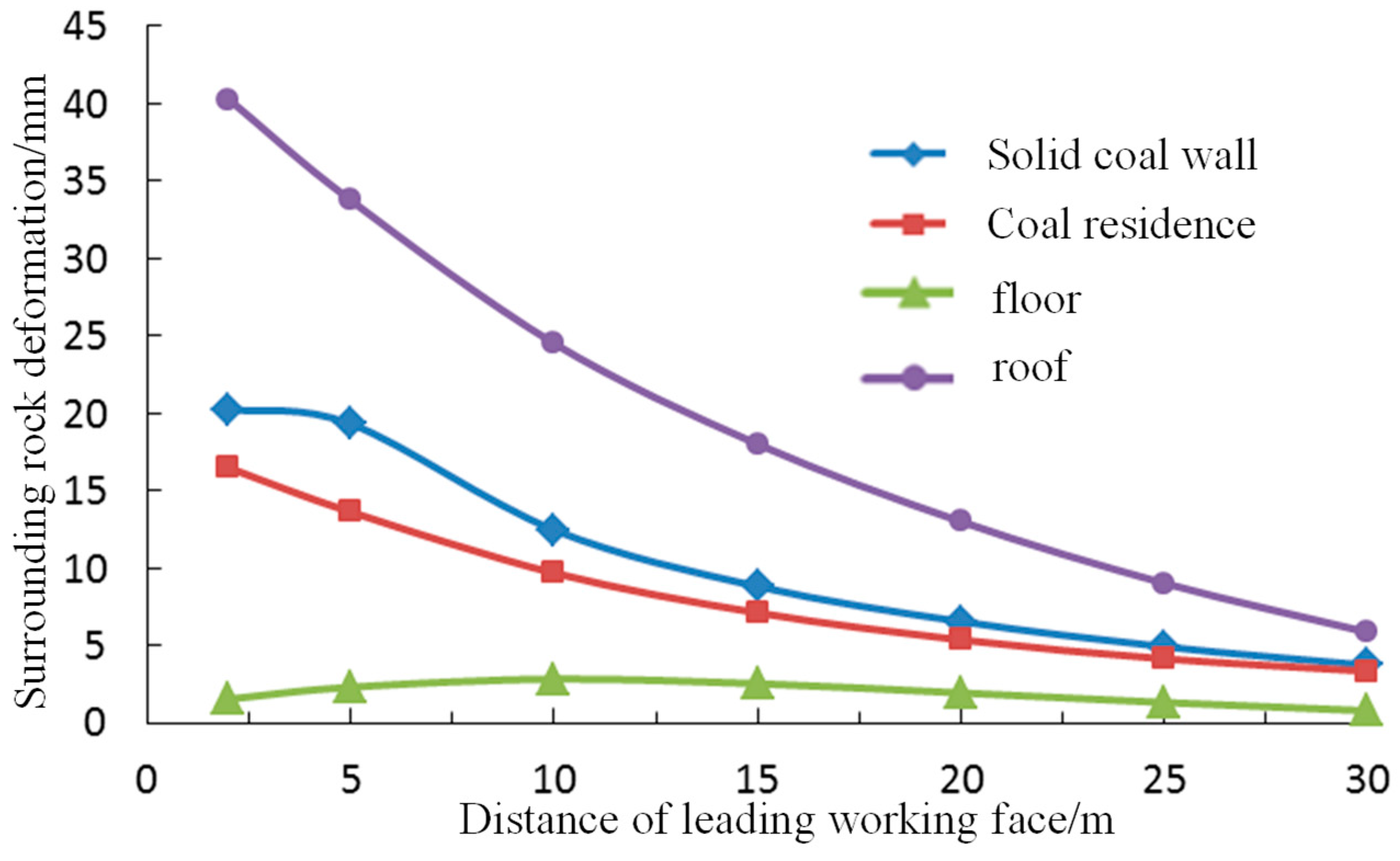
4.1. Deformation Characteristics and Cause Analysis of Roadway Surrounding Rock

The development process of plastic zone and deformation characteristics of surrounding rock were studied by numerical simulation, so as to analyse the deformation characteristics of surrounding rock. The establishment process is shown in Section 3.2 of numerical simulation model.
The results show that the development process of surrounding rock plastic zone of gob side entry during driving is seen in Figure 5.
According to Figure 5a, at 15.0 m precede driving face, the plastic failure distribution of surrounding rock is basically consistent with that of the upper working face after the mining stability, indicating that this area is outside the mining influence range of the driving face. According to Figure 5b, when working face is 5.0 m, the plastic failure range of surrounding rock does not increase obviously. However, under the dual effect of the lateral abutment pressure of goaf and influence of the driving of working face, the shear failure degree of surrounding rock of coal pillar wall is obviously intensified. According to Figure 5c, when 2.0 m precedes the working face, the plastic failure of the roadway section and the coal pillar side is significant. When 2.0 m behind the working face, the plastic failure range of surrounding rock increases significantly, the failure of coal pillar and roof connect into a piece, and the failure range of solid coal wall is distinctly bigger than that of floor, as shown in Figure 5d. Beyond 10 m from the rear of the working face, plastic failure of surrounding rock mainly develops and expands in a small range in the junction area between the roof and the coal pillar side, as shown in Figure 5e,f.
To sum up, during the tunneling along the goaf, the development sequence of surrounding rock plastic failure is roughly as follows: coal pillar side, roof, solid coal side, floor, and after tunneling, the plastic failure of coal pillar side and roof quickly becomes one piece and develops obviously.
Based on the waist line and the middle line of roadway, observation points were set up on the roof and floor and the left and right sides of gob-side roadway, and the deformation and failure law of surrounding rock during tunneling was observed and analyzed. The monitoring results are shown in Figure 6 (the first 320 steps are the deformation before the roadway is excavated).
The Figure 6 shows that the deformation and failure law of surrounding rock of gob side entry is as follows: deformation of coal pillar > roof subsidence > deformation of solid coal wall > deformation of floor. The deformation of coal pillar side is the largest, which is 2~3 times of roof subsidence and solid coal side deformation, and 5~6 times of floor deformation.
Combined with the above simulation results, the roadway deformation has the following obvious characteristics:
(1)
During the influence of excavation and the stable period after excavation, the two sides of the roadway move closer than roof and floor, and there is no significant difference between the solid side and the small pillar side; the roof subsidence is relatively large. The main reason is that the roof is greatly affected by the mining and roadway excavation in the upper section, and the roof condition becomes worse. At this time, the properties of floor surrounding rock are better than those of both sides and roof, and the floor heave is not obvious.
(2)
During the influence period of roadway excavation, the dilatancy of the surrounding rock in the shallow part of the roadway and the dislocation of the broken surrounding rock blocks are the main causes of surrounding rock deformation. The deformation of surrounding rock can be effectively controlled through reasonable roadway location and bolting parameters and early placement of bolting. After the roadway is stable, the main reason for roadway surrounding rock deformation is the creep of coal. Minimizing the number of days of roadway maintenance can reduce the amount of surrounding rock deformation during this period. The main reason for the large deformation during mining is that the advance abutment pressure affects the stability of the overlying rock structure, causing the continuous increase of surrounding rock stress and great increase of surrounding rock deformation speed and amount.
(3)
When the roadway is influenced by the mining, the deformation of surrounding rock is much larger than that of surrounding rock during excavation. The deformation of two sides of coal wall is large. The increase of vertical stress in the two sides leads to large deformation of the two sides. The deformation of solid coal side is a little bigger than that of narrow coal pillar side. The distribution of solid coal side deformation along the roadway height is uneven, and the approach of the lower part is larger than that of the lower part; the displacement of roof and floor is less than that of two sides, in which the quantity of floor heave is larger than that of roof subsidence. The main reason is that the larger vertical stress caused by mining causes the larger subsidence of two sides, which causes the larger floor heave. It is more serious near the solid coal wall, and the primary cause is that the vertical stress of solid coal wall increases greatly.
Therefore, according to the plastic failure development range and deformation failure law of surrounding rock, it is necessary to strengthen the support of coal pillar wall and roof adjacent to coal pillar wall.

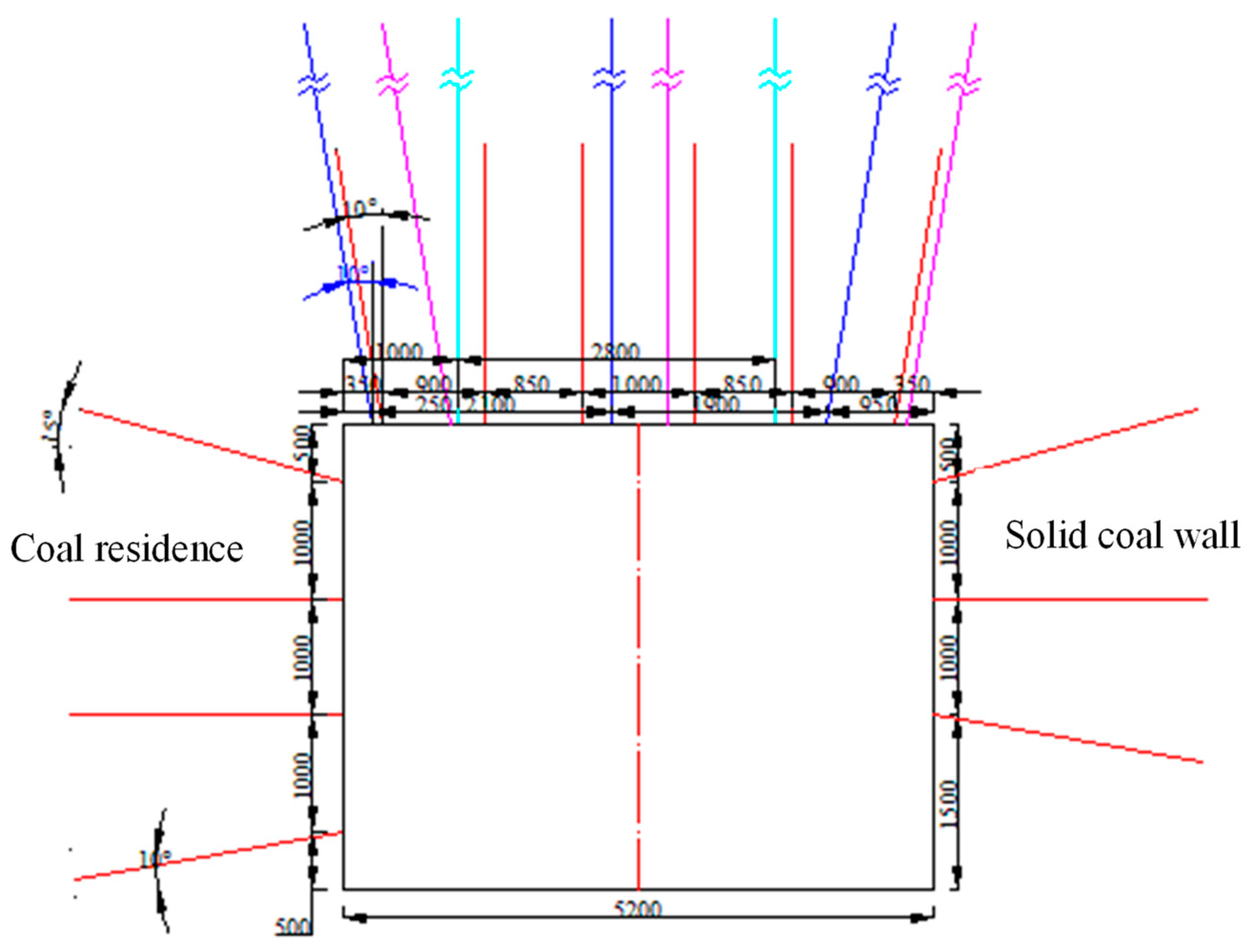
4.2. Bolt Support of Roadway Surrounding Rock

The supporting scheme of auxiliary haulage gateway in 414,110 working face is shown in Figure 7.
(1)
Roof support
The specifications are φ20 × 2400 mm left-hand ribbed steel bolts without longitudinal reinforcement, arranged with 6 bolts. The bolt spacing is 900 mm, 850 mm, 1000 mm, 850 mm, 900 mm, and the row spacing is 1000 mm. There are 2 bolts close to the wall. The distance between the bolts and the wall is 350 mm, with the roof vertical direction of 10° to the two sides inclined layout. The angle is inclined to the two sides and the other four are perpendicular to the roof and the anchoring force is not less than 105 kN, and the bolt torque is not less than 300 N·m;
(2)
Solid coal wall support
Three bolts are arranged, and the specification of upper left-handed ribbed steel bolt without longitudinal reinforcement is φ18 × 2200 mm [29]. The distance between the upper bolt and the roof is 500 mm, and the row distance between the bolts is 1000 × 1000 mm, and the vertical angle between the roof and floor bolts and the roadway side is 15°, 10°. The anchor is inclined to the top and bottom, respectively, the anchoring force is not less than 85 kN, the anchor torque is not less than 200 N·m and the anchor at the bottom angle is φ18 × 1100 mm;
(3)
Coal pillar support
Anchor rod: 4 bolts are arranged, the upper one adopts the specification of φ18 × 1800 mm left-hand ribbed steel bolts without longitudinal reinforcement [29], two in the middle of which are of the specification of φ18 × 2200 mm left-hand screw thread steel bolt without longitudinal reinforcement [30], and the lower one is made of stainless steel φ18 × 1100 mm left-hand screw thread steel bolt without longitudinal reinforcement, the spacing is 1000 mm, the row spacing is 1000 mm, the spacing between the upper bolt and the roof is 500 mm, and the angle between the bolt close to the top and floor and the roadway side in the vertical direction is 15°, 10° and the anchor force is not less than 8585 kN, and the torque of anchor is greater than 200 N·m.

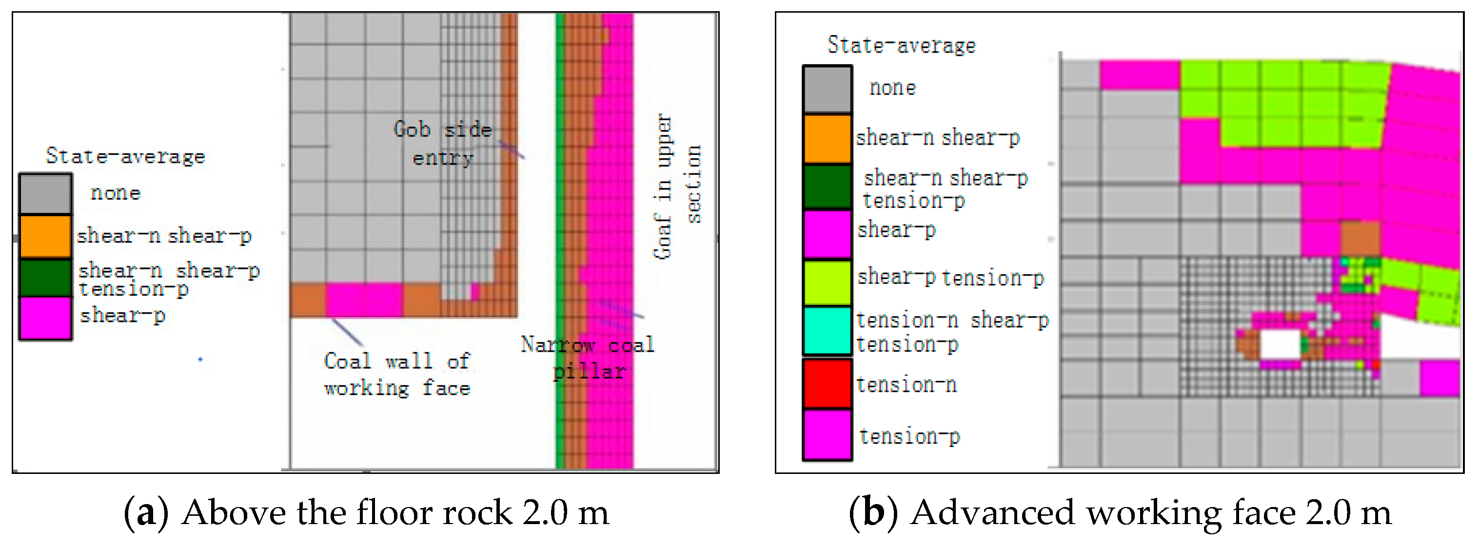
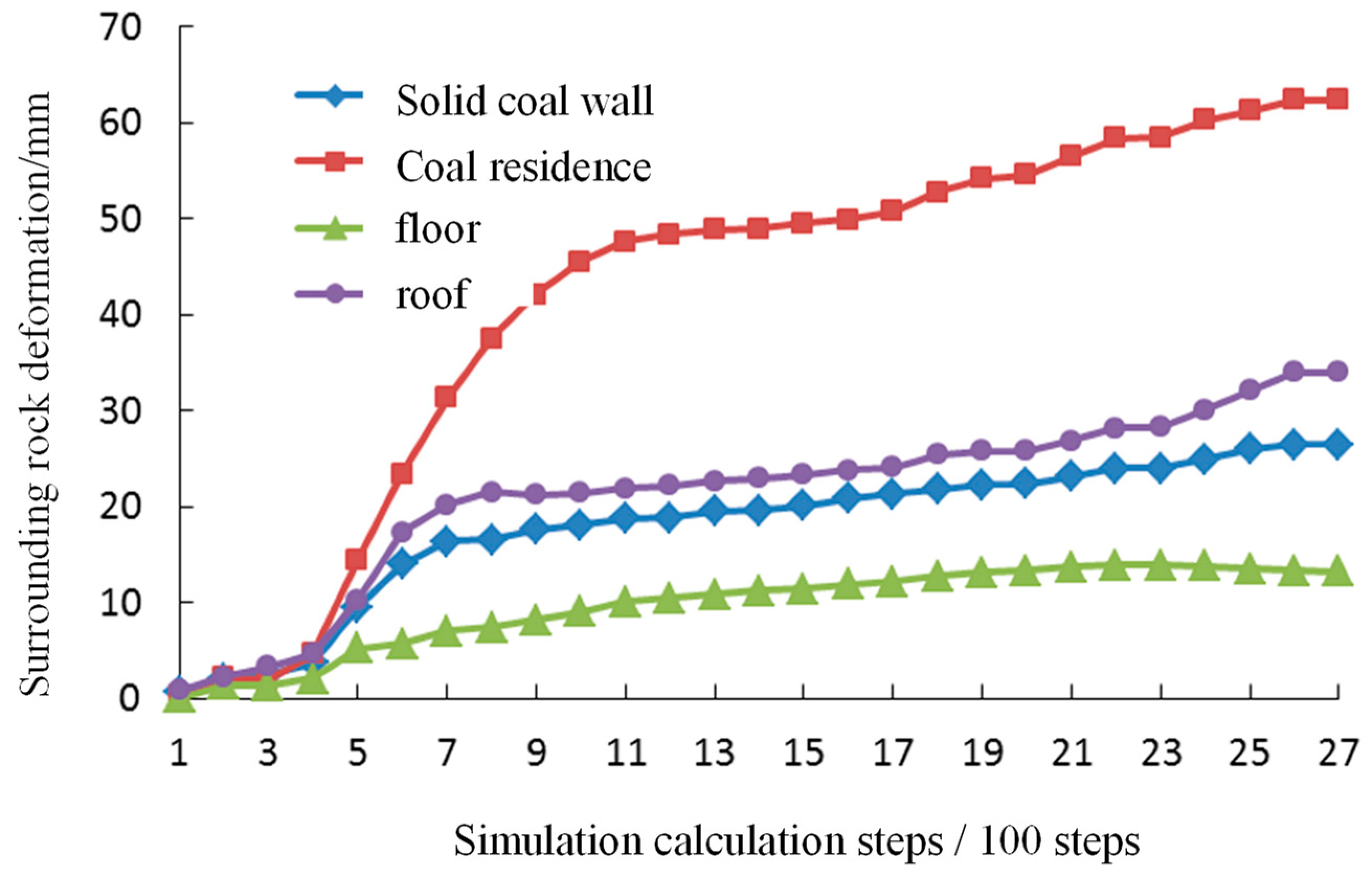
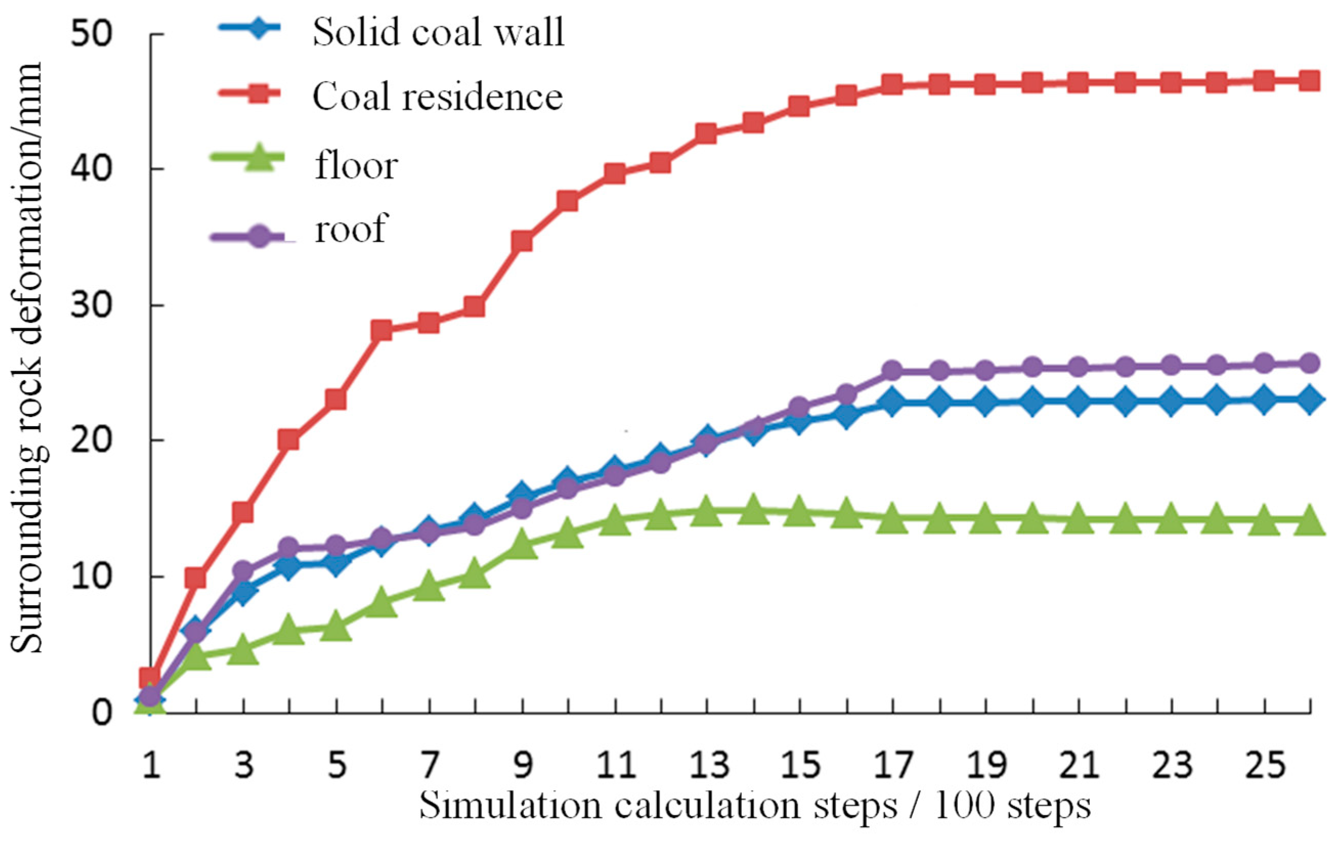
4.3. Analysis on Control Effect of Roadway Surrounding Rock

For analyzing the surrounding rock control effect under the aforementioned support parameters, numerical simulation software was used for monitoring the characteristics of the plastic zone of the surrounding rock and the deformation law of the surrounding rock during the tunneling and the stopping of the working face.
(1)
Effect of surrounding rock control during roadway excavation
Since the coal pillar wall is near the goaf of the upper working face, and affected by the lateral abutment pressure of the goaf, the development and expansion of the plastic failure of the surrounding rock of the coal gates close to gob is basically along the coal pillar wall -roadway roof -solid coal wall- roadway floor. The strong anchor cable and bolt can enhance the bearing ability and stability of the narrow coal pillar wall and reduce the plastic failure of surrounding rock; at the same time, the plastic failure of the roadway roof is reduced, and the top corner near the coal pillar is the most significant, as seen in Figure 8. The deformation and failure law of surrounding rock of road retained for next sublevel during excavation is seen in Figure 9.
Figure 8 and Figure 9 show that the deformation and failure of surrounding rock of roadway along gob under the action of high strength anchor bolt and cable support is significantly reduced compared with that without support. This is because the support of bolt and cable to the roof and two sides strengthens its bearing capacity, reduction of surrounding rock deformation, but increases the stress transferred to the floor, and the floor is exposed without any support and reinforcement measures. Therefore, the floor heave deformation of roadway increases, and the floor heave deformation increases less due to the higher strength of floor rock.
All in all, the deformation and damage of road retained for next sublevel is small under the support of high-strength anchor cable.
(2)
Control effect of surrounding rock during mining
Figure 10 shows that during the mining progress of the working face, the plastic failure of the solid coal wall is significantly increased because of the mining disturbance, and the plastic failure range of the narrow coal pillar wall along the goaf basically remains unchanged at this stage, but the damage degree of the surrounding rock is intensified. Similarly, the plastic failure range of the roadway roof and floor has no obvious increase. Therefore, from the distribution and development of surrounding rock plastic zone, the deformation of narrow coal pillar is the pivotal factor to determining the stability of lanes along the gob.
Figure 11 is the cloud photo of vertical stress distribution of surrounding rock of gob roadway during mining of this working face. As shown in the graph, with the advance of mining in this working face, the vertical stress rising zone of solid coal wall is formed at the junction of the coal wall and roadway section.
Figure 12 shows the distribution cloud diagram of horizontal stress in the surrounding rock of a gob roadway during the stopping of this working face. As shown in Figure 12, during the mining period, the distribution characteristics of the horizontal stress of the surrounding rock are basically consistent with the vertical stress, and the stress rising area of the solid coal wall is formed at the junction of the coal wall and the roadway section, but the stress concentration degree is obviously lower than the vertical stress; what is more, the stress concentration of the narrow coal pillar wall is also reduced, which is concentrated behind the gob of the working face.
Figure 13 shows that the deformation of surrounding rock of roadway along the goaf increases with the decrease of the distance from the working face under the action of advance abutment pressure. During the working face mining, the deformation and failure law of surrounding rock of roadway is as follows: roof subsidence deformation > solid coal wall deformation > narrow coal pillar wall deformation > floor bulging deformation. The reason is that the roadway along the goaf at this stage is mainly affected by the advance abutment stress of working face mining, so the deformation of roadway roof and integrated coal beside the roadway is larger.
In conclusion, during the mining period, the plastic failure range of the solid coal wall of the roadway along the goaf increases signally, and the stress rise zone is formed at the junction of the coal wall and the roadway section, and the failure deformation is the most significant; the plastic failure range of narrow coal pillar has little change, the damage degree is intensified and the stress concentration degree is high. The deformation failure has occurred during roadway excavation. At present, under the protection of the large structure of the overlying strata, the damage deformation growth is small.
The above analysis shows that the overall deformation and damage of surrounding rock of alone roadway is small during the mining period, and the effect of the proposed surrounding rock control support scheme is great.

5. Conclusions

(1)
It is the most advantageous for the stability of the roadway and the support pillar to arrange the roadway along the goaf in the area of stress reduction in the inner side of the coal wall at the edge of the goaf. According to the limit equilibrium theory, the width of the narrow pillar is 9.81 m.
(2)
The lateral support stress of goaf plays a crucial role in the width of roadway pillar. The lateral vertical stress of goaf decreases in the range of 8.0~23.0 m, and the width of plastic zone in the lateral coal body of working face 414,109 is 5.0~6.0 m. Combined with the theoretical calculation and numerical calculation, it is suggested that the width of narrow coal pillar should be 10 m in the auxiliary calculation of working face 414,110.
(3)
By analyzing of the development range of plastic failure of surrounding rock and the law of deformation and failure, the support design should focus on strengthening the support of the coal pillar side and the roof close to the coal pillar side.
(4)
The deformation and failure of surrounding rock of gob side entry under the action of high strength bolt and cable support is significantly reduced compared with that without support.

Author Contributions

Conceptualization by F.W.; methodology, X.S., H.W.; investigation, F.W., Y.W.; writing—original draft preparation, F.W., S.G.; writing—review and editing, S.G., Q.C.; supervision, Y.S., M.L.; funding acquisition, F.W., Q.C. All authors have read and agreed to the published version of the manuscript.

Funding

This research was supported by the projects of “National Natural Science Foundation of China (52174130)”.

Institutional Review Board Statement

Not applicable.

Informed Consent Statement

Not applicable.

Data Availability Statement

The data presented in this study are available on request from the corresponding author. The data are not publicly available due to privacy.

Conflicts of Interest

The authors declare no conflict of interest.

References

  1. Hou Chaojiong Team. Roadway Surrounding Rock Control; China University of Mining and Technology Press: Xuzhou, China, 2013. [Google Scholar]
  2. Li, C.; Liu, Y.; Bai, J.; Ge, Q. Study on stability of filling wall under lateral large-span composite hinge fracture of hard critical block. Sci. Prog. 2021, 104, 21694. [Google Scholar] [CrossRef] [PubMed]
  3. Wang, Z.Q.; Shi, L.; Wang, P.; Wu, C. A Novel Gob-Side Entry Method in China: A Case Study. Geotech. Geol. Eng. 2019, 38, 215–226. [Google Scholar] [CrossRef]
  4. Fei, L.; Han, Y. Deformation Mechanismand Control of the Surrounding Rock during GobSide Entry Driving along Deeply Fully Mechanized Caving Island Working Face. Geofluids 2021, 2021, 1–12. [Google Scholar] [CrossRef]
  5. Fuxing, X.; Sandro, C. Control of Gob-Side Roadway with Large Mining Height in Inclined Thick Coal Seam: A Case Study. Shock. Vib. 2021, 2021, 6687244. [Google Scholar] [CrossRef]
  6. Li, X.; Zhao, Y.; He, W.; Li, L.; He, F. Study on Coal Pillar Width and Surrounding Rock Control of Gob-Side Entry in Extra-thick Coal Seam. Geotech. Geol. Eng. 2020, 38, 1–14. [Google Scholar] [CrossRef]
  7. Wang, W.; Feng, T.; Hou, C. Analysis on relationship between stress distribution of solid coal wall and surrounding rock damage in gob side entry driving. J. Rock Mech. Eng. 2002, 11, 1590–1593. [Google Scholar]
  8. Zhang, N.; Li, X.; Gao, M. Pre tension support and engineering application of gob side entry driving in Yingmei mining face. J. Rock Mech. Eng. 2004, 12, 2100–2105. [Google Scholar]
  9. Bai, J.; Hou, C.; Huang, H. Numerical simulation study on stability of narrow coal pillar in gob side entry driving. J. Rock Mech. Eng. 2004, 20, 3475–3479. [Google Scholar]
  10. Lu, S.; Liu, S.; Wan, Z.; Zhang, H.; Xing, K.; He, X. Deformation and control measures of narrow coal pillar in gob side entry driving. Min. Res. Dev. 2020, 40, 28–31. [Google Scholar]
  11. Li, J. Study on reasonable width of narrow coal pillar in gob side entry driving. Shandong Coal Sci. Technol. 2020, 5, 73–75+78. [Google Scholar]
  12. Zhang, K. Research on reasonable width design of narrow coal pillar in gob side entry driving. Energy Environ. Prot. 2019, 41, 159–162+166. [Google Scholar]
  13. Yu, J. Stability analysis of narrow coal pillar and Research on surrounding rock control technology of gob side entry in fully mechanized top coal caving. Coal Mine Modernization 2020, 1, 139–141+144. [Google Scholar]
  14. Xue, C.; Cao, A.; Guo, W.; Wang, S.; Liu, Y.; Shen, Z.; Wang, P. Mechanism of Coal Burst and Prevention Practice in Deep Asymmetric Isolated Coal Pillar: A Case Study from YaoQiao Coal Mine. Shock. Vib. 2021, 2021, 3751146. [Google Scholar] [CrossRef]
  15. Wang, Z.; Zhong, Q.; Wang, P. Research on narrow coal pillar width of gob side entry driving in high stress soft rock gently inclined coal seam. Coal Mine Saf. 2020, 51, 216–221+228. [Google Scholar]
  16. Li, W. Technology and application of gob side entry driving in 2102 working face of Heilong coal industry. Coal Sci. Technol. 2019, 40, 79–82. [Google Scholar]
  17. Li, J. Study on stress and surrounding rock deformation law of narrow coal pillar in gob side entry driving. Coal Technol. 2019, 38, 43–46. [Google Scholar]
  18. Chen, J.; Liu, P.; Zhao, H.; Zhang, C.; Zhang, J. Analytical studying the axial performance of fully encapsulated rock bolts. Eng. Fail. Anal. 2021, 128, 105580. [Google Scholar] [CrossRef]
  19. Chen, J.; Zhao, H.; He, F.; Zhang, J.; Tao, K. Studying the performance of fully encapsulated rock bolts with modified structural elements. Int. J. Coal Sci. Technol. 2021, 8, 64–76. [Google Scholar] [CrossRef]
  20. Chang, Q.; Tang, W.; Xu, Y.; Zhou, H. Research on the width of filling body in gob-side entry retaining with high-water materials. Int. J. Min. Sci. Technol. 2018, 28, 519–524. [Google Scholar] [CrossRef]
  21. Chang, Q.L.; Sun, Y.F.; Leng, Q.; Liu, Z.X.; Zhou, H.Q.; Sun, Y.T. Stability Analysis of Paste Filling Roof by Cut and Fill Mining. Sustainability 2021, 13, 10899. [Google Scholar] [CrossRef]
  22. Chen, X.; Zhang, T.; Wang, Y. Study on influencing factors of surrounding rock deformation and asymmetric support technology for roadway driving along goaf with narrow coal pillars. J. Henan Polytech. Univ. 2021, 40, 24–33. [Google Scholar]
  23. Zhang, H.; Zuo, A. Reasonable width of coal pillar and asymmetric support technology in gob-side entry. Saf. Coal Mines. 2021, 52, 129–135. [Google Scholar]
  24. Xu, Z.; Li, Q.; Li, X. Overburden Migration and Failure Characteristics in Mining Shallow Buried Coal Seam with Thick Loose Layer. Adv. Mater. Sci. Eng. 2020, 2020, 1–12. [Google Scholar] [CrossRef]
  25. Han, C.; Yang, H.; Zhang, N.; Li, X.; Liu, Y.; Liu, W.; Yao, W. Study on Reasonable Coal Pillar Width of Gob-Side Roadway Excavating with Multi-Layer Hard Roof in Western Deep Mine. Geotech. Geol. Eng. 2021, prepublish. [Google Scholar] [CrossRef]
  26. Chen, A. Width Design of Small Coal Pillar of Gob-Side Entry Driving in Soft Rock Working Face and Its Application of Zaoquan Coal Mine. Adv. Civ. Eng. 2021, 2021, 1–10. [Google Scholar] [CrossRef]
  27. Zhang, T.; Wu, J.; Chen, Y.; Ding, H.; Ma, H.; Feng, R. The Relationship between Mining-Induced Stress and Coal Gas under an Optimized Support Scheme: A Case Study in the Guanyinshan Coal Mine, China. Geofluids 2021, 2021, 1–17. [Google Scholar] [CrossRef]
  28. Ming, Z.; Shuai, Z.; Yong, C. Reasonable Width of Narrow Coal Pillar of Gob-side Entry Driving in Large Mining Height. IOP Conf. Ser.: Earth Environ. Sci. 2017, 59, 12025. [Google Scholar] [CrossRef] [Green Version]
  29. Tai, Y.; Yu, B.; Xia, B.; Li, Z.; Xia, H. Research on stress release for the gob-side roadway using the roof-cutting technology with a chainsaw arm. R. Soc. Open Sci. 2020, 7. [Google Scholar] [CrossRef] [Green Version]
  30. Qi, F.; Zhou, Y.; Li, J.; Wang, E.; Cao, Z.; Li, N. Top-coal deformation control of gob-side entry with narrow pillars and its application for fully mechanized mining face. Int. J. Min. Sci. Technol. 2016, 26, 417–422. [Google Scholar] [CrossRef]
Figure 1. Calculation chart of narrow coal pillar width.
Sustainability 14 04848 g001
Figure 2. Numerical calculation model.
Sustainability 14 04848 g002
Figure 3. Cloud chart of lateral abutment pressure distribution after goaf stability in the upper section.
Sustainability 14 04848 g003
Figure 4. Distribution law of lateral vertical stress in goaf.
Sustainability 14 04848 g004
Figure 5. Development law of plastic failure of surrounding rock during roadway driving.
Sustainability 14 04848 g005
Figure 6. Deformation and failure law of surrounding rock during roadway driving.
Sustainability 14 04848 g006
Figure 7. Supporting design scheme of auxiliary transport gateway roadway in 414,110 working face.
Sustainability 14 04848 g007
Figure 8. Development characteristics of plastic zone of surrounding rock during roadway driving.
Sustainability 14 04848 g008
Figure 9. Deformation and failure law of surrounding rock under roadway support condition during tunneling.
Sustainability 14 04848 g009
Figure 10. Development characteristics of plastic failure of surrounding rock during mining.
Sustainability 14 04848 g010
Figure 11. Vertical stress distribution nephogram of surrounding rock during mining.
Sustainability 14 04848 g011
Figure 12. Cloud chart of horizontal stress distribution of surrounding rock during mining.
Sustainability 14 04848 g012
Figure 13. Deformation characteristics of roadway surrounding rock during mining.
Sustainability 14 04848 g013
Table 1. Physical and mechanical parameters of coal and rock mass.
Stratum NameBulk Modulus/GPaShear Modulus/GPaDensity/kg/m3Cohesion/MPaInternal Friction Angle/°Tensile Strength/MPa
Bottom siltstone9.706.6124702.4036.21.86
Bottom sandy mudstone7.305.2125604.4032.41.26
4-1 coal seam2.831.8714601.4127.30.83
Top fine grained sandstone7.605.1924306.0027.61.87
Top siltstone9.666.4423802.7036.32.34
Top gritstone10.306.8724204.1431.43.79
Publisher’s Note: MDPI stays neutral with regard to jurisdictional claims in published maps and institutional affiliations.

