Article

Aesthetic Aerogel Window Design for Sustainable Buildings

by
Mary K. Carroll
1,2,*,
Ann M. Anderson
2,3,*,
Sri Teja Mangu
3,
Zineb Hajjaj
3 and
Margeaux Capron
1
1
Department of Chemistry, Union College, Schenectady, NY 12308, USA
2
SunThru LLC, Scotia, NY 12302, USA
3
Department of Mechanical Engineering, Union College, Schenectady, NY 12308, USA
*
Authors to whom correspondence should be addressed.
Sustainability 2022, 14(5), 2887; https://doi.org/10.3390/su14052887
Submission received: 18 December 2021 / Revised: 25 February 2022 / Accepted: 28 February 2022 / Published: 2 March 2022
(This article belongs to the Special Issue Sustainable Materials for Thermal and Noise Insulation of Buildings)

Abstract

:
Transport of heat through windows accounts for more than 25% of heating and cooling losses in residential buildings. Silica-based aerogels are translucent with extremely low thermal conductivity, which make them attractive for incorporation into the interspaces of glazing units. Widespread incorporation of monolithic-silica-aerogel-based windows could result in significant energy savings associated with the heating and cooling of buildings. However, monolithic silica aerogels do not have the optical clarity of vision glass, due to light scattering by the solid matrix, and often have surface imperfections, both of which render these materials less appealing for glazing applications. Here, we demonstrate a variety of approaches to preparing aesthetically pleasing monolithic silica aerogel by a rapid supercritical extraction method for incorporation into glazing units, including: (1) process improvements that result in monoliths with higher visible light transmission; (2) innovative mold design for the preparation of uniform aerogel monoliths; (3) glazing designs that use thinner monoliths; and (4) the incorporation of artistic effects using dyes and laser etching to prepare glazing units with mosaic- or stained-glass-like patterns in which surface imperfections are perceived as features of the design rather than flaws.

1. Introduction

Windows and other glazing units are responsible for a significant portion of thermal loss in buildings. Recognition of the economic impact and contribution to global climate change of this energy loss is leading to increasingly stringent recommendations and regulations for both new construction and retrofitting of older buildings. Two examples are the US government’s ENERGY STAR ratings and the Energy Performance of Building Directive of the EU Member States. Jelle et al. provide an extensive review of current fenestration technologies, which include: (a) double- and triple-pane windows; (b) window systems filled with noble gases; (c) vacuum glazing; (d) low-emissivity coatings; (e) suspended films (between glass glazings); (f) photochromic glass; (g) smart windows (user-controlled variable tint); and (h) aerogel-granule-filled windows [1].
Silica aerogels have several properties that render them attractive for high-performance window applications. These low-density mesoporous materials have low thermal, electrical, and acoustic conductivity and are optically translucent [2] or even transparent [3,4]. As a result, there has been considerable interest in the implementation of these materials in glazing applications for sustainable buildings. This topic is the subject of a recent mini-review article [5], as well as an extensive recent review article by Buratti et al. that provides an excellent overview of the work in this area [6]. Here, a brief summary of work relevant to this study is provided.
Silica aerogel is synthesized using a silica precursor, most commonly through a sol-gel process involving an alkoxide such as tetramethyl orthosilicate (TMOS) or tetraethyl orthosilicate (TEOS). When the silica precursor is mixed with a water/solvent mixture and then a base or acid catalyst is added, the mixture undergoes hydrolysis, forming a sol, followed by condensation reactions to yield a wet silica gel. If this wet gel is then carefully dried, so that little or no shrinkage occurs, an aerogel is formed. This can be accomplished using supercritical extraction, ambient drying, or freeze drying [2,7,8,9]. Depending on the processing method chosen, one can produce granular, powdered, or monolithic aerogel.
Commercial glazing products based on granular aerogel are available, including Lumira® produced by Cabot [10]. Aerogel granules are used to fill the interspace between panes, resulting in highly insulating, but not transparent, fenestration units [11,12,13,14,15,16,17,18,19,20]. These products are suitable for use in applications where diffuse light is desired, including skylights and some daylighting applications.
Fabricating monolithic silica aerogels that have the size and the optical properties suitable for incorporation into vision glass glazing units would open this technology to a broader market but is significantly more challenging [6,20]. Research in this area has been ongoing for decades. Indeed, Rubin and Lampert described the use of transparent silica aerogels as window insulation in 1983 [21]. Duer and Svendsen characterized the excellent thermal performance of monolithic silica aerogel in glazing units, while noting that light scattering posed a significant disadvantage [22]. Schultz and co-workers published a series of papers in the mid-2000s demonstrating the insulating properties of aerogel glazings [23,24,25]. In the mid-2010s, Berardi developed a monolithic aerogel glazing unit for a retrofitting application [26]; Buratti and co-workers investigated the thermal, optical, and acoustic performance of aerogel glazing systems based on granular and monolithic aerogel [12,13,14]; and our group demonstrated the use of a rapid supercritical extraction (RSCE) method to yield monolithic silica aerogel for window applications [27]. In collaboration with Buratti’s group, we investigated the properties of RSCE-fabricated aerogels [28,29] and their performance in aerogel-monolith-based window prototypes [29]. Recently, Buratti et al. extended that work to include experimental and numerical energy assessment of a monolithic-silica-aerogel-containing glazing prototype [30]. Golder et al. used experimental measurements and employed computational fluid dynamics to study aerogel-based window and wall insulation [31].
In addition to academic and national laboratory research efforts, there are several start-up companies working in this area, including SunThru [32] and AeroShield [33] in the US and Tiem Factory [34] in Japan. Of note, these companies employ different fabrication approaches. AeroShield uses CO2 supercritical extraction, Tiem Factory employs an ambient-drying method, and SunThru uses the rapid supercritical extraction (RSCE) method developed and patented by our group at Union College [35,36,37].
As the prior studies by our group and others have shown, monolithic silica aerogels have superior insulating ability but do not generally have the optical clarity of glass. This is due to light scattering by the solid matrix. In addition, monolithic silica aerogels often have surface imperfections. Both factors render these materials unappealing for vision window glazing applications. In one approach to improve the aesthetics, Büttner et al. used monolithic silica aerogel pillars within an evacuated glazing unit so that only a small area (~10%) of the window was obscured by the aerogel [38]. Another approach is to improve the optical clarity through changes in the chemical precursor recipe. The effect of the precursor recipe on the properties, including light transmission properties and structural integrity, of silica aerogels has been studied [4,39,40,41,42]. One important parameter is the amount of catalyst used, with studies showing that increasing the amount will improve the transmittance; unfortunately, this can be at the expense of structural integrity.
In this work, we describe several approaches that can be used to improve the aesthetics of aerogel-monolith-based glazing systems. First, we demonstrate methods for improving optical clarity through (a) variations in the chemical precursor recipes for aerogels processed using RSCE and (b) the use of an innovative approach to mold design to prepare aerogel monoliths of varying thicknesses. Thinner monoliths have shorter optical pathlengths and therefore result in less scatter, which make them more attractive for window applications.
We then describe an approach to making aerogel monoliths more visually appealing by “masking” some of the imperfections through the use of dyes to produce colored materials and through laser etching of the aerogel surfaces. The RSCE process facilitates incorporation of dyes into silica aerogel. Because there are no solvent-exchange steps, washing out or leaching of dye is not of concern; however, it is necessary to use dyes that do not decompose under the high-temperature, high-pressure conditions employed in RSCE. Here, we report on several studies to incorporate a variety of dyes into small aerogel samples and then scale up to larger sizes. Plain or dye-containing aerogel monoliths can be readily etched using a laser engraving system, resulting in eye-catching designs [43,44,45].
Finally, we demonstrate the construction of three prototype glazing units, each including monolithic silica aerogel and incorporating one or more of these improvements.

2. Materials and Methods

2.1. Aerogel Monolith Preparation

2.1.1. Wet-Gel Synthesis

In this work, we used tetramethyl orthosilicate (TMOS, Sigma-Aldrich, St. Louis, MO, USA >98%) as the silica precursor, methanol (Fisher Scientific, Waltham, MI, USA, certified ACS reagent grade) and deionized water (DI, in-house) as solvents, and 1.5 M aqueous ammonia (prepared via dilution of Fisher Scientific, certified ACS Plus, with DI water) as a catalyst.
For a study on the effect of precursor recipe on visible light transmittance, the precursor recipes shown in Table 1 were employed.
To prepare dye-doped aerogels, the dyes Rhodamine 6G (~95% dye), Rhodamine B (~80% dye), and Fluorescein (~95% dye) were obtained from Sigma-Aldrich. Methanol solutions of the dyes were prepared (Table 2) and used in place of some or all of the methanol in the precursor mixture.

2.1.2. Mold Details

Several different molds were used to make the aerogels that are presented here. For making small aerogel samples, we used a 13.3 × 13.3 × 1.3 cm mold with nine 1.9 × 1.9 × 1.3 cm holes to make 4.5 mL aerogel samples. This mold utilized conventional gasket material consisting of a 0.013 mm thick layer of stainless-steel foil and 1.6 mm thick layer of graphite on the bottom and top surfaces of the mold [37].
For larger aerogels, we use an innovative three-piece mold conditioned with high-temperature vacuum grease, which allows us to make flat, uniform aerogels without the need for a gasket layer. This type of mold (shown in Figure 1) is made from 4140 alloy steel and contains a top, middle, and bottom piece. A series of vent holes have been drilled through the top piece to vent the supercritical fluid. To assemble the mold, vacuum grease is applied to the outer edge of the bottom piece (Figure 1a) which is then inserted into the middle piece (Figure 1b). The middle piece includes an access port for a pressure transducer that can be used to monitor the RSCE process. Once the bottom and middle pieces are assembled, the precursor solution is poured into the cavity formed by the assembly. Then the top piece (Figure 1c), which is also treated with a layer of vacuum grease, is placed on top of the assembly. Small inserts on the outside of the top and bottom mold are used to separate the mold pieces after RSCE processing. Several different versions of this mold were used to make 10 × 11 × 1.5 cm, 13 × 12.5 × 0.5 cm, and 13 × 12.5 × 0.29 cm aerogels. A video and written protocol for use of these molds can be found in [45].

2.1.3. Drying Method

We use a rapid supercritical extraction method (RSCE) to dry the wet gel [35,36,37]. The materials used in the RSCE process include a metal mold into which the precursor mixture is poured, gasket material (either stainless steel foil and graphite or vacuum grease), and a hydraulic hot press (in these studies we used a 30-ton Tetrahedron MTP-14 press).
The hot press seals and heats the mold to a supercritical state, controllably releases the supercritical gases, and then cools the mold. The processing involves four steps as outlined in Table 3. In general, the procedure takes 5–6 h to complete.

2.2. Aerogel Post-Processing

2.2.1. Heat Treatment

The translucency of aerogel monoliths can be improved using heat treatment [27,40,42]. We used a Thermolyne furnace to study the effect of heat treatment on a 10 × 10 cm, 3 mm thick aerogel sample. The furnace was heated to 425 °C and the aerogel sample was then placed in the furnace, supported on a ceramic crucible, for 45 min. In addition, we investigated the effect of heating 10 × 10 cm, 3 mm thick samples to 500, 600, 700, or 800 °C for a period of 12 h. In these cases, the samples were placed on a crucible in the oven, which was ramped from ambient temperature to the set temperature at a rate of 3 °C/min.

2.2.2. Etching and Cutting

Low-power laser engraving can be used to etch and cut aerogel monoliths with little damage to the aerogel (other than to the surface) [43,44,45]. To demonstrate the ability to aesthetically enhance the surfaces of dyed and undyed aerogels, we used a drawing program (CorelDraw) to draw patterns and images that we then sent to a 50 W Epilog Laser Helix, varying speed and power settings as appropriate for each sample. Stanec et al. present a full protocol of the etching process [45].

2.2.3. Prototype Assembly

In this paper, we describe three insulated glazing unit (IGU) prototypes. The first two were prepared for thermal testing and the third as a demonstration of an aesthetic approach to an aerogel IGU.
A 30.5 × 30.5 × 2.5 cm aerogel IGU was fabricated using 13 pieces cut from 10 × 10 × 1.27 cm silica aerogel monolith and packaged between two 6.35 mm thick glass sheets. The aerogel monoliths were fabricated using Recipe A-1.
A 26.7 × 26.7 × 1.8 cm aerogel IGU prototype was fabricated using thin (0.5 cm thick) silica aerogel monoliths that were packaged between two 6.35 mm thick glass sheets. The aerogel monoliths were fabricated using Recipe B-2.
A prototype 3 × 3 style window was formed from a variety of plain (undyed) and dye-containing aerogels monoliths, with each of size 5 × 5 × 0.5 cm. Panes were laser-cut from larger monoliths and placed in a 3-D printed frame, which was sandwiched between 3.18 mm thick panes of glass.
The overall process employed for making the aerogels described herein is shown schematically in Figure 2.

2.3. Characterization Methods

2.3.1. Light Transmittance

An Agilent Cary 8454 UV-Visible diode-array spectrophotometer was used to characterize the aerogel monoliths. Transmittance through an aerogel monolith was measured relative to an air blank over the spectral range of the instrument (190 to 1100 nm). Average light transmittance (%T) was calculated over the 380 to 720 nm range.

2.3.2. Thermal Performance

The larger prototype glazing systems were sent to a certified testing agency and evaluated using ASTM C518-17: Standard Test Method for Steady State Thermal Transmission Properties by Means of the Heat Flow Meter Apparatus.

3. Results and Discussion

3.1. Approaches to Improve the Translucency of Aerogel Monoliths

3.1.1. Variation in Chemical Precursor Recipe

A series of samples were made using the recipes listed in Table 1. Recipe A-1 is the recipe that we typically use to make silica aerogels. In Recipe A-2, we doubled the amount of catalyst. In Recipe B-1, we reduced the amount of methanol and increased the amount of catalyst (relative to A-1). In Recipes B-2 and B-3 we further increased the catalyst. We used a three-piece mold as described in the experimental section to make 13 × 12.5 × 0.5 cm aerogels. The samples were processed using a maximum force of 267 kN, a 55 min dwell time at the end of the heating step, and heating/cooling rates of 1.1 to 2.2 °C/min.
Images of the resulting aerogels are shown in Figure 3. All samples are monolithic with high translucency. Figure 4 plots an example spectrum for each type of sample. The average percent transmittance over the range 380 to 720 nm for each sample is listed in the legend. The results show that small variations in the precursor recipe, including increasing the amount of catalyst employed, can result in significant increases in the transparency of these materials.
Some of the most transparent gels were also observed to be the most fragile and, therefore, difficult to handle. This is consistent with prior reports from the literature, including the process study undertaken by Athmuri and Marinov [41].

3.1.2. Production of Thinner Aerogels

The three-piece mold is easily modified to make aerogels of different thicknesses. Thinner aerogels will have higher average transmittance values due to the shortened path length, which will lead to glazing units with less visual distortion; however, they are more fragile and less insulative.
We were able to make 2.9 mm thick monolithic aerogels which can be relatively easily handled. Figure 5 compares the transmittance spectra for 2.9 mm, 5 mm, and 15 mm samples. The 2.9 mm and 5 mm aerogels were made using Recipe B-2 and the 15 mm sample was made using Recipe A-1 with 50% of the catalyst. Average transmittance values for each are indicated in the legend.

3.1.3. Effect of Heat Treatment

A 2.9 mm thick aerogel monolith was made using Recipe B-2 and processed using a maximum force of 267 kN, a dwell time of 30 min after the heating step, heating/cooling rates of 1.7 °C/min, and a force release rate of 13.2 kN/min. The aerogel was subjected to heat treatment by exposure to 425 °C for 45 min to drive off any adsorbed solvent. Figure 6 plots the percent transmittance versus wavelength for the 2.9 mm thick aerogel. Heat treatment results in an increase of visible transmittance, measured between 380 and 720 nm, from 94.07 ± 0.01% to 94.85 ± 0.01% (average ± one standard deviation from three repeated tests). The percent transmittance is improved in the 200 to 500 nm wavelength range, with little effect in the 600 to 800 nm range.
When left exposed to ambient laboratory conditions for five days after heat treatment and retested, the average transmittance was slightly lower at 94.6 ± 0.1%, indicating that the aerogel had likely picked up a small amount of water vapor.
Heat treatment also improved the ease of handling of the aerogels, consistent with prior reports [27,40,42]. However, heat treatment of thin silica aerogel monoliths for longer time periods (up to 12 h) or at higher temperatures (up to 800 °C) did not yield significant additional improvement in the average transmittance of the monolith. Extended exposure of thin aerogel monoliths to a high temperature (800 °C) resulted in warpage.

3.2. Approaches to Improve the Aesthetics of Silica Aerogel Monoliths

3.2.1. Use of Dyes to Yield Colored Aerogels

First, we experimented with a number of dyes to see which would survive the RSCE process to yield colored aerogels. For these experiments, we scaled down Recipe A-1 to make small (1.9 × 1.9 × 1.3 cm) aerogels using the nine-hole steel mold. Three batches of precursor were prepared for each dye, replacing some (either 15% or 50%) or all of the methanol in the recipe with a methanol solution of the dye being investigated. The RSCE process used a heating/cooling rate of 2.2 °C /min and a maximum force of 200 kN.
Each of the dyes was successfully incorporated into the precursor solutions with the expected color. In all cases, monolithic aerogels were formed during the RSCE process; however, only three of the dyes tested (Table 2) resulted in colored aerogels. Fluorescein, Rhodamine B, and Rhodamine 6G yielded yellow, red/pink, and orange aerogels, respectively (Figure 7a–c), indicating the successful entrapment of at least a portion of the dye in the aerogel without decomposition during processing. As expected, the samples prepared with higher concentrations of dye resulted in more deeply colored aerogels. Several other dyes yielded colorless aerogels from deeply colored precursor solutions, indicating that decomposition had occurred: Fast Green Indigo, Brilliant Blue G250 (Figure 7d), Congo Red, and Bismarck Brown Y. In these cases, the concentration of the dye in the precursor solution impacted the opacity, but not the lack of color, of the aerogel.
The successful dye recipes were then scaled up to make 10 × 10 × 1.5 cm aerogels and 13 × 12.5 × 0.5 cm aerogels. This involved the use of the three-piece molds described in the experimental section.
Thick, colored aerogel monoliths (10 × 10 × 1.5 cm) were made using Recipe A-1 with Fluorescein, Rhodamine B, and Rhodamine 6G by adding dye to the methanol with a mass ratio of 0.06%, 0.045%, and 0.075%, respectively. A three-piece mold and RSCE processing, using RSCE with 1.1 °C/min heating and cooling rates and a 245 kN maximum force, were employed. Images of the resulting materials are shown in Figure 8. These dye concentrations resulted in brilliantly colored monoliths with some translucencyulted in brilliantly colored monoliths with some translucency.
To prepare thinner aerogel monoliths (13 × 12.5 × 0.5 cm), a slightly different precursor recipe was employed (24.47 g of TMOS, 73.34 g of methanol, 10.45 g of DI water, and 2.15 mL of 1.5 M ammonium hydroxide). Some or all of the methanol was replaced with a solution of dye in methanol. A three-piece mold [45] and RSCE processing with a 2.2 °C/min heating and cooling step and a 267 kN maximum force were employed.
The resulting thin aerogels have excellent clarity (Figure 9). However, we noted more dye degradation when fabricating thin aerogels, which is likely due to more of the gel being in direct contact with the metal mold during processing than is the case for gels in the molds used to prepare thicker samples. Vibrantly colored aerogels can still be obtained, provided sufficiently high concentrations of dye are used in the precursor solution and/or lower maximum temperatures are employed in the RSCE process. Representative results are shown in Figure 9.

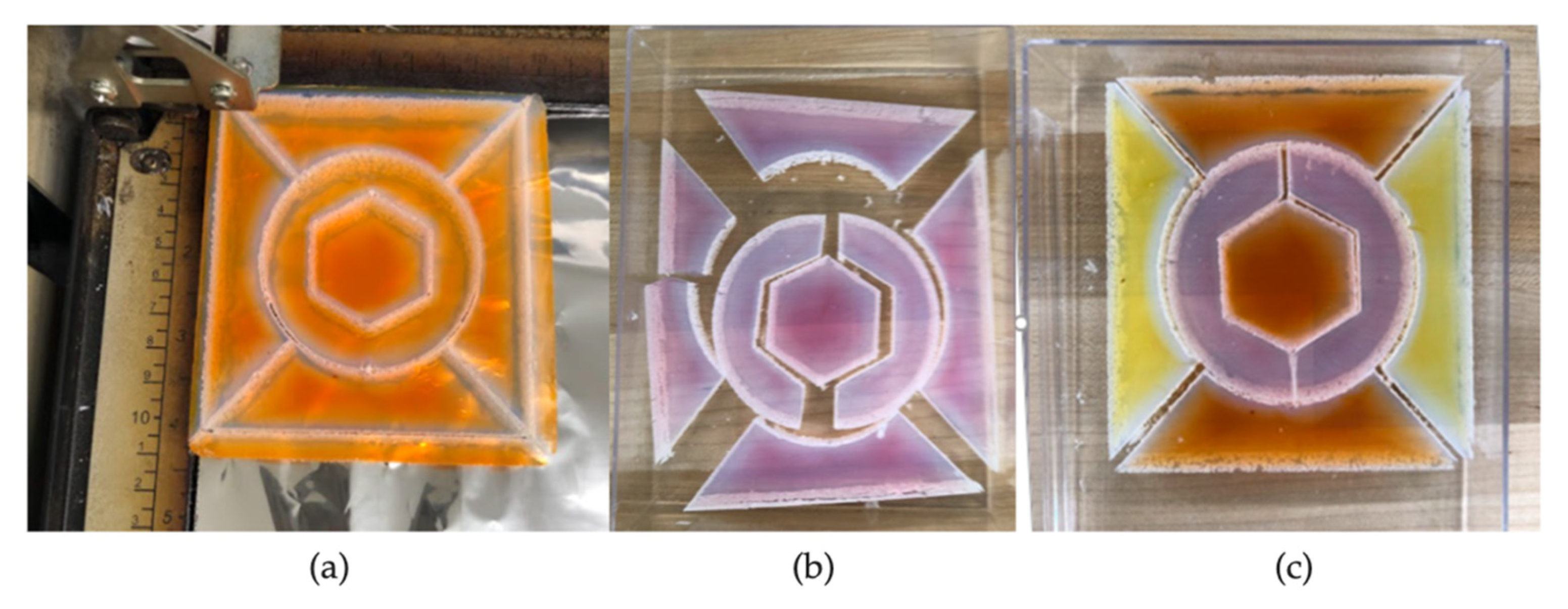
3.2.2. Use of Laser Etching and Cutting to Enhance Aesthetics

Another way to improve the appearance of the aerogel is to add visual interest and simultaneously mask defects by etching designs (patterns, text, photographs, etc.) onto the surface of the aerogel, as described in [43,44,45]. Etching changes the surface of the monolith in an aesthetically pleasing way without compromising the overall structural integrity of the aerogel monolith. The viewer’s eye is drawn to the pattern rather than any surface flaws. Images of different approaches that can be used are shown in Figure 10.
Here, we demonstrate that etching intricate patterns onto thin aerogel monoliths can be accomplished while maintaining the overall structure of the monolith. Tiles of 5 × 5 × 0.5 cm aerogel were laser-cut (speed 40%, power 100%, frequency 2500 Hz) from a larger monolith and then designs were etched onto them (speed 30%, power 50%, frequency 2500 Hz). The results are shown in Figure 11.
Samples can also be cut into shapes and arranged into interesting patterns [45]. To date, we have taken the approach of making mosaic- and stained-glass-window-like designs. In these aesthetic designs, seams between pieces and irregularities in color or pattern can be viewed as design features rather than flaws. Moreover, when looking through a mosaic- or stained-glass-style window, one does not expect to have an undistorted view.
Figure 12 shows the process for preparing a mosaic-style design, as described in [45]. In Figure 12a, a 1.5 cm thick 10 Rhodamine 6G aerogel monolith is shown in place on the platform of the laser cutter immediately after a pattern has been cut. Figure 12b shows a Rhodamine B aerogel after separating the cut pieces. Laser-cut edges appear white because of the scatter of light from the rough surfaces. Note that some bleaching of the dye (presumably due to thermal degradation) is observed along the laser-cut edges. Figure 12c shows a reconstructed aerogel monolith pattern, suitable for sandwiching between glass or polycarbonate panes to make a mosaic-style window.
Figure 13 shows the monoliths cut (20% speed, 50% power) and etched (10% speed, 20% power) from 0.5 cm thick aerogel monoliths for a prototype stained-glass-like design that could be incorporated into a glazing unit. At these settings, more bleaching was observed for the monoliths containing Fluorescein and Rhodamine 6G than for the one containing Rhodamine B. Etching and cutting parameters can be adjusted to minimize the bleaching (note the lack of visible bleaching in the Fluorescein-containing etched monolith in Figure 10f). Alternately, the bleaching effect can be viewed as part of the design.
Laser-cut edges are rough [44,45] and can be pressed together under mild compression to eliminate thermal gaps between pieces, resulting in a design that has comparable thermal properties to intact aerogel monoliths. This is in stark contrast to traditional stained-glass windows, which are constructed from individual glass pieces connected by metal and are, therefore, poorly insulative.

3.3. Approaches to Construction of Aerogel Window Prototypes

3.3.1. Scaled-Up Glazing Units

Although the RSCE method employed in our laboratory is scalable [27], the maximum achievable monolith size depends on the size of the hot press employed [36]. With our laboratory-scale press, we are unable to fabricate monoliths of the size required for typical glazing units. Consequently, we have taken the approach of preparing small prototypes by tiling individual monoliths to yield suitable insulated glass units (IGUs) for testing.
While the aerogel IGU prototype prepared using 1.27 cm thick aerogel monoliths (Figure 14) is not visually appealing, it performs well thermally. ASTM C518-17 (Standard Test Method for Steady State Thermal Transmission Properties by Means of the Heat Flow Meter Apparatus) results indicate that the IGU has an average thermal resistance of 1.11 m2K/W (corresponding to an average U-value of 0.9 W/m2K). This result is in line with the thermal data for aerogel-based glazing systems compiled by Buratti et al., which show U-values ranging from about 0.6 to 1.1 W/m2K for glazing systems that are approximately 25 mm thick [6]. However, haze values are high and transmission levels are low: ASTM D1003-13 Haze test results show that the IGU has haze values of 15.67 to 21.68 and ASTM D1003-13 Total Transmission results yield average total transmittance values between 54.8 and 60.5.
The aerogel IGU prototype prepared using thin monoliths (Figure 15) also performs well thermally. ASTM C518-17 results indicate that the IGU has an average thermal resistance of 0.39 m2K/W (corresponding to an average U-value of 2.56 W/m2K). There is no reported data in the literature for glazing systems made from thin (<5 mm) aerogels. However, the thermal resistance is lower than that of the thicker aerogel prototype (as expected, due to the difference in thickness of the insulating layer of material). Additional insulating ability could be achieved by reducing airspaces between the monoliths or employing a design involving spacers to allow the aerogel to be separated from the glass by a layer of air on one or both sides.
ASTM optical characterization was not performed on this sample. However, as can be seen from the spectral data in Figure 5 and the photographs in Figure 14 and Figure 15, the light transmittance of prototypes prepared with thinner monoliths is higher than for thicker aerogels prepared via a comparable process.
In fabricating these IGUs, the focus was on preparing a prototype with minimal thermal bridging rather than preparing an aesthetically pleasing glazing unit. Minor surface imperfections and differences in optical clarity from one monolith to another were not of concern, since they were not expected to have an impact on the thermal properties of the IGU.

3.3.2. Aesthetically Enhanced Glazing Unit Prototype

Here, we demonstrate that aesthetic improvements (described in Section 3.2) can be combined with simple window design features to yield an attractive glazing unit. A small IGU prototype was constructed from thin, optically transparent aerogel monolith tiles, some of which were prepared with dyes in the precursor mixture and/or etched with simple designs. The tiles were arranged in a 3-D printed frame and sandwiched between panes of glass, resulting in the prototype shown in Figure 16.
This prototype incorporates several improvements—highly transparent thin aerogel monoliths formed via RSCE in a three-piece mold, including colored monoliths of various hues due to different dyes and concentrations thereof, surface etching of text and designs, plus masking of seams between monoliths with the 3-D printed grid—to give the overall appearance of an aesthetically pleasing multi-pane window.

4. Conclusions

We have demonstrated a variety of approaches to preparing silica aerogel monoliths for incorporation into aesthetically pleasing and highly insulating glazing units. Experimental work has focused on monolithic silica aerogel prepared by a rapid supercritical extraction (RSCE) method, including: (1) process improvements that result in monoliths with higher visible light transmission; (2) innovative mold design for the preparation of uniform aerogel monoliths; (3) glazing designs that use thinner monoliths; and (4) the incorporation of artistic effects using dyes and laser etching to prepare glazing units with mosaic- or stained-glass-like patterns in which surface imperfections are perceived as features of the design rather than flaws.
As a general rule, visible light transmittance of >70% is desirable for window units, with single-pane windows having significantly higher transmittance and significantly lower thermal performance than double- or triple-pane IGUs [46]. Incorporation of silica aerogel monolith into a glazing unit will decrease visible transmittance while increasing thermal performance. The aerogel matrix scatters light, which is the fundamental reason that thick aerogel monoliths appear translucent rather than transparent, with a blue tint in reflection and a yellow–orange tint when transmittance is observed by eye. Chemical precursor recipes that yield more transparent aerogels can be employed; however, all other things being equal, the smaller path length associated with thinner monoliths results in lower scattering, higher transmittance, and less distortion of color and image.
For a given application, it may be necessary to compromise between optical performance and robustness. The speed of the RSCE method employed in this work (typically ~5–6 h from mixing chemicals to removing intact aerogels from the hot press) poses a significant advantage for scale-up to manufacturing but also provides relatively little time for wet gels to form stronger silica structures during aging. (The conventional supercritical CO2 extraction method involves solvent exchanges and, therefore, provides for additional aging time. However, the process takes a substantially longer time and generates more solvent waste, overall, than does RSCE.) Heat treatment was observed to improve both transparency and robustness.
There is also a trade-off between optical and thermal insulating performance. Although the prototype prepared using thin aerogel monoliths had impressive thermal performance, it is obvious that a thicker layer of aerogel will result in higher thermal and acoustic insulating ability. In ongoing work, we are investigating IGU designs that incorporate a thin aerogel monolith with air or other gas layers in the interspace between panes to improve insulating ability while retaining high optical transmittance. Evacuation, not employed in this study, would be expected to further improve thermal resistance [25,27,38].
In addition to preparing high-quality transparent silica aerogel, we have demonstrated how aesthetic designs, including the incorporation of dyes, laser cutting and laser etching tailored to individual applications, can be employed to mitigate the negative visual perception of plain aerogel monoliths.

5. Patents

Anderson, A.M.; Hajjaj, Z.; Mahony, M.K. Aerogel Mosaic-based Window System. United States Patent Application 20210363812 17/324514.
Gauthier, B.M.; Anderson, A.M.; Bakrania, S.; Mahony, M.K.; Bucinell, R.B. Method and Device for Fabricating Aerogels and Aerogel Monoliths Obtained Thereby. US Patent Numbers 7384988 B2 and 8080591.

Author Contributions

Conceptualization, M.K.C. and A.M.A.; methodology, M.K.C., A.M.A., S.T.M., Z.H. and M.C.; validation, M.K.C., A.M.A., S.T.M., Z.H. and M.C.; investigation, M.K.C., A.M.A., S.T.M., Z.H. and M.C.; resources, M.K.C. and A.M.A.; writing—original draft preparation, M.K.C. and A.M.A.; writing—review and editing, M.K.C., A.M.A., S.T.M., Z.H. and M.C.; visualization, M.K.C., A.M.A., S.T.M., Z.H. and M.C.; supervision, M.K.C. and A.M.A.; project administration, M.K.C. and A.M.A.; funding acquisition, M.K.C., A.M.A. and Z.H. All authors have read and agreed to the published version of the manuscript.

Funding

This material was based upon work funded by the National Science Foundation under Grants No. IIP-1415359 and IIP-2025800, and by the New York State Energy Research and Development Authority under Grant NYSERDA-87381. Additional funding was provided through a Union College Student Research Grant to Z.H. and the Union College Chemistry Department Kane Fund.

Data Availability Statement

The data presented in this study are contained within the article.

Acknowledgments

The authors acknowledge the contributions of Md Mainul Bhuiya, Avi Gajjar, Samuel Kleinberg, Luisa Posada, Joana Santos and Allison Stanec to the experimental work.

Conflicts of Interest

The authors declare no conflict of interest. The funders had no role in the design of the study; in the collection, analyses, or interpretation of data; in the writing of the manuscript, or in the decision to publish the results.

References

  1. Jelle, B.P.; Hynd, A.; Gustavsen, A.; Arasteh, D.; Goudey, H.; Hart, R. Fenestration of today and tomorrow: A state-of-the-art review and future research opportunities. Sol. Energy Mater. Sol. Cells 2012, 96, 1–28. [Google Scholar] [CrossRef] [Green Version]
  2. Buratti, C. (Ed.) Translucent Silica Aerogel: Properties, Preparation and Applications; Nova Science Publishers, Inc.: New York, NY, USA, 2019. [Google Scholar]
  3. Pajonk, G.M. Transparent silica aerogels. J. Non-Cryst. Solids 1998, 225, 307–314. [Google Scholar] [CrossRef]
  4. Strohbach, E. Optically Transparent, Thermally Insulating and Soundproofing (OTTIS) Aerogel for High-Efficiency Window Applications. Doctoral Thesis, Massachusetts Institute of Technology, Cambridge, MA, USA, February 2020. [Google Scholar]
  5. Wang, J.; Petit, D.; Ren, S. Transparent thermal insulation silica aerogels. Nanoscale Adv. 2020, 2, 5504. [Google Scholar] [CrossRef]
  6. Buratti, C.; Belloni, E.; Merli, F.; Zinzi, M. Aerogel glazing systems for building applications: A review. Energy Build. 2021, 231, 110587. [Google Scholar] [CrossRef]
  7. Aegerter, M.A.; Leventis, N.; Koebel, M.M. (Eds.) Aerogels Handbook; Springer: New York, NY, USA, 2011. [Google Scholar]
  8. Aegerter, M.A.; Leventis, N.; Koebel, M.; Steiner, S.A., III (Eds.) Springer Handbook of Aerogels; Springer Nature: Cham, Switzerland, 2022. [Google Scholar]
  9. Bisson, A.; Rigacci, A.; Lecomte, D.; Rodier, E.; Achard, P. Drying of silica gels to obtain aerogels: Phenomenology and basic techniques. Dry. Technol. 2003, 21, 593–628. [Google Scholar] [CrossRef]
  10. Cabot Aerogel Particles. Available online: https://www.cabotcorp.com/solutions/products-plus/aerogel/particles (accessed on 25 February 2022).
  11. Wittwer, V. Development of Aerogel Windows. J. Non-Cryst. Solids 1992, 145, 233–236. [Google Scholar] [CrossRef]
  12. Buratti, C.; Moretti, E. Experimental performance evaluation of aerogel glazing systems. Appl. Energy 2012, 97, 430–437. [Google Scholar] [CrossRef]
  13. Buratti, C.; Moretti, E. Glazing systems with silica aerogel for energy savings in buildings. Appl. Energy 2012, 98, 396–403. [Google Scholar] [CrossRef]
  14. Cotana, F.; Pisello, A.L.; Moretti, E.; Buratti, C. Multipurpose characterization of glazing systems with silica aerogel: In-field experimental analysis of thermal-energy, lighting and acoustic performance. Build. Environ. 2014, 81, 92–102. [Google Scholar] [CrossRef]
  15. Gao, T.; Jelle, B.P.; Ihara, T.; Gustavsen, A. Insulating glazing units with silica aerogel granules: The impact of particle size. Appl. Energy 2014, 128, 27–34. [Google Scholar] [CrossRef]
  16. Garnier, C.; Muneer, T.; McCauley, L. Super insulated aerogel windows: Impact on daylighting and thermal performance. Build. Environ. 2015, 94, 231–238. [Google Scholar] [CrossRef]
  17. Huang, Y.; Niu, J. Applications of super-insulating translucent silica aerogel glazing system on commercial building envelope of humid subtropical climates—Impact on space cooling load. Energy 2015, 83, 316–325. [Google Scholar] [CrossRef]
  18. Ihara, T.; Gao, T.; Gyrnning, S.; Jelle, B.P.; Gustavsen, A. Aerogel granulate glazing facades and their application potential from an energy saving perspective. Appl. Energy 2015, 142, 179–181. [Google Scholar] [CrossRef]
  19. Mujeebu, M.A.; Ashraf, N.; Alsuwayigh, A. Energy performance and economic viability of nano aerogel glazing and nano vacuum insulation panel in multi-story office building. Energy 2016, 113, 949–956. [Google Scholar] [CrossRef]
  20. Berardi, U. The benefits of using aerogel-enhanced systems in building retrofits. Energy Procedia 2017, 134, 626–635. [Google Scholar] [CrossRef]
  21. Rubin, M.; Lampert, C.M. Transparent silica aerogels for window insulation. Sol. Energy Mater. 1983, 7, 393–400. [Google Scholar] [CrossRef]
  22. Duer, K.; Svendsen, S. Monolithic silica aerogel in superinsulating glazings. Sol. Energy 1998, 63, 259–267. [Google Scholar] [CrossRef]
  23. Jensen, K.L.; Shultz, J.M.; Kristiansen, F.H. Development of windows based on highly insulating aerogel glazings. J. Non-Cryst. Solids 2004, 350, 351–357. [Google Scholar] [CrossRef]
  24. Shultz, J.M.; Jensen, K.L.; Kristiansen, F.H. Super insulating aerogel glazing. Sol. Mater. Sol Cells 2005, 89, 275–285. [Google Scholar] [CrossRef]
  25. Schultz, J.M.; Jensen, K.I. Evacuated aerogel glazings. Vacuum 2008, 82, 723–729. [Google Scholar] [CrossRef]
  26. Berardi, U. The development of a monolithic aerogel glazed window for an energy retrofitting project. Appl. Energy 2015, 154, 603–615. [Google Scholar] [CrossRef]
  27. Bhuiya, M.M.H.; Anderson, A.M.; Carroll, M.K.; Bruno, B.A.; Ventrella, J.L.; Silberman, B.; Keramati, B. Preparation of monolithic silica aerogel for fenestration applications: Scaling up, reducing cycle time and improving performance. Ind. Eng. Chem. Res. 2016, 55, 6971–6981. [Google Scholar] [CrossRef]
  28. Merli, F.; Anderson, A.M.; Carroll, M.K.; Buratti, C. Acoustic measurements on monolithic aerogel samples and application of the selected solutions to standard window systems. Appl. Acoust. 2018, 142, 123–131. [Google Scholar] [CrossRef]
  29. Zinzi, M.; Rossi, G.; Anderson, A.M.; Carroll, M.K.; Moretti, E.; Buratti, C. Optical and visual experimental characterization of a glazing system with monolithic silica aerogel. Sol. Energy 2019, 183, 30–39. [Google Scholar] [CrossRef]
  30. Buratti, C.; Moretti, E.; Belloni, E.; Zinzi, M. Experimental and numerical energy assessment of a monolithic aerogel glazing unit for building applications. Appl. Sci. 2019, 9, 5473. [Google Scholar] [CrossRef] [Green Version]
  31. Golder, S.; Narayanan, R.; Hossain, M.R.; Islam, M.R. Experimental and CFD investigation on the application for aerogel insulation in buildings. Energies 2021, 14, 3310. [Google Scholar] [CrossRef]
  32. SunThru LLC. Available online: https://www.sunthru.biz/ (accessed on 25 February 2022).
  33. AeroShield. Available online: https://www.aeroshield.tech/ (accessed on 25 February 2022).
  34. Tiem Factory Inc. Available online: https://www.tiem.jp/en/ (accessed on 25 February 2022).
  35. Gauthier, B.M.; Bakrania, S.D.; Anderson, A.M.; Carroll, M.K. A fast supercritical extraction technique for aerogel fabrication. J. Non-Cryst. Solids 2004, 350, 238–243. [Google Scholar] [CrossRef]
  36. Roth, T.B.; Anderson, A.M.; Carroll, M.K. Analysis of a rapid supercritical extraction aerogel fabrication process: Prediction of thermodynamic conditions during processing. J. Non-Cryst. Solids 2008, 354, 3685–3693. [Google Scholar] [CrossRef]
  37. Carroll, M.K.; Anderson, A.M.; Gorka, C.A. Preparing silica aerogel monoliths via a rapid supercritical extraction method. J. Vis. Exp. 2014, 84, e51421. [Google Scholar] [CrossRef] [Green Version]
  38. Büttner, B.; Nauschütz, J.; Heinemann, U.; Reichenauer, G.; Scherdel, C.; Weinläder, H.; Weismann, S.; Buck, D.; Beck, A. Evaculated Glazing with Silica Aerogel Spacers. In Proceedings of the EuroSun 2018: 12th International Conference on Solar Energy and Buildings Conference Proceedings, Rapperswil, Switzerland, 10–13 September 2018. [Google Scholar] [CrossRef]
  39. Rao, A.V.; Pajonk, G.M.; Parvathy, N.N. Effect of solvents and catalysts on monolithicity and physical properties of silica aerogels. J. Mater. Sci. 1994, 29, 1807–1817. [Google Scholar] [CrossRef]
  40. Tajiri, K.; Igarashi, K. The effect of the preparation conditions on the optical properties of transparent silica aerogels. Sol. Energy Mater. Sol. Cells 1998, 54, 189–195. [Google Scholar] [CrossRef]
  41. Athmuri, K.; Marinov, V.R. Optically transparent and structurally sound silica aerogels: Insights from a process study. Adv. Mater. Sci. 2012, 12, 5–16. [Google Scholar] [CrossRef] [Green Version]
  42. Strobach, E.; Bhatia, B.; Yang, S.; Zhao, L.; Wang, E.N. High temperature annealing for structural optimization of silica aerogels in solar thermal applications. J. Non-Cryst. Solids 2017, 462, 72–77. [Google Scholar] [CrossRef] [Green Version]
  43. Michaloudis, I.; Carroll, M.K.; Kupiec, S.; Cook, K.; Anderson, A.M. Facile method for surface etching of silica aerogel monoliths. J. Sol-Gel Sci. Technol. 2018, 87, 22–26. [Google Scholar] [CrossRef]
  44. Stanec, A.M.; Anderson, A.M.; Avanessian, C.; Carroll, M.K. Analysis and characterization of etched silica aerogels. J. Sol-Gel Sci. Technol. 2020, 94, 406–415. [Google Scholar] [CrossRef]
  45. Stanec, A.M.; Hajjaj, Z.; Carroll, M.; Anderson, A.M. Aesthetically enhanced silica aerogel via incorporation of etching and dyes. J. Vis. Exp. 2021, 169, e61986. [Google Scholar] [CrossRef] [PubMed]
  46. Anders, G.D. Windows and Glazing. Whole Building Design Guide. Available online: https://www.wbdg.org/resources/windows-and-glazing (accessed on 25 February 2022).
Figure 1. Schematic diagram of three-piece mold: (a) top piece; (b) middle piece; (c) bottom piece; and (d) assembly drawing.
Sustainability 14 02887 g001
Figure 2. Schematic flow chart illustrating the aesthetic aerogel window fabrication process and post-processing options.
Sustainability 14 02887 g002
Figure 3. Images of 13 × 12.5 × 0.5 cm silica aerogel monoliths fabricated from: (a) Recipe A-1; (b) Recipe A-2; (c) Recipe B-1; (d) Recipe B-2; (e) Recipe B-3.
Sustainability 14 02887 g003
Figure 4. Representative transmittance spectra for 5 mm thick silica aerogel samples made using each of the recipes listed in Table 1. The average %T from 380 to 720 nm for each sample is presented in the legend.
Sustainability 14 02887 g004
Figure 5. Representative transmittance spectra for 2.9 mm- and 5 mm thick aerogel samples made using Recipe B-2. For reference, these are compared to a 15 mm thick sample made using a variation of Recipe A-1. The average %T from 380 to 720 nm for each sample is presented in the legend.
Sustainability 14 02887 g005
Figure 6. Transmittance spectra for 2.9 mm thick silica aerogel sample before and after heat treatment at 425 °C for 45 min. The inset shows an image of the post-heat-treated sample placed on top of a piece of white paper, onto which has been photocopied a logo of the Union College Nott Memorial building.
Sustainability 14 02887 g006
Figure 7. Images of aerogel precursor solutions (top) and aerogels made from the solutions (bottom) containing: (a) Fluorescein; (b) Rhodamine B; and (c) Rhodamine 6G, each at three different concentrations; and (d) Brilliant Blue G250. Note: In views (a,b), the orders in which the solutions of different concentrations and aerogels prepared from those solutions were photographed were not the same.
Sustainability 14 02887 g007
Figure 8. Images of 10 × 10 × 1.5 cm silica aerogels made with (a) Fluorescein; (b) Rhodamine 6G; and (c) Rhodamine B.
Sustainability 14 02887 g008
Figure 9. Images of 5 × 5 × 0.5 cm pieces cut from 12 × 12 × 0.5 cm aerogel made from solutions containing: (a) Fluorescein; (b) Rhodamine 6G; (c) Rhodamine B; and (d) no dye. The aerogel samples are placed on top of a piece of white paper, onto which has been photocopied a logo of the Union College Nott Memorial building. Note that bleaching that occurred during the laser-cutting process is observed at the edges of the aerogels in views (a,b) and, to a lesser extent, (c).
Sustainability 14 02887 g009
Figure 10. Photographs of silica aerogel monoliths of various size and shape etched with designs (ac) and photographs (d,e) and a Fluorescein-containing monolithic aerogel etched with the Union College Minerva seal (f). This figure is adapted from Stanec, A.M.; Hajjaj, Z.; Carroll, M.K.; Anderson, A.M. Aesthetically enhanced silica aerogel via incorporation of laser etching and dyes. J. Vis. Exp. 2021, 169, e61986. doi:10.3791/61986 [45].
Sustainability 14 02887 g010
Figure 11. Photographs of 5 × 5 × 0.5 cm laser-cut and etched silica aerogel monoliths. These aerogel samples were photographed on top of black flocked paper.
Sustainability 14 02887 g011
Figure 12. Photographs showing preparation of aerogel mosaic-style pattern: (a) laser cutting of dye-doped aerogel monolith; (b) separation of laser-cut pieces of another aerogel monolith; and (c) assembly of pieces from different monoliths into one mosaic design for subsequent incorporation into a window prototype.
Sustainability 14 02887 g012
Figure 13. Stained-glass design prototype consisting of a combination of aerogel pieces laser-cut and -etched from different dye-containing 0.5 cm thick monoliths for subsequent incorporation into a window prototype. The length dimension at the bottom of the largest piece is 12.5 cm. Photographs were taken of the aerogel assembly on white (left) and black flocked (right) paper.
Sustainability 14 02887 g013
Figure 14. Prototype 30.5 × 30.5 × 2.5 cm aerogel IGU fabricated using 13 pieces of 1.27 cm thick silica aerogel monolith packaged between two 6.35 mm thick glass sheets.
Sustainability 14 02887 g014
Figure 15. Prototype 26.7 × 26.7 × 1.8 cm aerogel IGU fabricated using 0.5 cm thick silica aerogel monoliths packaged between two 6.35 mm thick glass sheets.
Sustainability 14 02887 g015
Figure 16. Photographs of 3 × 3 style window prototype on white (left) and black flocked (right) paper. The (middle) view shows that the view through the panes is clear, with minimal distortion. The prototype includes a variety of transparent plain and dye-containing aerogel monolith tiles, each of size 5 × 5 × 0.5 cm, including some with etched designs or text. Tiles were laser-cut from larger monoliths and placed in a 3-D printed frame, which was sandwiched between 3.18 mm thick panes of glass.
Sustainability 14 02887 g016
Table 1. Precursor recipes used for light transmittance study.
ChemicalRecipe A-1Recipe A-2
(2× Catalyst) 1
Recipe B-1Recipe B-2
(1.5× Catalyst) 2
Recipe B-3
(2× Catalyst) 2
TMOS (g)26.426.426.426.426.4
Methanol (g)66.166.157.157.157.1
DI water (g)10.910.111.710.910.2
1.5 M NH3 (µL)8161630150022503000
1 The amount of water is also adjusted to keep the same total volume of water as in Recipe A-1. 2 The amount of water is also adjusted to keep the same total volume of water as in Recipe B-1.
Table 2. Dyes used to fabricate colored aerogels.
DyeFluoresceinRhodamine 6GRhodamine B
Melting point (°C)315290210
Color in solutionYellowOrangePink
Mass % in methanol stock0.05%0.16%0.075%
Chemical structure Sustainability 14 02887 i001 Sustainability 14 02887 i002 Sustainability 14 02887 i003
Each precursor solution is mixed or sonicated for several minutes (until it is observed to be monophasic) prior to being poured into a mold for processing.
Table 3. RSCE processing parameters 1.
StepT
(°C)
Heat/Cool Rate
(°C/min)
Force
(kN)
Force Rate
(kN/min)
Dwell Time
(min)
Seal37--200–267--30
Heat2881–2.2200–267--30–55
Release288--14.4–13.25–15
Cool321–2.21----
1 Ranges are specified for some parameters to account for different mold sizes.
Publisher’s Note: MDPI stays neutral with regard to jurisdictional claims in published maps and institutional affiliations.

