
Suitability Zoning for Sustainable Drainage Systems (SuDSs): Application in a Basin in Southern Brazil


Abstract
1. Introduction
2. Materials and Methods
2.1. Materials and Data Sources
- topographic map from the Geographical and Cartographic Institute of São Paulo at a 1:10,000 scale;
- aerial photographs at the 1:8000, 1:25,000, and 1:60,000 scales;
- IKONOS satellite images;
- mechanical–manual augers;
- double-ring infiltrometers;
- PVC samplers; and
- laboratory equipment for the geological and geotechnical characterization of geological materials.
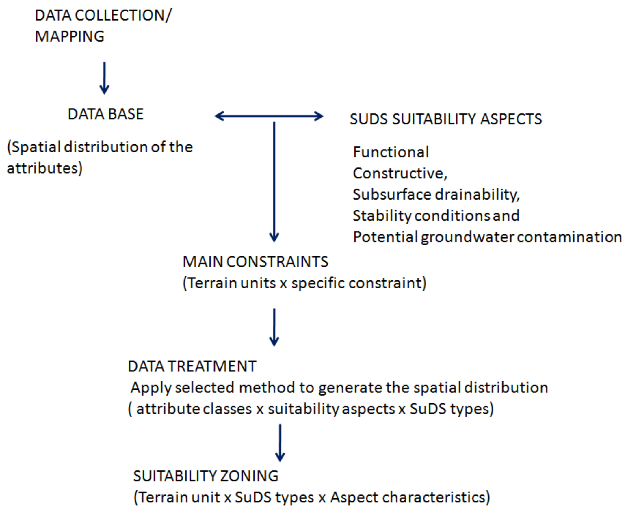
2.2. Development of the Procedure
2.3. Application of the Proposed Procedure
3. Results
3.1. Characterization of the Area
3.2. Analyses
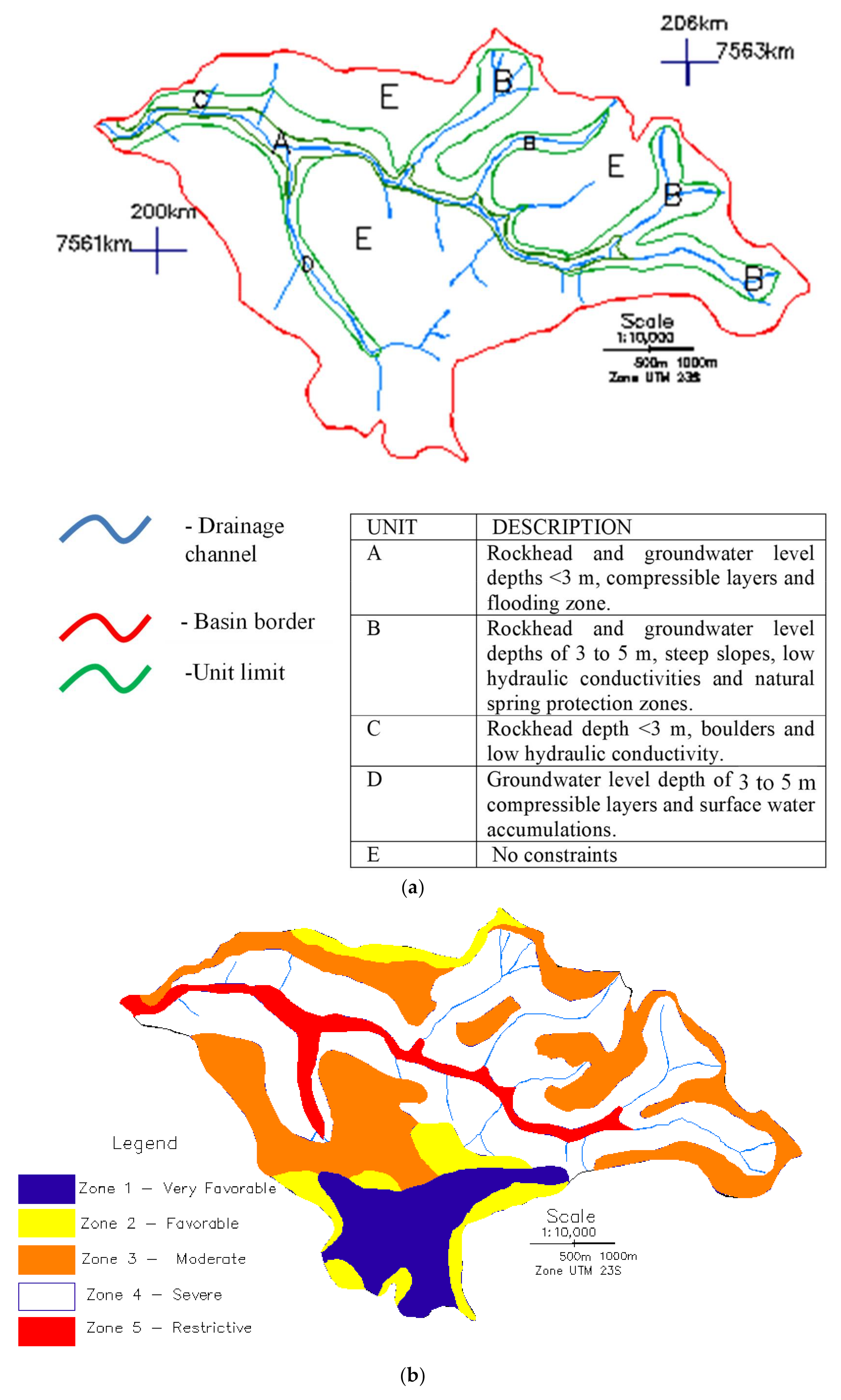
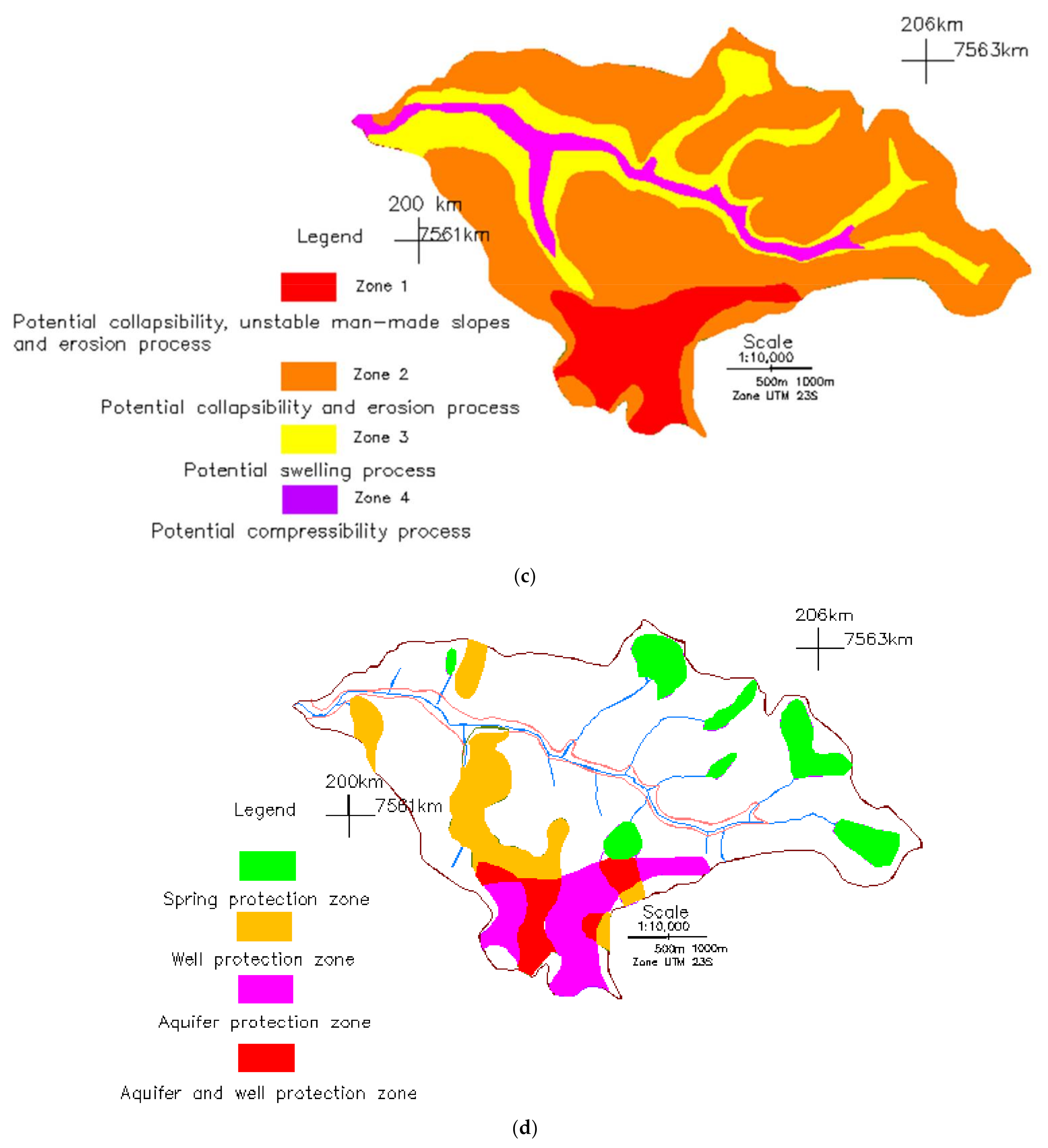
3.3. Zoning
- UNIT 1
- UNIT 2
- UNIT 3
- UNIT 4
- UNIT 5
4. Discussion
5. Conclusions
Supplementary Materials
Author Contributions
Funding
Data Availability Statement
Conflicts of Interest
References
- Sharma, S. Geological Behaviours in Urban Areas for Surface Runoff and Recharge. Open J. Soil Sci. 2017, 7, 181–201. [Google Scholar] [CrossRef][Green Version]
- Andersen, T. Detailed Geophysical Mapping and Hydrogeological Characterisation of the Subsurface for Optimal Placement of Infiltration-Based Sustainable Urban Drainage Systems. Geosciences 2020, 10, 446. [Google Scholar] [CrossRef]
- Zuquette, L.; Failache, M.; Barbassa, A. Assessment of Depressional Wetland Degradation, Spatial Distribution, and Geological Aspects in Southern Brazil. Geosciences 2020, 10, 296. [Google Scholar] [CrossRef]
- Coulthard, T.; Frostlick, L. The Hull floods of 2007: Implications for the governance and management of urban drainage systems. J. Flood Risk Manag. 2010, 3, 223–231. [Google Scholar] [CrossRef]
- Jacobson, C.R. Identification and quantification of the hydrological impacts of imperviousness in urban catchments: A review. J. Environ. Manag. 2011, 92, 1438–1448. [Google Scholar] [CrossRef] [PubMed]
- Kazmierczak, A.; Cavan, G. Surface Water Flooding Risk to Urban Communities: Analysis of Vulnerability, Hazard and Exposure. Landsc. Urban Plan. 2011, 103, 185–197. [Google Scholar] [CrossRef]
- Rotta, C.M.D.S.; Zuquette, L.V. Assessment of environmental degradation due to anthropogenic processes based on critical zones: A study in a basin in southern Brazil. Environ. Earth Sci. 2021, 80, 1–21. [Google Scholar] [CrossRef]
- Butler, D.; Parkinson, J. Towards sustainable urban drainage. Water Sci. Technol. 1997, 35, 53–63. [Google Scholar] [CrossRef]
- Martin, P. Sustainable Urban Drainage Systems-Design Manual for England and Wales; CIRIA: London, UK, 2000; pp. 1–124. [Google Scholar]
- Martin., P.; Turner, B.; Waddington, K. Sustainable Urban Drainage Systems-Design Manual for Scotland and Northern Ireland; CIRIA: London, UK, 2000; pp. 1–124. [Google Scholar]
- CIRIA. SUDS Techniques. Available online: http://www.ciria.org/suds/suds_techniques.htm (accessed on 10 December 2020).
- Charlesworth, S.M.; Harker, E.; Rickard, S.A. Review of sustainable drainage systems (SuDS): A soft option for hard drainage questions? Geography 2003, 88, 99–107. [Google Scholar]
- Ellis, J.B.; Deutsch, J.C.; Mouchel, J.M.; Scholes, L.; Revittm, D. Multicriteria decision approaches to support sustainable drainage options for the treatment of highway and urban runoff. Sci. Total Environ. 2004, 334, 251–260. [Google Scholar] [CrossRef]
- Dearden, R.; Price, S. A national suitability dataset for infiltration-based sustainable drainage systems. In Eleventh International Conference on Computing and Control for the Water Industry; Savic, D., Kapelan, Z., Butler, D., Eds.; Centre for Water Systems, University of Exeter: Exeter, UK, 2011; pp. 253–258. [Google Scholar]
- Dearden, R.A.; Price, S.J. A proposed decision-making framework for a national infiltration SuDS map. Manag. Environ. Qual. Int. J. 2012, 23, 478–485. [Google Scholar] [CrossRef]
- Dearden, R.A.; Marchant, A.; Royse, K. Development of a suitability map for infiltration sustainable drainage systems (SuDS). Environ. Earth Sci. 2013, 70, 2587–2602. [Google Scholar] [CrossRef]
- Zhou, Q. A Review of Sustainable Urban Drainage Systems Considering the Climate Change and Urbanization Impacts. Water 2014, 6, 976–992. [Google Scholar] [CrossRef]
- Bockhorn, B.; Klint, K.E.S.; Locatelli, L.; Park, Y.-J.; Binning, P.J.; Sudicky, E.; Jensen, M.B. Factors affecting the hydraulic performance of infiltration based SUDS in clay. Urban Water J. 2015, 14, 125–133. [Google Scholar] [CrossRef]
- Woods, B.W.; Wilson, S.; Udale-Clarke, H.; Illman, S.; Scott, T.; Ashley, R.; Kellagher, R. The SUDS Manual; CIRIA: London, UK, 2015. [Google Scholar]
- Dearden, R.A. User Guide for the Infiltration SuDS Map: Detailed; NERC: Nottingham, UK, 2011; p. 41. Available online: http://nora.nerc.ac.uk/id/eprint/16618/ (accessed on 25 October 2021).
- Charlesworth, S.; Warwick, F.; Lashford, C. Decision-Making and Sustainable Drainage: Design and Scale. Sustainability 2016, 8, 782. [Google Scholar] [CrossRef]
- Horton, B.; Digman, C.J.; Ashley, R.M.; Gill, E. BeST (Benefits of SuDS Tool) Technical Guidance; CIRIA: London, UK, 2015. [Google Scholar]
- Dearden, R.A. User Guide for the Infiltration SuDS Map: Overview. British Geological Survey Open Report; CIRIA: London, UK, 2012; p. 31. [Google Scholar]
- Bregulla, J.; Powell, J.; Yu, C. A Simple Guide to Sustainable Drainage Systems for Housing. NHBC Foundation. 2010. Available online: http://www.observatorio2030.com/sites/default/files/2019-11/GU_116_2010_GB_52_A%20simple%20guide%20to%20Sustainable%20Drainage%20Systems%20for%20housing.pdf (accessed on 15 February 2020).
- Essex County Council (ECC) (2014) Sustainable Drainage Systems Design Guide. Available online: https://cbccrmdata.blob.core.windows.net/noteattachment/suds%20design%20guide.pdf.pdf (accessed on 15 February 2020).
- CIRIA. West of England Sustainable Drainage Developer Guide Section; CIRIA: London, UK, 2015. Available online: https://www.bristol.gov.uk/documents/20182/34524/West+of+England+sustainable+drainage+developer+guide+section+1/864fe0d2-45bf-4240-95e2-a9d1962a0df9 (accessed on 25 February 2020).
- CIRIA. SuDS in London-A Guide; CIRIA: London, UK, 2016. Available online: http://content.tfl.gov.uk/sustainable-urban-drainage-november-2016.pdf (accessed on 20 February 2020).
- Staffordshire County Council. Sustainable Drainage Systems (SuDS) Handbook; Arcadis Consulting: Stanfordshire, UK, 2017. Available online: https://www.staffordshire.gov.uk/environment/Flood-Risk-Management/Documents/SuDS-Handbook.pdf (accessed on 13 March 2020).
- Hockenhull, J. Sustainable Drainage Systems (SuDS) Handbook; Arcadis Consulting: Herefordshire, UK, 2018. Available online: https://www.herefordshire.gov.uk/downloads/file/14026/sustainable-drainage-systems-handbook (accessed on 15 February 2020).
- Gibson, C. Sustainable Drainage Systems (SuDS) Handbook; Arcadis Consulting: London, UK, 2019. [Google Scholar]
- Andrés-Doménech, I.; Anta, J.; Perales-Momparler, S.; Rodriguez-Hernandez, J. Sustainable Urban Drainage Systems in Spain: A Diagnosis. Sustainability 2021, 13, 2791. [Google Scholar] [CrossRef]
- Archer, N.A.L.; Bell, R.A.; Butcher, A.S.; Bricker, S.H. Infiltration efficiency and subsurface water processes of a sustainable drainage system and consequences to flood management. J. Flood Risk Manag. 2020, 13, e12629. [Google Scholar] [CrossRef]
- Ferrans, P.; Torres, M.; Temprano, J.; Sanches, J. Sustainable Urban Drainage System (SUDS) modeling supporting decision-making: A systematic quantitative review. Sci. Total Environ. 2022, 806, 150447. [Google Scholar] [CrossRef]
- Gimenez-Maranges, M.; Breuste, J.; Hof, A. Sustainable Drainage Systems for transitioning to sustainable urban flood management in the European Union: A review. J. Clean. Prod. 2020, 255, 120191. [Google Scholar] [CrossRef]
- McClymont, K.; Cunha, D.G.F.; Maidment, C.; Ashagre, B.; Vasconcelos, A.F.; de Macedo, M.B.; dos Santos, M.F.N.; Gomes, M.N., Jr.; Mendiondo, E.M.; Barbassa, A.P.; et al. Towards urban resilience through Sustainable Drainage Systems: A multi-objective optimisation problem. J. Environ. Manag. 2020, 275, 111173. [Google Scholar] [CrossRef]
- Viavattene, C.; Ellis, J.B. The management of urban surface water flood risks: SUDS performance in flood reduction from extreme events. Water Sci. Technol. 2013, 67, 99–108. [Google Scholar] [CrossRef] [PubMed]
- Failache, M. Proposta de Procedimentos Para a Estimativa de Infiltração Potencial e do Escoamento superficial Hortoniano Potencial Baseada em Dados Geológicos, Geotécnicos, de Uso e Ocupação e Eventos de Chuva. Ph.D. Thesis, University of São Paulo, São Paulo, Brazil, 2018. [Google Scholar]
- Zuquette, L. Mapeamento Geotécnico Preliminar na Região de Sao Carlos. Master’s Thesis, Universidade de São Paulo, São Paulo, Brazil, 1981. [Google Scholar]
- Nishiyama, L. Mapeamento Geotécnico Preliminar da Quadricula de São Carlos–SP. Master’s Thesis, Universidade de São Paulo, São Paulo, Brazil, 1991. [Google Scholar]
- Aguiar, R.L. Mapeamento Geotécnico da Area de Expansão Urbana de São Carlos—SP. Master’s Thesis, Universidade de São Paulo, São Paulo, Brazil, 1989. [Google Scholar]
- Pons, N.A.D. Levantamento e Diagnóstico Geológico-Geotécnico de Areas Degradadas na Cidade de São Carlos–SP, Com Auxílio de Geoprocessamento. Ph.D. Thesis, Universidade de São Paulo, São Paulo, Brazil, 2006. [Google Scholar]
- Pons, N.A.D.; Pejon, O.J.; Zuquette, L.V. Use of geoprocessing in the study of land degradation in urban environments: The case of the city of São Carlos, state of São Paulo, Brazil. Environ. Geol. 2007, 53, 727–739. [Google Scholar] [CrossRef]
- Zuquette, L.V. Análise Crítica da Cartografia Geotécnica e Proposta Metodológica Para Condições Brasileiras. Ph.D. Thesis, Universidade de São Paulo, São Paulo, Brazil, 1987. [Google Scholar]
- Zuquette, L.V. A Importância do Mapeamento Geotécnico no Uso e Ocupação do Meio do Meio Físico: Fundamentos e Guia Para Elaboração. Free Teaching Thesis, Universidade de São Paulo, São Paulo, Brazil, 1993. [Google Scholar]
- Matula, M. Regional engineering geological evaluation for planning purposes. Bull. Int. Assoc. Eng. Geol. 1979, 19, 18–24. [Google Scholar] [CrossRef]
- Zuquette, L.V.; Pejon, O.J.; Collares, J.Q.D.S. Land degradation assessment based on environmental geoindicators in the Fortaleza metropolitan region, state of Ceará, Brazil. Environ. Earth Sci. 2003, 45, 408–425. [Google Scholar] [CrossRef]
- Rocha, L.C.C.; Zuquette, L.V. Evaluation of Zeolite as a Potential Reactive Medium in a Permeable Reactive Barrier (PRB): Batch and Column Studies. Geosciences 2020, 10, 59. [Google Scholar] [CrossRef]
- Rocha, L.C.C.; Zuquette, L.V. Estudo de meio reativo para barreiras reativas permeáveis (brp): Ensaios laboratoriais. Geosciences 2020, 39, 1025–1040. [Google Scholar] [CrossRef]
- Morgan, M.; Fenner, R. Spatial evaluation of the multiple benefits of sustainable drainage systems. In Proceedings of the Institution of Civil Engineers-Water Management; Thomas Telford Ltd.: London, UK, 2019; Volume 172, pp. 39–52. [Google Scholar] [CrossRef]
- Fengxiang, Q. Influencing Factors and Strategies for Sustainable Urban Drainage System. Civ. Eng. Res. J. 2018, 3, 555616. [Google Scholar] [CrossRef]
- Oladunjoye, O.A.; Proverbs, D.G.; Collins, B.; Xiao, H. A cost-benefit analysis model for the retrofit of sustainable urban drainage systems towards improved flood risk mitigation. Int. J. Build. Pathol. Adapt. 2019, 38, 423–439. [Google Scholar] [CrossRef]
- Lashford, C.; Charlesworth, S.; Warwick, F.; Blackett, M. Modelling the Role of SuDS Management Trains in Minimising Flood Risk, Using MicroDrainage. Water 2020, 12, 2559. [Google Scholar] [CrossRef]


| Component | Attributes | Parameters | Dimension | Categories | |||
|---|---|---|---|---|---|---|---|
| Favorable | Moderate | Severe | Restrictive | ||||
| Relief | Slope inclination | Classes/Categories | % | 1–10 | 10–20 | 20–30 | >30 |
| Channel frequency | Channel/km2 | <1 | 1–3 | 3–5 | >5 | ||
| Slope length | Measured between the watershed limit and the thalweg | m | >500 | 300–500 | 200–300 | <200 | |
| Unconsolidated materials | Regolith profile | Description based on variability | Homogenous and continuous | - | - | Heterogeneous and discontinuous | |
| Layer thickness | Surface layer | m | >5 | 3–5 | 2–3 | <2 | |
| Texture | Grain size distribution | % | Sandy with less than 30% of fines | Sandy with 30 and 50% of fines | Silt plus clay between 50 and 70% | Silt plus clay >70% | |
| Permeability | Hydraulic conductivity | cm/s | >10−3 | 10−3–10−4 | 10−4–10−5 | <10−5 | |
| Porosity | - | % | >50 | 45–50 | 40–45 | <40 | |
| Mineralogy | Clay minerals (categories to estimate the potential for swelling) | Mineral | No | Kaolinite, gibbsite, illites | Smectites, interstratified minerals <3% | Smectites, vermiculites, interstratified minerals | |
| Clay minerals (categories for estimating the magnitude of the retardation factor) | Mineral | Smectites, vermiculites, interstratified minerals | Smectites, interstratified minerals <3% | Kaolinite, gibbsite, illites | No | ||
| Reactive and soluble minerals | Mineral | No | No | Sulfides, carbonates <0.5% | Sulfides, carbonates | ||
| Boulders | - Size - Frequency - Depth | No | Small, few, shallow or on the ground surface | Large, few, shallow or on the ground surface | Many boulders with varying sizes and at varying depths | ||
| pH | - | 5–7.5 | 7.5–8.5 | >8.5 | |||
| Electrical conductivity | - | dS/m | <1 | 1–4 | 4–6 | >6 | |
| Exchangeable sodium percentage | - | % | <5 | 5–10 | 10–15 | >15 | |
| Organic material | - | % | >3 | 2–3 | 1–2 | <1 | |
| Bedrock | Lithotype | - | High porosity | Low porosity | |||
| Rockhead depth | - | m | >10 | 5–10 | 3–5 | <3 | |
| Mineralogy | Clay mineral | Kaolinite, gibbsite, | Illites | Smectites <3% | Smectites, vermiculites | ||
| Reactive and soluble minerals | No | No | Percentage <1% | Sulfides, carbonates | |||
| Permeability | Hydraulic conductivity | cm/s | >10−3 | 10−3–10−4 | 10−4–10−5 | <10−5 | |
| Fractures | Aperture | cm | 0.02–0.05 | >0.05 | 0.01–0.02 | <0.01 | |
| Frequency | Fractures/m | >3 | 2–3 | 1–2 | 1 | ||
| - | Jv (volumetric joint count) | >15 | 10 to 15 | 3 to 10 | <3 | ||
| Groundwater | Groundwater level/seasonality | - | m | >10 | 5–10 | 3–5 | <3 |
| Flow direction | Hydraulic gradient | >0.01 | 0.005–0.01 | 0.001–0.005 | <0.001 | ||
| pH | - | 5.5–7.5 | 7.5–8.5 | >8.5 | |||
| Electrical conductivity | - | dS/m | <0.5 | 0.5–3 | 3–5 | >5 | |
| Flooding due to groundwater level rising | Groundwater flooding (saturation excess overland flow) | Evidence/vestiges/presence of surface of hydric diffraction | - | No | No | Potential | Occur |
| Anthropogenic aspects | Made ground | Excavated geological materials, tailings and wastes deposited on the land surface | - | No | No | Occur | Occur |
| Worked ground | Excavated land for various purposes, such as aggregate sources | - | No | Abandoned quarries | Occur | Occur | |
| Infilled | Excavated and subsequently infilled places for other uses | - | No | Fill with geological materials | Fill using not hazardous materials | Fill with tailing, wastes and hazardous materials. | |
| Disturbed | Areas that, due to excavations for various purposes, in the shallow portions, suffered collapses | - | No | - | Occur | Occur | |
| Landscaped | Areas that have undergone modifications for different uses and that do not fit into the previous categories | - | No | Golf course, sportive areas, airports | Occur | Occur | |
| Hazard sources | Flooding | Evidence | - | No | No | Occur | Occur |
| Creep | Evidence | - | No | No | Occur | Occur | |
| Landslides | Evidence | - | No | No | Occur | Occur | |
| Collapsible geological materials | Porosity, texture, dry unit weight | - | No | Occur <2 m deep | Occur with depth up to 5 m | Occur with depth up to 10 m | |
| Compressibility | Organic layers, porous clayed layers | - | No | Occur <2 m | Occur in depth up to 5 m | Occur in depth up to 10 m | |
| Swelling | Clay minerals, smectite percentage | - | No | Occur <2 m | Occur in depth up to 5 m | Occur in depth up to 10 m | |
| Dispersivity | Exchangeable sodium percentage, electrical conductivity, texture | - | No | Occur <2 m | Occur in depth up to 5 m | Occur in depth up to 10 m | |
| Soluble geological materials | Soluble minerals, carbonates | - | No | No | Occur <1% | Occur | |
| Caves/sinks | Evidence | - | No | No | Occur | Occur | |
| Special aspects | Protection zones | Groundwater well | - | No | No | Occur | Occur |
| Natural springs | - | No | No | Occur | Occur | ||
| Lakes, reservoirs | - | No | No | Occur | Occur | ||
| Era | Period | Formation | Lithologies | Characteristics | Water Flow Type |
|---|---|---|---|---|---|
| Cenozoic | Paleocene/Eocene | Itaqueri | Moderate cemented sandstones, siltstones/claystones, conglomerates | These lithologies are in layers intercalated with different thicknesses. | The sandstones have good water storage conditions, and the flow is predominantly porous; however, the small thicknesses of the layers do not support high productivity of wells. |
| Mesozoic | Cretaceous | Serra Geral | Basalts | Layers of fractured basalts ranging from massive to those containing vesicular/amygdaloidal structures (dense basalts, vesicular–amygdaloidal basalts, and basaltic breccias). | Lithologies with fracture flow and predominance of horizontal flow due to lava interflow discontinuities. |
| Basalt intercalated with very cemented sandstone layers of the Botucatu Formation | Layers of sandstones of small thickness in the order of meters, variable continuity, with outcrops of sandstones and basalt in different sites in the main valley. | ||||
| Cretaceous/Jurassic | Botucatu | Very well-cemented sandstones | The sandstone package is usually associated with steep scarps, very fractured and with thicknesses less than 100 m. | The water flow is predominantly by vertical fractures. | |
| Very low to low cemented sandstones (friables) | The layer thicknesses can reach values higher than 150 m. | Porous water flow with high transmissivity. |
| Unit 1 (Layer Type/Limit Type between Layers) | Unit 2 | Unit 3 | Unit 4 | Unit 5 | Unit 6 |
|---|---|---|---|---|---|
| Sandy transported Distinct/wavy | Sandy transported Distinct/wavy | Sandy transported Distinct/wavy | Residual from Itaqueri Formation Diffuse/irregular | Clayey sand transported Distinct/wavy | Clay transported with boulders and rock blocks Diffuse/irregular or occluded |
| Residual from Itaqueri Formation Diffuse/irregular | Residual from Serra Geral Formation Diffuse/irregular | Residual from Botucatu Formation Distinct/wavy | Saprolite Diffuse/irregular or occluded | Residual from Serra Geral Formation Diffuse/irregular | Saprolite Diffuse/irregular or occluded |
| Saprolite Diffuse/irregular or occluded | Saprolite Diffuse/irregular or occluded | Saprolite Indistinct/irregular | Weathered rock | Saprolite Diffuse/irregular or occluded | Weathered rock |
| Weathered rock Rock | Weathered rock Rock | Weathered rock Rock | Rock | Weathered rock Rock | Rock |
| Unit 7 | Unit 8 | Unit 9 | Unit 10 | Unit 11 | |
| Residual from Serra Geral Formation Diffuse/irregular | Saprolite Diffuse/irregular or occluded | Residual from Botucatu Formation Distinct/wavy | Alluvial transported Indistinct/irregular | Sandy transported Distinct/wavy | |
| Saprolite Diffuse/irregular or occluded | Weathered rock | Saprolite Indistinct/irregular | Residual from Serra Geral Formation Diffuse/irregular | Residual from Itaqueri Formation Diffuse/irregular | |
| Weathered rock | Rock | Weathered rock | Saprolite Diffuse/irregular or occluded | Saprolite Diffuse/irregular or occluded | |
| Rock | Rock | Weathered rock Rock | Weathered rock Rock |
Publisher’s Note: MDPI stays neutral with regard to jurisdictional claims in published maps and institutional affiliations. |
© 2022 by the authors. Licensee MDPI, Basel, Switzerland. This article is an open access article distributed under the terms and conditions of the Creative Commons Attribution (CC BY) license (https://creativecommons.org/licenses/by/4.0/).
Share and Cite
Failache, M.; Pons, N.; Pejon, O.; Zuquette, L. Suitability Zoning for Sustainable Drainage Systems (SuDSs): Application in a Basin in Southern Brazil. Sustainability 2022, 14, 2577. https://doi.org/10.3390/su14052577
Failache M, Pons N, Pejon O, Zuquette L. Suitability Zoning for Sustainable Drainage Systems (SuDSs): Application in a Basin in Southern Brazil. Sustainability. 2022; 14(5):2577. https://doi.org/10.3390/su14052577
Chicago/Turabian StyleFailache, Moises, Nívea Pons, Osni Pejon, and Lázaro Zuquette. 2022. "Suitability Zoning for Sustainable Drainage Systems (SuDSs): Application in a Basin in Southern Brazil" Sustainability 14, no. 5: 2577. https://doi.org/10.3390/su14052577
APA StyleFailache, M., Pons, N., Pejon, O., & Zuquette, L. (2022). Suitability Zoning for Sustainable Drainage Systems (SuDSs): Application in a Basin in Southern Brazil. Sustainability, 14(5), 2577. https://doi.org/10.3390/su14052577