2. Literature Review
The researchers all over the world have made some achievements in the field of train operations in the stations. In the following, we try to give a brief review of the existing works from three perspectives. The first one is related to the works on determining the train routing into and out of the station, the second one is related to the works on selecting platform for trains in the station, and the third one is the researches concerned with the integrate selection of a platform and train’s path into and out of the station.
Trains run into and out of the station through the bottlenecks. The bottlenecks in the large railway passenger station are very complex where many frequent technical and shunting operations are performed over a long time. How to allocate suitable paths for trains running into and out of the bottlenecks is an important optimization problem in railway operation reality. Research related to this topic usually focus on balancing the use of turnout equipment. Zwaneveld et al. [
1] built the first node packing model to determine the train paths into and out of a station, and an improved branch and cut algorithm was designed to find an optimal solution. Zwaneveld et al. [
2] proposed a weighted node packing model, and several hierarchical objectives were considered in its model. Kroon et al. [
3] constructed a similar model as that of Zwaneveld et al. [
1], and proved that the node packing model is NP-complete once the train has more than three candidate routings. Lusby et al. [
4] built a set packing model and designed a branch-and-price algorithm to generate feasible routes dynamically. Shi [
5] proposed a network flow model and tight side optimization methods for the maximum parallel route and the maximum probability route, respectively, according to the sequence rules. Long [
6] built a nonlinear programming model and proposed a simulated annealing algorithm to find an optimal solution. D’Ariano [
7] illustrated a detailed model for conflict resolution in railway bottlenecks and analyzed different algorithms for resolving conflicts. Kang et al. [
8] proposed a simulated annealing heuristic algorithm with the goal of achieving the balanced occupation of station turnouts while minimizing the total occupation time cost of the station turnouts. Wu et al. [
9] developed a mean-variance optimization model based on Markowitz’s portfolio theory, and an efficient simulated annealing heuristic algorithm was designed to solve the resulting problem. Liu et al. [
10] developed an MINLP model to reallocate the tracks of trains at the stations in a real-time manner and the goal was to minimize average use time of groups of turnouts without changing the planned train times.
Selecting platforms for trains in the station is known as train platforming problem, which focuses on scheduling the train movements at the stations efficiently with fixed and slightly relaxed train arrival and departure times. This problem has attracted the attention of many researchers around the world. Cardillo et al. [
11], Billionnet et al. [
12], and Cornelsen et al. [
13] proposed graph colouring approaches for the train platforming problem. These studies focus on the stations which have only limited routing options to and from platforms. A conflict graph also forms the basis of graph colouring approaches; however, unlike the node packing formulations discussed in Kroon et al. [
3], the aim is to assign each node a colour such that no two adjacent nodes have the same colour. Carey et al. [
14] considered the problem of platforming trains at busy stations, and permitted deviations on the arrival and departure times of trains. A greedy heuristic was proposed according to the train dispatchers’ manual methods. Carey et al. [
15] further extended the work in Carey et al. [
14] by considering the train scheduling and platforming problems at multiple stations, and modified the algorithm of Carey et al. [
14] slightly to include some extra flexibility when resolving conflicts. Chakroborty et al. [
16] developed an MILP model for optimally allocating trains to the platform tracks, where the accurate train arrival times can only be available shortly before the train arrives at the station such that trains could be reassigned to different platforms.
In recent years, some researchers tried to determine a complete train route in the stations consisting of an inbound path, an outbound path and a platform. Caprara et al. [
17] presented a 0–1 quadratic programming model based on a pattern incompatibility graph. In particular, the quadratic term in the objective function was designed to consider the soft incompatibility costs between train paths. Corman et al. [
18] proposed a fast heuristic and a truncated branch and bound algorithm for computing train schedules and train rerouting, and realized the dynamic adjustment of station operation plans by adjusting train stop times, train speeds, entry orders and approach allocations. Ma et al. [
19] considered the restrictive relationship between station bottleneck sections and platform track, and established the train route allocation model under the condition of punctuality as well as the dynamic adjustment model considering the delay. Peng et al. [
20] built a model based on the comprehensive application of platform tracks and station bottleneck sections, so as to prepare an effective application adjustment plan of platform tracks quickly when encountering external interference. Gan [
21] established a comprehensive optimization model, which takes into account the fixed usage plan of arrival-departure tracks, the efficiency of technical operation and the stability of the passenger station operating plan.
Recently, some authors [
22,
23,
24] proposed studies in the field of operating variable configuration CRH in Chinese railway system. They analyzed the adaptability of variable configuration CRH from the aspects of line and station capacity utilization and passenger demand, and pointed out some relevant factors and conditions that should be possessed when the variable configuration CRH trains are put into operation. Jiang [
25] and Fu et al. [
26] further studied the impact of variable configuration CRH trains on the maintenance plan and EMU (Electric Multiple Unit) routing scheme after they are put into operation.
Based on the above analysis, the research on the influence of the combination and decomposition of variable configuration trains on the train route allocation problem is still insufficient, and integrated optimization of train routes into and out of station and the arrival-departure tracks needs to be clarified. Considering the combination and decomposition process of trains, a multi-objective model is constructed, which determines the reception and departure routes of trains at the railway station with limited infrastructure capacity according to the station yard layouts, train diagram and relevant technical operation time of the station. A solution algorithm framework using “constraint method” is designed and the software Gurobi is employed to solve the model considering mathematical optimization. The Pareto optimal solution set is obtained, which could be used for decision makers to choose a better comprehensive application scheme according to the actual operation situation on the site.
3. Problem Description
3.1. Description of Train Route Problem and Station Operation Process
The train routing problem can be regarded as one of the fundamental scheduling problems for railway companies, which can guide the usage of the receiving and departure routes of trains at the railway station with limited infrastructure capacity, given the station yard layouts, train diagram and correlative technical operation time of the station.
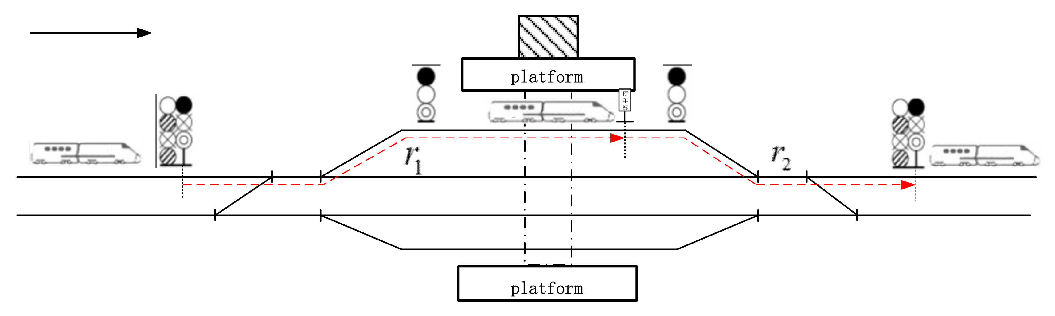
Train routing is implied as a section of line within the station occupied by the train when it departs, passes and turns around [
13]. The train routing defined in this paper is made up of the route in the station bottleneck sections and the occupied platform tracks at the railway station occupied by the movements of the trains. The train route can be further depicted vividly in
Figure 1 below.
The red dotted line is an example of the train route in the bottleneck section and the route on the platform tracks. The train stops on the platform track,
in
Figure 1 refers to the receiving routes, from the entry signal at the left bottleneck to the parking point of the platform track;
is the departure route, from the parking point on the platform track to the entry signal for reverse direction. It can be seen that once the route scheme is determined, the bottleneck section paths and the occupied platform tracks the information of the train receiving and departure can be deduced. Other types of routes can be analogized in turn. When trains operated between EMUdepot and railway station, the outbound and the inbound routes of those trains at this railway station are ending at or starting from the entry signals on the connecting lines between the rolling stock depot and the station.
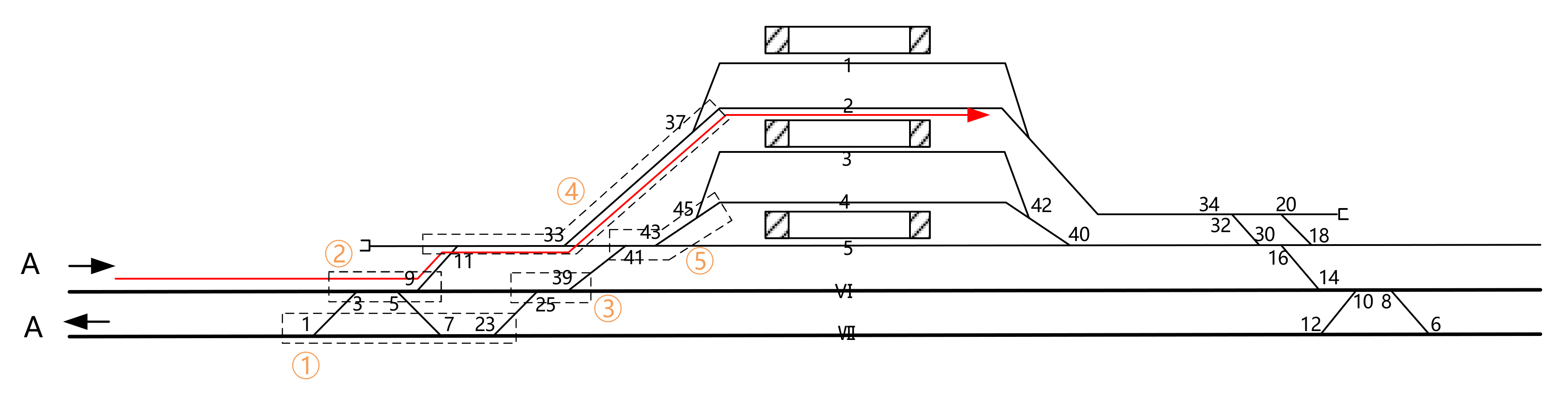
Based on the above analysis, the train receiving and departure routes can be represented by the combination of receiving direction, turnouts, platform tracks and departure direction. In order to simplify the calculation, the “coordinate calculation method” or the “parallel route method” is used to divide the turnouts into groups. Therefore, when describing the train routing, “turnout groups” rather than “turnouts” will be taken as the basic unit. As shown in
Figure 2, after dividing the turnouts into groups, one path in the bottleneck section from direction A can be generated, expressed as: receiving direction A → turnout group 2 → turnout group 4. By adding platform tracks that the bottleneck section paths may be connected, one receiving route could be created: receiving direction A → turnout group 2 → turnout group 4 → platform track 2. In addition, when different receiving routes pass through the same turnout group, it can be judged there is a conflict in “space” among different routes, and the resolution of conflict should be considered from the perspectives of “time” and “space”.
There is a one-to-one correspondence between the train routing and the train movements at the station. The train movements at the station mainly include receiving movement, departure movement, inbound and outbound movement and passing movement.
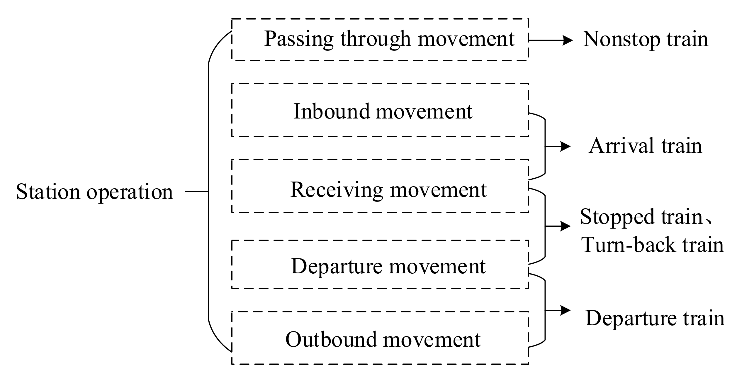
Hereinbefore, trains can pass through, terminate at, originate from, stop at or turn-back at one station. Different stop types of trains have different train movements (routes)—see
Figure 3. For example, one train which stops at a station has two movements, a receiving movement and departure movement; one train passing through a station without stop has a passing-through movement; one train originating from a station has an outbound movement and a departure movement; one train terminating at a station has an inbound movement and a receiving movement. Therefore, we analyze and model the “train movements at the station” as the research object rather than the “train”.
3.2. Analysis on Technical Operation Time of Train in Station
According to the analysis of train movements and its occupation in the station bottleneck sections and the platform tracks, five stop types of trains can be grouped into two types: trains that stop at the station and trains that pass through the station. In order to analyze and explain the occupation times of the station infrastructure when receiving and departing various types of trains, the symbols are listed in
Table 1.
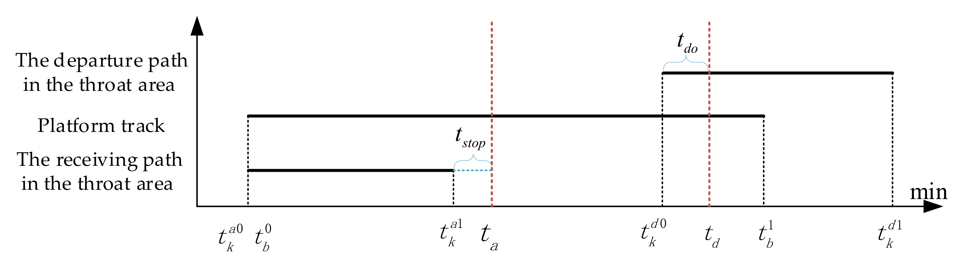
The time chart of the two types of trains occupying equipment at the station is different. The occupation of tracks mainly occurs in the throat area of the departure route.
When it is the passing-through train, the operator needs to prepare the receiving and departure route for the train at the same time, and block the route. When it is a stopped train, the operator can prepare the receiving and departure route for the train separately, as shown in
Figure 4 and
Figure 5.
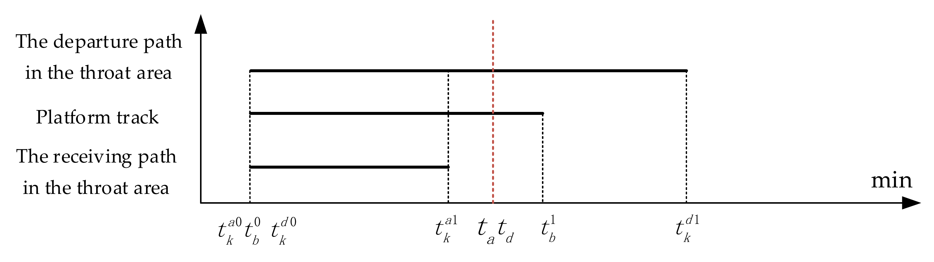
Furthermore, various occupation times in the throat area and platform tracks are analyzed, and the minimum security interval time for trains occupied the same equipment is deduced to meet the safety requirements. The dwell time of the train can be expressed by . Time duration for handling departure route is equal to . The occupation time of platform tracks in the station is , the occupation time of station bottleneck sections in receiving route and departure route can be, respectively, expressed by .
The minimum safety interval between every two trains occupying the same platform track can be described as follows: when the front train clears the platform track at stamp time , the following train is at the position close to the arrival signal in the receiving route, and the receiving route is starting to be ready for allocating arrival trains at the time . The theoretical minimum security interval time of the two successive arriving trains in the same direction occupying the same platform tracks is equal to .
3.3. Analysis of Variable Train Configuration
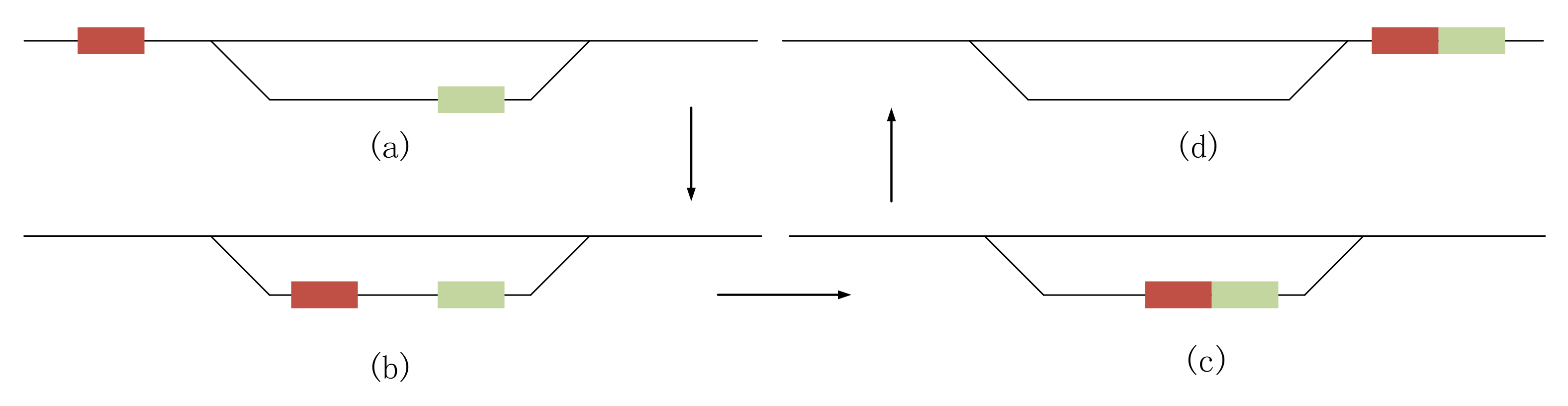
The combination movements of trains at the station can be summarized as the following technical movements: the front train (see the green block in
Figure 6) is allocated to the platform track with facilities for train combination operation, and the corresponding train control on-board equipment status is changed to standby mode, then the receiving route that connected the same platform track is prepared for the rear train (see red block in
Figure 6). When the following train arrives at the platform track and stops stably, the train’s control onboard equipment of the rear train is shifted to shunting mode, and connected with the front train slowly. The combination process is shown in
Figure 6, which follows the sequence of a → b → c → d. During train disassembly, the grouping train with large units shall be allocated to the platform track with disassembly facilities in the station. When the train arrives at the platform track and stops stably, the train can be disassembled only after the on-board equipment state of the train is converted to the shunting mode. Under the requirement of minimum safety interval, prepare corresponding departure routes should be prepared for the trains with short units, respectively. The specific schematic flow is opposite to the train combination process, which is d → c → b → a.
The variable configuration has a certain impact on the selection of train route, and further increase the complexity of station operation problem. For a new train composed of front train and rear train, the manager only needs to prepare one departure route for it, which can save one departure route compared with the case of no combination operation. For two new trains split by a grouped train, the manager needs to prepare two departure routes for the two new trains. It is thereby to prepare one more departure route than the case of no decomposition operation. However, whether to combine two trains or split one train to several depends on station capacity, the station layout and train diagram, which makes the operation problem more sophisticated.
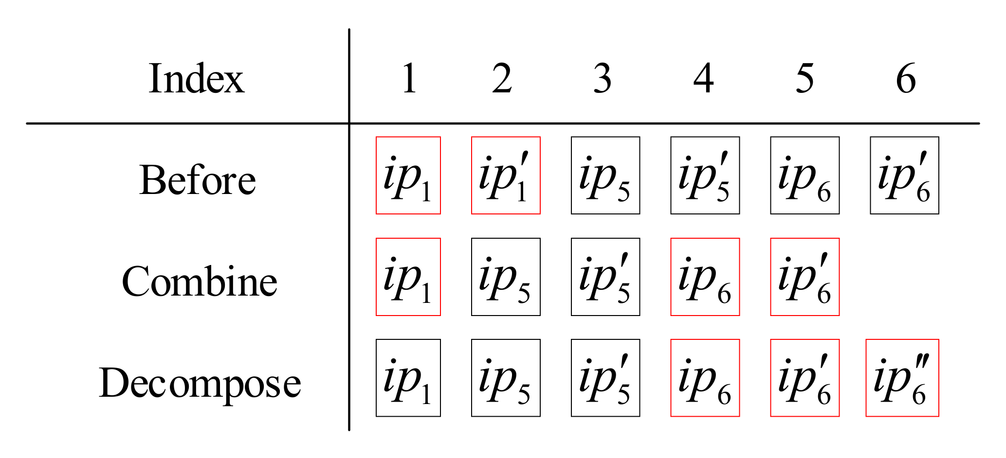
In the actual operation process, we first generate the operation process set (such as the arrival movement, departure movement et al.) according to all arriving trains at the station, and then eliminate the departure movement of the front train in a combined train, add a departure movement for the train that is disassembled.
Figure 7 shows the changes of the operation process after train combination and decomposition. Assuming that the train
and train
are combined at the station and the train
is disassembled at the same station, and the two small trains split by train
have the same destination as the train
,
and
are the arrival movement and departure movement of train
,
and
are the arrival and departure movement of train
. As the train
and the train
are combined into a new train in which the train
is in the front. In this case, the departure movement of
i.e.,
is canceled;
and
are the arrival and departure movement of train
when the train
will split into two small trains in the track, a new departure movement
should be increased.
Based on the above analysis, according to the characteristics of train combination and decomposition and various constraints on train route assignment, a novel mathematical model is constructed as hereinafter.
4. Modeling Work
4.1. Model Assumptions
- (1)
Highspeed railway station yard layout, train operation direction, train type, arrival and departure time are given in advance.
- (2)
Relevant facilities and infrastructure of the station have the ability to carry out the train combination and disassembly, and the train number to be combined and disassembled has been given in advance.
- (3)
All facilities that are occupied by one throat route in the station are unlocked at the same time.
4.2. Variable and Parameter Definition
The set of trains that stop at or pass through one high-speed railway station is denoted as
, where
n is the total number of trains in the set. According to the description in
Section 3, a train route can be decomposed into several train movements, and “train movements” are the research object rather than “trains”. We set
as a collection of train movements, where
is the index of train movements. The elements in the train movement set will be reordered according to the sequence in which the train movement process occupies the tracks, and elements with the same starting time shall be arranged according to the train numbers that have been served, then a new train movement set is generated,
.
The set of platform tracks of high-speed railway stations is expressed by
. The route set in the bottleneck sections of the station is
, where
and
are the total number of the platform tracks and the total number of routes in bottleneck sections of the station, respectively. In addition, the input parameters and the decision variables of this study are describled in
Table 2 and
Table 3 in detail.
4.3. Model Establishment
The multi-objective function of the train routing model includes two parts: The platform track assignment costs and throat route assignment costs, which are represented by
. Balanced utilization cost of platform tracks is represented by
, which is calculated by summing up the variance of the occupied time of all platform tracks. The smaller the variance value, the more balanced the occupation of tracks.
In the constraint conditions, Equation (3) indicates that a train movement can only occupy one throat route and one platform track. Equation (4) indicates that when the train movement is assigned to platform track , a throat route connected to the track shall also be assigned to the train movement .
Equation (5) indicates that if the train movement is assigned to a throat route r, a platform track connected to the throat route shall also be arranged for the train movement .
Equations (6) and (7) ensure that any train movement can only select routes in the given throat route set and the platform track set.
Equation (8) states that the different train movements and from the same train should occupy the same platform track.
Equation (9) indicates that if two trains have a combination relationship, their train movement in the platform track also has a combination relationship. Equation (10) indicates that if two adjacent train movements come from two different trains, they shall meet the minimum safety interval when they occupy the same platform track. Equation (11) specifies that when two throat routes with mutual interference, it is necessary to satisfy the minimum safety interval when any two train movements occupy them, respectively. Equation (12) is a nonlinear constraint, which means if the two train movements carry out a combined operation on track , no other train movement can occupy track between the two train movements.
Equation (12) is a nonlinear constraint. Considering the actual situation, when trains are combined in a platform track, the arrival interval time between the front train and the following train is added into the end time of the front train occupying the platform track, that is, the end time of the front train arrival movement occupying the platform track is extended to the , which is start time of train movement occupying platform track . In this way, the platform track with combination operation will always be occupied after the front train is allocated. At this time, other trains will not be able to access the platform track, and the following train for combination can be allowed to access. Therefore, the constraint Formula (12) can be removed, and the constraint function of Formula (12) can be completed by the safe use of constraint Formula (10).
4.4. Model Solving Method
The common methods to solve multi-objective problems are weight method, hierarchical sequence method, constraint method and intelligent optimization algorithm. In this paper, the multi-objective programming model is decomposed according to the framework of “constraint method”, and then solved by the commercial solver Gurobi. The commercial solver Gurobi is a new generation of large-scale mathematical programming optimizer, which can solve problems such as linear programming problems (LP), mixed integer linear (MIP) and quadratic problems (QCP). Through the python platform, we can call the Gurobi solver flexibly to solve complex problems.
The specific solution ideas are as follows:
Step 1: Regard the multi-objective problems as the main problem, and split it into two single objective problems. Equation (13) and constraint (15) constitute the sub-problem I, and Equation (14) and constraint (15) constitute the sub-problem II.
The optimal solution of sub-problem I is , and its optimal value is denoted as . The optimal solution of sub-problem II is , and its optimal value is denoted as . Since the objectives of the sub-problems I and II are a pair of contradictions, if the solution of the sub-problem I is input into sub-problem II, an upper bound of sub-problem II can be obtained. Similarly, the solution of sub-problem II can obtain an upper bound of sub-problem I.
Thus, the upper and lower bound of the two single objective problems [, ] and [, ] are obtained.
Step 2: Recombine the main problem: take Equation (14) as the main objective function, and remove Equation (13) from the objective function. Then, transformed Equation (13) into a constraint condition, see Equation (16), and added it to the main model. In Equation (16), the variation range of
is [0,
1].
Step 3: Change the value of , and resolve the model reformulated in step 2, and record the change of the value of the objective function and solution with .
Based on the framework of “constraint method”, the method to solve the multi-objective programming model in
Section 4.3 is described in
Table 4.
In
Table 4, constraint condition (17) is written as follow:
The practical meaning of is that the objective function value can be improved at the cost of increasing the times of the objective function value , which is the optimal value of the model I.
5. Case Study
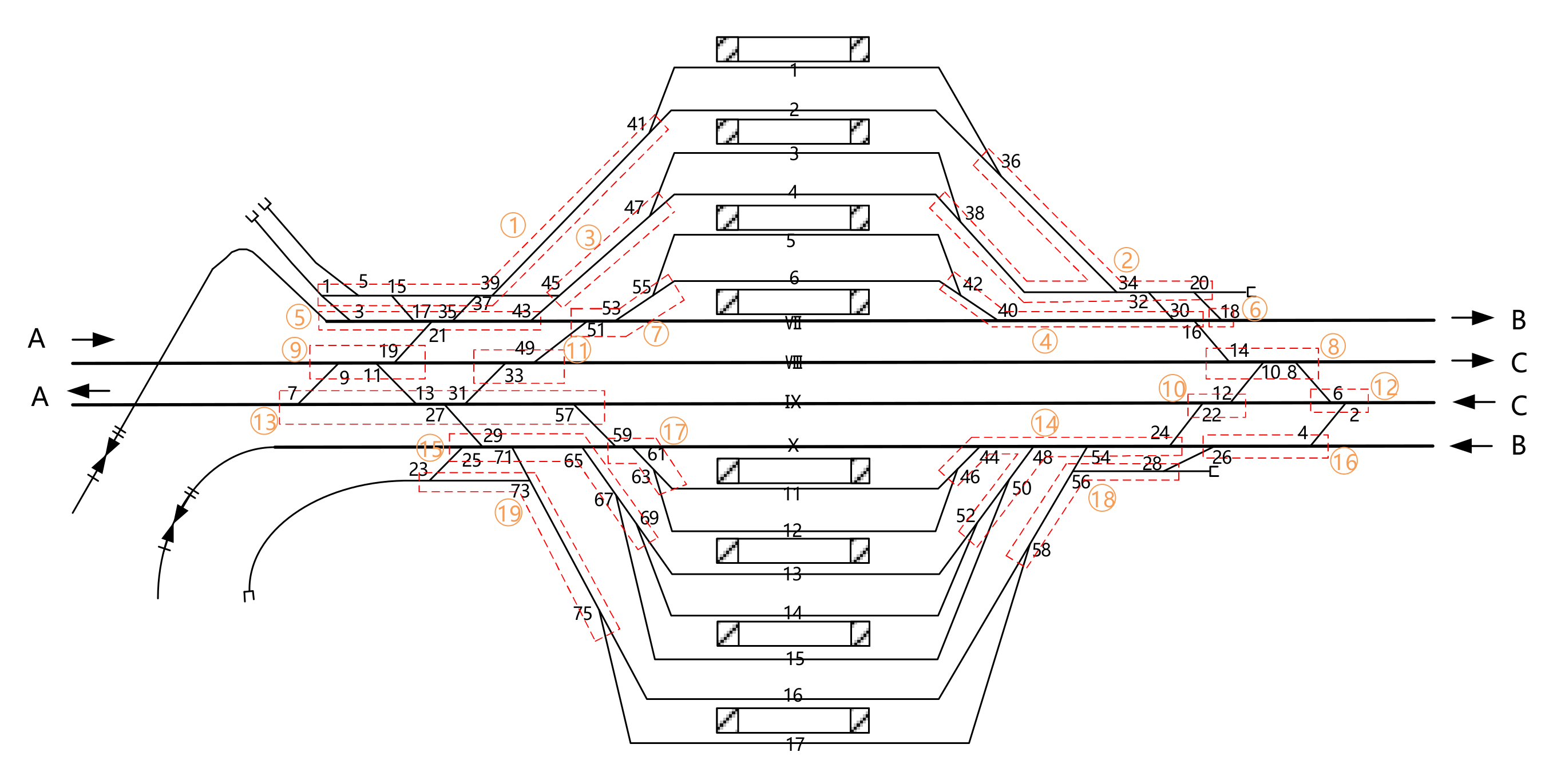
The proposed model is implemented in a high-speed railway station named Jinan Xi, which is located on the Beijing-shanghai high-speed rail line, and the passenger transport volume of it reaches 100,000 people per day during the holiday. The layout of the Jinan Xi station is shown in
Figure 8, with eight platform tracks (1, 2, 3, 4, 5, 6, VII, VIII) in the upstream direction and nine platform tracks (IX, X, 11, 12, 13, 14, 15, 16, 17) in the downstream direction. Moreover, there are 66 downstream and upstream trains, which have to conduct the necessary operations from 17:00 to 20:00. The initial scheduled arrival and departure times of the 66 trains are listed in
Table 5. In the column with combination information of
Table 5, the ordinary train, the combined train and the decomposed train are defined by 0, positive number, and negative number, respectively. For example, in the row with train number G7, the corresponding value of its combination column is −1, which means that G7 is a long marshalling train and will be decomposed in this station; in the row with train number G8, the corresponding value of its combination column is 10, which means that G8 will be grouped with G10 in this station. In the column with direction information of
Table 5, the “A_B” indicates the train whose arrival direction is A and the departure direction is B. “C_C” refers to the train with receiving direction C and departure direction C, the “EMU_B” refers to the train with receiving direction of EMU depot and departure direction B.
The occupation time of various equipment by different types of trains operated in the station is listed in
Table 6. For example, a passing route is occupied by a non-stop train, and the occupation time standard is set as 3 min. The occupation time can be split into two-time durations. The first one is 2 min, from the opening time of the route to the time when the train just reaches the stop line in the receiving-departure track; the second one is 1 min, from the time when the train leaves the departure stop line in the receiving-departure track to the time when it clears the route in the throat area. In addition, parameters
,
,
are all set as 0.5 min. The combined technical operation time of CRH is 16 min, and the disassembly technical operation time is 10 min.
Taking the railroad switch group as the basic unit, several switch groups forms a throat route. A throat route and physically connected platform tracks form a train route for different types of train movements located on. For the detailed information, please refer to
Table 7.
The problem is solved by calling Gurobi software on the Python platform. Firstly, take the objective function (1) and constraints (3~12) as the model I, the objective function (2) and constraints (3~12) as the model II, and then solve the two models, respectively. Using the solving method presented in
Section 4.4, the nondominated solution [
,
] of the model I is [11013, 11475], and the nondominated solution [
,
] of the model II is [420.477, 1669.771]. As shown in
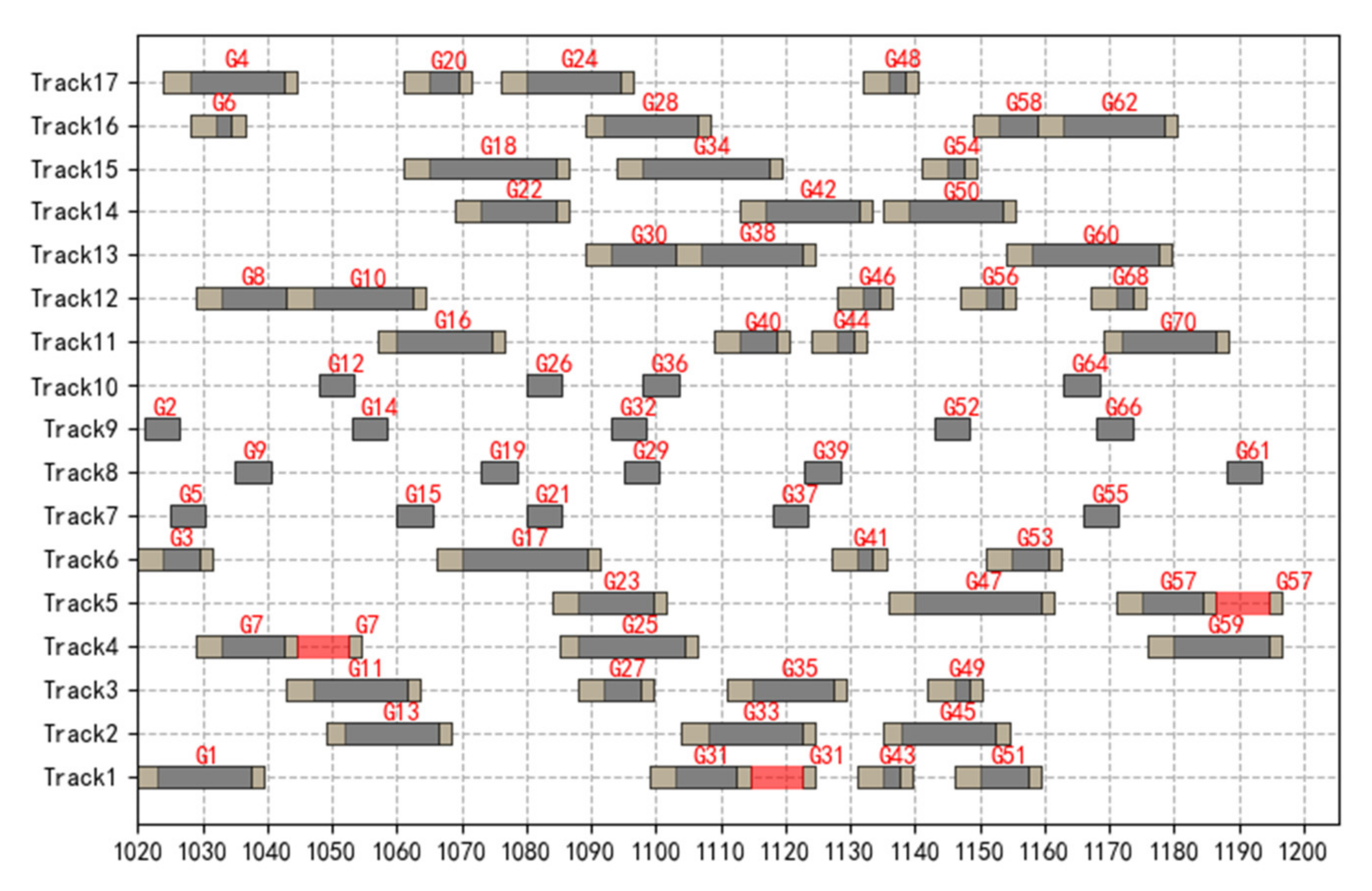
Figure 9 and
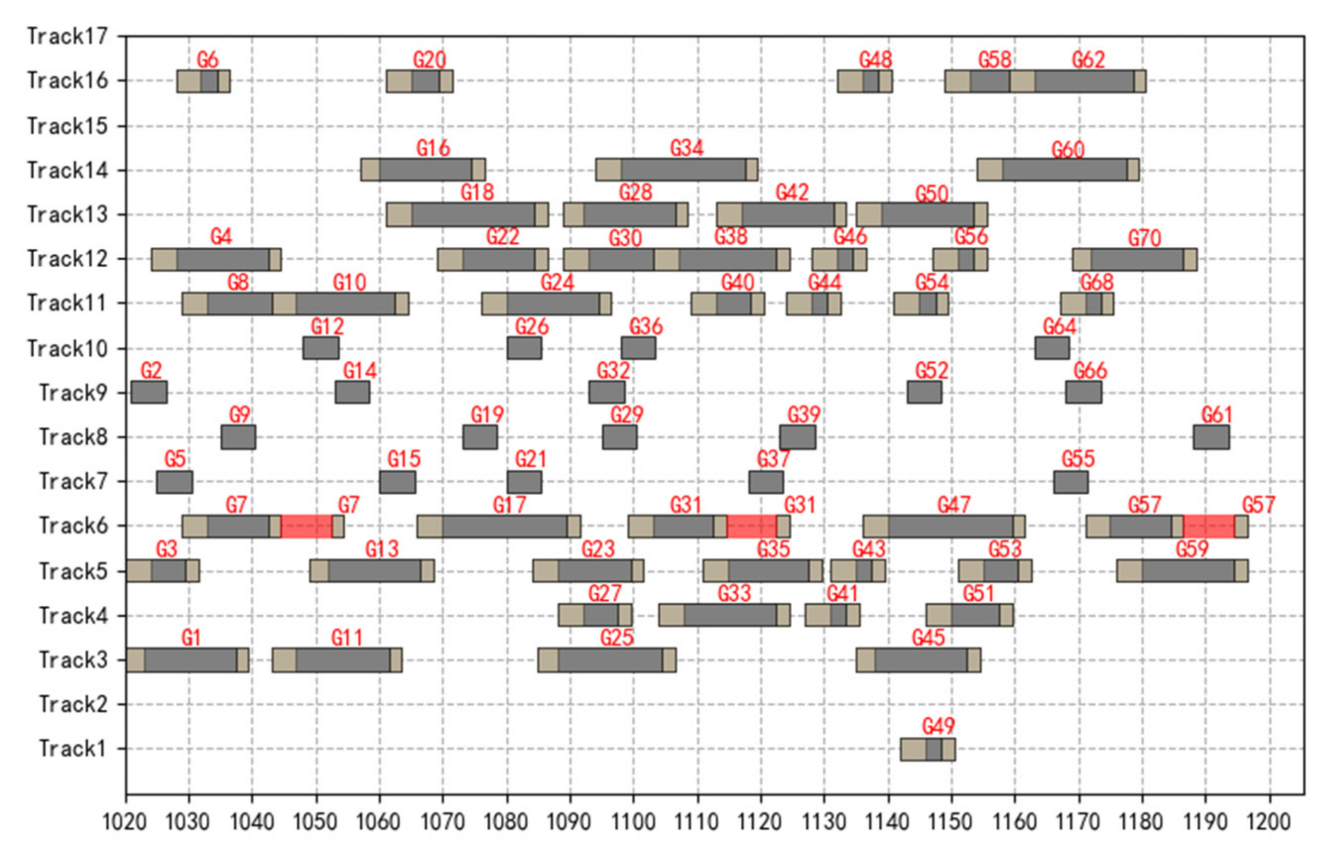
Figure 10, the gray-white blocks in these figures correspond to the time that trains occupy the receiving route or the departure route in the throat section due to receiving and departure movements, the gray and black blocks correspond to the dwell time of the train on the platform tracks. After the large train is disassembled into two short marshalling trains, the waiting time of the later departing short marshalling train on the receiving-departure track is represented by a red stripe block. The time occupied by the non-stop trains passing through the receiving-departure track is equal to a certain time.
Figure 9 shows the scheme of train occupying receiving-departure track based on model I, which aims at minimizing the route cost, and
Figure 10 shows the scheme of train occupying receiving-departure track based on the model II, which aims at achieving the most balanced equipment occupation.
Through comparison, it can be concluded the route with the lowest cost has priority to be selected for trains, and trains are concentrated on certain platform tracks for receiving and departure movements, resulting in that the track 2, 15 and 17 are not occupied by trains, which also proves that the capacity of station platform tracks is sufficient. The utilization rate of each track in
Figure 10 is relatively balanced, which avoids the centralized receiving and departure movements of trains on some arrival and departure lines, and reduces the probability of train delay. The scheme of
Figure 10 has strong stability, but the comprehensive cost of receiving and departure trains is relatively high.
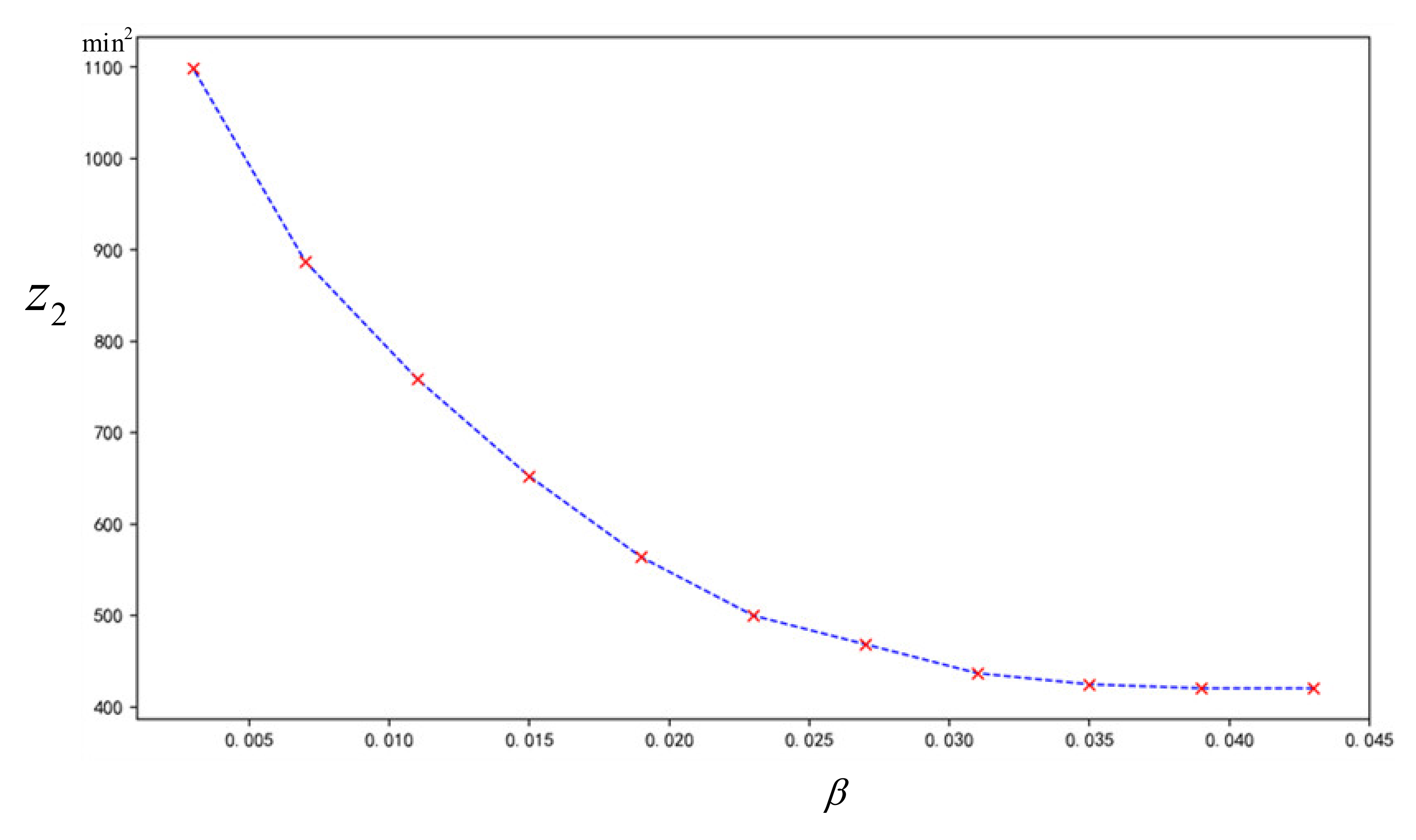
In this paper, the influence of the change of the value of
z1 on the value
z2 is observed by adjusting the value of
β. The specific experimental method is as follows: Take 11 values evenly from the value range of
according to the principle of equal division, and input them into the constraint (17) in turn, solve the newly constructed model III and observe the objective function value of
with
. The results are shown in
Figure 11. It can be found from the analysis chart that with the increase value of
, that is, the route cost of the scheme increases, the value of objective function
gradually decreases, and the occupation of platform tracks is more balanced. When the
increases to 4.19%, the scheme with the maximum equilibrium has been obtained. At this time, it is impossible to continue to improve the equilibrium of the scheme by increasing the route cost.
Take the solution obtained when
is 1.9% into the objective function (2), and the calculated function value
is 563.889. Take it into the objective function (1), and the obtained function value
is 11222. When the value of
is 0, the obtained solution is input into the objective function (2) and objective function (1), respectively, and the calculated function values of
and
are 1669.771 and 11013, respectively. Comparing the two train routing schemes with
values of 1.9% and 0%, it is found that although the former increases the value of
by 1.9%, it can reduce the value of
by 66.2%. As a result, the solution obtained when
is 1.9% is taken as a comprehensive application scheme. In addition, a feasible scheme is generated according to certain rules obeyed by dispatchers, and taken it as an actual operation scheme, then bring it into objective function (1) and (2), the values of
and
are 11440 and 666.948, respectively. The comparison results of the comprehensive application scheme and actual operation scheme are shown in
Table 8. It can be seen that the comprehensive operation scheme reduces the route cost by 1.9% and improves the occupation balance of platform tracks by 15.4%.
In order to further investigate the impact of the increase in the number of combined and decomposed trains on station operation, some tests are made in the current station. On the premise that the total number of arriving trains is the same, the number of combined or decomposed trains is set to 2, 4, 6, 8, 10, 12, etc. The tests are carried out when is 1.9%. The results state that the balance of arrival departure track utilization decreases significantly with the increase in the number of combined and decomposed trains. This is due to the rigid constraint requirements on the connection relationship between the combined and the decomposed trains on the track occupation.
Therefore, for some stations with tight capacity utilization, the number of combined or decomposed trains should be reduced as much as possible. The appropriate stations to be selected for train combination and decomposition will be a further research problem.
6. Conclusions
Train operation at stations is a practical problem for the railway operation department. This paper studies the train route assignment problem, and considers the combination and decomposition process of trains at stations. Based on the analysis of the actual operation process of various types of trains in China high-speed railway stations and the occupation times of route in the throat area and in platform tracks, a multi-objective mathematical optimization model is constructed, aiming at minimizing the cost of route occupied by trains and minimizing the differences in track utilization. To tackle the intractable problem of determining the weight value when solving the multi-objective mathematical programming model, this paper presents a solution framework based on the “constraint method”, and a software Gurobi is used to solve the model. The results indicate that the differences in track utilization rate can be improved to 66.2% when the cost of route occupation time increases by 1.9%. The above shows that when the track time occupation cost in the new scheme increases slightly, the occupation balance of each track can be greatly improved. It also indicates that if the carrying capacity of station platform tracks is sufficient, a balanced utilization scheme for each track shall be generated; if the carrying capacity of the station is insufficient, the plan with the minimizing occupation time cost of platform tracks shall be formulated. In addition, it is found that the balance of the utilization of the platform tracks decreases significantly with the increase in the number of combined and decomposed trains.
Due to the combination and decomposition movement of trains on the platforms in a station, more station capacity will be taken up, which may cause more train delays, especially at busy stations. As a result, we will integrate the train routing problem and station selection problem for train combination or decomposition from the perspective of a whole line, so that the capacity utilization of stations is more reasonable, and the combination and decomposition scheme of trains can meet the passenger demand as much as possible. Moreover, train delays may cause a chain reaction across the whole railway network. Therefore, future studies can take into account the train-routing problem integrated with train timetable rescheduling in a railway network.


