
Influence of Friction on the Behavior and Performance of Prefabricated Timber–Bearing Glass Composite Systems


Abstract
:1. Introduction
2. Timber–glass Hybrid Elements: A Brief Literature Overview
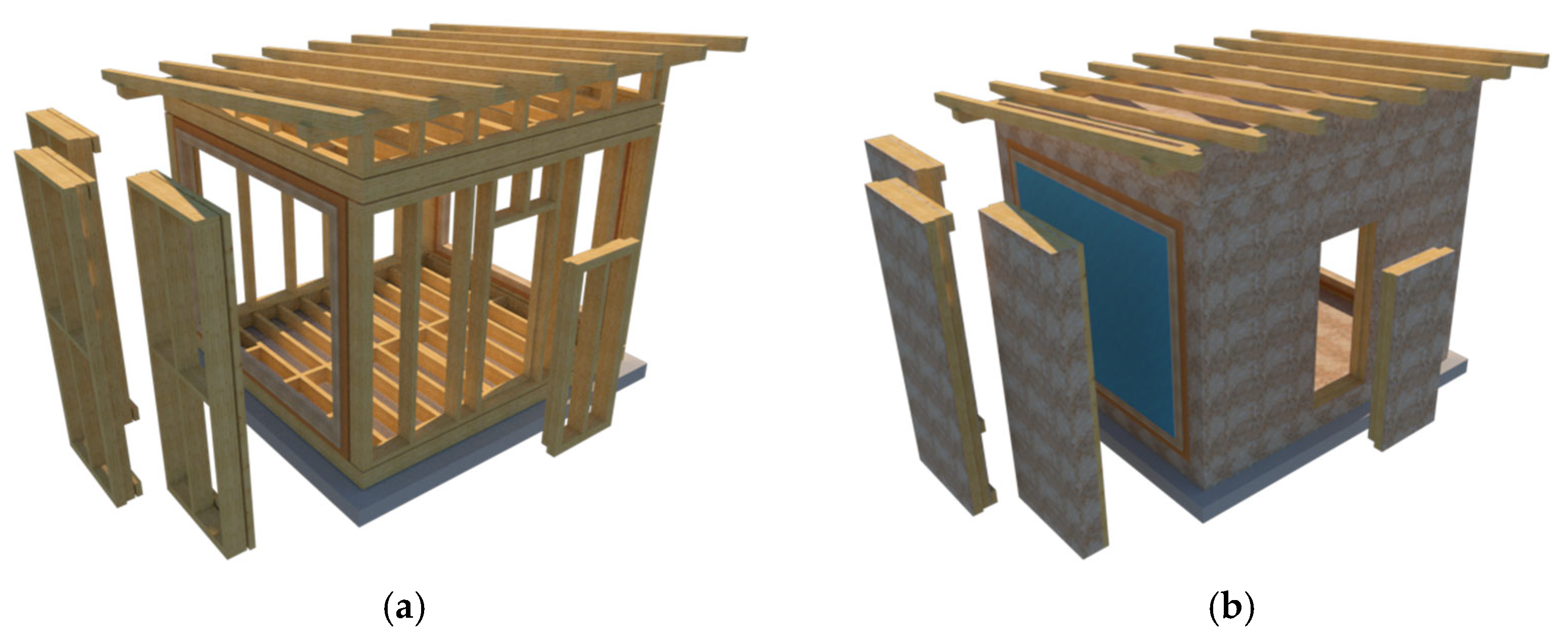
3. Prototype of a Multifunctional Wood–Bearing Glass Composite System
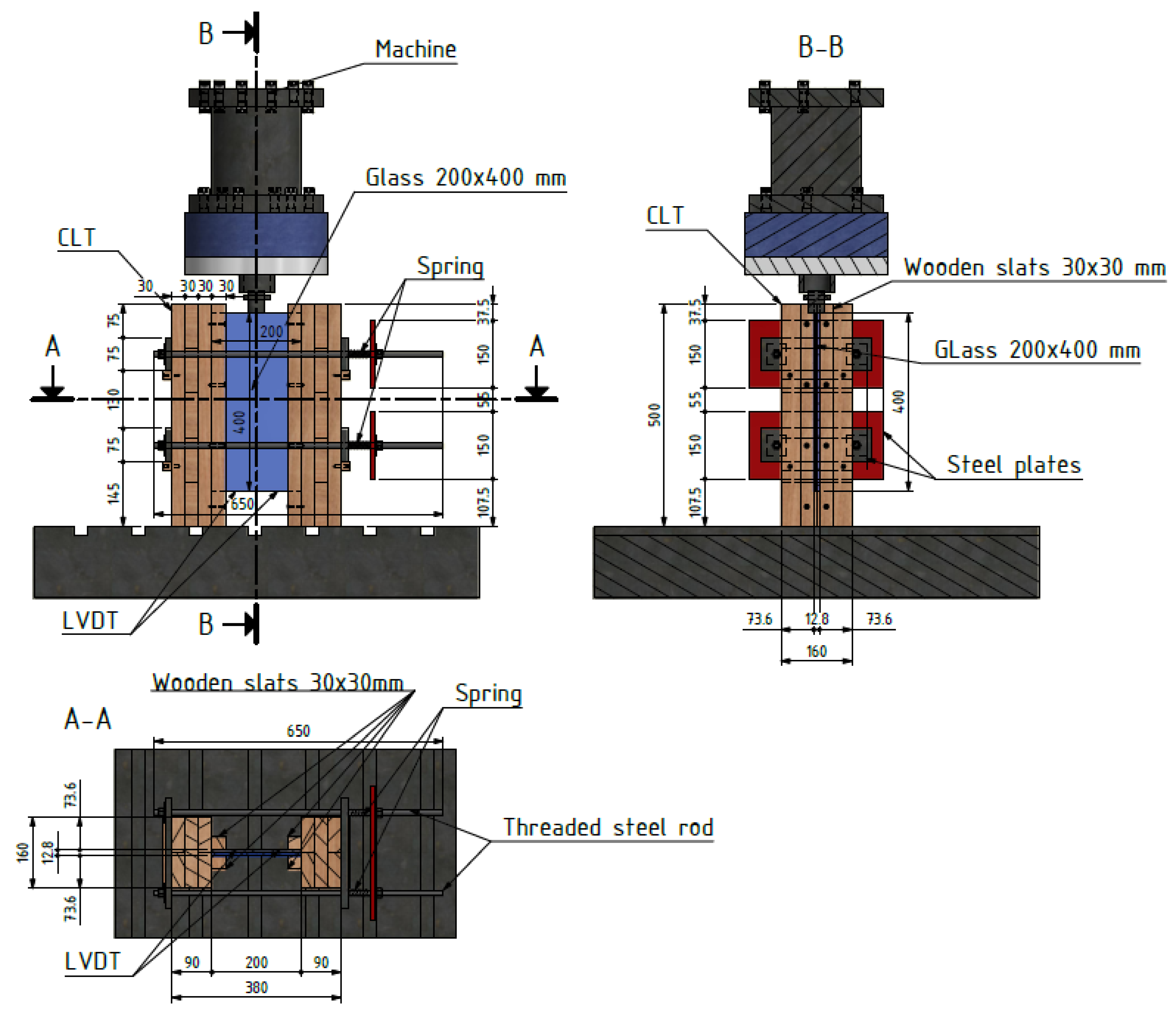
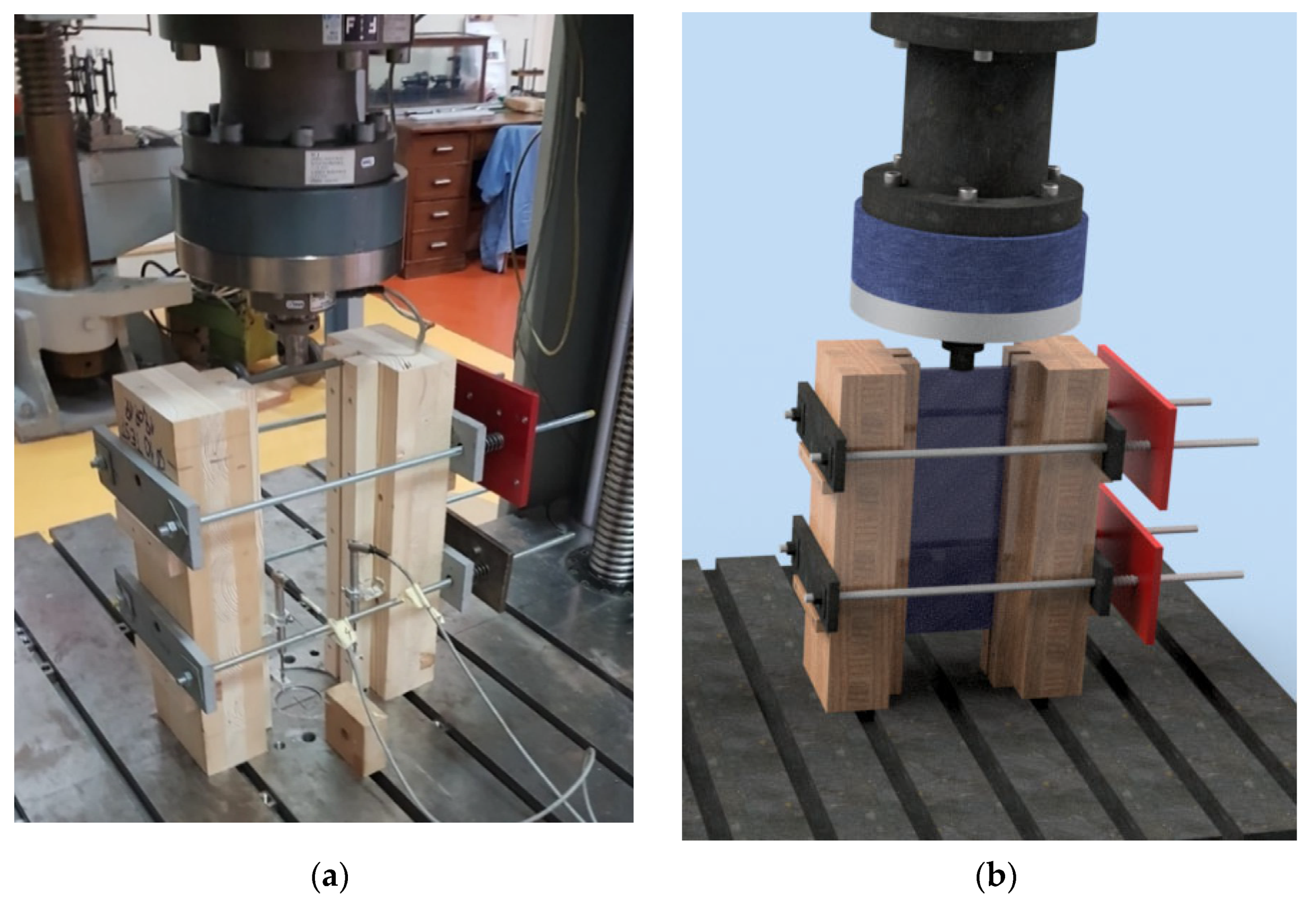
4. Materials and Methods
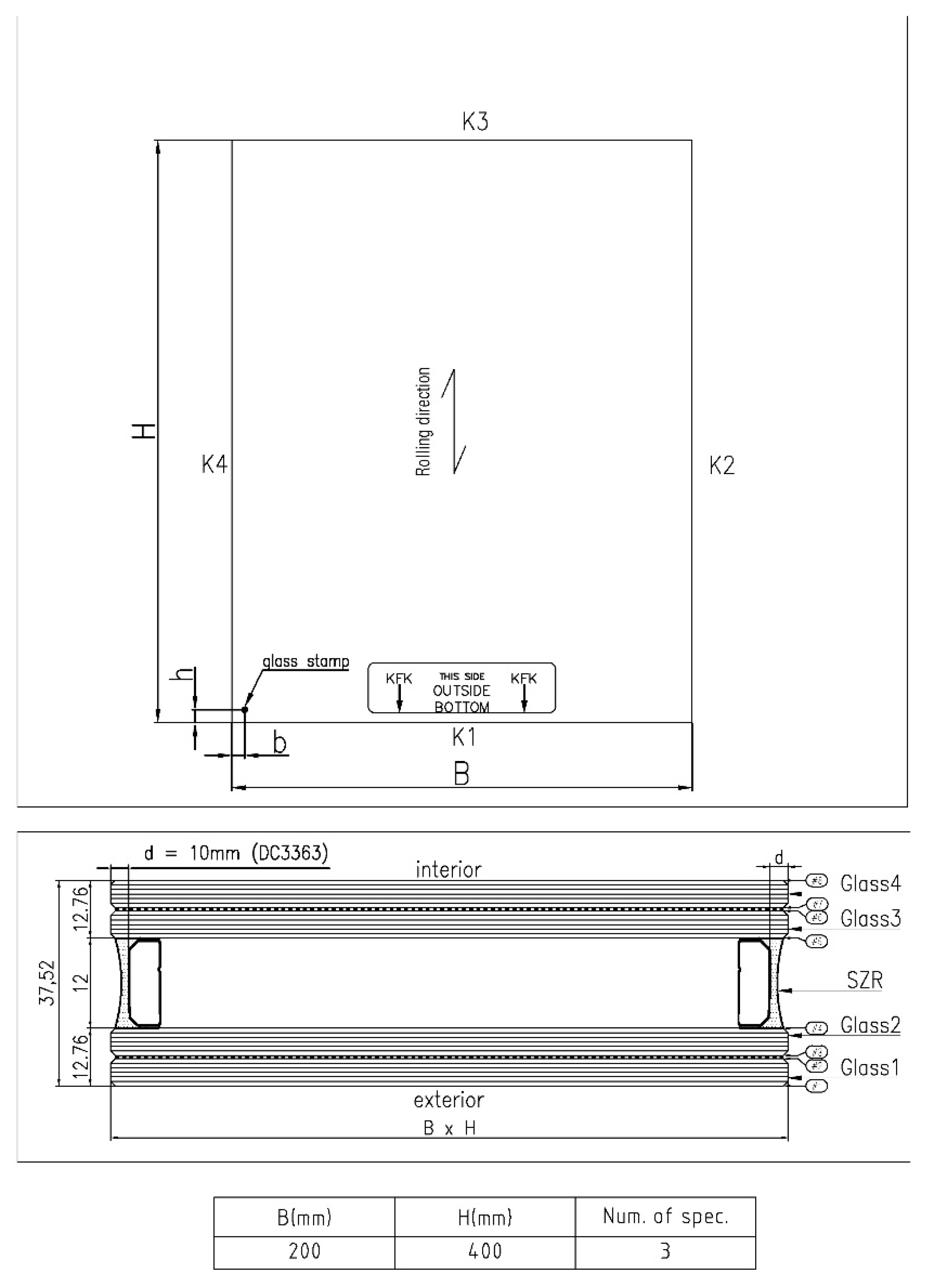
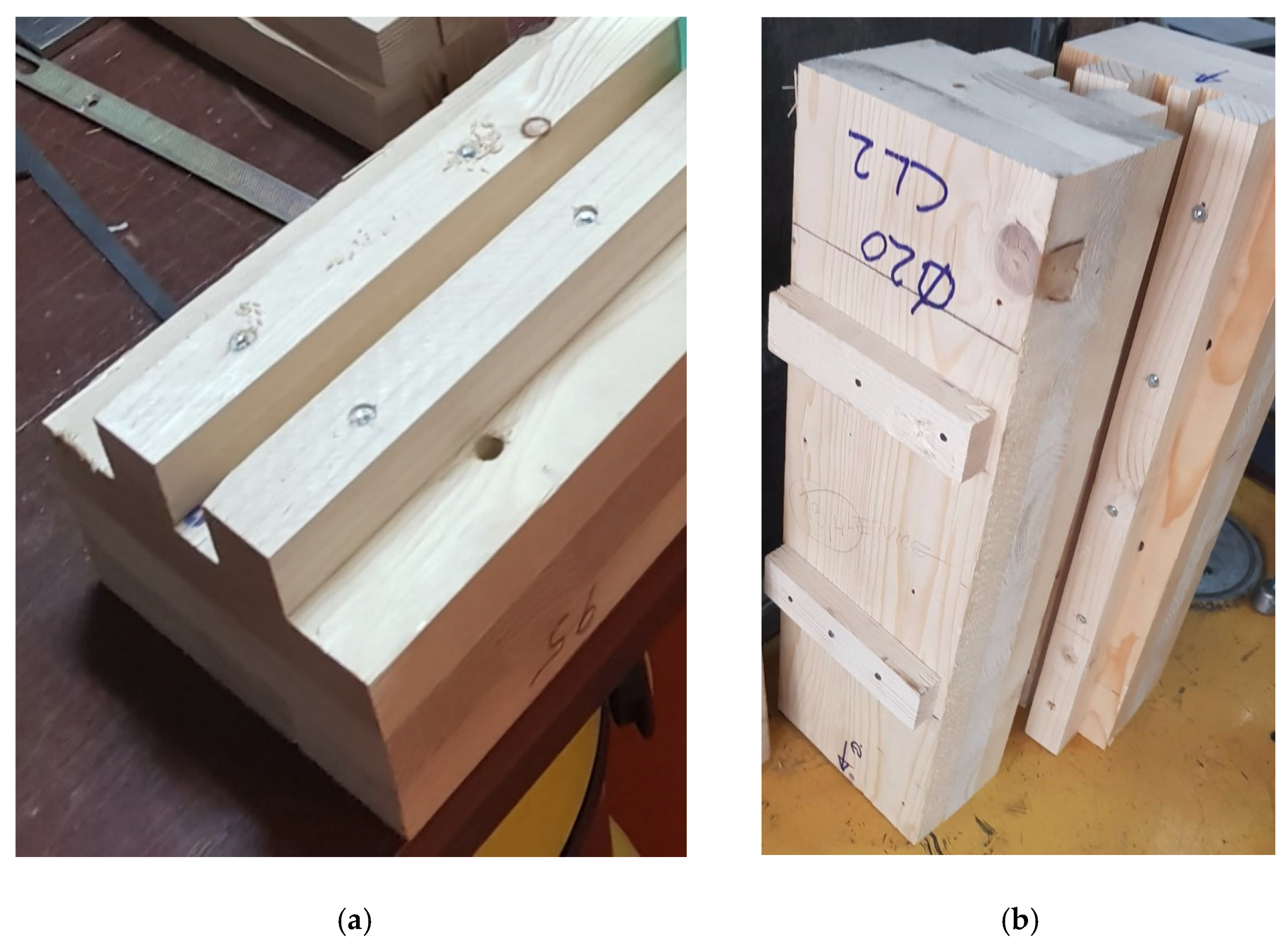
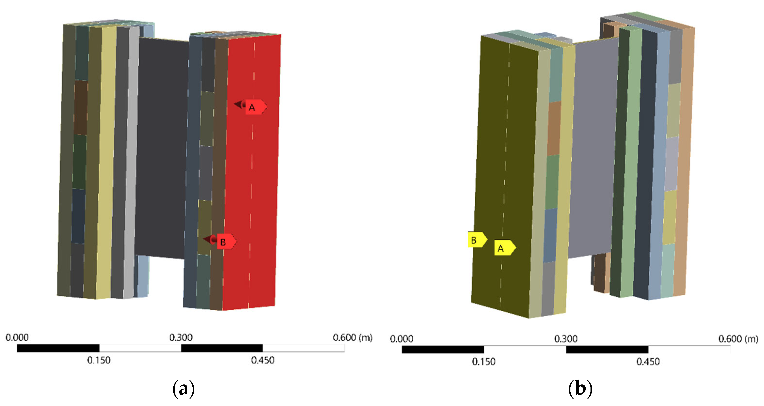
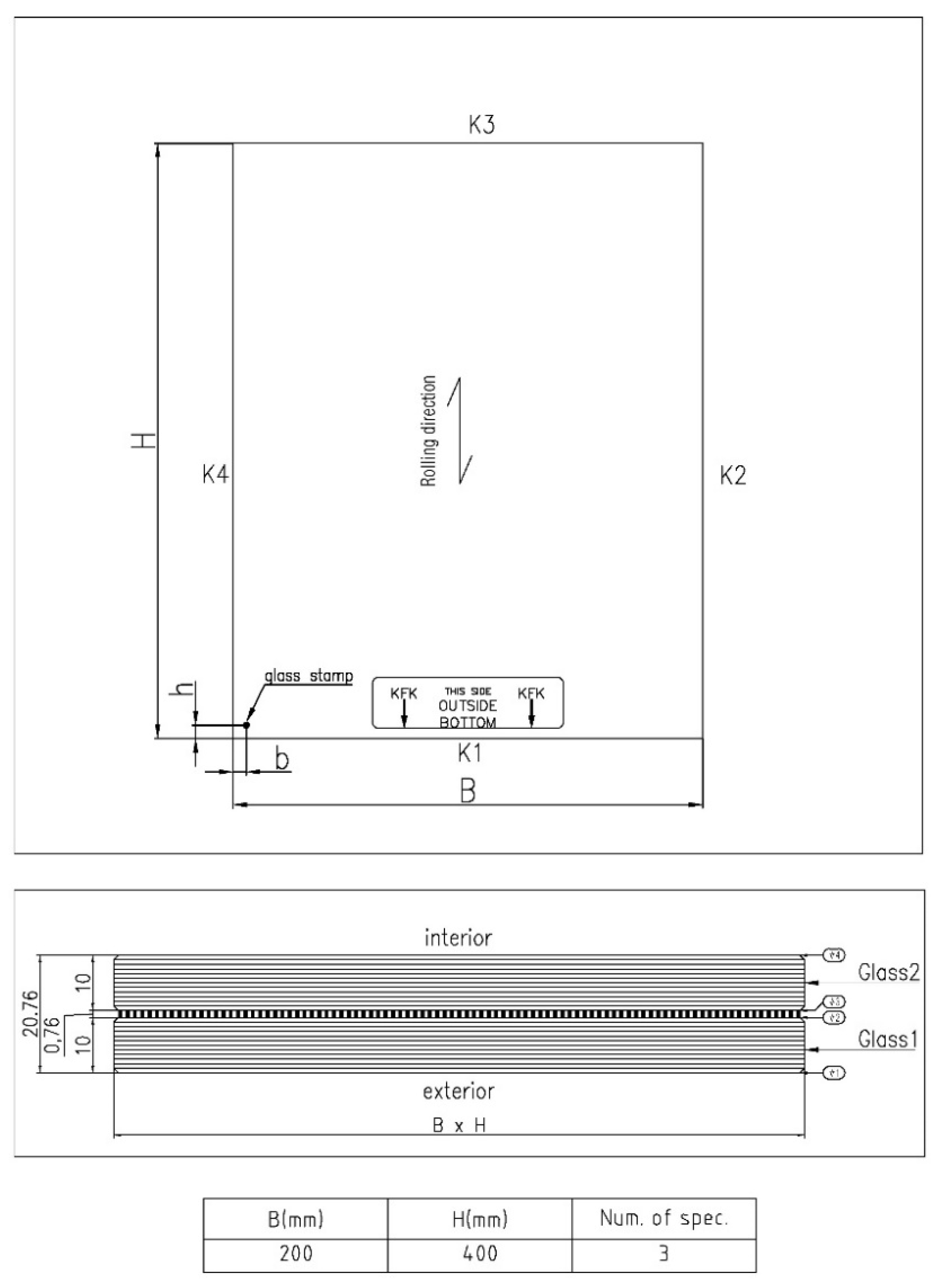
Description and Preparation of Specimens
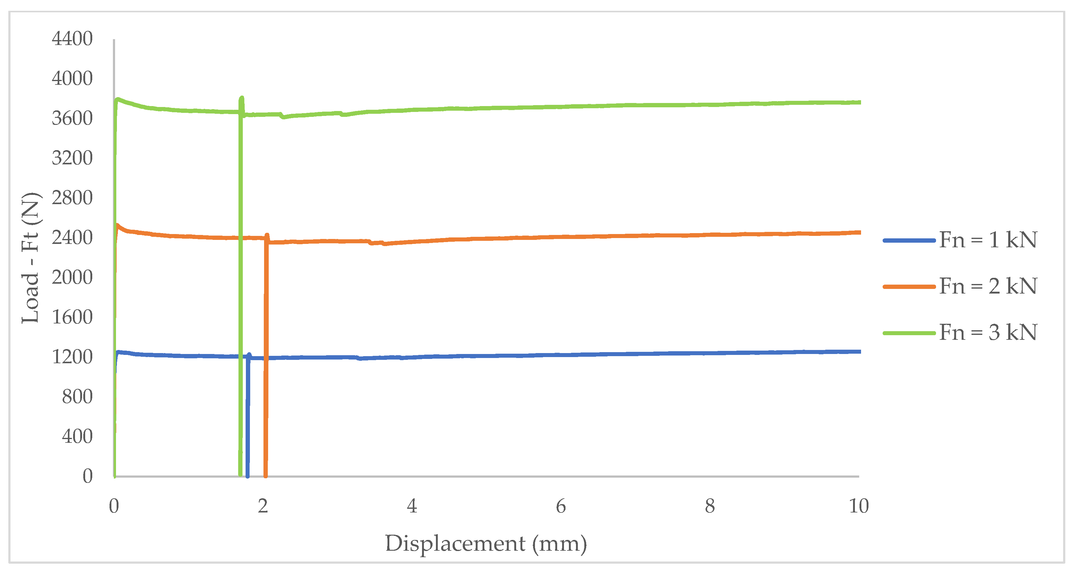
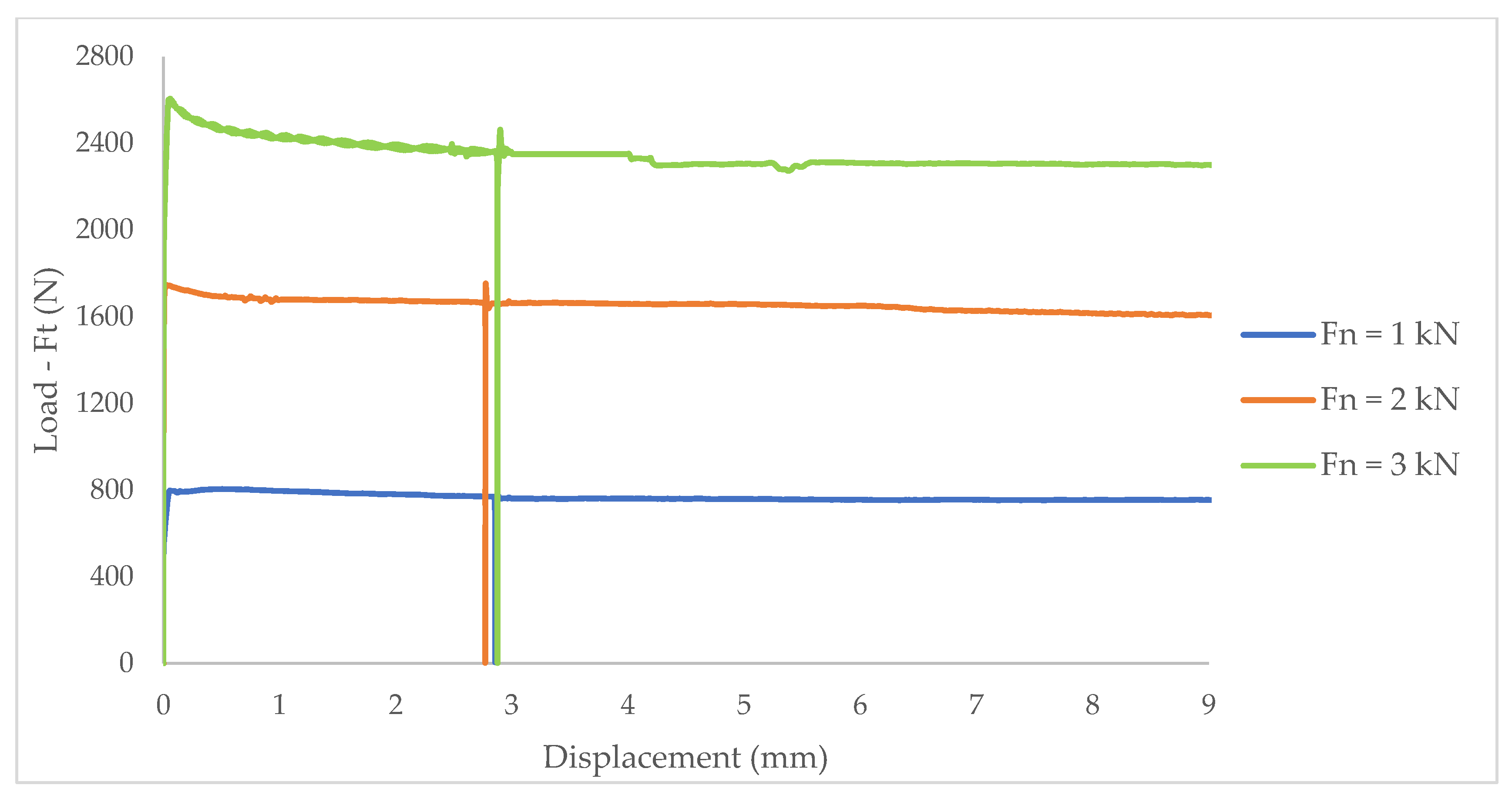
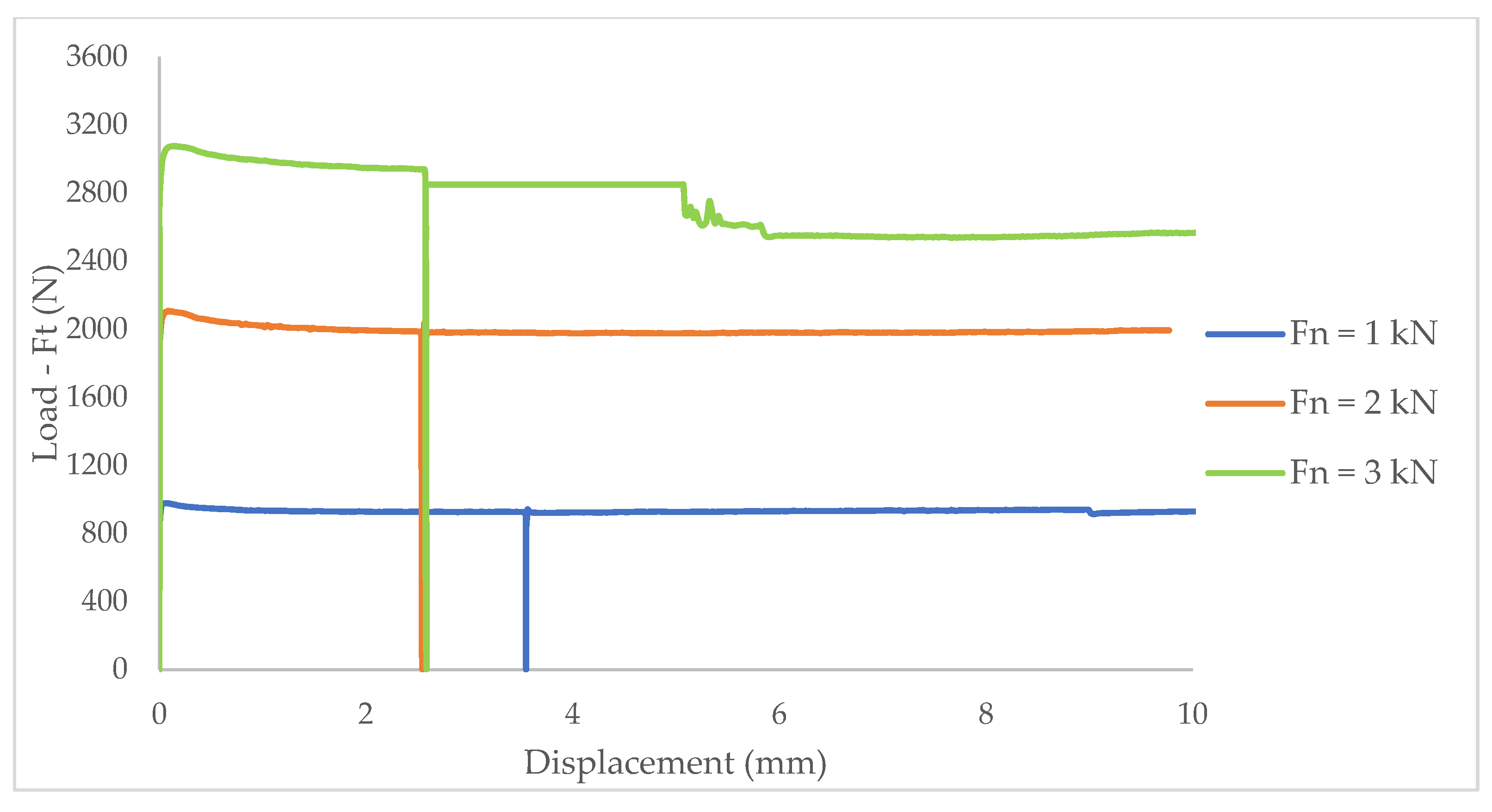
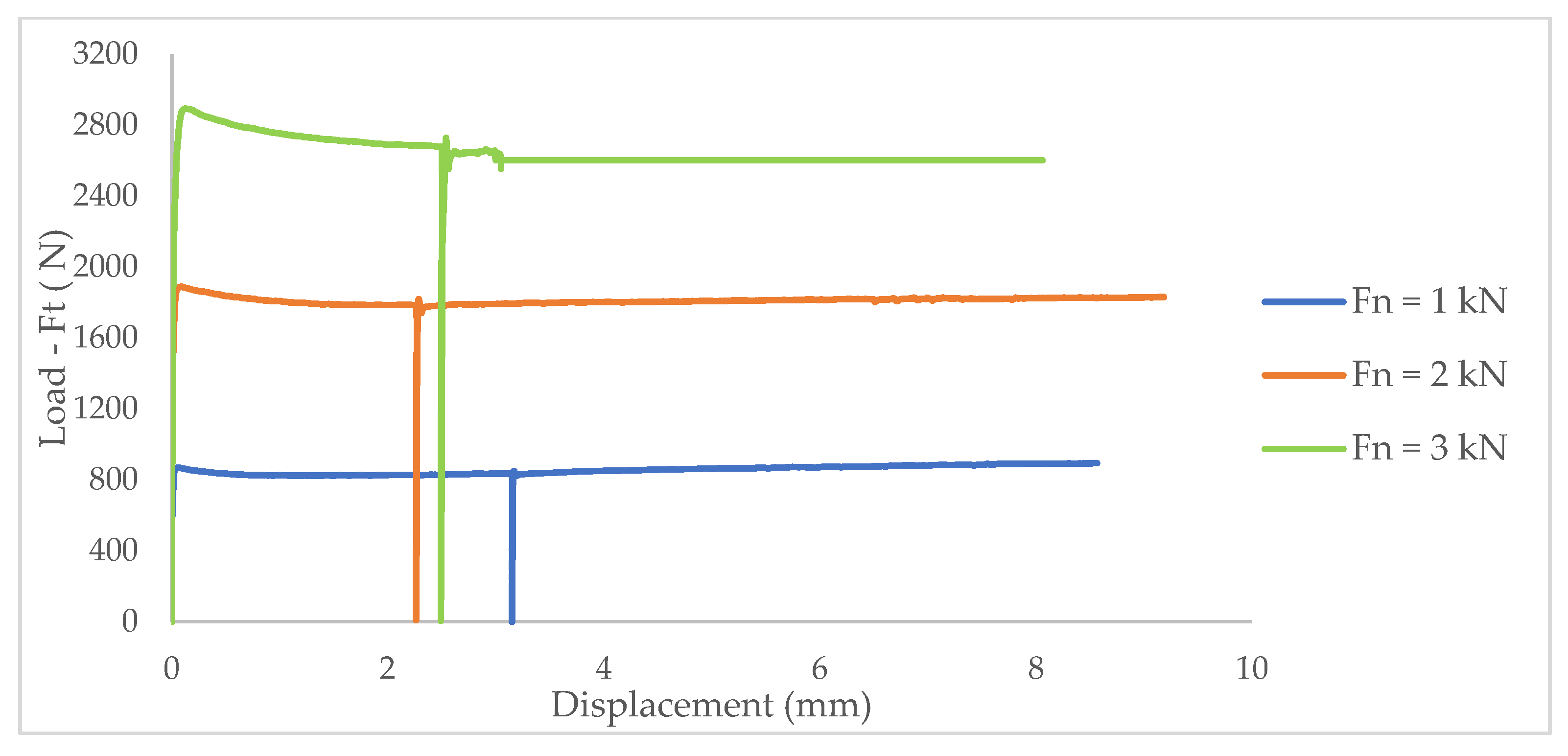
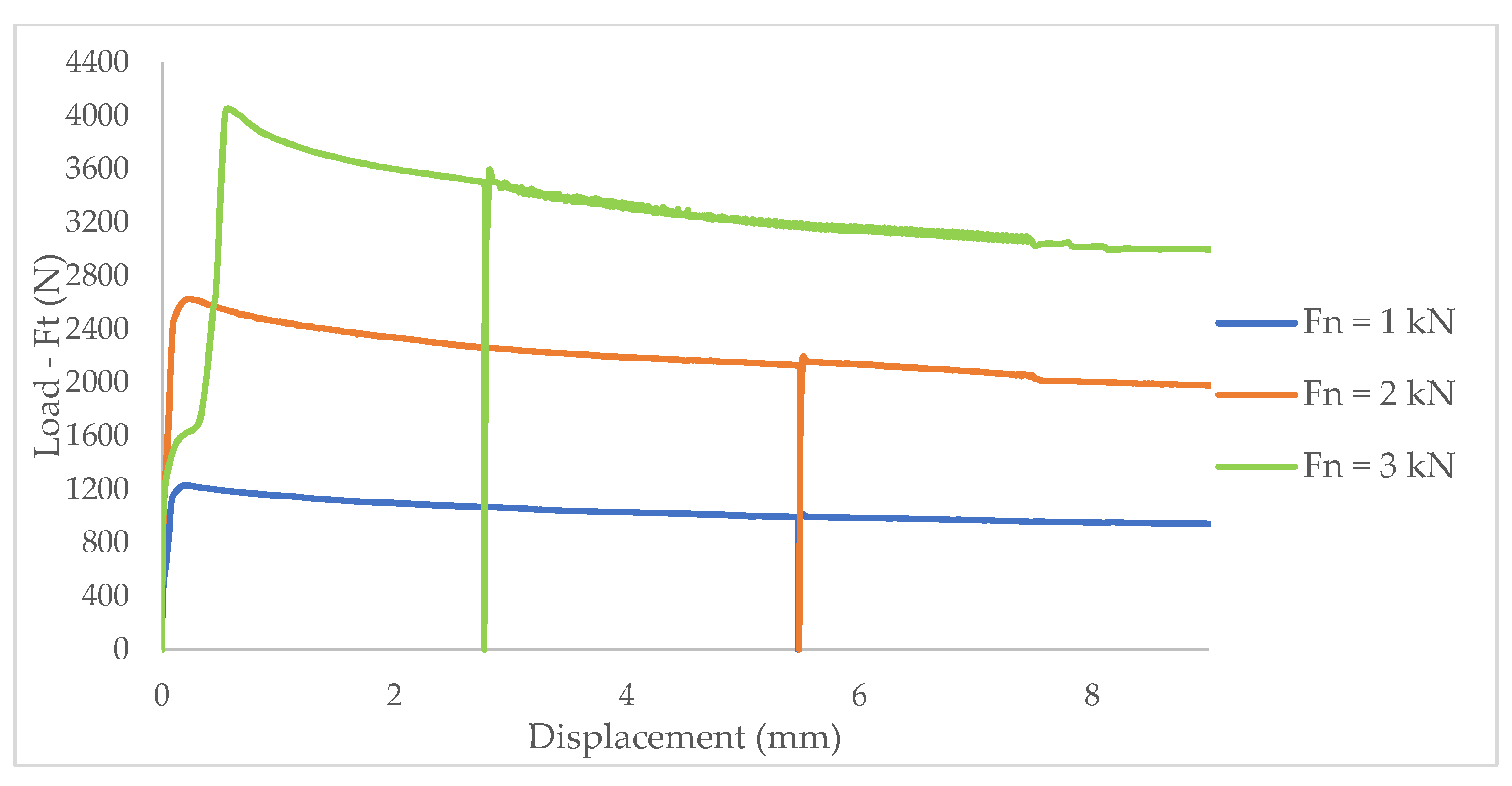
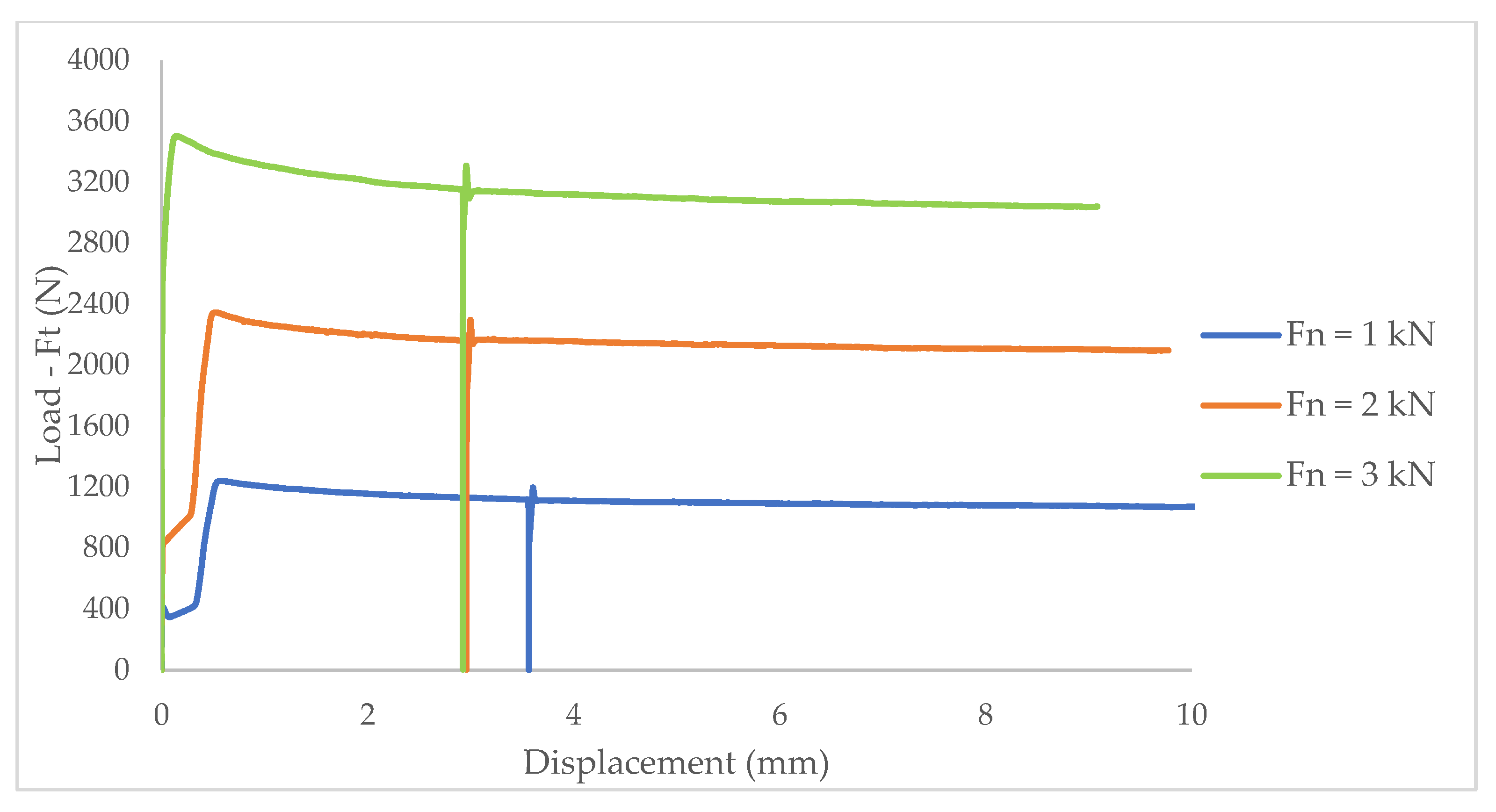
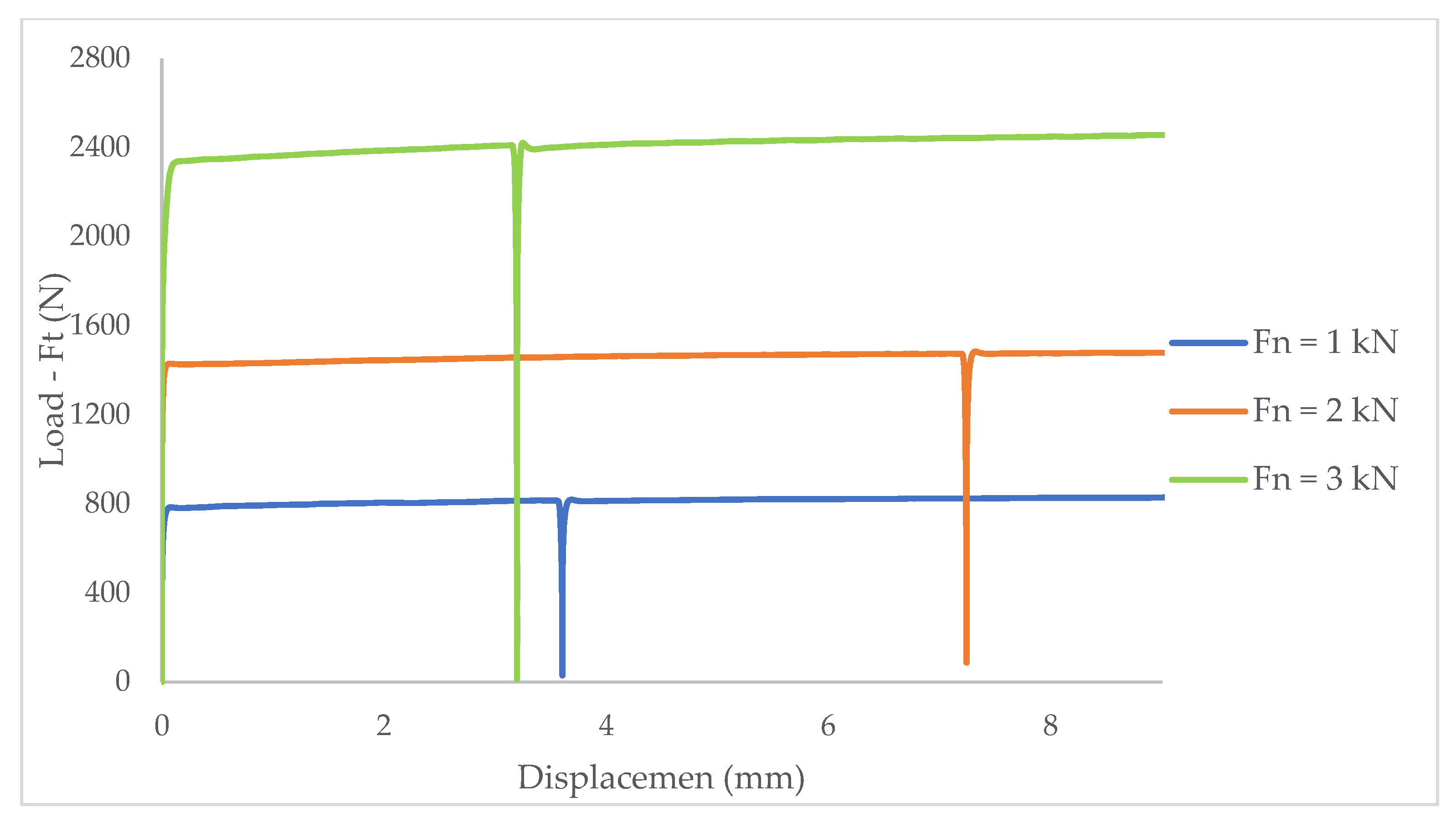
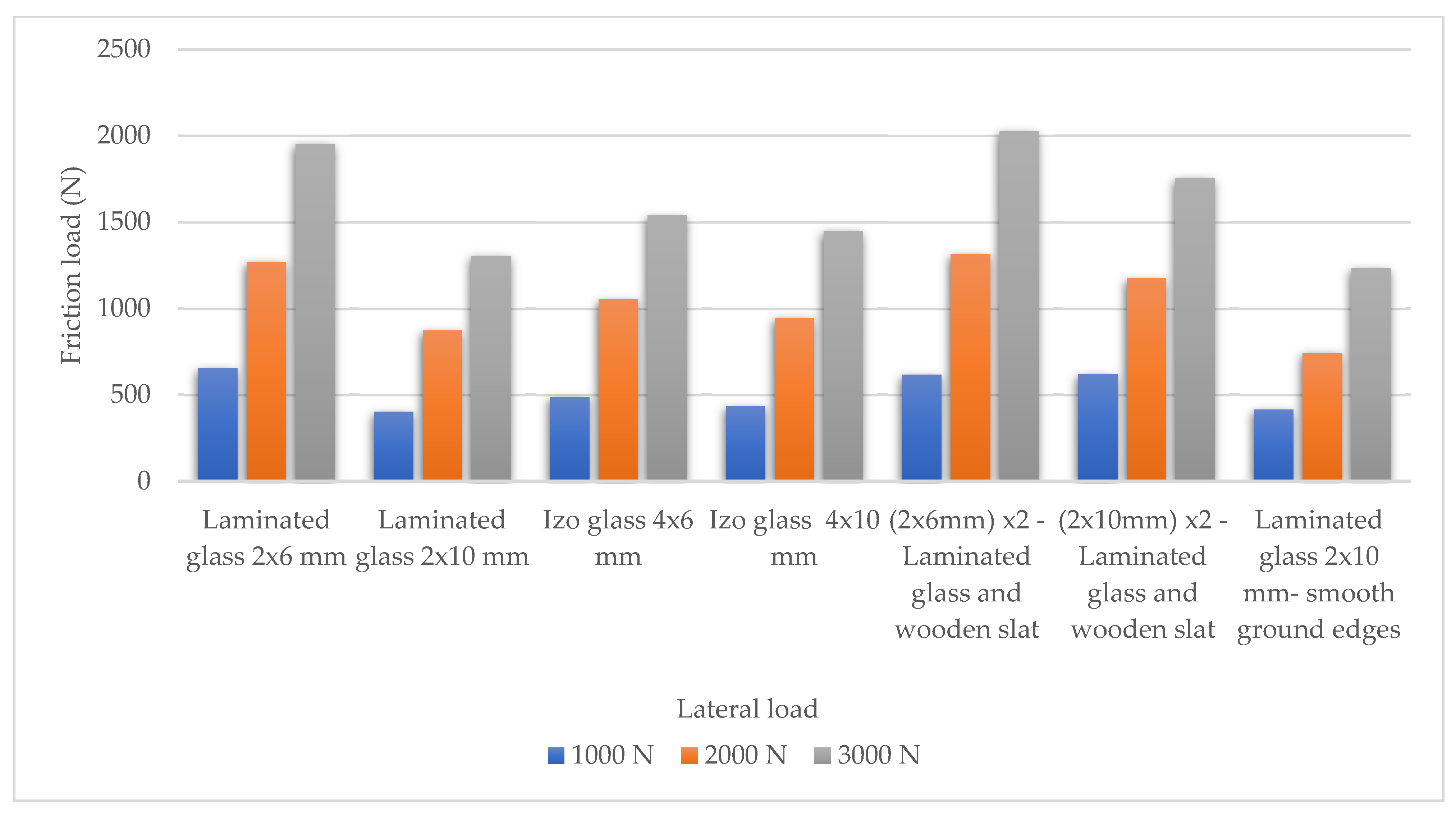
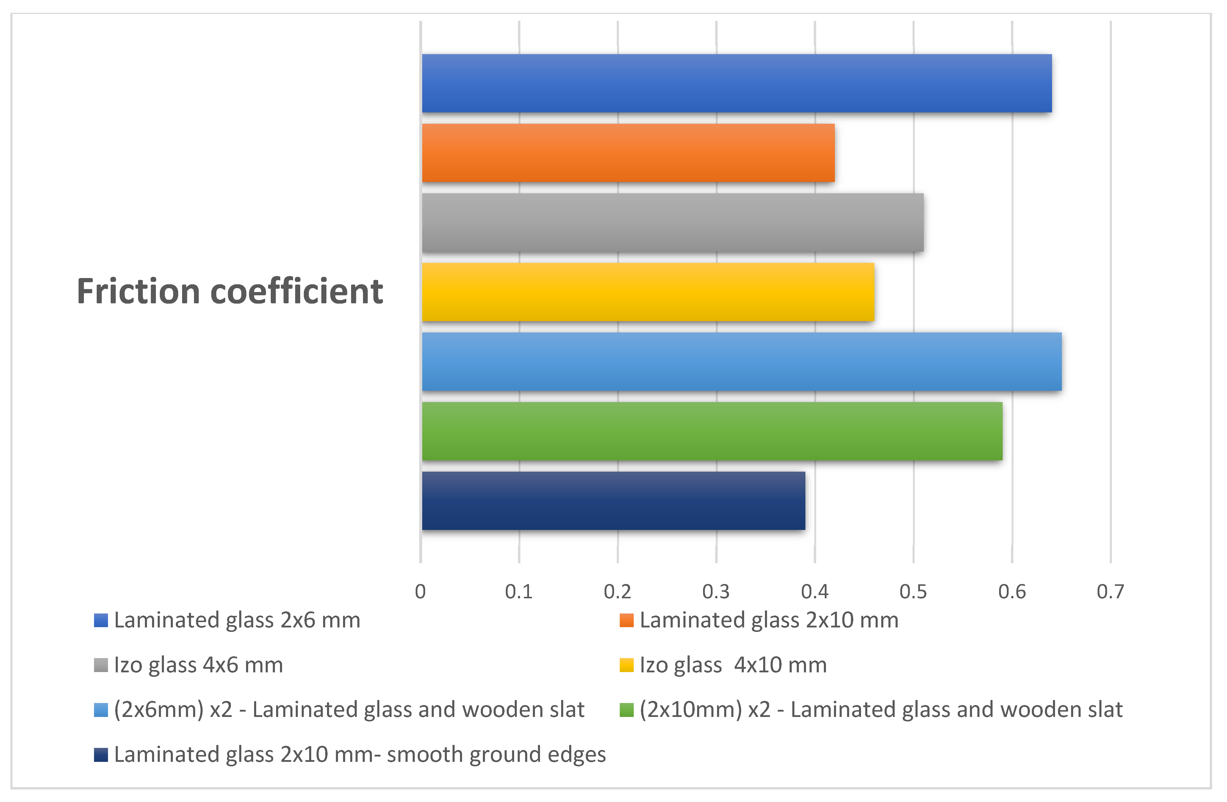
5. Experimental Work
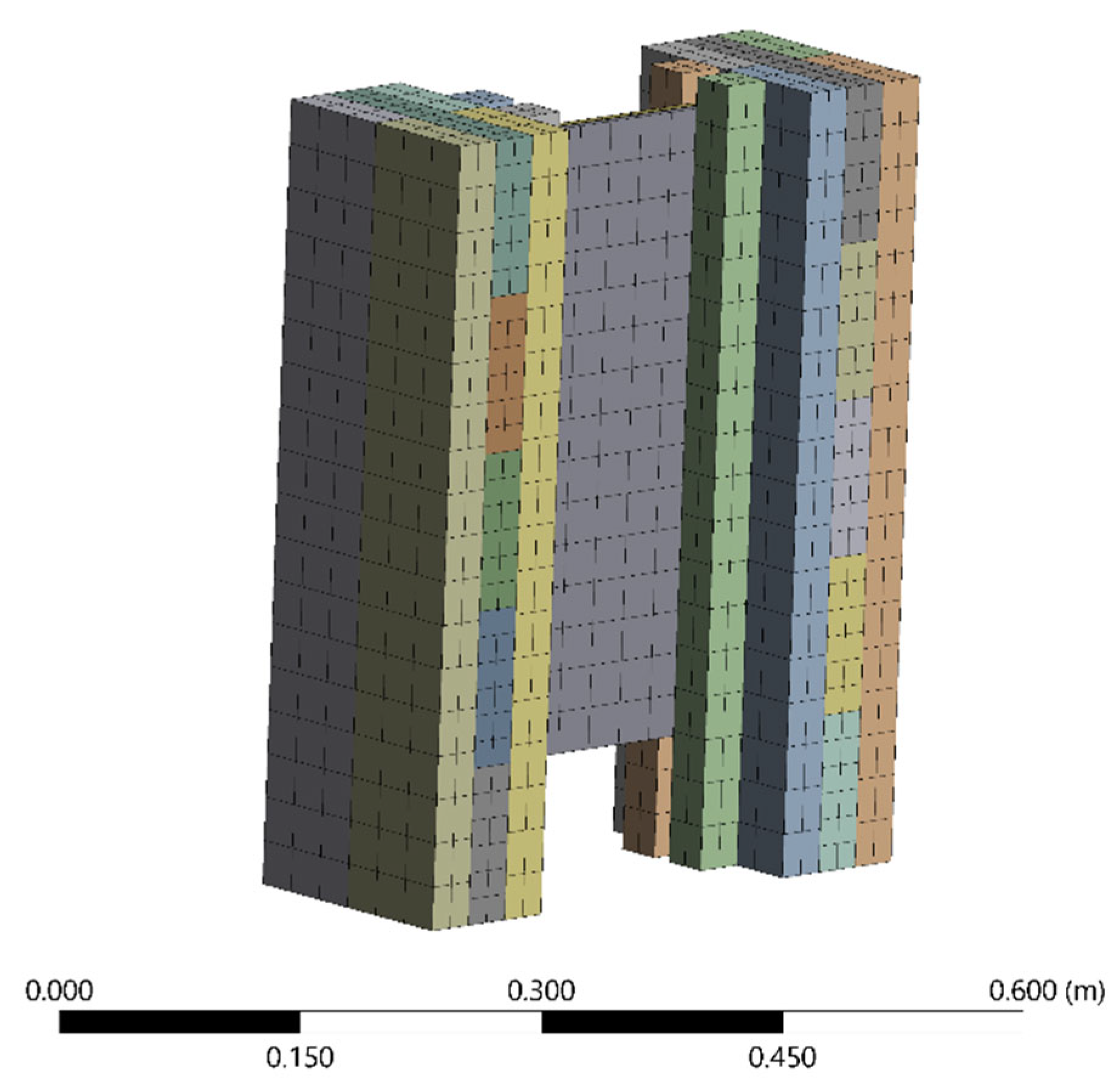
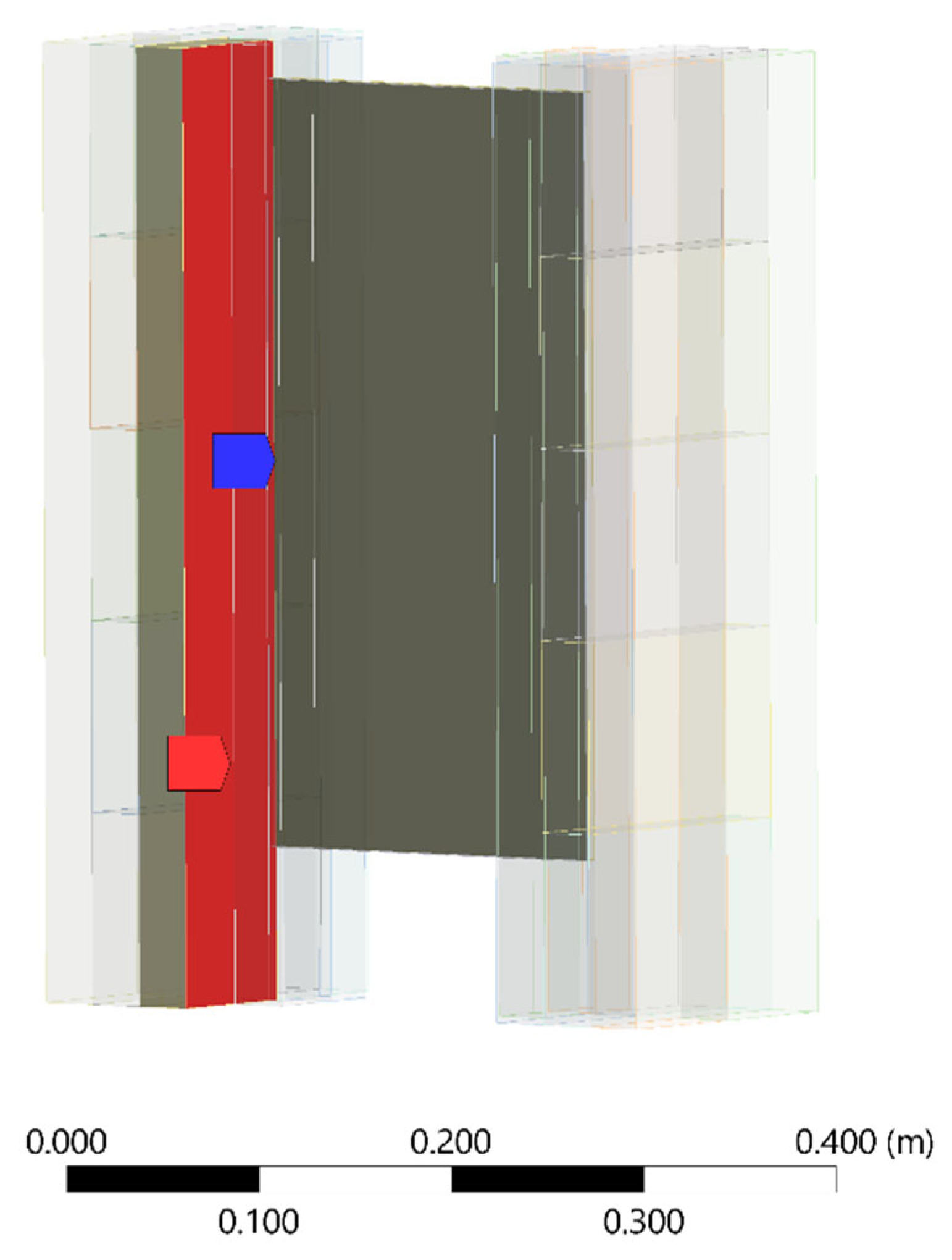
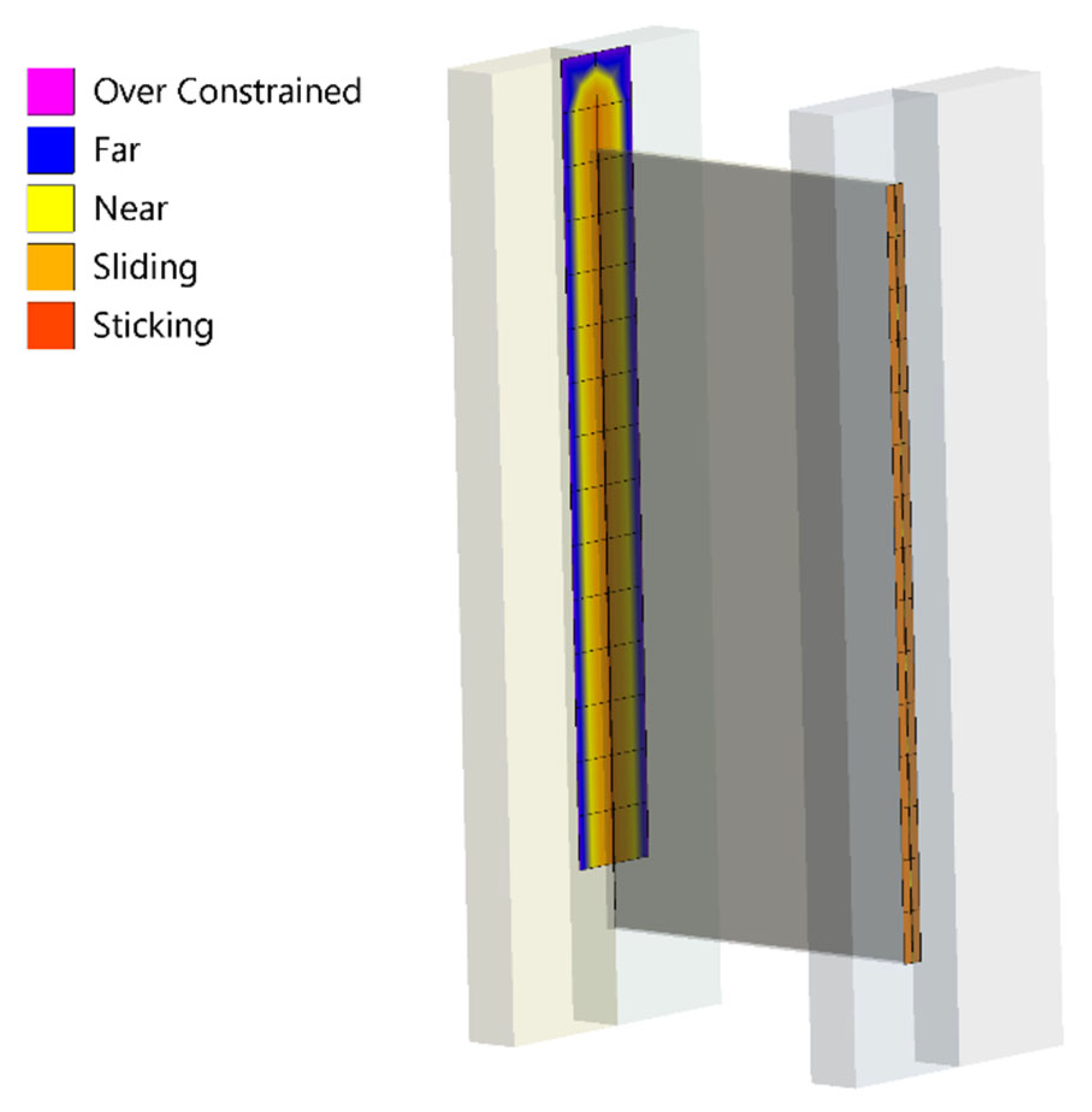
6. FEM Research
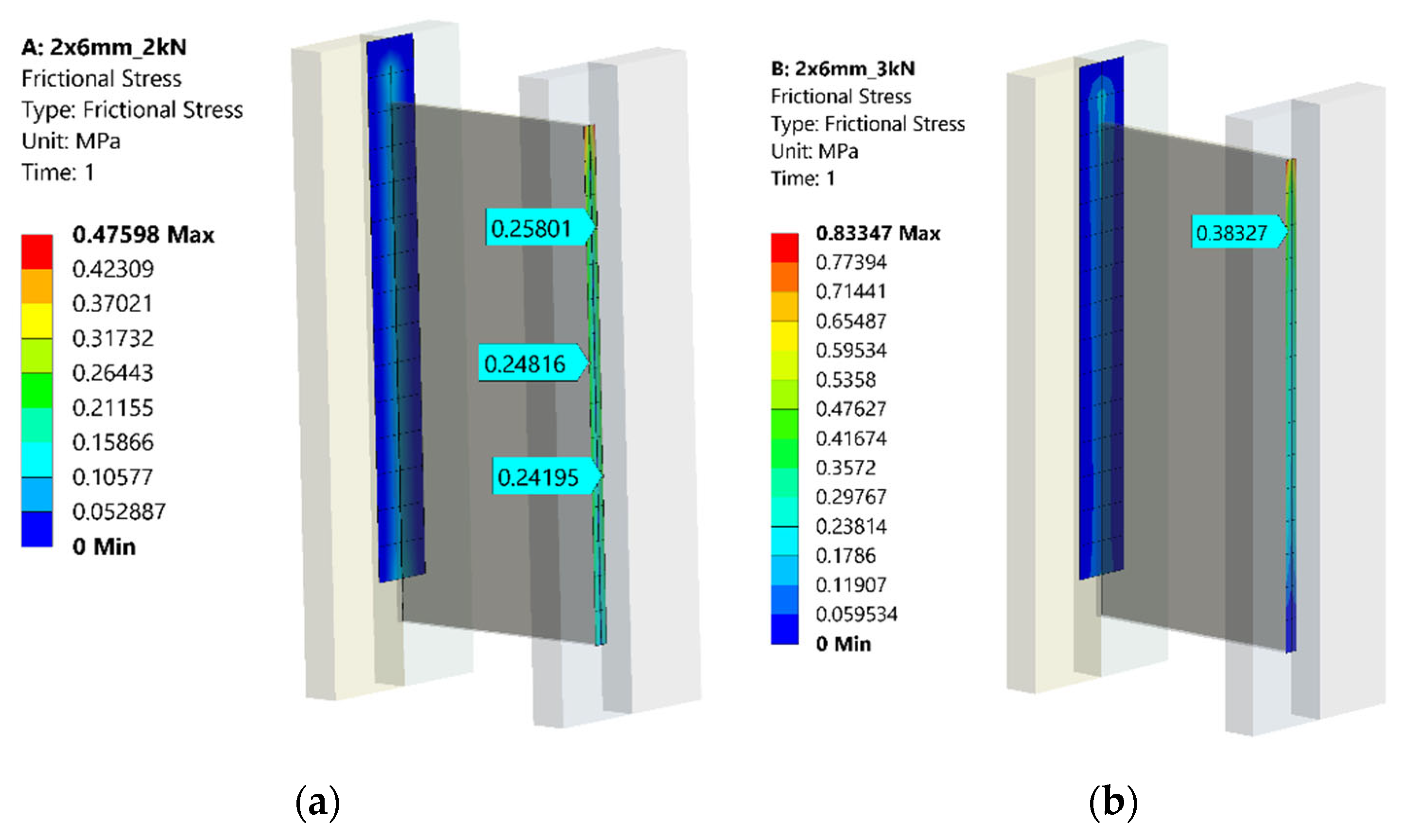
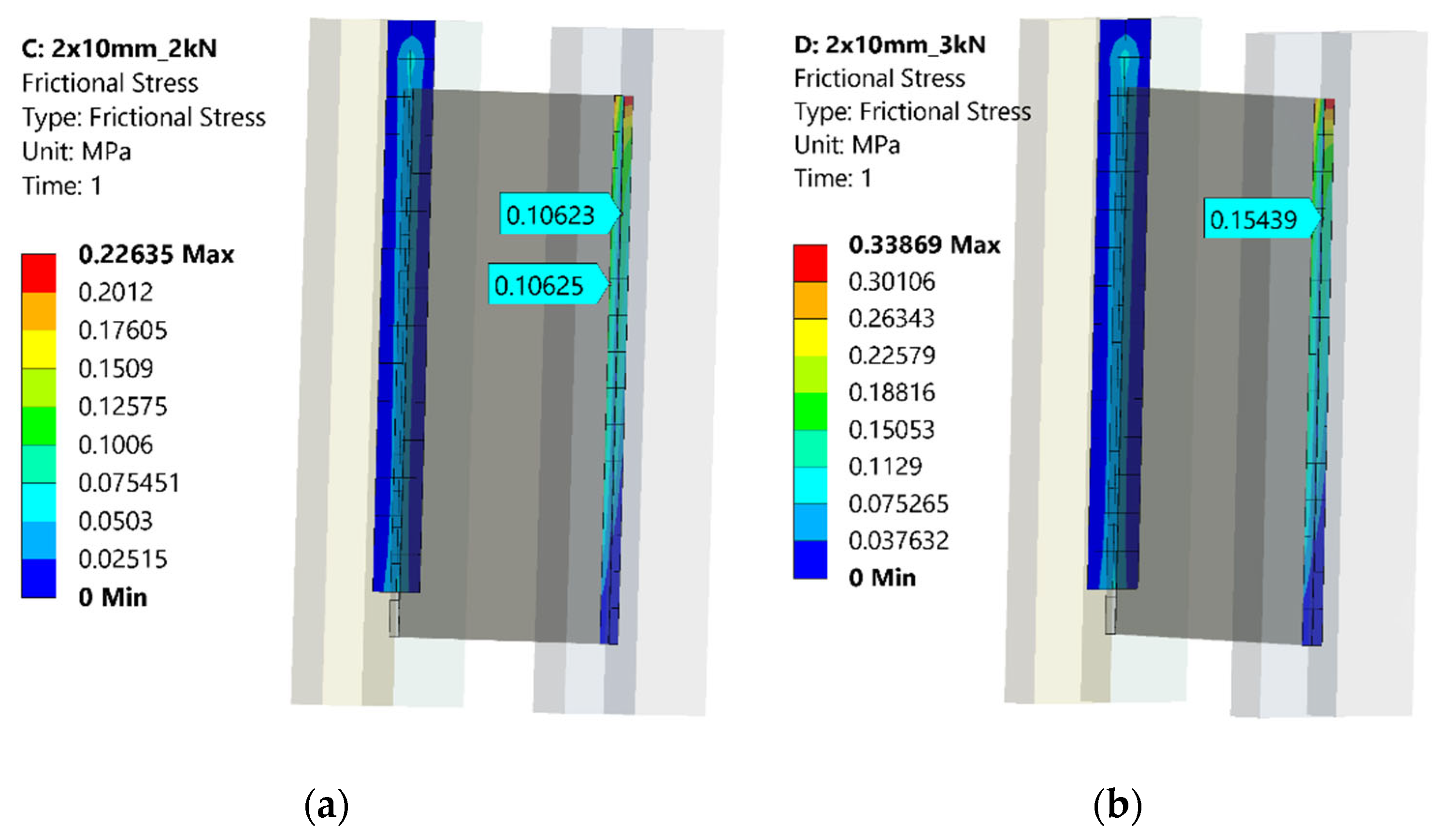
FEM Results
7. Discussion
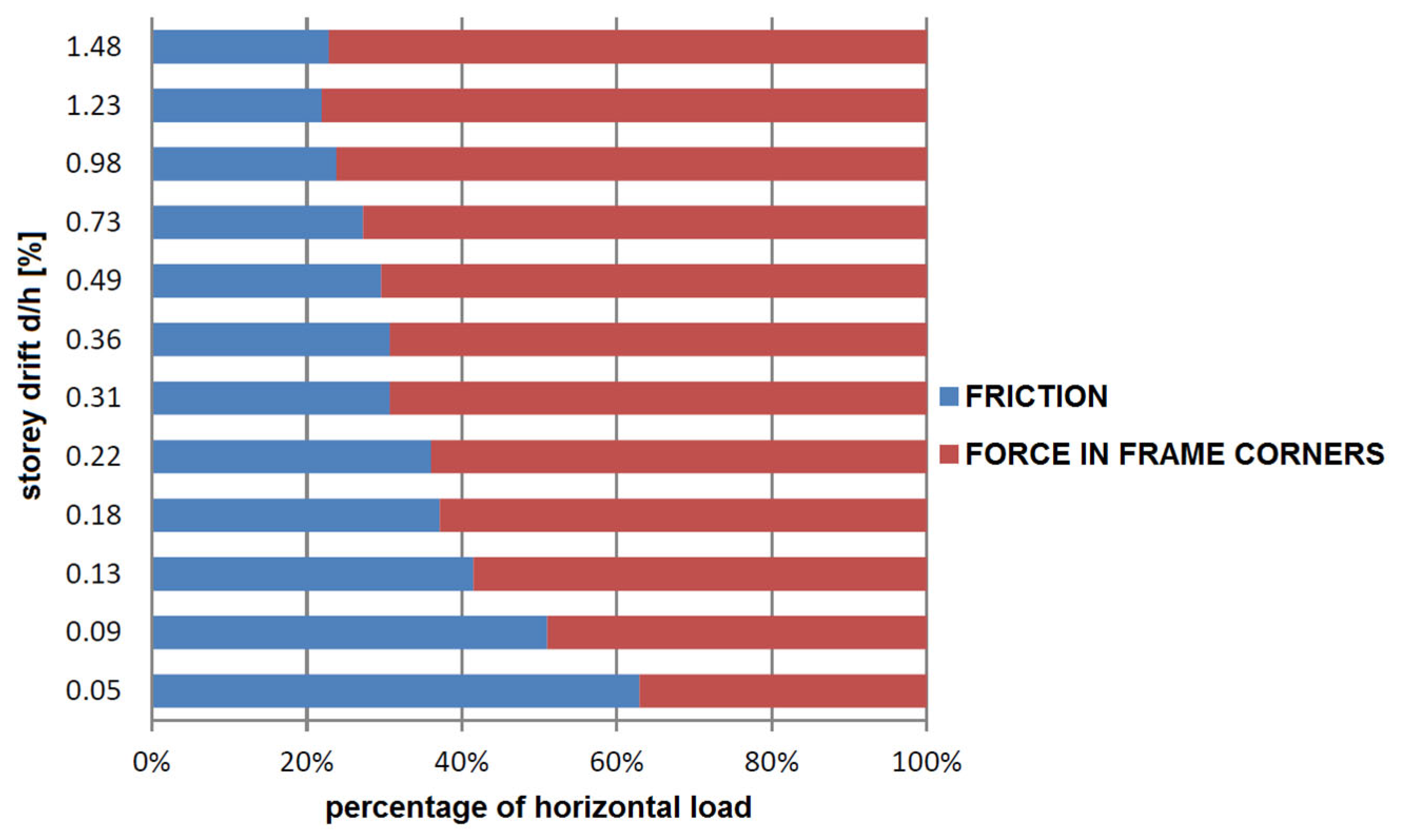
- Due to the vertical support of the timber frame lintel enabled by glass infill, frame joints are loaded in pure shear for which they have the biggest load-bearing capacity [36].
- Vertical load positively influences the lateral strength of the specimens, by 40%, due to the activation of friction between frame lintels and glass sheets.
- The number of glass sheets (single vs. double glazing) does not influence the lateral strength. The reason is that the friction force acting along the horizontal edges of the glass panel is almost the same.
- The intensity of vertical load influences strength degradation. In the case of specimens with low vertical load, the strength degradation was on average twice as high as in the cases of specimens with a high vertical load. The stiffness degradation was not influenced either by the intensity of vertical load or by the number of glazing panels.
8. Conclusions
Author Contributions
Funding
Institutional Review Board Statement
Informed Consent Statement
Data Availability Statement
Conflicts of Interest
References
- Rajcic, V.; Zarnic, R. Racking Performance of Wood-Framed Glass Panels. In Proceedings of the World Conference on Timber Engineering, Auckland, New Zealand, 15–19 July 2012; pp. 56–57. [Google Scholar]
- Rajcic, V.; Zarnic, R. Seismic Response of Timber Frames with Laminated Glass Infill. In CIB-W18/45-15-4, Proceedings of the 45th CIB-W18 Meeting, Växjo, Sweden, 27–30 August 2012; Ingenieurholzbau und Baukonstruktionen Karlsruhe Institute of Technology Germany: Växjo, Sweden, 2012; p. 11. [Google Scholar]
- Stepinac, M. Spojevi Kompozitnih Sustava Drvo-Nosivo Staklo u Potresnom Okruženju. Ph.D. Thesis, University of Zagreb, Zagreb, Croatia, 2015. [Google Scholar]
- CNR-DT 210/2013; Guide for the Design, Construction and Control of Buildings with Structural Glass Elements. CNR-Advisory Committee on Technical Recommendations for Construction: Roma, Italy, 2013.
- CEN-EN 572-1; Glass in Building—Basic Soda-Lime Silicate Glass Products—Part 1: Definitions and General Physical and Mechanical Properties. CEN: Brussels, Belgium, 2012.
- EN 14449:2005; Glass in Building—Laminated Glass and Laminated Safety Glass—Evaluation of Conformity/Product Standard. CEN: Brussels, Belgium, 2005.
- Feldmann, M.; Kasper, R.; Abeln, B.; Cruz, P.; Belis, J.; Beyer, J.; Colvin, F.E.; Eliášová, M.; Galuppi, L.; Geßler, A.; et al. Guidance for European Structural Design of Glass Components; Support to the Implementation, Harmonization and Further Development of the Eurocodes; Publications Office of the European Union: Luxembourg, 2014. [Google Scholar]
- Antolinc, D.; Žarnic, R.; Cepon, F.; Rajcic, V.; Stepinac, M. Laminated Glass Panels in Combination with Timber Frame as a Shear Wall in Earthquake Resistant Building Design. In Proceedings of the Challenging Glass 3: Conference on Architectural and Structural Applications of Glass, Delft, The Netherlands, 28–29 June 2012; pp. 623–631. [Google Scholar]
- Pascha, V.S. Architectural Application and Ecological Impact Studies of Timber-Glass Composites Structures. In Proceedings of the Engineered Transparency International Conference at Glasstec, Düsseldorf, Germany, 21–22 October 2014. [Google Scholar]
- Antolinc, D. Uporaba Steklenih Panelov Za Potresno Varno Gradnjo Objektov: Doktorska Disertacija. Ph.D. Thesis, Univerza v Ljubljani, Ljubljana, Slovenia, 2014. [Google Scholar]
- Antolinc, D.; Rajčić, V.; Žarnić, R. Analysis of Hysteretic Response of Glass Infilled Wooden Frames. Vilnius Gedim. Tech. Univ. 2014, 20, 600–608. [Google Scholar] [CrossRef]
- Stepinac, M.; Rajčić, V.; Žarnić, R. Timber-Structural Glass Composite Systems in Earthquake Environment. Gradjevinar 2016, 68, 211–219. [Google Scholar]
- Hamm, J. Development of Timber-Glass Prefabricated Structural Elements. Proc. IABSE Conf. Innov. Wooden Struct. Bridges 2001, 85, 119–124. [Google Scholar]
- Niedermaier, P. Shear-Strength of Glass Panel Elements in Combination with Timber Frame Constructions. In Proceedings of the 8th International Conference on Architectural and Automotive Glass (GPD), Tampere, Finland, 15–18 June 2003; pp. 262–264. [Google Scholar]
- Wellersho, F.; Sedlacek, G. Stabilization of Building Envelopes with the Use of the Glazing. In Proceedings of the Glass Processing Days, Tampere, Finland, 17–20 June 2005; pp. 281–283. [Google Scholar]
- Weller, B.; Schadow, T. Designing of Bonded Joints in Glass Structures. In Proceedings of the 10th International Conference on Architectural and Automotive Glass (GPD), Tampere, Finland, 15–18 June 2007. [Google Scholar]
- Mocibob, D. Glass Panel under Shear Loading-Use of Glass Envelopes in Building Stabilization. Ph.D. Thesis, Ecole Polytechnique Fédérale de Lausanne, EPFL, Lausanne, Switzerland, 2008. [Google Scholar]
- Hochhauser, W. A Contribution to the Calculation and Sizing of Glued and Embedded Timber-Glass Composite Panes. Ph.D. Thesis, Vienna University of Technology, Vienna, Austria, 2011. [Google Scholar]
- Neubauer, G. Holz-Glas-Verbundkonstruktionen. Weiterentwicklung und Herstellung von Holz-Glas-Verbundkonstruktionen Durch Statisch Wirksames Verkleben von Holz und Glas Zum Praxiseinsatz im Holzhausbau. Available online: https://glassolutions.at/sites/glassolutions.eu/files/2017-12/hgv_holzforschung_austria_als_gebaeudeaussteifung.pdf (accessed on 6 December 2021).
- Winter, W.; Hochauser, W.; Kreher, K. Load Bearing and Stiening Timber-Glass Composites. In Proceedings of the World Conference on Timber Engineering, Trento, Italy, 20–24 June 2010. [Google Scholar]
- Cruz, P.J.S.; Pequeno, J.; Lebet, J.-P.; Mocibob, D. Mechanical Modelling of In-Plane Loaded Glass Panes. In Proceedings of the Challenging Glass 2—Conference on Architectural and Structural Applications of Glass, Delft, The Netherlands, 20–21 May 2010; pp. 309–318. [Google Scholar]
- Blyberg, L.; Serrano, E.; Enquist, B.; Sterley, M. Adhesive Joints for Structural Timber/Glass Applications: Experimental Testing and Evaluation Methods. Int. J. Adhes. Adhes. 2012, 35, 76–87. [Google Scholar] [CrossRef]
- Nicklisch, F.; Dorn, M.; Weller, B.; Serrano, E. Joint Study on Material Properties of Adhesives to Be Used in Load-Bearing Timber-Glass Composite Elements. In Proceedings of the Engineered Transparency—International Conference at Glasstec, Düsseldorf, Germany, 21–22 October 2014. [Google Scholar]
- Ber, B.; Šusteršič, I.; Premrov, M.; Štrukelj, A.; Dujič, B. Testing of Timber–Glass Composite Walls. In Proceedings of the Institution of Civil Engineers-Structures and Buildings; Thomas Telford Services: London, UK, 2015; Volume 168, pp. 500–513. Available online: https://www.icevirtuallibrary.com/doi/10.1680/stbu.13.00105 (accessed on 7 January 2022).
- Amadio, C.; Bedon, C. Effect of Circumferential Sealant Joints and Metal Supporting Frames on the Buckling Behavior of Glass Panels Subjected to In-Plane Shear Loads. Glass Struct. Eng. 2016, 1, 353–373. [Google Scholar] [CrossRef] [Green Version]
- Štrukelj, A.; Ber, B.; Premrov, M. Racking Resistance of Timber-Glass Wall Elements Using Different Types of Adhesives. Constr. Build. Mater. 2015, 93, 130–143. [Google Scholar] [CrossRef]
- Ber, B.; Finžgar, G.; Premrov, M.; Štrukelj, A. On Parameters Affecting the Racking Stiffness of Timber-Glass Walls. Glass Struct. Eng. 2018, 4, 69–82. [Google Scholar] [CrossRef]
- Santarsiero, M.; Bedon, C.; Moupagitsoglou, K. Energy-Based Considerations for the Seismic Design of Ductile and Dissipative Glass Frames. Soil Dyn. Earthq. Eng. 2019, 125, 105710. [Google Scholar] [CrossRef]
- Bedon, C.; Amadio, C. Numerical Assessment of Vibration Control Systems for Multi-Hazard Design and Mitigation of Glass Curtain Walls. J. Build. Eng. 2018, 15, 1–13. [Google Scholar] [CrossRef] [Green Version]
- Žarnić, R.; Tsionis, G.; Gutierrez, E.; Pinto, A.; Geradin, M.; Dimova, S. Purpose and Justification for New Design Standards Regarding the Use of Glass Products in Civil Engineering Works-Publications Office of the EU. Available online: https://op.europa.eu/hr/publication-detail/-/publication/9ae98636-ec59-4560-8e14-a650a2fec188 (accessed on 7 December 2021).
- Stepinac, M.; Rajcic, V.; Tomasi, R.; Hunger, F.; van de Kuilen, J.-W.G.; Serrano, E. Comparison of Design Rules for Glued-in Rods and Design Rule Proposal for Implementation in European Standards. In Proceedings of the CIB-W18 Timber Structures, Meeting 46, Vancouver, BC, Canada, 26–29 August 2013. [Google Scholar]
- Neugebauer, J.; Larcher, M.; Rajcic, V.; Zarnic, R. Activity Report of COST Action TU0905 Working Group 1-Predicting Complex Loads on Glass Structures. In Proceedings of the Challenging Glass 4 & COST Action TU0905 Final Conference, Lausanne, Switzerland, 6–7 February 2014; pp. 11–20. [Google Scholar]
- Bedon, C.; Amadio, C. Flexural–Torsional Buckling: Experimental Analysis of Laminated Glass Elements. Eng. Struct. 2014, 73, 85–99. [Google Scholar] [CrossRef]
- EN 1998-1; Eurocode 8: Design of Structures for Earthquake Resistance–Part 1: General Rules, Seismic Actions and Rules for Buildings. CEN: Brussels, Belgium, 2004.
- Krstevska, L.; Tashkov, L.; Rajcic, V.; Zarnic, R. Shaking Table Test of Innovative Composite Panel Composed of Glued Laminated Wood and Bearing Glass. In Proceedings of the 15th World Conference on Earthquake Engineering, Lisbon, Portugal, 24–28 September 2012; pp. 1–10. [Google Scholar]
- Žarnić, R.; Rajčić, V.; Kržan, M. Response of Laminated Glass-CLT Structural Components to Reverse-Cyclic Lateral Loading. Constr. Build. Mater. 2020, 235, 117509. [Google Scholar] [CrossRef]
- Barbalić, J.; Rajčić, V.; Žarnic, R. Numerical Evaluation of Seismic Capacity of Structures with Hybrid Timber-Glass Panels. In Proceedings of the World Conference on Timber Engineering (WCTE), Vienna, Austria, 22–25 August 2016. [Google Scholar]
- EN 12150-1:2015+A1:2019-Glass in Building-Thermally Toughened Soda Lime Silicate Safety Glass. Available online: https://standards.iteh.ai/catalog/standards/cen/d6f942f1-f173-4a45-bcb5-ccb6e0df280d/en-12150-1-2015a1-2019 (accessed on 7 January 2022).
- EN 14179-1:2016-Glass in Building-Heat Soaked Thermally Toughened Soda Lime Silicate Safety. Available online: https://standards.iteh.ai/catalog/standards/cen/f97d0a10-fe69-491b-aa45-7e8ff3d11a9e/en-14179-1-2016 (accessed on 7 January 2022).
- DIN 1249-11 -Glass in Building-Part 11: Glass Edges-Terms and Definitions, Characteristics of Edge Types and Finishes. Available online: https://www.en-standard.eu/din-1249-11-glass-in-building-part-11-glass-edges-terms-and-definitions-characteristics-of-edge-types-and-finishes/ (accessed on 7 December 2021).
- EN 16351:2015-Timber Structures-Cross Laminated Timber-Requirements. Available online: https://standards.iteh.ai/catalog/standards/cen/cbfe13a0-c6c2-4c1c-9e7f-d6c46155e3e9/en-16351-2015 (accessed on 7 January 2022).
- EN 14080:2013-Timber Structures-Glued Laminated Timber and Glued Solid Timber-Requirements. Available online: https://standards.iteh.ai/catalog/standards/cen/f5a36e99-021d-44cb-8dec-9e41df42d7a5/en-14080-2013 (accessed on 7 January 2022).
- EN 14081-1:2016+A1:2019-Timber Structures-Strength Graded Structural Timber with Rectangular. Available online: https://standards.iteh.ai/catalog/standards/cen/f0f4bbff-b863-4571-98f6-364add96ae79/en-14081-1-2016a1-2019 (accessed on 7 January 2022).
- ISO 7500-1:2018-Metallic Materials—Calibration and Verification of Static Uniaxial Testing Machines—Part 1: Tension/Compression Testing Machines—Calibration and Verification of the Force-Measuring System. Available online: https://www.iso.org/standard/72572.html (accessed on 9 December 2021).
- ISO 9513:2012-Metallic Materials—Calibration of Extensometer Systems Used in Uniaxial Testing. Available online: https://www.iso.org/standard/41619.html (accessed on 9 December 2021).
- ANSYS®. Academic Teaching Mechanical. ANSYS Workbench User’s Guide; ANSYS, Inc.: Canonsburg, PA, USA, 2009. [Google Scholar]
- ANSYS®. ANSYS Theory Reference; SAS IP, Inc.: Canonsburg, PA, USA, 1999. [Google Scholar]
- Ansys, Inc. ANSYS Meshing User’s Guide. Renew. Sustain. Energy Rev. 2011, 80, 724–746. [Google Scholar]


| Specimen Type | Dimensions (mm) | Edge Processing Acc. To DIN 1249-11 | Number of Specimens |
|---|---|---|---|
| Laminated glass—2 mm × 6 mm | 200 × 400 | Bordered edge | 3 |
| Laminated glass—2 mm × 10 mm | 200 × 400 | Bordered edge | 3 |
| Insulated (IZO) glass—4 mm × 6 mm | 200 × 400 | Bordered edge | 3 |
| Insulated (IZO) glass—4 mm × 10 mm | 200 × 400 | Bordered edge | 3 |
| (2 mm × 6 mm) × 2—Laminated glass and wooden slat | 200 × 400 | Bordered edge | 3 |
| (2 mm × 10 mm) × 2—Laminated glass and wooden slat | 200 × 400 | Bordered edge | 3 |
| Laminated glass—2 mm × 10 mm smooth ground edges | 200 × 400 | Smooth ground edge | 3 |
| Properties | Value |
|---|---|
| E—Young’s elasticity modulus | 70,000 N/mm2 |
| G—Shear modulus | 28.689 N/mm2 |
| μ—Poisson’s ratio | 0.22 |
| α—thermal expansion coefficient | 8.8 × 10⁻⁶ |
| ρ—density | 2.5 g/cm3 |
| Compressive strength | 700–1000 N/mm2 |
| Tensile strength | 30–45 N/mm2 |
| Properties | Index | Value |
|---|---|---|
| Density | ρ | 420 kg/m3 |
| Young’s modulus of elasticity | Ex | 11,000 Mpa |
| EyEz | 600 Mpa 580 Mpa | |
| Shear modulus | Gxy | 600 Mpa |
| Gxz | 690 Mpa | |
| Gyz | 580 Mpa | |
| Poisson’s ratio | νxy | 0.3 |
| νxz | 0.25 | |
| νyz | 0.6 |
| Strength | Index | Value |
|---|---|---|
| Bending | fm,k | 24 Mpa |
| Tension (parallel to the grain) | ft,0, k | 14 Mpa |
| Tension (perpendicular to the grain) | ft,90, k | 0.5 Mpa |
| Compression (parallel to the grain) | ft,0, k | 21 Mpa |
| Tension (perpendicular to the grain) | ft,90, k | 2.5 Mpa |
| Shear | fv,k | 2.5 Mpa |
| Specimen Type | Frictional Stress—Lateral Load 2 kN (N/mm2) | Deviation (%) | |
|---|---|---|---|
| Experimental Work | ANSYS | ||
| Laminated glass—2 mm × 6 mm | 0.25 | 0.25 | 0 |
| Laminated glass—2 mm × 10 mm | 0.10 | 0.10 | 0 |
| IZO glass—4 mm × 6 mm | 0.07 | 0.072 | 2.8 |
| IZO glass—4 mm × 10 mm | 0.04 | 0.041 | 2.5 |
| (2 mm × 6 mm) × 2—Laminated glass and wooden slat | 0.07 | 0.072 | 2.8 |
| (2 mm × 10 mm) × 2—Laminated glass and wooden slat | 0.05 | 0.051 | 2 |
| Laminated glass—2 mm × 10 mm- smooth ground edges | 0.09 | 0.093 | 3.3 |
Publisher’s Note: MDPI stays neutral with regard to jurisdictional claims in published maps and institutional affiliations. |
© 2022 by the authors. Licensee MDPI, Basel, Switzerland. This article is an open access article distributed under the terms and conditions of the Creative Commons Attribution (CC BY) license (https://creativecommons.org/licenses/by/4.0/).
Share and Cite
Rajčić, V.; Perković, N.; Damjanović, D.; Barbalić, J. Influence of Friction on the Behavior and Performance of Prefabricated Timber–Bearing Glass Composite Systems. Sustainability 2022, 14, 1102. https://doi.org/10.3390/su14031102
Rajčić V, Perković N, Damjanović D, Barbalić J. Influence of Friction on the Behavior and Performance of Prefabricated Timber–Bearing Glass Composite Systems. Sustainability. 2022; 14(3):1102. https://doi.org/10.3390/su14031102
Chicago/Turabian StyleRajčić, Vlatka, Nikola Perković, Domagoj Damjanović, and Jure Barbalić. 2022. "Influence of Friction on the Behavior and Performance of Prefabricated Timber–Bearing Glass Composite Systems" Sustainability 14, no. 3: 1102. https://doi.org/10.3390/su14031102
APA StyleRajčić, V., Perković, N., Damjanović, D., & Barbalić, J. (2022). Influence of Friction on the Behavior and Performance of Prefabricated Timber–Bearing Glass Composite Systems. Sustainability, 14(3), 1102. https://doi.org/10.3390/su14031102