
Safety Analysis and Emergency Response of Suspended Oil and Gas Pipelines Triggered by Natural Disasters


Abstract
1. Introduction
2. Materials and Methods
3. FEM Analysis Results
3.1. The Effects of Suspended Lengths
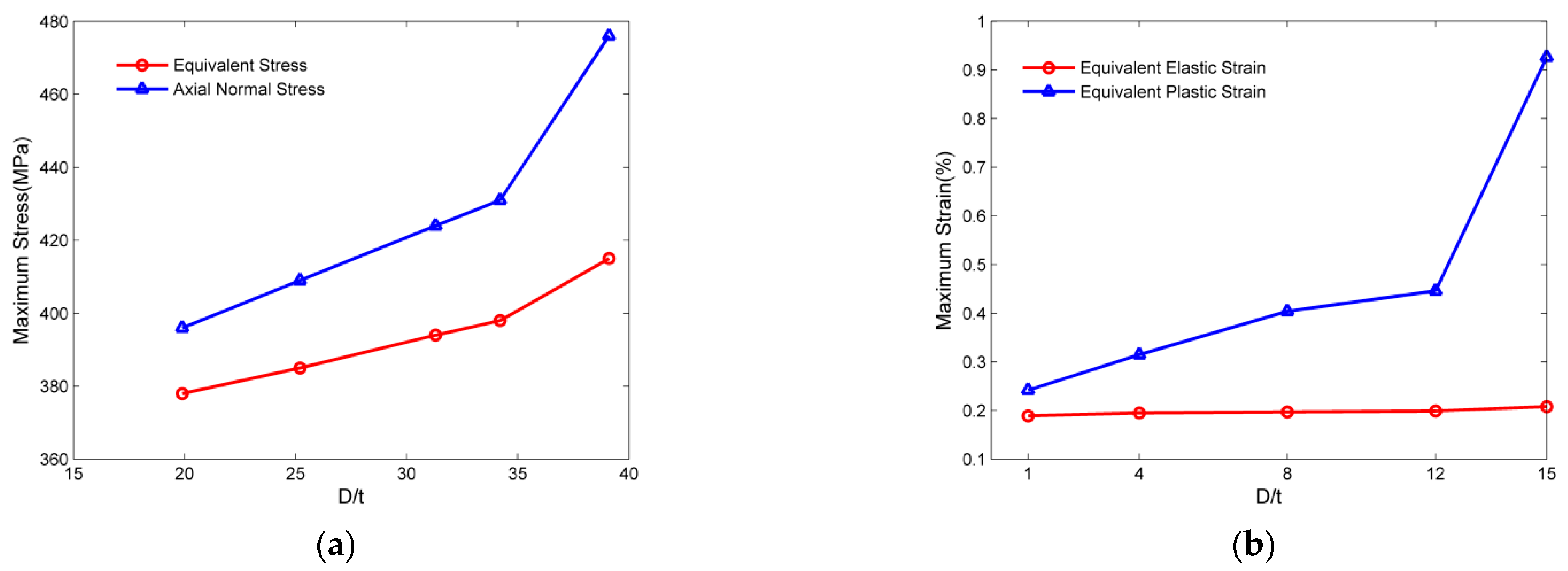
3.2. The Effects of D/t
3.3. The Effects of Operating Pressure
3.4. The Effects of the Fluid Gravity
4. Emergency Response to Suspended Pipelines Caused by Natural Disasters
4.1. Emergency Decision Criteria
4.2. Emergency Levels and Treatment Measures
5. Conclusions
- (1)
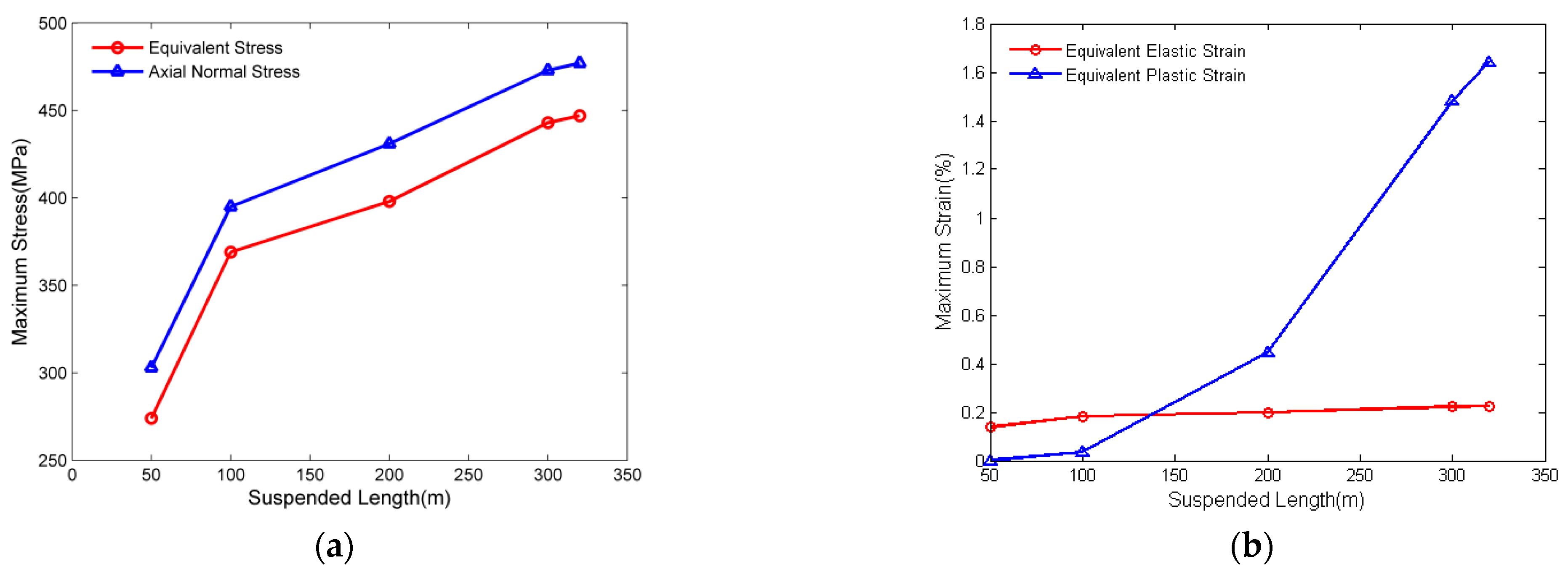
- The finite element results show that the case pipeline with 320 m suspended length is in a high-risk status with a 447 MPa equivalent stress and 1.8% total strain at the critical locations.
- (2)
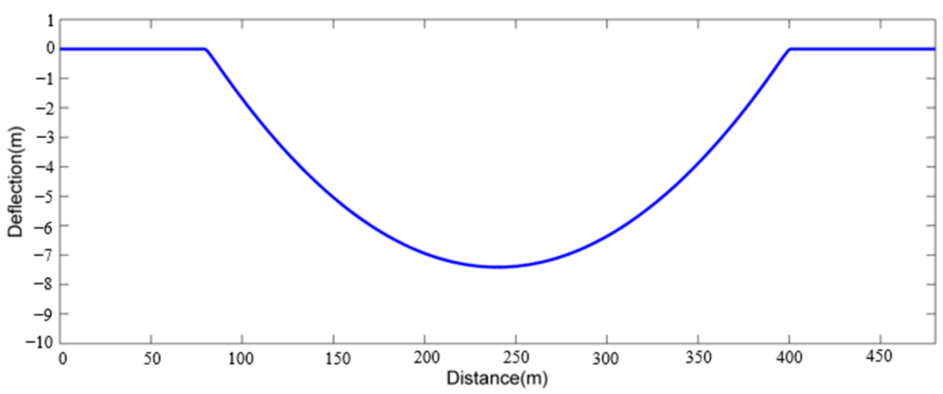
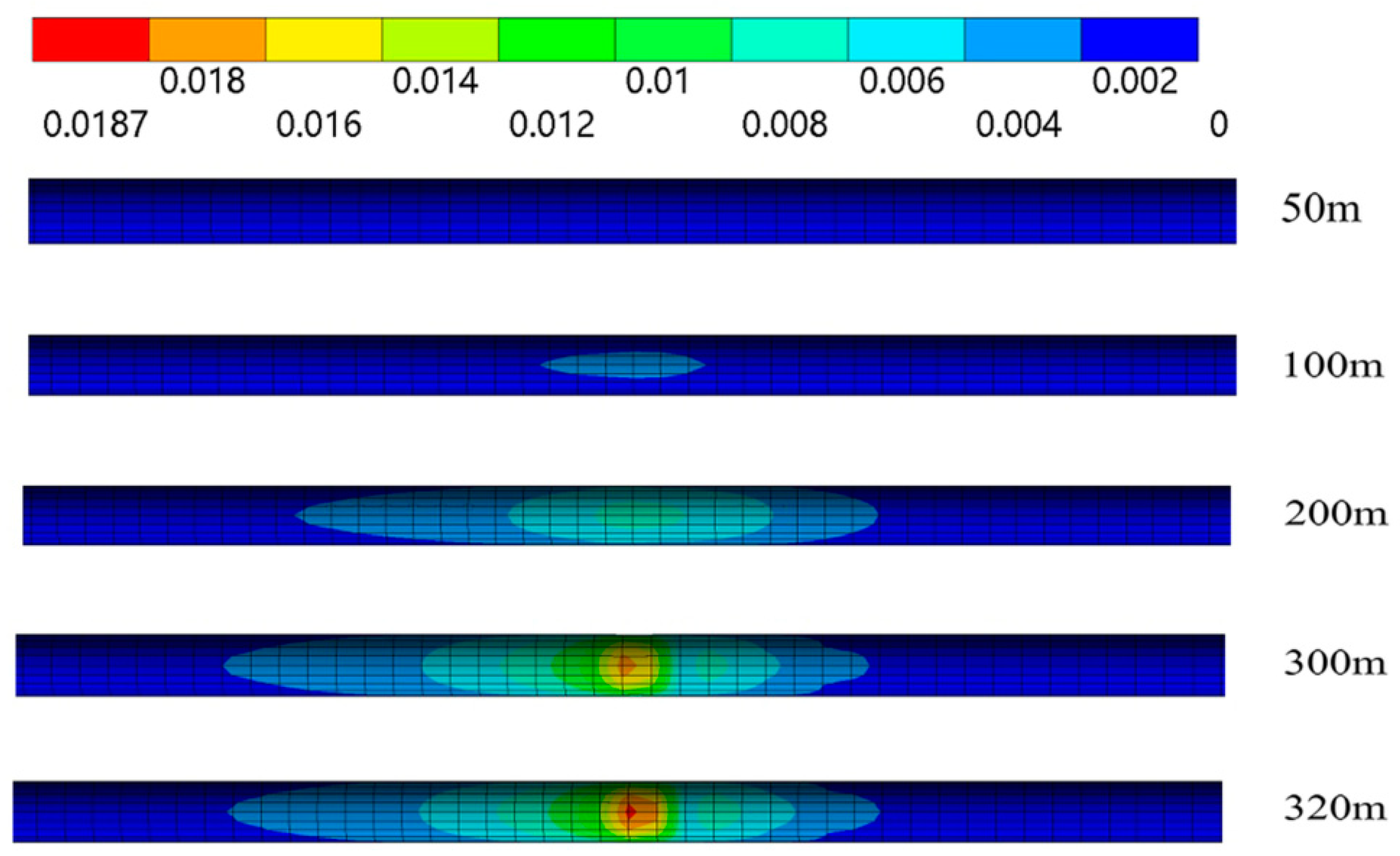
- The stress, strain, and deflection are symmetrical along the perpendicular bisector of the pipeline. Both the maximum stress and strain appear at the ends of the suspended section, which are defined as critical locations, and the safety of suspended pipelines depends on the locations.
- (3)
- The factors of suspended length, the ratio of diameter to thickness, the internal pressure, and the fluid inside the pipe influence the safety of suspended pipelines. The pipeline stress, strain, and deflection increase with increasing these factors. The suspended length is the most critical factor for the safety of the suspended pipeline.
- (4)
- The irreversible plastic strain occur if the suspended length exceeds 50 m and becomes dominant when the length exceeds 150 m, and the total strain reaches 2% when the suspended length is 340 m.
- (5)
- An emergency plan with four emergency levels based on plastic strain and suspended length is developed to deal with different suspended pipelines caused by natural disasters.
- (6)
- This study only considers the X52 steel, and thus, other steels such as x70 and x80 may be considered in the future. Additionally, the coupling effects of different natural disasters and hazardous scenarios may also be considered to improve the application of this study. In addition, this study may be extended to analyze submarine pipelines by changing the model parameters such as loads and boundary conditions.
Author Contributions
Funding
Conflicts of Interest
References
- Dale, S. BP Statistical Review of World Energy 2022; World Petroleum Congress: London, UK, 2022. [Google Scholar]
- Li, X.; Zhang, Y.; Abbassi, R.; Khan, F.; Chen, G. Probabilistic fatigue failure assessment of free spanning subsea pipeline using dynamic Bayesian network. Ocean. Eng. 2021, 234, 109323. [Google Scholar] [CrossRef]
- Chen, C.; Li, C.; Reniers, G.; Yang, F. Safety and security of oil and gas pipeline transportation: A systematic analysis of research trends and future needs using WoS. J. Clean. Prod. 2021, 279, 123583. [Google Scholar] [CrossRef]
- Zhang, M.; Ling, J.; Tang, B.; Dong, S.; Zhang, L. A Data-Driven Based Method for Pipeline Additional Stress Prediction Subject to Landslide Geohazards. Sustainability 2022, 14, 11999. [Google Scholar] [CrossRef]
- Wang, Y.; Li, R.; Xia, A.; Ni, P.; Qin, G. An integrated modeling method of uncertainties: Application-orientated fuzzy random spatiotemporal analysis of pipeline structures. Tunn. Undergr. Space Technol. 2023, 131, 104825. [Google Scholar] [CrossRef]
- Wang, Y.; Xia, A.; Qin, G. Probabilistic modeling for reliability analysis of buried pipelines subjected to spatiotemporal earthquakes. Probabilistic Eng. Mech. 2022, 69, 103315. [Google Scholar] [CrossRef]
- The Xinhua News Agency. Serious Risk in Shiting River Section of Lanzhou-Chengdu-Chongqing Refined Oil Pipeline Caused by Rainstorm in Sichuan. 2013. Available online: http://www.gov.cn/jrzg/2013-07/13/content_2447010.htm (accessed on 6 December 2022).
- Qilu Evening News. The Gas Pipeline Near a Gas Station Leaked Suddenly Due to Ground Subsidence. Available online: https://www.chinanews.com/sh/2014/03-06/5918827.shtml (accessed on 5 December 2022).
- Shittu, A.A.; Kara, F.; Aliyu, A.; Unaeze, O. Review of pipeline span analysis. World J. Eng. 2019, 16, 166–190. [Google Scholar] [CrossRef]
- Wu, X.N.; Lu, H.F.; Wu, S.J.; Kun, H.; Chen, X.; Kang, F.X.; Liu, Z.L. Analysis of Suspended Pipeline Stress Sensitivity. Appl. Mech. Mater. 2014, 501–504, 2331–2334. [Google Scholar] [CrossRef]
- Zhang, L.; Xie, Y.; Yan, X.; Yang, X. An elastoplastic semi-analytical method to analyze the plastic mechanical behavior of buried pipelines under landslides considering operating loads. J. Nat. Gas Sci. Eng. 2016, 28, 121–131. [Google Scholar] [CrossRef]
- Peng, S.; Luo, Y. Determination of stress field in buried thin pipelines resulting from ground subsidence due to longwall mining. Min. Sci. Technol. 1988, 6, 205–216. [Google Scholar] [CrossRef]
- Cao, Z.; Zhou, Y.; Xu, P.; Li, J. Mechanical Response Analysis and Safety Assessment of Shallow-Buried Pipeline under the Influence of Mining. CMES Comput. Model. Eng. Sci. 2014, 101, 351–364. [Google Scholar]
- Karamitros, D.; Bouckovalas, G.; Kouretzis, G.; Gkesouli, V. An analytical method for strength verification of buried steel pipelines at normal fault crossings. Soil Dyn. Earthq. Eng. 2011, 31, 1452–1464. [Google Scholar] [CrossRef]
- Hendriks, M.A.; ‘t Hart, C.M.P.; Frissen, C.M. Elasto-plastic design and assessment of pipelines: 3D finite element modeling. In Proceedings of the ASCE Pipeline Division Specialty Congress-Pipeline Engineering and Construction, San Diego, CA, USA, 1–4 August 2004; pp. 923–932. [Google Scholar]
- Trifonov, O.V.; Cherniy, V.P. Elastoplastic stress–strain analysis of buried steel pipelines subjected to fault displacements with account for service loads. Soil Dyn. Earthq. Eng. 2012, 33, 54–62. [Google Scholar] [CrossRef]
- Trifonov, O.V.; Cherniy, V.P. A semi-analytical approach to a nonlinear stress–strain analysis of buried steel pipelines crossing active faults. Soil Dyn. Earthq. Eng. 2010, 30, 1298–1308. [Google Scholar] [CrossRef]
- Zhang, Z.; Lv, X.; Mao, M.; Pan, Y.; Fang, L.; Wu, Z. Mechanical response for rainfall-induced landslides on jointed gas pipelines. Comput. Geotech. 2022, 146, 104708. [Google Scholar] [CrossRef]
- Liao, K.; Li, Y.; Yao, Q. Calculation and Analysis for Critical Parameters of Long-Span Suspended Pipeline Stress Deformation Area. In Proceedings of the International Conference on Pipelines and Trenchless Technology 2011, Beijing, China, 26–29 October 2011; American Society of Civil Engineers: Reston, VA, USA, 2011. [Google Scholar]
- Zhao, K.; Xiong, H.; Chen, G.; Zhao, D.; Chen, W.; Du, X. Wave-induced dynamics of marine pipelines in liquefiable seabed. Coast. Eng. 2018, 140, 100–113. [Google Scholar] [CrossRef]
- Wang, Q.; Bian, J.; Huang, W.; Lu, Q.; Zhao, K.; Li, Z. Seabed Liquefaction around Pipeline with Backfilling Trench Subjected to Strong Earthquake Motions. Sustainability 2022, 14, 12825. [Google Scholar] [CrossRef]
- Huang, Y.; Qin, G.; Hu, G. Failure pressure prediction by defect assessment and finite element modelling on pipelines containing a dent-corrosion defect. Ocean Eng. 2022, 266, 112875. [Google Scholar] [CrossRef]
- Wang, X.; Shuai, J.; Ye, Y.; Zuo, S. Investigating the Effects of Mining Subsidence on Buried Pipeline Using Finite Element Modeling. In Proceedings of the 2008 7th International Pipeline Conference: American Society of Mechanical Engineers, Calgary, AB, Canada, 29 September–3 October 2008; pp. 601–606. [Google Scholar]
- Zakeri, A. Submarine debris flow impact on suspended (free-span) pipelines: Normal and longitudinal drag forces. Ocean Eng. 2009, 36, 489–499. [Google Scholar] [CrossRef]
- Shao, B.; Yan, X.Z.; Yang, X.J. Nonlinear Dynamic Response and Safety Analysis of Suspended Submarine Pipeline. Appl. Mech. Mater. 2011, 121–126, 3366–3370. [Google Scholar] [CrossRef]
- Kunert, H.; Otegui, J.; Marquez, A. Nonlinear FEM strategies for modeling pipe–soil interaction. Eng. Fail. Anal. 2012, 24, 46–56. [Google Scholar] [CrossRef]
- Zhang, Y.; Yi, D.; Xiao, Z.; Huang, Z. Engineering critical assessment for offshore pipelines with 3-D elliptical embedded cracks. Eng. Fail. Anal. 2015, 51, 37–54. [Google Scholar] [CrossRef]
- Saeedzadeh, R.; Hataf, N. Uplift response of buried pipelines in saturated sand deposit under earthquake loading. Soil Dyn. Earthq. Eng. 2011, 31, 1378–1384. [Google Scholar] [CrossRef]
- Zheng, J.; Zhang, B.; Liu, P.; Wu, L. Failure analysis and safety evaluation of buried pipeline due to deflection of landslide process. Eng. Fail. Anal. 2012, 25, 156–168. [Google Scholar] [CrossRef]
- Zhang, J.; Liang, Z.; Han, C. Buckling behavior analysis of buried gas pipeline under strike-slip fault displacement. J. Nat. Gas Sci. Eng. 2014, 21, 921–928. [Google Scholar] [CrossRef]
- Liu, X.; Ai, Z.; Qi, J.; Wang, S.; Qin, H.; Qian, H. Mechanics analysis of pipe lifting in horizontal directional drilling. J. Nat. Gas Sci. Eng. 2016, 31, 272–282. [Google Scholar] [CrossRef]
- Vazouras, P.; Dakoulas, P.; Karamanos, S.A. Pipe–soil interaction and pipeline performance under strike–slip fault movements. Soil Dyn. Earthq. Eng. 2015, 72, 48–65. [Google Scholar] [CrossRef]
- Mehrjardi, G.T.; Karimi, M. Numerical Modeling of Buried Steel Pipe Subjected to Impact Load. J. Pipeline Syst. Eng. Pract. 2021, 12, 04021048. [Google Scholar] [CrossRef]
- Ma, H.; He, B.; Luo, X.; Cai, W.; Liu, D.; Hou, C.; Han, J. Investigation on strain characteristic of buried natural gas pipeline under longitudinal landslide debris flow. J. Nat. Gas Sci. Eng. 2021, 86, 103708. [Google Scholar] [CrossRef]
- Cheng, P.; Guo, J.; Yao, K.; Liu, C.; Liu, X.; Liu, F. Uplift Behavior of Pipelines Buried at Various Depths in Spatially Varying Clayey Seabed. Sustainability 2022, 14, 8139. [Google Scholar] [CrossRef]
- Tsatsis, A.; Alvertos, A.; Gerolymos, N. Fragility analysis of a pipeline under slope failure-induced displacements occurring parallel to its axis. Eng. Struct. 2022, 262, 114331. [Google Scholar] [CrossRef]
- Wu, Y.; Meng, B.; Wang, L.; Qin, G. Seismic vulnerability analysis of buried polyethylene pipeline based on finite element method. Int. J. Press. Vessel. Pip. 2020, 187, 104167. [Google Scholar] [CrossRef]
- Zheng, T.; Liang, Z.; Zhang, L.; Tang, S.; Cui, Z. Safety assessment of buried natural gas pipelines with corrosion defects under the ground settlement. Eng. Fail. Anal. 2021, 129, 105663. [Google Scholar] [CrossRef]
- Lawrence, K.L. ANSYS Workbench Tutorial Release 14; SDC Publications: Mission, KS, USA, 2012. [Google Scholar]
- Shi, Z. Power Pipeline Design Manual; China Machine Press: Beijing, China, 2006. [Google Scholar]
- Institute ANS. Pipeline Transportation Systems for Liquid Hydrocarbons and Other Liquids; American Society of Mechanical Engineers: New York, NY, USA, 2012. [Google Scholar]
- Institute ANS. Gas Transmission and Distribution Piping Systems; American Society of Mechanical Engineers: New York, NY, USA, 2012. [Google Scholar]


| Parameters (Units) | Values |
|---|---|
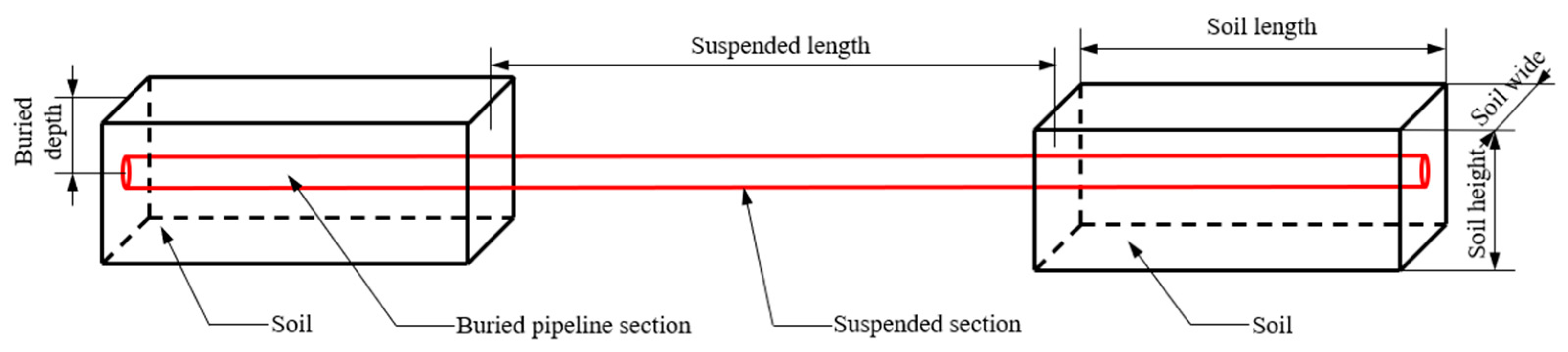
| Soil length (m) | 80 |
| Soil depth (m) | 2 |
| Suspended length (m) | 320 |
| Pipeline diameter (mm) | 219.1 |
| Internal pressure (MPa) | 4 |
| Oil density (kg/m3) | 840 |
| Pipeline material | X52 steel (API) |
| Yield strength (MPa) | 375 |
| Poisson’s ratio | 0.3 |
| Elastic modulus (E) | 203 |
| Ρs (kg/m3) | Es (Mpa) | υs | c (kPa) | φ (°) | ψ (°) |
|---|---|---|---|---|---|
| 1450 | 40 | 0.4 | 30 | 12.3 | 0 |
| Emergency Levels | Descriptions | Treatment Measures |
|---|---|---|
| I l < 50 m | Low risk, no plastic strain. | Normal transportation operations, refill the soil in the suspended section. |
| II 50 m≤ l < 150 m | Medium risk, there are elastic strain and plastic strain, while mainly elastic deformation. | Stop transportation operations and refill the soil in the suspended section as soon as possible. |
| III 150 m≤ l < 340 m | High-risk, plastic strain is dominant but the strain is less than 2%. | Stop transportation operations, replace the suspended pipe, and refill the soil in the suspended section. |
| IV l ≥ 340 m | Very high risk, with a strain larger than 2%, and even causes oil leakage, fire, and explosion. | Stop transportation operations, evacuate surrounding people, prepare for leakage rescue, fill the soil in the suspended section, and replace the suspended pipe. |
Publisher’s Note: MDPI stays neutral with regard to jurisdictional claims in published maps and institutional affiliations. |
© 2022 by the authors. Licensee MDPI, Basel, Switzerland. This article is an open access article distributed under the terms and conditions of the Creative Commons Attribution (CC BY) license (https://creativecommons.org/licenses/by/4.0/).
Share and Cite
Yu, J.; Chen, C.; Li, C. Safety Analysis and Emergency Response of Suspended Oil and Gas Pipelines Triggered by Natural Disasters. Sustainability 2022, 14, 17045. https://doi.org/10.3390/su142417045
Yu J, Chen C, Li C. Safety Analysis and Emergency Response of Suspended Oil and Gas Pipelines Triggered by Natural Disasters. Sustainability. 2022; 14(24):17045. https://doi.org/10.3390/su142417045
Chicago/Turabian StyleYu, Jin, Chao Chen, and Changjun Li. 2022. "Safety Analysis and Emergency Response of Suspended Oil and Gas Pipelines Triggered by Natural Disasters" Sustainability 14, no. 24: 17045. https://doi.org/10.3390/su142417045
APA StyleYu, J., Chen, C., & Li, C. (2022). Safety Analysis and Emergency Response of Suspended Oil and Gas Pipelines Triggered by Natural Disasters. Sustainability, 14(24), 17045. https://doi.org/10.3390/su142417045