Article

Characteristics of Roof Collapse of Mining Tunnels in the Fault Fracture Zone and Distribution of the Boundary Force of the Accumulation Body

1
Key Laboratory of Mining Engineering, Heilongjiang University of Science and Technology, Harbin 150022, China
2
College of Mining Engineering, Heilongjiang University of Science and Technology, Harbin 150022, China
3
College of Safety Engineering, Heilongjiang University of Science and Technology, Harbin 150022, China
*
Author to whom correspondence should be addressed.
Sustainability 2022, 14(24), 16811; https://doi.org/10.3390/su142416811
Submission received: 13 October 2022 / Revised: 28 November 2022 / Accepted: 12 December 2022 / Published: 14 December 2022
(This article belongs to the Special Issue Hazard Control and Emergency Rescue in Underground Engineering)

Abstract

:
Under the influence of coal mining, the gravel in mining tunnel sections of a fault fracture zone is prone to collapse, and the collapse accumulation body will block the tunnel, which has a very adverse influence on the safety production of coal mining and the evacuation of personnel after underground disasters. The macroscopic and mechanical characteristics of the collapse accumulation body have been studied extensively in previous works. The purpose of this paper is to provide theoretical support and reference for the rapid excavation of the tunnel blocked by the collapse accumulation body in the fault fracture zone. Taking the fault fracture zone in the tunnel as the research background, the physical characteristics and boundary mechanical characteristics of the collapse accumulation body in the fault fracture zone are studied by the method of combining on-site investigation and theoretical analysis. The results show that the force acting on the boundary on both sides of the accumulation body is passive resistance from the side wall, which is derived from the slip effect of the accumulation body slope. Similarly, the unstable boundary of the fault fracture zone caused by tunnel instability is elliptical, and the overlying load of the rescue channel to be excavated in the accumulation body is limited. On the basis of the collapse instability dimensions of the broken zone of the tunnel surrounding the rock, the calculation formulas of the height of the accumulation body and the horizontal force at the boundary were established, respectively, under two conditions of whether the collapse space was filled, and whether the curve relationship between the distribution of the horizontal force at the boundary of the accumulation body and the buried depth in the accumulation body was obtained.

1. Introduction

In recent years, the depth of coal mining is increasing year by year, and coal mine dynamic disasters occur frequently under the action of crustal stress [1,2]. However, when the mining tunnel passes through the fault fracture zone, the crushed stone in the fracture zone is prone to collapse under the mining influence, thus blocking the tunnel. According to coal mine disasters rescue statistics, less than 10% of people died instantly at the first scene of major underground disasters, while the majority of the rest were asphyxiated due to gas poisoning or blocking of escape routes [3]. At this time, the accumulation in tunnels becomes the key point restricting rescue work.
Scholars have studied this from different aspects. In terms of mining tunnel collapse, in reference [4], the structural characteristics of the collapsed accumulation body after a coal mine disaster were analyzed, the process of excavation of the blocked roadway accumulation body was simulated by using CDEM software, and the structural change characteristics of the accumulation body in the excavation process were obtained. Reference [5], based on RETPs theoretical model and energy evolution law, proposed a new method to determine the height and damaged area of roadway roof collapse zones. Reference [6], based on the Griffith energy theory and variational principle, analyzed the instability mechanism and development stage of the roadway side wall. The deformation and failure characteristics of deep-buried roadways surrounding rock under the influence of different factors were obtained in reference [7], and the stress concentration area of roadway surrounding rock was obtained by electromagnetic radiation and other monitoring means. Reference [8] used the particle discrete element method to establish the roadway model and analyzed the disaster mechanism of the instability of the roadway roof impact. When there is a fault fracture zone, as seen in reference [9], the 3D diffraction imaging method is proposed, which can reconstruct the whole region of the fracture zones and the orientation of each fracture in detail, reliably. In reference [10], from the perspective of energy, combined with uniaxial compression and the PFC numerical simulation test, the characteristics of crack development and energy release in different failure stages of rock were analyzed. In reference [11], a set of laboratory simulation methods for the fault fracture zone were proposed to explore the supporting effect of bolt with different pre-tightening forces on the fault fracture zone, and the variation characteristics of the bolt axial force under uniaxial compression of a large-scale specimen were obtained. Reference [12] took a roadway as an example, studied the large deformation mechanism of the roadway crossing the fault fracture zone, and compared and analyzed the control effect of different reinforcement methods. Reference [13], by comparing the deformation within the fault transfer zone, concluded that the fluid flow and permeability may be significantly enhanced when the fracture intensity is higher. In reference [14], a theoretical model was proposed to predict the degradation trend of shear strength of the fault fracture zone under cyclic dynamic and static loads. Reference [15] analyzed the collapse characteristics of a mining roadway in the fault fracture zone after a gas explosion, which was of guide value for the rescue work. In terms of shear slip of rock, reference [16] showed that the dynamic strength of coal mass under a dynamic load presents a “double peak” mode, and the rupture time of coal is accurately detected by acoustic emission. In reference [17], the discrete element method (DEM) was used to study the influence of fracture surface roughness on the shear strength, slip stability, and permeability evolution of underground faults or fractures after they are reactivated by fluid. In reference [18], PFC2D was used to analyze the failure mechanism of the sample under shear strength, and the influence of boundary conditions on the results of direct shear tests was obtained. In reference [19], PFC2D software was used to model, and combined with the distinct element method (DEM), the shear response of fully grouted rock bolts was successfully predicted. A new SPST scheme was proposed to further analyze the mechanical behavior of bolted rock joints subjected to simultaneous pull–shear loading. In reference [20], a new method of modeling polycrystalline rocks with a cohesive grain was proposed. The effect of the roughness coefficient of rock joints on the damage of the joints and shear mechanism were obtained under a constant load. In the stability control of crushed rock and surrounding rock of a broken roadway, reference [21] combined the broken rock mass pressure model and the permeability evolution model of compacted rock mass to study the evolution of permeability in the compression process of a broken rock mass. They concluded that the fully compacted gob can be treated as an intact rock mass. Reference [22], aiming at the problem of poor stability of surrounding rock, studied the structure and fracture distribution of a roadway roof. They proposed steel brackets support as the secondary support. Reference [23] studied the bearing capacity of a weakly cemented rock mass with different rock particle sizes and rock gradations under the conditions of secondary loading, an internal load-bearing network of the rock mass, and the cementation regeneration mechanism. Reference [24] obtained the stress concentration position of a roadway with high stress and large-sectioned broken surrounding rock. They also used the FLAC3D simulation software to compare and analyze the combined support method to the roadway surrounding rock support. In reference [25], a certain particle size of coral gravel soil was obtained, which can be used as a useful parameter to evaluate the shear strength of undisturbed coral gravel soil. Reference [26] established a water inrush solid coupling model for roadway excavation and analyzed the change laws of the stress field, displacement field, and seepage field of the surrounding rock.
Experts have carried out a lot of research surrounding the above four aspects; however, there is little research on the collapse accumulation body when a mining tunnel passes through a fault fracture zone. Therefore, in order to unblock the rescue channel quickly, the collapse characteristics of mining tunnel sections and the physical and boundary mechanical characteristics of a collapse accumulation body in a fault fracture zone should be understood first. It provides a theoretical basis for the subsequent rescue roadway excavation and the optimization and determination of the surrounding rock control mode and parameters.

2. Characteristics of Collapse Accumulation in Fault Fracture Zone

A fault fracture zone is the product of geological tectonic movement, which is generally composed of a fragment filling area and a derived fracture area between two sections. In some cases, only the fragment filling area exists [27]. The rock blocks in the fragment filling area are arranged in disorder, with weak cementation or no cementation between the blocks. Under the influence of long-term tectonic movement, the rock blocks have no obvious edges and corners. In comparison, affected by joint fissures, the blocks in the derived fissure area are angular and arranged orderly, consistent with the stratigraphic sequence, but their overall stability is mainly affected by the distribution density of fissures.

2.1. Physical Characteristics of Accumulation Body

With the field survey of collapse and blockage in the mining tunnel section of the east main haulage mining tunnel, which is located in a fault fracture zone and under construction by the Longhu Coal Mine Mining Area I of Longhu Coal Mine of Qitaihe Branch of Longmei Group (as shown in Figure 1), it can be clearly seen that the collapse accumulation in the fault fracture zone has the following characteristics [28]:
(1)
The accumulated rock blocks have unclear edges and corners, and the size of each direction is equivalent. Based on this, it is concluded that the collapse of the mining tunnel section in the fault fracture zone is dominated by fragment filling.
(2)
Under the action of gravity and falling impact from other collapsed blocks, the accumulated rock mass has realized passive adjustment, showing a self-organized chimeric state.
(3)
In the extension direction along the axis of the mining tunnel, the farther away from the accumulation body, the larger its fragmentation is, showing a certain sorting property.
Figure 1. A photo showing the roof collapse of a mining tunnel in the fault fracture zone.
Sustainability 14 16811 g001

2.2. Mechanical Characteristics of Accumulation Body Boundary

An exploration of the slopes of both sides of the accumulation body shows the following three characteristics:
(1)
The walls on both sides of the tunnel only restrict the accumulation body and do not exert active force. Therefore, it is inferred that the passive resistance, which only plays a limiting role, originates from the slope slip effect in the accumulation process of the accumulation body.
(2)
According to the roof collapse arch theory, the fragment filling above the tunnel top forms a natural roof collapse equilibrium arch in the process of seeking a new mechanical balance, which achieves temporary stability, stopping the roof’s collapse. It can be seen from this that the collapse amount of the fault fracture zone should be limited. At the same time, if a rescue channel is formed in the accumulation body, the overlying load is the weight of the accumulation body above it.
(3)
Since the acting force of the walls on both sides of the tunnel on the accumulation body is a passive resistance that only plays a limiting role, and the accumulation body as a whole is in a scattered accumulation state, the surrounding original rock stress has little effect on the accumulation body.

3. Collapse Characteristics of Fault Fracture Zone

The roof collapse in the fault fracture zone develops in the vertical and horizontal directions. The vertical direction refers to axial direction along the mining tunnel, and the collapsed length in this direction is determined by the length of the fracture zone. Therefore, only the spatial characteristics in the horizontal direction, i.e., a direction along the tunnel section, are discussed here.
The collapse of the tunnel indicates a failure of the original tunnel support; therefore, the mining tunnel can be treated as unsupported. Because the blocks in the fragment filling area of the fault fracture zone are weakly cemented or non-cemented, the rocks of the mining tunnel surrounding this section are distributed scatters.
Theoretically, a natural equilibrium arch will be formed after the excavation of a certain shape of engineering body in the medium body, but the shape of the natural equilibrium arch varies due to the different geo-stress environments and the nature of the medium body [29]. Thus, in the unsupported state, the collapse of the scattered surrounding rock of the mining tunnel is a process of self-adjustment and seeking a new mechanical balance. The roof collapse can be stopped only when the tangential stresses of points around the collapse area are compressive stresses and of the same magnitude. At this point, the collapse of the scattered reaches a mechanical balance.
According to the stress distribution law around a “hole” in an unequal pressure stress field [30], at the same time, the arched outline and the accumulation body formed by the fault fracture zone are considered as the ideal symmetrical structure. Under the double action of block gravity and the lateral stress of the mining tunnel section, an elliptical instability zone will be formed, as shown in the dotted line in Figure 2, when collapse of the upper blocks, the slip of blocks on two sides, and the movement of the lower part come to a stop. At this time, the surrounding rocks of the ellipse area are in the state of equal pressure stress, and the ellipse axis ratio is given as:
b a = 1 λ
where a and b are half of the longitudinal axis and transverse axis of the unstable elliptical zone, respectively, and λ is the lateral stress coefficient in the cross-section direction of the mining tunnel.
For simplicity reasons, we replace the section shape of the original mining tunnel with its external rectangle B1B2E2E1. By assuming that the height of the rectangular mining tunnel is H, the tunnel width is 2a0, and the internal friction angle of the fragment filling in the fault fracture zone is φ, angle θ, as shown in Figure 2, the half-width increase (denoted using a1) due to wall spalling within a mining tunnel height range is calculated using [31,32]:
a 1 = H c t g θ = H c t g 45 + φ 2
The equation of the ellipse is given as:
x 2 a 2 + y 2 b 2 = 1
Substituting Equation (1) into Equation (3) gives
x 2 + λ 2 y 2 = λ 2 b 2
Assuming OA = y0, we can determine that the coordinates of point C are (a0 + a1, −y0) and the coordinates of point E2 are (a0, −(y0 + H)). Considering that C and E2 are located on the ellipse, we have
a 0 + a 1 2 + λ 2 y 0 2 = λ 2 b 2 a 0 2 + λ 2 y 0 + H 2 = λ 2 b 2
Rearranging gives:
y 0 = 2 a 0 a 1 + a 1 2 λ 2 H 2 2 H λ 2
Substituting Equation (6) into the first equation in Equation (5) gives b as:
b = a 0 + a 1 2 λ 2 + 2 a 0 a 1 + a 1 2 λ 2 H 2 2 H λ 2 2
Substituting b into Equation (1) determines a as:
a = λ b = a 0 + a 1 2 + 2 a 0 a 1 + a a 2 λ 2 H 2 2 H λ 2
Thus, the maximum height Hm of the collapse zone calculated from the upper edge of the mining tunnel is:
H m = b + y 0   = a 0 + a 1 2 λ 2 + 2 a 0 a 1 + a 1 2 λ 2 H 2 2 H λ 2 2 + 2 a 0 a 1 + a 1 2 λ 2 H 2 2 H λ 2

4. Height of the Collapse Accumulation Body

As shown in Figure 3a, the area of E1DE2G in the ellipse, denoted using area S1, is determined using
S 1 = a b a r c t g a 0 O D a b a 0 O D a 0 2 + O D 2
where OD is the distance between point O and point D, which can be calculated from
O D = H + y 0 = H + 2 a 0 a 1 + a 1 2 λ 2 H 2 2 H λ 2
The area of the ellipse, St, is determined by
S t = π a b
The cross-sectional area of the mining tunnel, Sh, is determined by
S h = 2 a 0 H
Combining the above two equations gives the area of the collapse area (shaded part in the Figure 3a) as follows
S m = S t S h S 1
The height of the accumulation body in the fault fracture zone is discussed as follows:
(1)
If the accumulation body fills the whole space, as shown in Figure 3b, the following conditions shall be met:
k S m S t S 1
where k is the expansion coefficient of rock fragments in the filling area of the fault fracture zone.
In such cases, the accumulation body fills the entire elliptical space, giving the height of the accumulation body as:
H w m = b + y 0 + H   = a 0 + a 1 2 λ 2 + 2 a 0 a 1 + a 1 2 λ 2 H 2 2 H λ 2 2 + 2 a 0 a 1 + a 1 2 λ 2 H 2 2 H λ 2 + H
(2)
If the accumulation body cannot fill the whole space, the following conditions shall be met:
k S m < S t S 1
In this case, the shape of the accumulation body is shown in Figure 3c. By assuming that the coordinates of Q2 are (xQ2, yQ2), the area within the elliptical range delineated by Q1MQ2, represented using Ss, can be determined as follows:
S s = a b a r c t g x Q 2 y Q 2 a b x Q 2 y Q 2 x Q 2 2 + y Q 2 2
The area of the triangle Q1Q2Q3 is calculated from
S 2 = 1 2 2 x Q 2 x Q 2 t g θ 0 = x Q 2 2 t g θ 0
where θ0 is the natural accumulation angle of the collapsed rock blocks.
Since the space occupied by the accumulation body is the shaded part of the whole ellipse, the following formula holds:
k S t S h S 1 = S t S 1 S s S 2
Based on Equation (20) and the elliptic equation, we have
k S t S h S 1 = S t S 1 S s S 2 x Q 2 2 a 2 + y Q 2 2 b 2 = 1
Substituting St, Sh, Ss, S1, and S2 into Equation (21) shows that xQ2 or yQ2 is a transcendental equation. In the specific engineering calculation, if the parameters other than xQ2 or yQ2 are known or can be obtained by corresponding formulas, the corresponding analytical solution of xQ2 or yQ2 can be obtained by the iterative method.
Thus, the height on both sides of the accumulation body, represented using Hbm.Q1Q2, can be obtained as follows:
H b m . Q Q Q 2 = y Q 2 + H + y 0 , H b m . Q 1 Q 2 = y Q 2 + H + 2 a 0 a 1 + a 1 2 λ 2 H 2 2 H λ 2
The highest height in the middle of the accumulation body, represented using Hbm.Q3, is calculated from:
H b m . Q 3 = y Q 2 + H + y 0 + x Q 2 t g θ 0
Figure 3. Sketches used to calculate the height of the accumulation body.
Sustainability 14 16811 g003

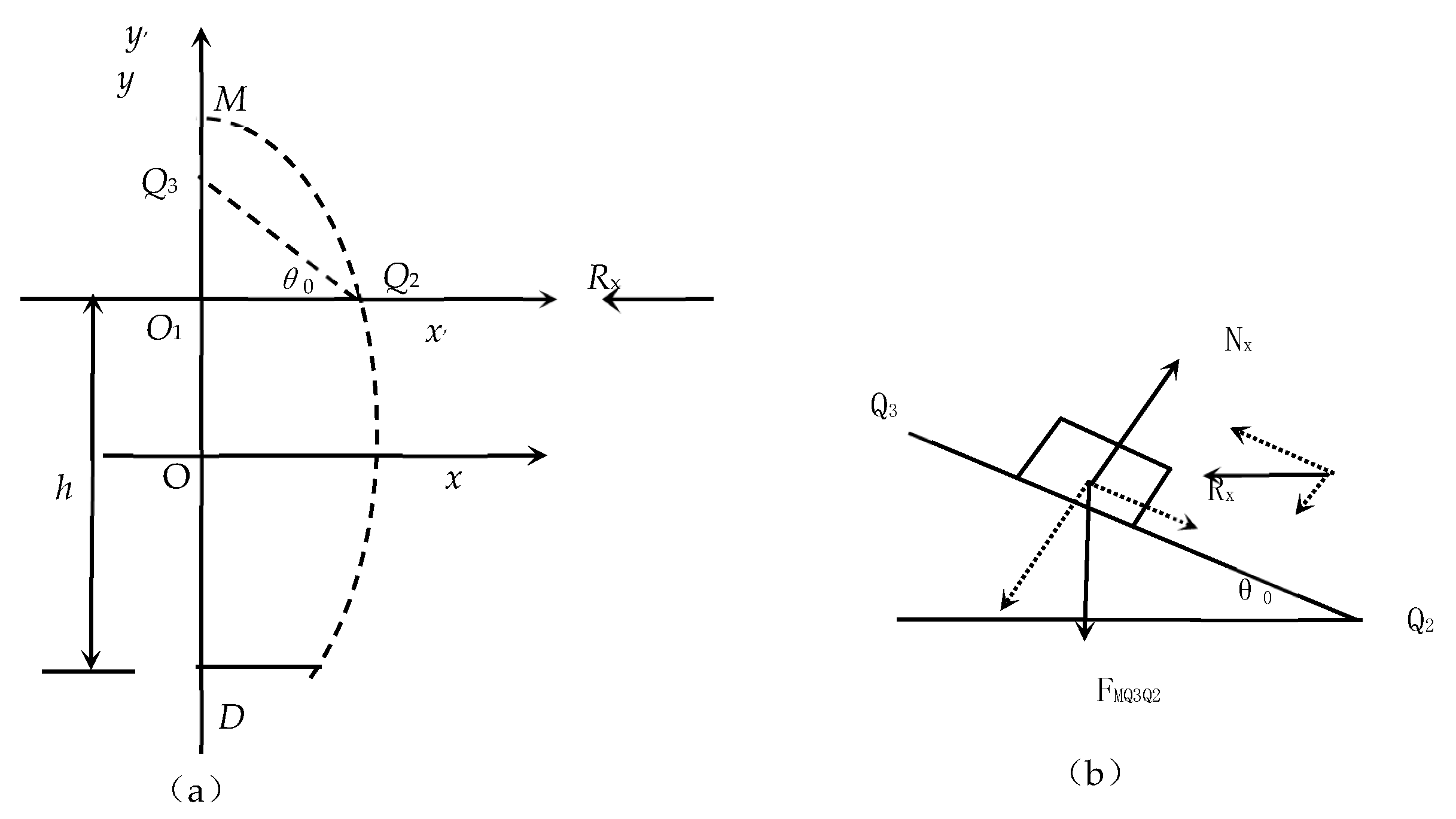
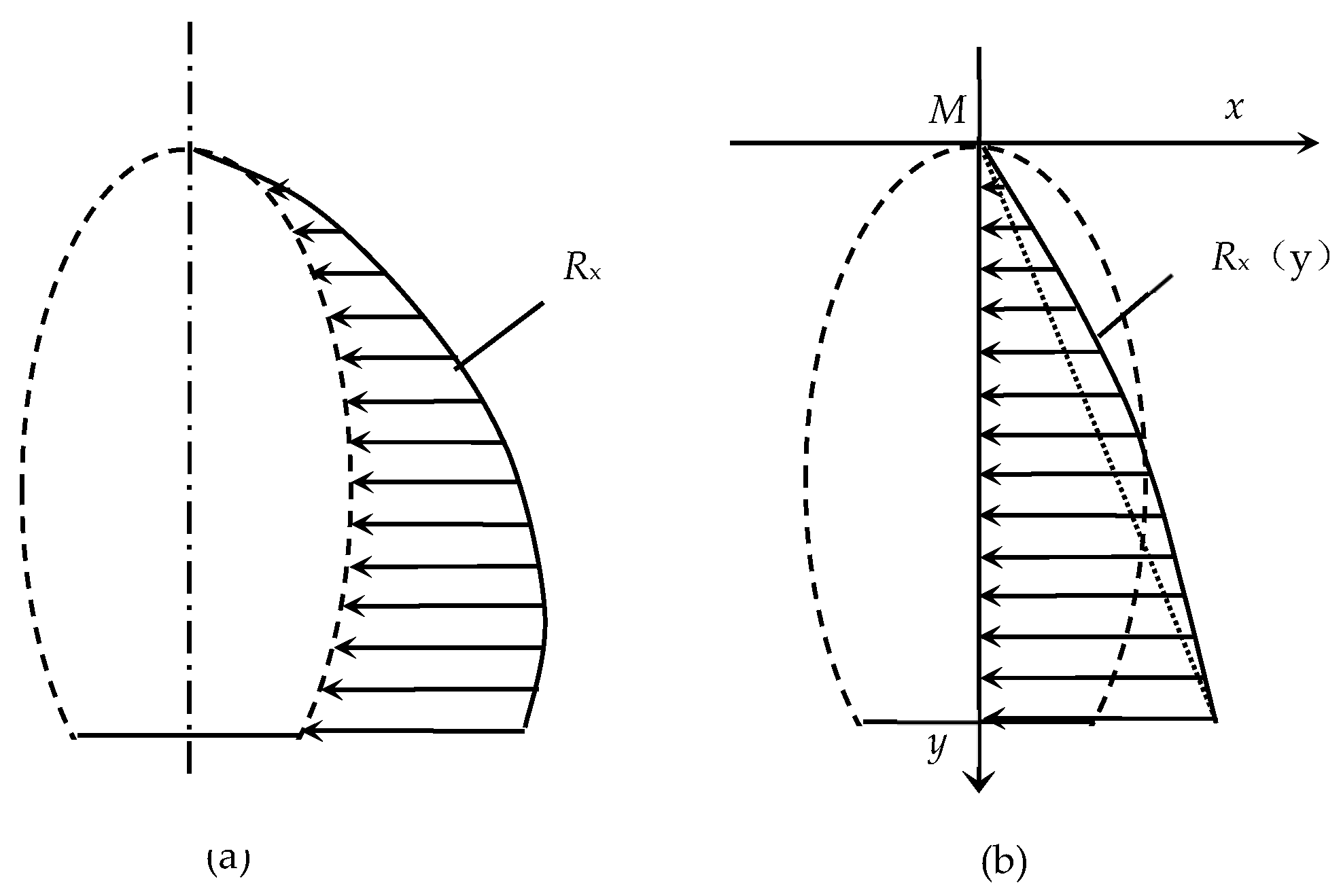
5. Horizontal Forces at the Accumulation Body Boundaries

According to the above-mentioned mechanical characteristics of the accumulation body boundary, the horizontal force on both sides of the accumulation body near the slope only plays a limiting role. Thus, we discuss cases of whether the collapsed space is filled or not.

5.1. Collapse Space Is Fully Filled

When the accumulation body fills the whole collapse space (as shown in Figure 3b), we only take the right half for boundary horizontal force analysis (as shown in Figure 4a), according to the symmetry.
Assuming Q2 is a random point on the edge of the accumulation body, if the distance between point Q2 and the tunnel floor is h, then the ordinate yQ2 of point Q2 can be determined as follows:
y Q 2 = h O D = h H + 2 a 0 a 1 + a 1 2 λ 2 H 2 2 H λ 2
Therefore, according to the elliptic Equation (3), the abscissa xQ2 of point Q2 can be obtained as:
x Q 2 = a b b 2 y 01 2 = a b b 2 h H + 2 a 0 a 1 + a 1 2 λ 2 H 2 2 H λ 2 2
After moving the origin O of the original coordinate upward to point O1, the equation of the original ellipse in the new coordinate system is:
x 2 a 2 + y + y Q 2 2 b 2 = 1
This gives:
y = b a a 2 x 2 y Q 2
By combining with the natural accumulation angle of the accumulation body (θ0), the linear equation of the slip trace (Q3Q2) of the shaded part MQ3Q2 in the new coordinate system is calculated as follows:
f ( x ) = t g θ 0 x x Q 2
Hence, the weight of the accumulation body part bounded by MQ3Q2 is:
F M Q 3 Q 2 = γ 0 x Q 2 b a a 2 x 2 y Q 2 t g θ 0 x x Q 2 d x
where γ is the unit weight of the accumulation body.
Integrating Equation (28) gives:
F M Q 3 Q 2 = γ b 2 a x Q 2 a 2 x Q 1 2 + a b 2 arcsin x Q 2 a y Q 2 x Q 2 t g θ 0 2 x Q 2 2
The force analysis of the shaded part in Figure 4a sliding along Q3Q2 can be simplified as Figure 4b. The resistance Rx is passively generated due to the sliding movement along Q3Q2, and the natural accumulation angle θ0 is displayed after the movement, so the friction between the block in Figure 4b and the inclined plane Q3Q2 is zero, indicating that
R x cos θ 0 = F M Q 3 Q 2 sin θ 0
or
R x = F M Q 3 Q 2 t g θ 0
Therefore, when the accumulation body fills the whole space, at point Q2 on the elliptical trace line, where the distance to the tunnel floor is h, the lateral force Rx at the boundary can be obtained through a combination of Equations (24), (25), (29), and (30).
Through the above analysis, the horizontal force distribution at the boundary of the accumulation body can be obtained, as shown in Figure 5a. In the rectangular coordinate system with M as the origin, the distribution is shown in Figure 5b.

5.2. Collapse Space Is Not Fully Filled

When the accumulation body does not fill the entire collapse space (as shown in Figure 3c), we also only take the right half to analyze the horizontal force at the boundary (as shown in Figure 6a) due to the symmetry.
Q4 is a random point on the edge of the accumulation body, whose distance to the bottom of the mining tunnel is h, combining Equation (22). The burial depth of Q4 in the accumulation body, represented using h2–4, can be calculated using Equation (22), as seen below.
h 2 4 = H b m . Q 1 Q 2 h
Thus, the ordinate of Q4, represented using yQ4, is determined as:
y Q 4 = h O D = h H 2 a 0 a 1 + a 1 2 λ 2 H 2 2 H λ 2
Then, through the elliptic equation, the abscissa of Q4, represented using xQ4, can be obtained as:
x Q 4 = a b b 2 y Q 4 2
The linear equation of the straight line Q3Q2 is:
y Q 3 Q 2 = t g θ 0 x + x Q 2 t g θ 0 + y Q 2
The linear equation of the straight line Q4Q5 is:
y Q 5 Q 4 = t g θ 0 x + x Q 4 t g θ 0 + y Q 4
The elliptic arc equation of Q2Q4 is:
y Q 2 Q 4 = b a a 2 x 2
Thus, the weight of the region bounded by Q3Q2Q4Q5, represented using FQ3Q2Q4Q5, is as follows:
F Q 3 Q 2 Q 4 Q 5 = 0 x Q 2 γ y Q 3 Q 2 y Q 5 Q 4 d x + x Q 2 x Q 4 γ y Q 2 Q 4 y Q 5 Q 4 d x
Integrating Equation (34) gives:
F Q 3 Q 2 Q 4 Q 5 = γ x Q 2 x Q 2 x Q 4 t g θ 0 + y Q 2 y Q 4   + γ b 2 a x Q 4 a 2 x Q 4 2 + a 2 arcsin x Q 4 a x Q 2 a 2 x Q 2 2 + a 2 arcsin x Q 2 a   + γ t g θ 0 2 x Q 4 2 x Q 2 2 x Q 4 t g θ 0 x Q 4 x Q 2 y Q 4 x Q 4 x Q 2
Similarly, the force analysis of the accumulation body Q3Q2Q4Q5 sliding along Q4Q5 in Figure 6a can be simplified as Figure 6b, which gives the following force balance:
R x cos θ 0 = F Q 3 Q 2 Q 4 Q 5 sin θ 0
or
R x = F Q 3 Q 2 Q 4 Q 5 t g θ 0
Based on the above, when the accumulation body cannot fill the entire collapse space, the horizontal force distribution at the boundary is shown in Figure 7a. When it is converted to a rectangular coordinate system with the boundary point Q2 as the origin, the horizontal force distribution at the corresponding boundary position is shown in Figure 7b.

6. Conclusions

The main findings of the work are summarized as follows:
(1)
The accumulation process of the accumulation body in the fault fracture zone is a self-organized mosaic process, and the accumulation process only suffers passive resistance due to the slope slip effect. At the same time, the overall instability outline of the fault fracture zone is elliptical, and the overlying load on the rescue channel to be excavated in the accumulation body is limited.
(2)
The relationship between the maximum lateral instability width and the maximum collapse height of the broken zone of a mining tunnel’s surrounding rock and the height and width of the original tunnel, the lateral stress coefficient, and the internal friction angle of the fragment filling is obtained. The collapse height is also related to the natural accumulation angle of the accumulation body when the collapse space is not filled.
(3)
It is concluded that under the two conditions of whether the collapse space is filled or not, the lateral force at the boundary of the accumulation body depends on the distance to the floor of the mining tunnel, the volume weight of the accumulation body, the natural accumulation angle of the accumulation body, the size of the tunnel, the lateral stress coefficient in the cross-section direction of the tunnel, and the internal friction angle of the fragment filling body in the fracture zone. Its distribution is in a curve relationship with the burial depth in the accumulation body.
The findings are of important reference value for studies, especially theoretical and numerical simulation studies on the excavation of emergency rescue channels and the stability control of surrounding rock in the accumulation body. There are still limitations to the work; for example, the surrounding rock of the mining tunnel contains a lot of fracture networks and different geological conditions, which have a great impact on the boundary force distribution. The next step needs to be an in-depth study.

Author Contributions

Conceptualization, G.Z. and M.L.; methodology, T.Q.; software, L.W.; validation, Y.D. and Z.L.; formal analysis, Y.D.; investigation, L.W.; resources, T.Q.; data curation, G.Z.; writing—original draft preparation, G.Z.; writing—review and editing, M.L.; visualization, Y.D.; supervision, Z.L.; project administration, T.Q.; funding acquisition, L.W. All authors have read and agreed to the published version of the manuscript.

Funding

This research was funded by the National Natural Science Foundation of China (51374097).

Institutional Review Board Statement

Not applicable.

Informed Consent Statement

Not applicable.

Data Availability Statement

Not applicable.

Conflicts of Interest

The authors declare no conflict of interest.

References

  1. Yi, E. Prevention of rock burst by protective seam mining in high-depth strata: A case study. Vibroeng. Procedia 2018, 19, 110–115. [Google Scholar] [CrossRef] [Green Version]
  2. Yonts, B. Analysis of Underground Coal Mine Structures Subjected to Dynamic Events; University of Kentucky: Lexington KY, USA, 2018. [Google Scholar]
  3. Zhang, G.-H.; Li, W.-C.; Chen, G.; Hao, C.-B.; Zhang, D.-P. Simulation study on rescue channel position and section shape selection for accumulation body of collapse-collapse. J. Heilongjiang Univ. Sci. Technol. 2017, 27, 1–7. [Google Scholar]
  4. Chen, G.; Teng, P.; Duan, H.; Zhang, G.; Li, T. Characteristics of Collapse Accumulation Body in Roadway and Numerical Simulation of Rescue Channel Excavation. Geotech. Geol. Eng. 2022, 40, 1121–1133. [Google Scholar] [CrossRef]
  5. Li, Z.; Zhang, H.; Jiang, Z.; Feng, G.-R.; Cui, J.-Q.; Ma, J.-K. Research on failure criteria and collapse height of roadway roof strata based on energy accumulation and dissipation characteristics. Energy Sci. Eng. 2021, 9, 2461–2473. [Google Scholar] [CrossRef]
  6. Song, D.; He, X.; Wang, E.; Li, Z.; Wei, M.; Mu, H. A dynamic ejection coal burst model for coalmine roadway collapse. Int. J. Min. Sci. Technol. 2019, 29, 557–564. [Google Scholar] [CrossRef]
  7. Feng, X.; Ding, Z.; Hu, Q.; Zhao, X.; Ali, M.; Banquando, J.T. Orthogonal numerical analysis of deformation and failure characteristics of deep roadway in coal mines: A case study. Mineral 2022, 12, 185. [Google Scholar] [CrossRef]
  8. Protasov, M.I.; Gadylshin, K.G.; Tcheverda, V.A.; Pravduhin, A.P. 3D diffraction imaging of fault and fracture zones via image spectral decomposition of partial images. Geophys. Prospect. 2019, 67, 1256–1270. [Google Scholar] [CrossRef]
  9. Wang, K.; Wang, L.; Ren, B. Failure mechanism analysis and support technology for roadway tunnel in fault fracture zone: A case study. Energies 2021, 14, 3767. [Google Scholar] [CrossRef]
  10. Ding, Z.; Feng, X.; Wang, E.; Wei, Q.; Zhao, Q.; Hu, Q. Acoustic emission response and evolution of precracked coal in the meta-instability stage under graded loading. Eng. Geol. 2022, 312, 106930. [Google Scholar] [CrossRef]
  11. Zheng, C.; Zheng, J.; Peng, X.; Zhou, L. Study on Failure Characteristics and Rock Burst Mechanism of Roadway Roof under Cyclic Dynamic Load. Shock Vib. 2021, 2021, 7074350. [Google Scholar] [CrossRef]
  12. Zhang, J.; Wang, M.; Xi, C. Tunnel Collapse Mechanism and Its Control Strategy in Fault Fracture Zone. Shock Vib. 2021, 2021, 9988676. [Google Scholar] [CrossRef]
  13. McKeighan, C. Analyzing deformation within a normal fault transfer zone using SFM 3D modeling. Proc. Keck Geol. Consort. 2019, 32. [Google Scholar] [CrossRef]
  14. Wu, T.; Chuanbo, Z.; Nan, J.; Yuqing, X.; Zhu, B. Study on the mechanical cumulative damage model of slope fault fracture zone under the cumulative effect of blasting vibration. Period. Polytech. Civ. Eng. 2020, 64, 845–858. [Google Scholar] [CrossRef]
  15. Takahashi, M.; Van den Ende, M.P.A.; Niemeijer, A.R.; Spiers, C.J. Shear localization in a mature mylonitic rock analog during fast slip. Geochem. Geophys. Geosystems 2017, 18, 513–530. [Google Scholar] [CrossRef]
  16. Feng, X.; Ding, Z.; Ju, Y.; Zhang, Q.; Ali, M. “Double Peak” of Dynamic Strengths and Acoustic Emission Responses of Coal Masses Under Dynamic Loading. Nat. Resour. Res. 2022, 31, 1705–1720. [Google Scholar] [CrossRef]
  17. Bahaaddini, M. Effect of boundary condition on the shear behaviour of rock joints in the direct shear test. Rock Mech. Rock Eng. 2017, 50, 1141–1155. [Google Scholar] [CrossRef]
  18. Hao, C.-B.; Yu, H.-J.; Zhang, G.H.; Pu, W.L. Caving forms of roadway deposit underground geological fault fracture zone. J. Heilongjiang Univ. Sci. Technol. 2016, 26, 251–255. [Google Scholar]
  19. Saadat, M.; Taheri, A. Effect of contributing parameters on the behaviour of a bolted rock joint subjected to combined pull-and-shear loading: A DEM approach. Rock Mech. Rock Eng. 2020, 53, 383–409. [Google Scholar] [CrossRef]
  20. Saadat, M.; Taheri, A. A cohesive grain based model to simulate shear behaviour of rock joints with asperity damage in polycrystalline rock. Comput. Geotech. 2020, 117, 103254. [Google Scholar] [CrossRef]
  21. Fan, L.; Liu, S. A conceptual model to characterize and model compaction behavior and permeability evolution of broken rock mass in coal mine gobs. Int. J. Coal Geol. 2017, 172, 60–70. [Google Scholar] [CrossRef]
  22. Zhang, C.; Li, H.; Tian, X. The research and application of support technology in high stress broken surrounding rock roadway. Mine Eng. 2016, 4, 57–63. [Google Scholar] [CrossRef]
  23. Wang, P.; Feng, T.; Zhu, Y.; Yu, W. Experimental study on secondary bearing mechanism of weakly cemented broken rock mass. J. Vibroeng. 2019, 21, 2228–2241. [Google Scholar] [CrossRef]
  24. Peng, W.; Zhu, H.; Wang, Q.; Peng, G. Study on safety control of large-section roadway with high stress and broken surrounding rock. Adv. Civ. Eng. 2021, 2021, 6686208. [Google Scholar] [CrossRef]
  25. Watabe, Y.; Sassa, S.; Kaneko, T.; Nakata, Y. Mechanical characteristics of undisturbed coral gravel soils: The intergranular void ratio as a common governing parameter. Soils Found. 2017, 57, 760–775. [Google Scholar] [CrossRef]
  26. Li, B.; Wang, X.; Liu, Z.; Li, T. Study on multi-field catastrophe evolution laws of water inrush from concealed karst cave in roadway excavation: A case of Jiyuan coal mine. Geomat. Nat. Hazards Risk 2021, 12, 222–243. [Google Scholar] [CrossRef]
  27. Zhou, Q.; Gao, Q.; Xu, H.-T. Study on setting angle of bolt forepoling in surrounding fractured rock. J. China Coal Soc. 2009, 34, 1594–1598. [Google Scholar]
  28. Zhang, G.-H.; Yu, H.-J.; Hao, C.-B. Resistance force distribution law of collapse caving accumulation body’s boundary in fault fracture zone. J. Min. Saf. Eng. 2018, 35, 532–537. [Google Scholar]
  29. Zheng, K.-C.; Ding, W.-Q.; Jin, W. Formation law of pressure arch of circular TBM tunnel based on model test and FEM. J. China Coal Soc. 2015, 40, 1270–1275. [Google Scholar]
  30. Zhang, G.-H.; Li, F.-Y. Mine Surrounding Rock Control and Disaster Prevention; China University of Mining and Technology Press: Beijing, China, 2009. [Google Scholar]
  31. Zhang, G.-H. The theory-count about space between bolters support laneway’s side. J. China Coal Soc. 2006, 31, 433–436. [Google Scholar]
  32. YU, Y.-X.; Hong, X.; CHEN, F.-F. Study on load transmission mechanism and limit equilibrium zone of coal wall in extraction opening. J. China Coal Soc. 2012, 37, 1630–1636. [Google Scholar]
Figure 2. A sketch used to calculate the mining tunnel collapse space in the fault fracture zone.
Sustainability 14 16811 g002
Figure 4. Sketches used to calculate the horizontal boundary forces when collapse space is filled. (a) The right half of the collapse space; (b) The force analysis of sliding along Q3Q2.
Sustainability 14 16811 g004
Figure 5. The distribution of horizontal forces at the accumulation body boundary. (a) Force distribution at the external contour; (b) Force distribution in the rectangular coordinate system with M as the origin.
Sustainability 14 16811 g005
Figure 6. Sketches used to calculate the horizontal boundary forces when collapse space is not fully filled. (a) The right half of the collapse space; (b) The force analysis of sliding along Q5Q4.
Sustainability 14 16811 g006
Figure 7. The distribution map of the horizontal force at the accumulation body boundary. (a) Force distribution at the external contour; (b) Force distribution in the rectangular coordinate system with Q2 as the origin.
Sustainability 14 16811 g007
Publisher’s Note: MDPI stays neutral with regard to jurisdictional claims in published maps and institutional affiliations.

