


Study on Occurrence Mechanism and Prevention Technology of Rock Burst in Narrow Coal Pillar Working Face under Large Mining Depth


Abstract
:1. Introduction
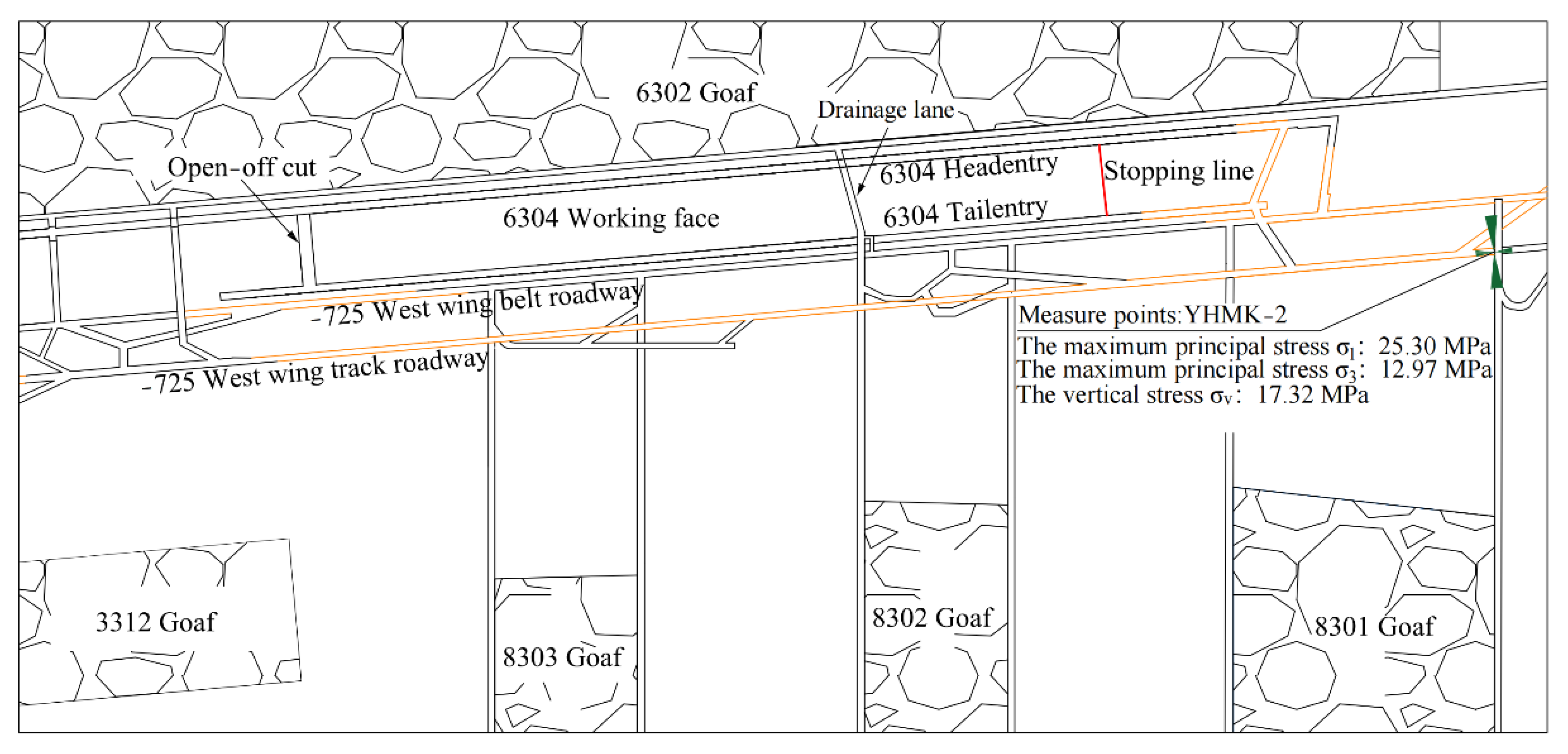
2. Engineering Background
3. Occurrence Mechanism of Roadway Rock Burst in Narrow Coal Pillar Working Face
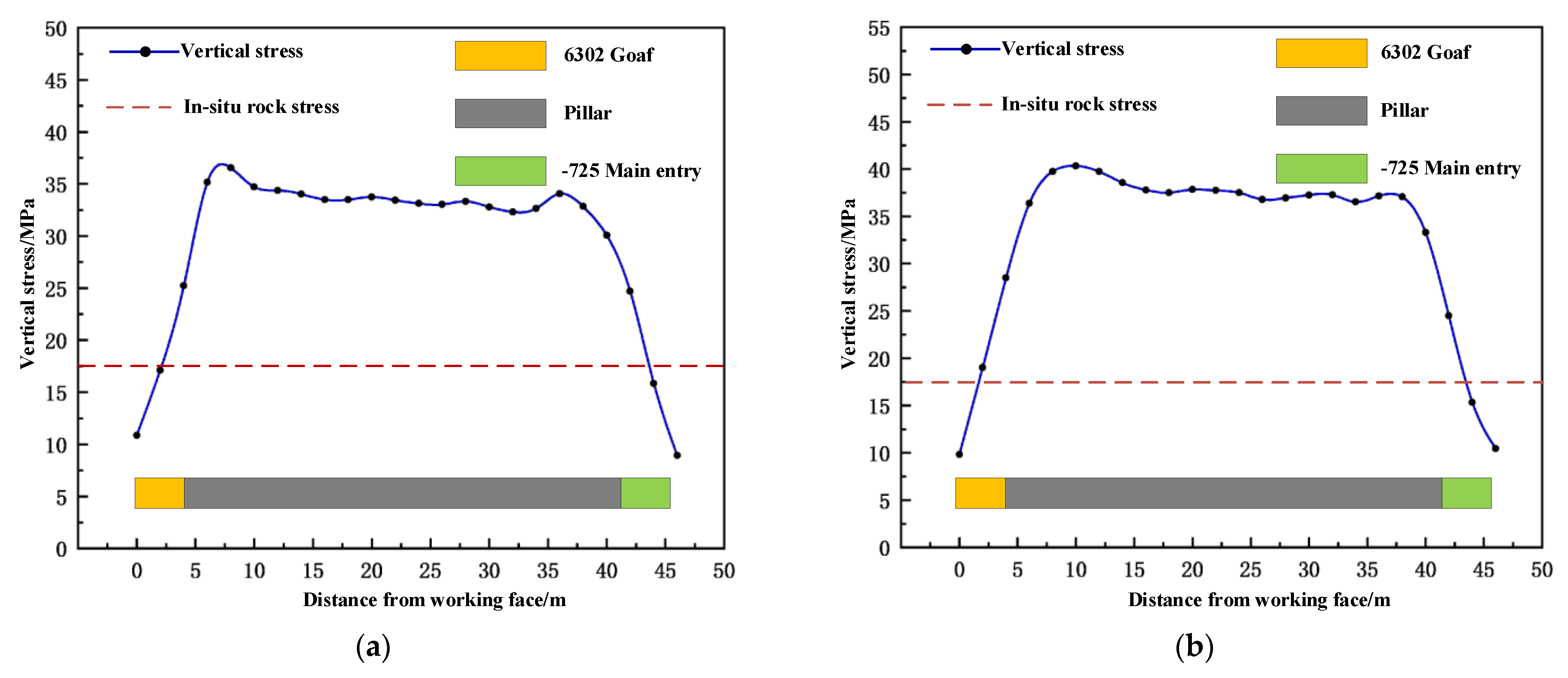
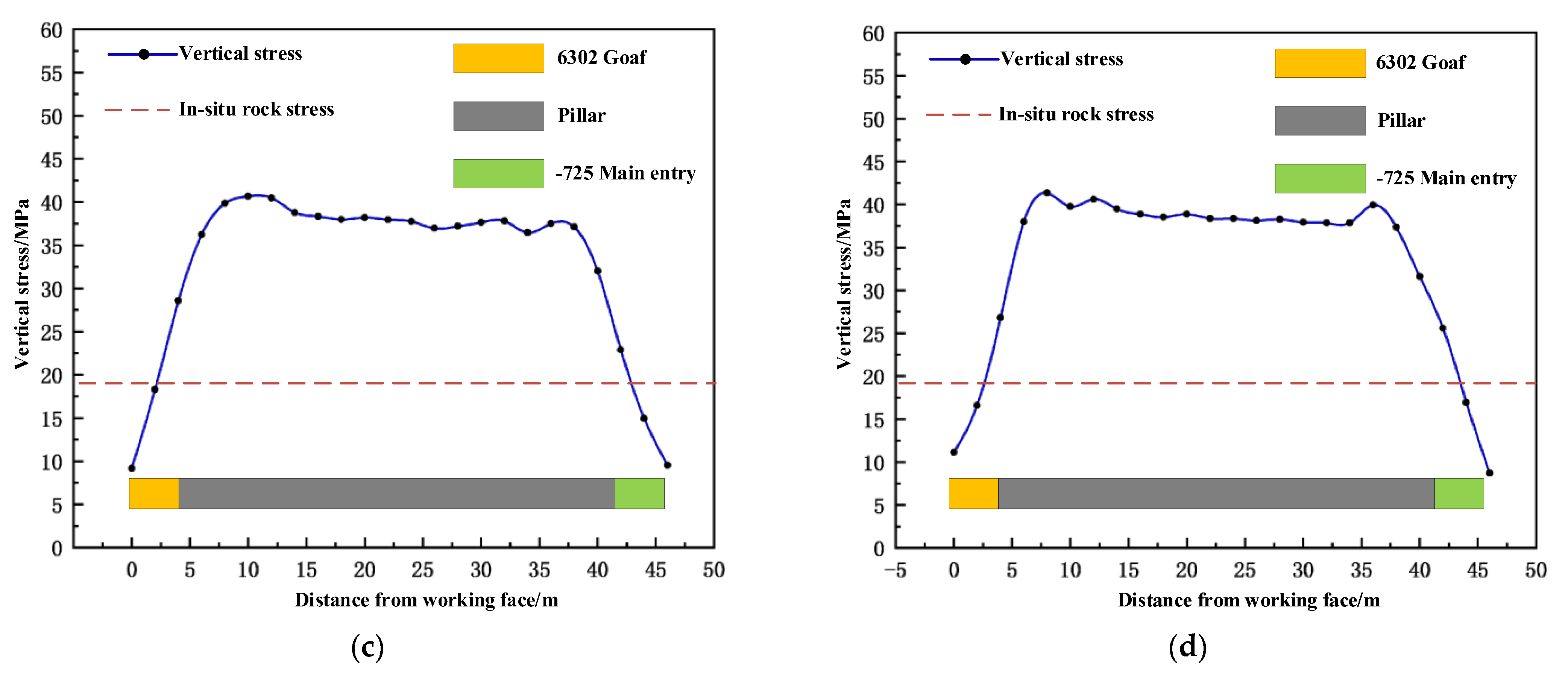
3.1. Energy Accumulation Mechanism of the Coal Seam in Narrow Working Face
3.2. Energy Analysis of Hard Roof Breaking
3.3. Rock Burst inducing Mechanism of Narrow Coal Pillar Working Face
4. Prevention and Control of Rock Burst of Narrow Coal Pillar Working Face
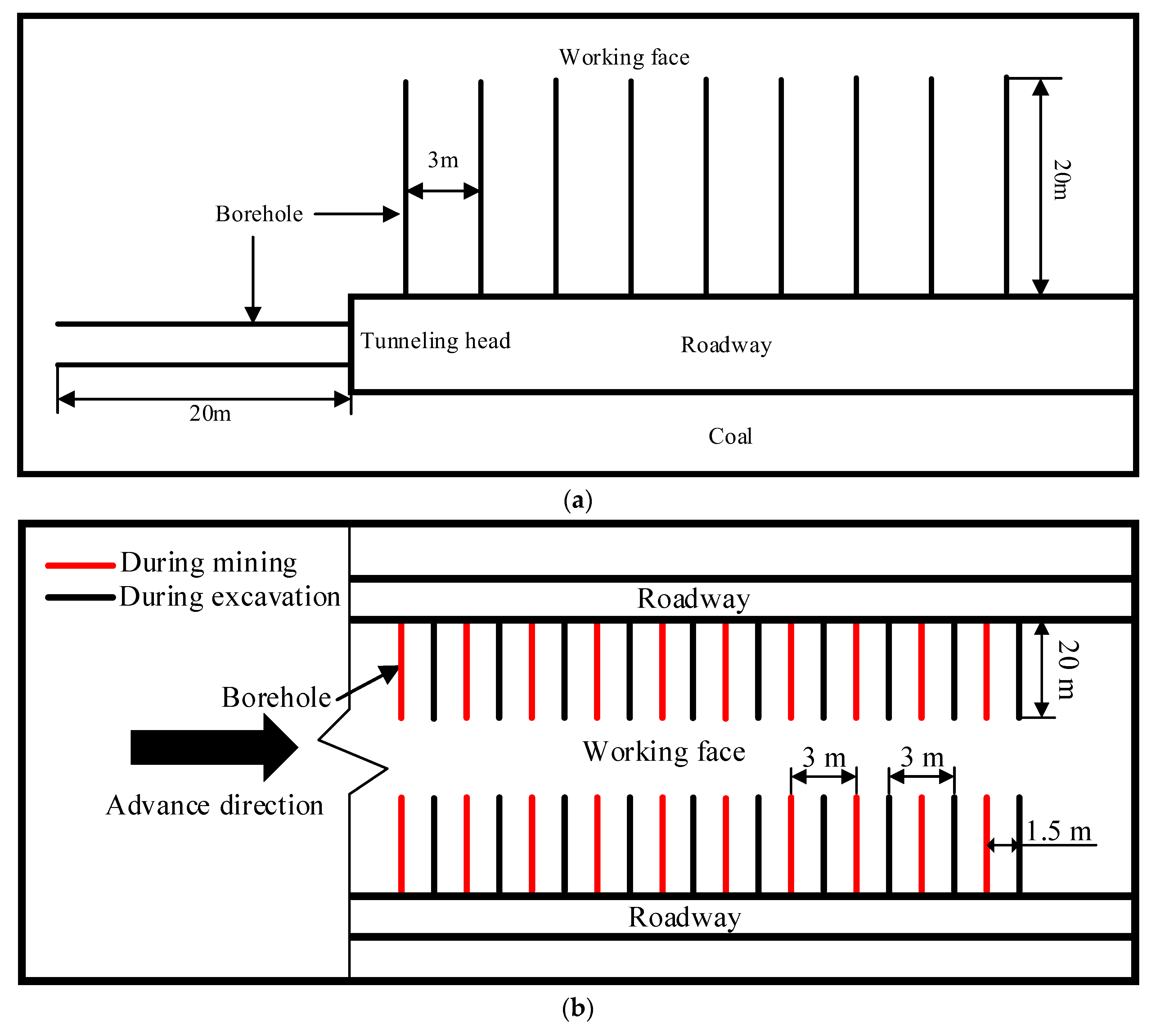
4.1. Prevention and Control Measures against Rock Burst
4.1.1. Coordinated Control of Strong Pressure Relief and Strong Support for Near-Field High-Pressure Coal Mass
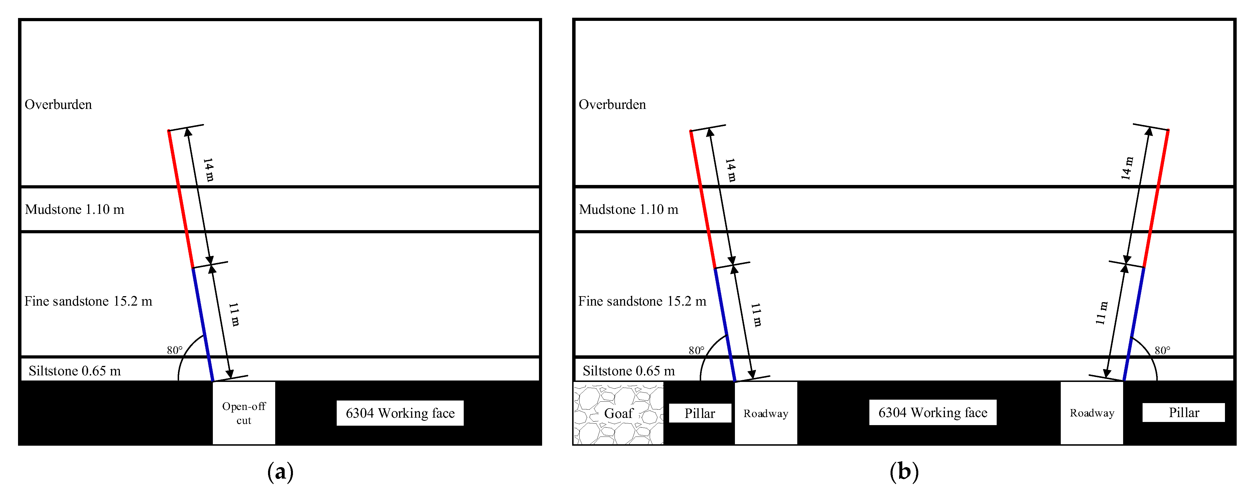
4.1.2. Pressure Relief in the Far-Field High-Level Hard Roof with Advanced Pre-Cracking Roof
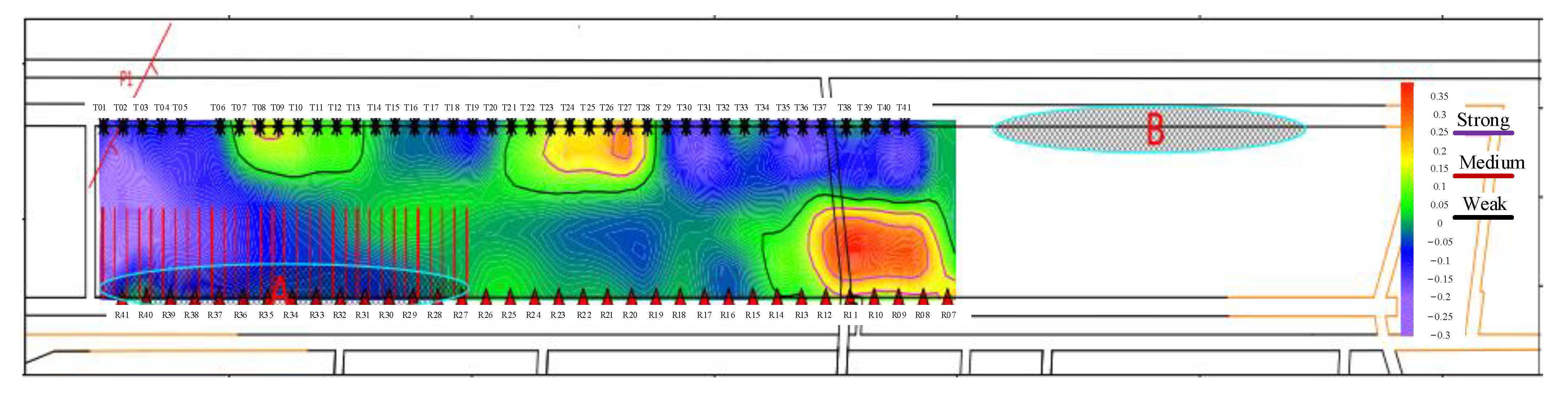
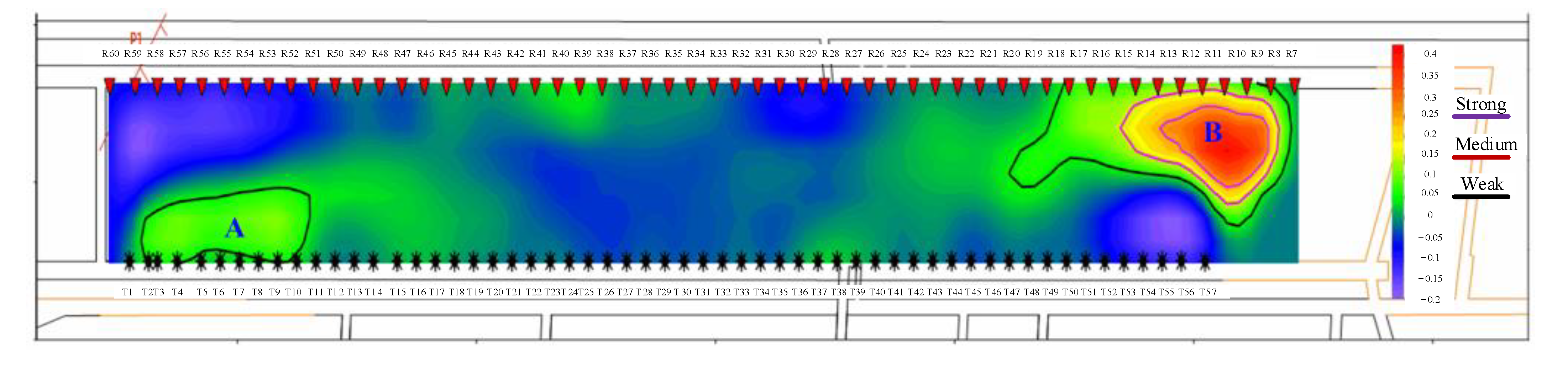
4.2. Evaluation of Pressure Relief Effect
- (1)
- Seismic wave computed tomography-derived
- (2)
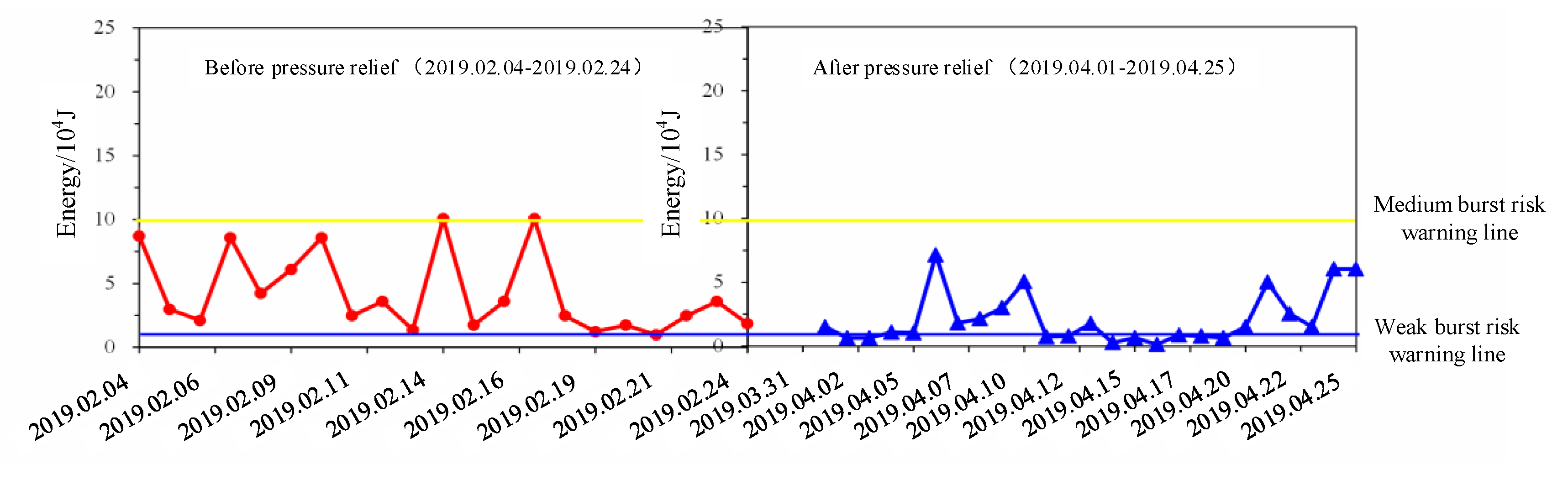
- Microseismic monitoring
5. Conclusions
- (1)
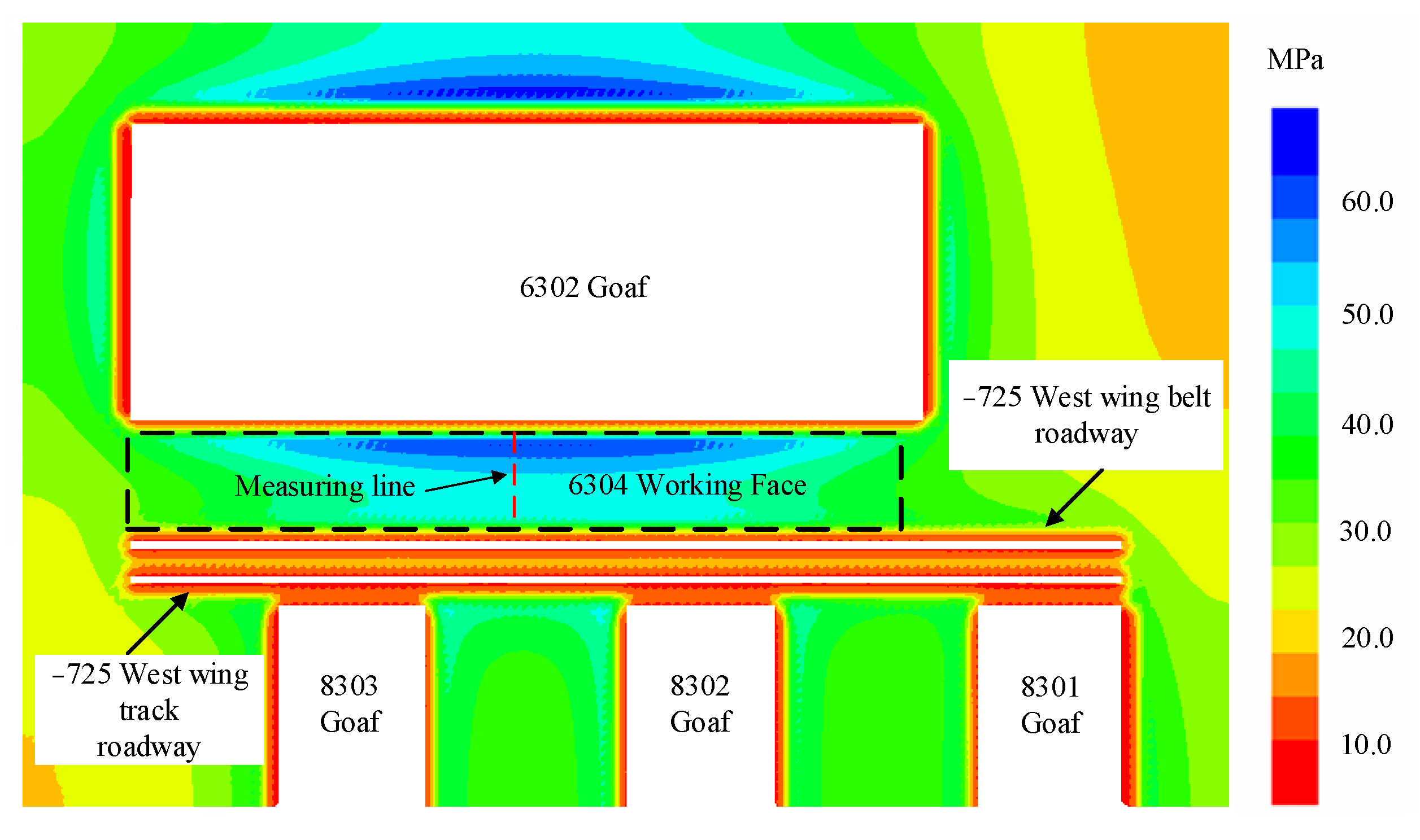
- During roadway excavation, the two roadways of 6304 working face are located within the influenced range of 6302, 8301, 8302, and 8303 goafs, which provides the static load condition for the occurrence of rock burst. Influenced by the peak lateral bearing pressure of adjacent goafs and maximum horizontal principal stress (perpendicular to roadway tunnelling direction), it is difficult to ensure roadway stability.
- (2)
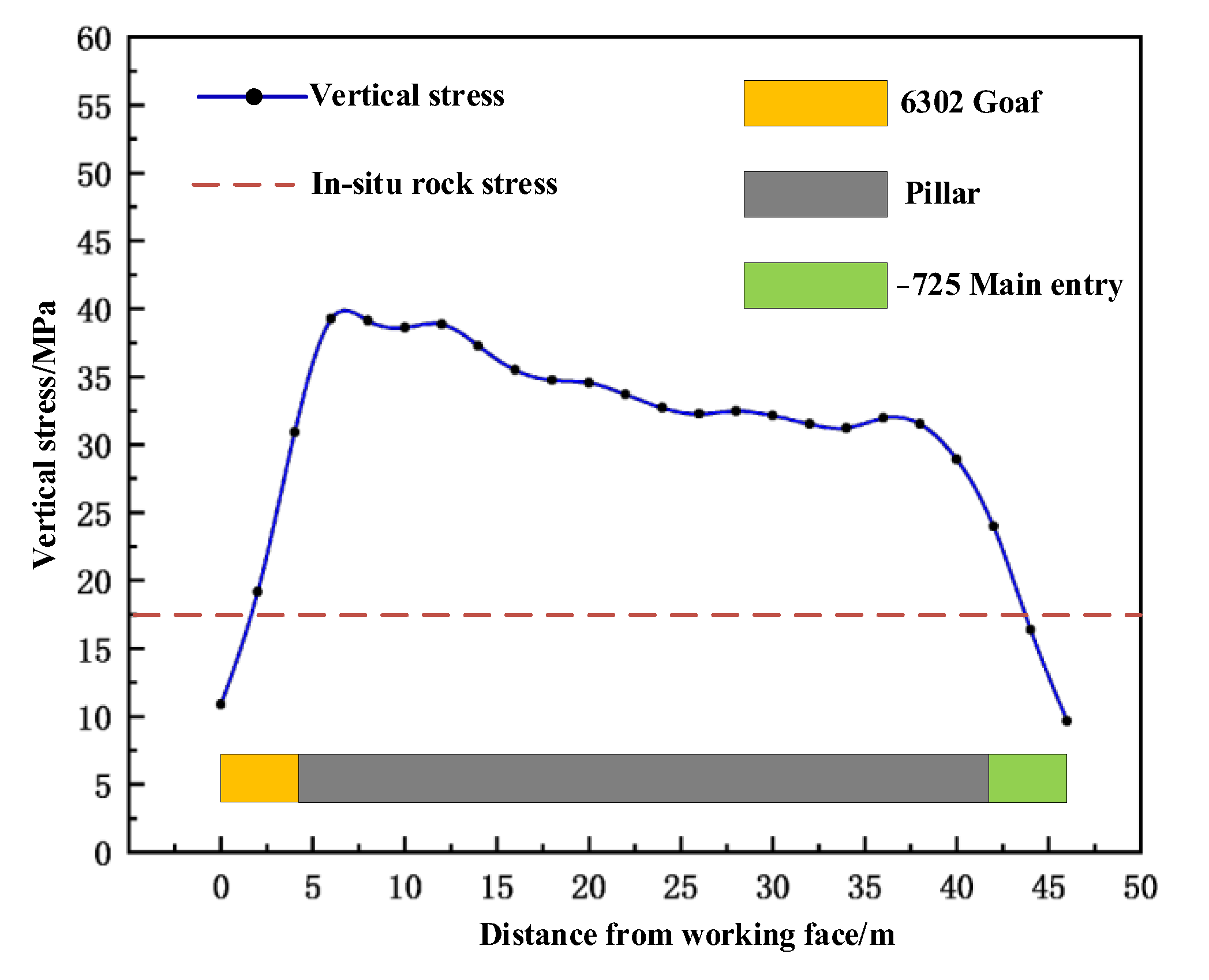
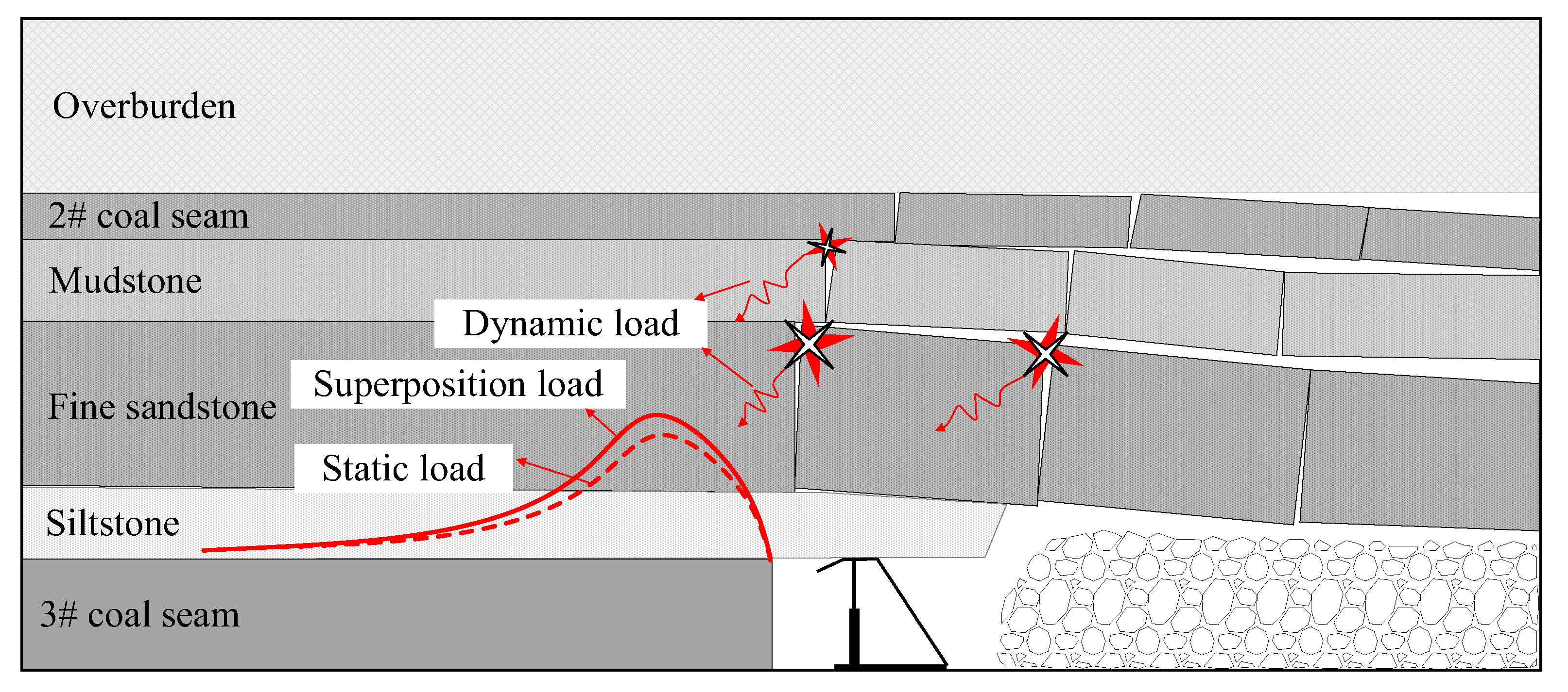
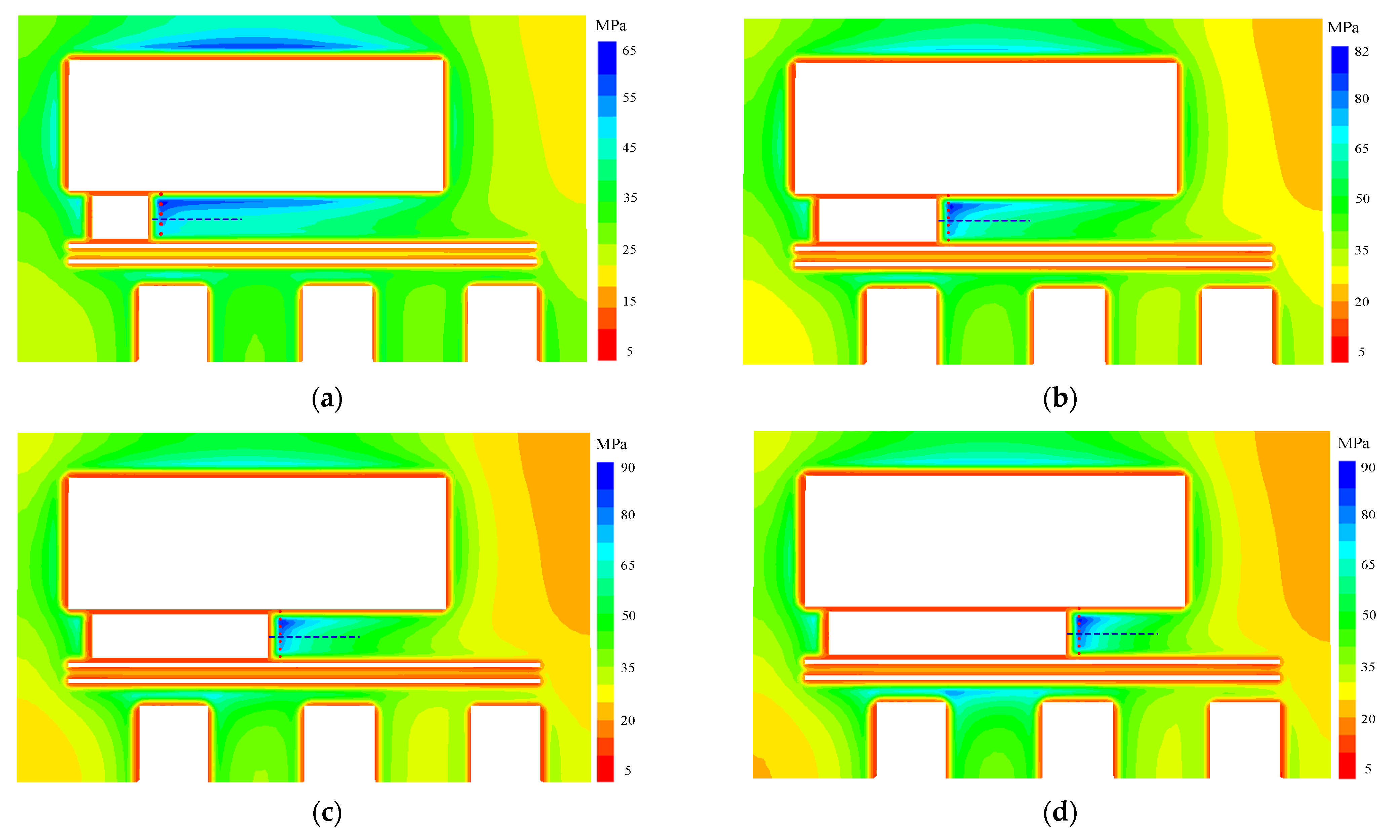
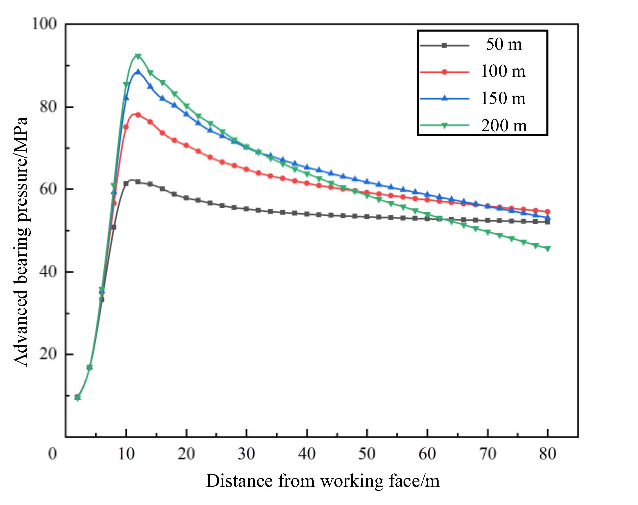
- During mining, the narrow coal pillar working face experiences high static load (crustal stress, lateral bearing pressure of surrounding goafs, and advanced bearing pressure of working face). Meanwhile, movement and breakage of overlying rock stratum on coal seam provide dynamic load conditions (energy releases instantaneously when the overlying rock stratum breaks) for the occurrence of rock burst. Once the hard roof breaks, the energy that is theoretically released will reach 79.9 × 10⁶ J. Under the superposition of “near-field high static load + far-field dynamic load”, the critical destabilization value in narrow coal pillar working face can easily be exceeded, ultimately leading to a rock burst accident.
- (3)
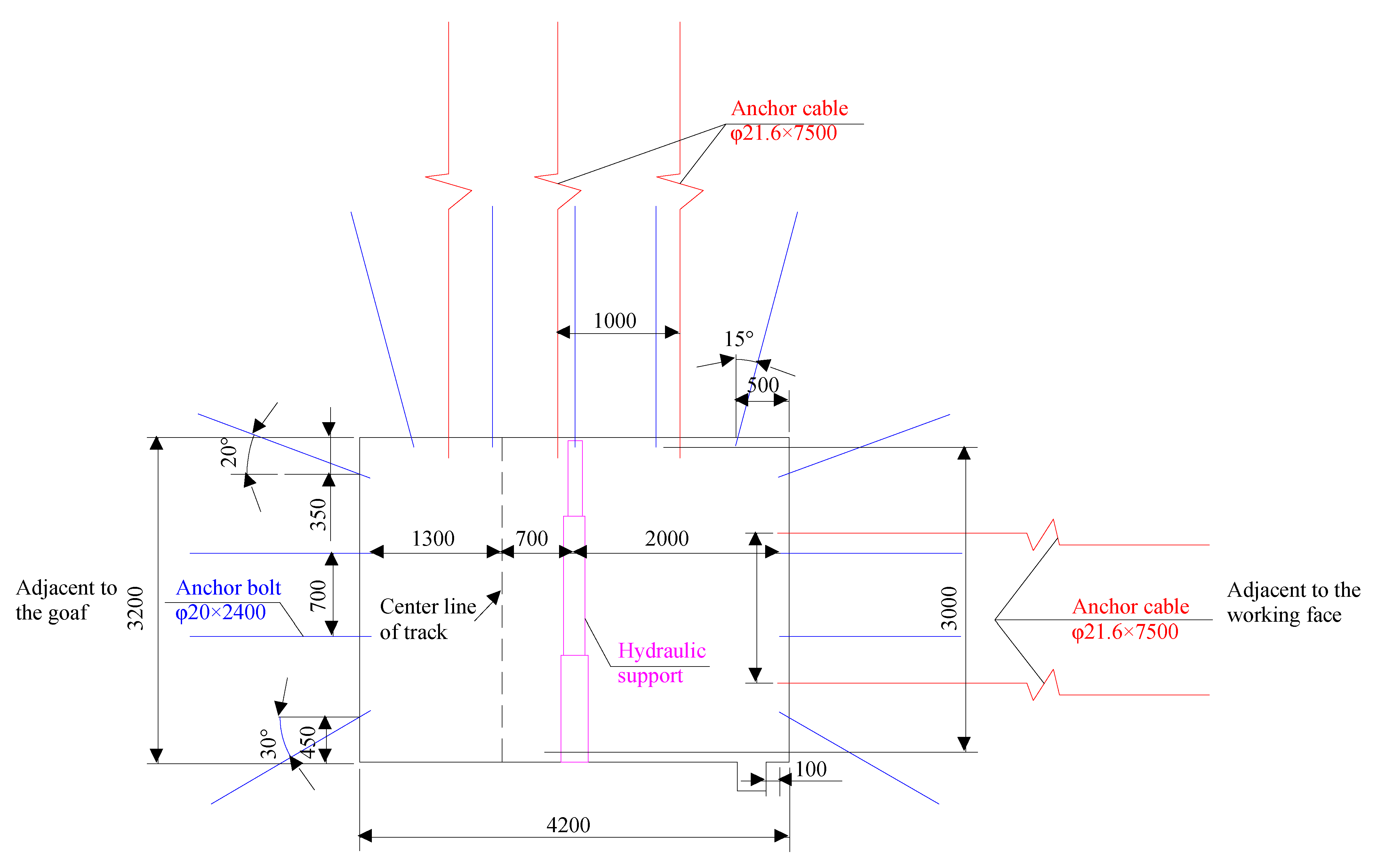
- A coordinated control scheme, which focuses on strong pressure relief and strong support in near-field high-pressure coal mass and pressure relief in far-field high-level hard roof with an advanced pre-cracking roof, is formulated. The field monitoring results show that the overall energy values monitored by the microseismic system are significantly reduced and most of which are below 2.5 × 10⁴ J after pressure relief. It provides a beneficial reference for the prevention and control practice of rock burst at the narrow working face under similar conditions.
Author Contributions
Funding
Institutional Review Board Statement
Informed Consent Statement
Data Availability Statement
Acknowledgments
Conflicts of Interest
References
- Liu, F.; Cao, W.J.; Zhang, J.M.; Cao, G.M.; Guo, L.F. Current technological innovation and development direction of the 14th Five-Year Plan period in China coal industry. J. China Coal Soc. 2021, 46, 1–15. [Google Scholar]
- Wang, G.F.; Reng, S.H.; Pang, Y.H.; Qu, S.J.; Zheng, D.Z. Development achievements of China’s coal industry during the 13th Five-Year Plan period and implementation path of “dual carbon” target. J. China Coal Soc. 2021, 49, 1–10. [Google Scholar]
- Xie, H.P.; Reng, S.H.; Xie, Y.C.; Jiao, X.M. Development opportunities of the coal industry towards the goal of carbon neutrality. J. China Coal Soc. 2021, 46, 2197–2211. [Google Scholar]
- Cao, A.Y.; Chen, F.; Liu, Y.Q.; Dou, L.M.; Wang, C.B.; Yang, X.; Bai, X.Q.; Song, S.K. Response characteristics of rupture mechanism and source arameters of mining tremors in frequent coal burst area. J. China Coal Soc. 2022, 47, 722–733. [Google Scholar]
- Pan, J.F.; Liu, S.H.; Gao, J.M.; Sun, X.K.; Xia, Y.X.; Wang, Q. Prevention theory and technology of rock burst with distinguish dynamic and static load sources in deep mine roadway. J. China Coal Soc. 2020, 45, 1607–1613. [Google Scholar]
- Wang, E.Y.; Feng, J.J.; Zhang, Q.M.; Kong, X.G.; Liu, X.F. Mechanism of rockburst under stress wave in mining spac. J. China Coal Soc. 2020, 45, 100–110. [Google Scholar]
- Dou, L.M.; Lu, C.P.; Mou, Z.L.; Qin, Y.H.; Yao, J.M. Intensity weakening theory for rockburst and its application. J. China Coal Soc. 2005, 30, 690–694. [Google Scholar]
- Zhao, Y.X.; Zhou, J.L.; Liu, W.G. Characteristics of ground pressure and mechanism of coal burst in the gob side roadway at Xinjie deep mining area. J. China Coal Soc. 2020, 45, 1595–1606. [Google Scholar]
- Zhao, T.-B.; Guo, W.-Y.; Tan, Y.-L.; Yin, Y.-C.; Cai, L.-S.; Pan, J.-F. Case Studies of Rock Bursts Under Complicated Geological Conditions During Multi-seam Mining at a Depth of 800 m. Rock Mech. Rock Eng. 2018, 51, 1539–1564. [Google Scholar] [CrossRef]
- Zhou, K.; Dou, L.; Gong, S.; Li, J.; Cao, J. Study of Rock Burst Risk Evolution in Front of Deep Longwall Panel Based on Passive Seismic Velocity Tomography. Geofluids 2020, 2020, 8888413. [Google Scholar] [CrossRef]
- Wang, J.-C.; Jiang, F.-X.; Meng, X.-J.; Wang, X.-Y.; Zhu, S.-T.; Feng, Y. Mechanism of Rock Burst Occurrence in Specially Thick Coal Seam with Rock Parting. Rock Mech. Rock Eng. 2016, 49, 1953–1965. [Google Scholar] [CrossRef]
- Keneti, A.; Sainsbury, B.-A. Review of published rockburst events and their contributing factors. Eng. Geol. 2018, 246, 361–373. [Google Scholar] [CrossRef]
- Yang, Y.; Wei, S.; Li, K. Inverse analysis of dynamic failure characteristics of roadway surrounding rock under rock burst. Energy Sci. Eng. 2021, 9, 2298–2310. [Google Scholar] [CrossRef]
- Xu, L.; Lu, K.; Pan, Y.; Qin, Z. Study on rock burst characteristics of coal mine roadway in China. Energy Sources Part A Recovery Util. Environ. Eff. 2022, 44, 3016–3035. [Google Scholar] [CrossRef]
- Zhao, T.-B.; Guo, W.-Y.; Tan, Y.-L.; Lu, C.-P.; Wang, C.-W. Case histories of rock bursts under complicated geological conditions. Bull. Eng. Geol. Environ. 2018, 77, 1529–1545. [Google Scholar] [CrossRef]
- Zhou, N.; Liu, H.F.; Zhang, J.X.; Yan, H. Study on Rock Burst Event Disaster and Prevention Mechanisms of Hard Roof. Adv. Civ. Eng. 2019, 2019, 6910139. [Google Scholar] [CrossRef]
- Lu, A.; Dou, L.; Bai, J.; Chai, Y.; Zhou, K.; Kan, J.; Cao, J.; Song, S.; Deyuan, F. Mechanism of Hard-Roof Rock Burst Control by the Deep-Hole Blasting: Numerical Study Based on Particle Flow. Shock Vib. 2021, 2021, 9527956. [Google Scholar] [CrossRef]
- Shi, X.; Zhang, X.; Jiang, F.; Wang, H.; Wei, J. Study on Practice of Rockburst Accident Prevention in Multi-Seam Mining Controlled by Large Fault and Hard Roof. Geotech. Geol. Eng. 2020, 38, 6843–6853. [Google Scholar] [CrossRef]
- Guo, W.; Li, Y.; Yin, D.; Zhang, S.; Sun, X. Mechanisms of rock burst in hard and thick upper strata and rock-burst controlling technology. Arab. J. Geosci. 2016, 9, 561. [Google Scholar] [CrossRef]
- Wang, C.; Cao, A.; Zhu, G.; Jing, G.; Li, J.; Chen, T. Mechanism of rock burst induced by fault slip in an island coal panel and hazard assessment using seismic tomography: A case study from Xuzhuang colliery, Xuzhou, China. Geosci. J. 2017, 21, 469–481. [Google Scholar] [CrossRef]
- Khademian, Z.; Ugur, O. Computational framework for simulating rock burst in shear and compression. Int. J. Rock Mech. Min. Sci. 2018, 110, 279–290. [Google Scholar] [CrossRef]
- Lu, C.-P.; Liu, B.; Liu, B.; Liu, Y.; Wang, H.-Y.; Zhang, H. Anatomy of mining-induced fault slip and a triggered rockburst. Bull. Eng. Geol. Environ. 2019, 78, 5147–5160. [Google Scholar] [CrossRef]
- Manouchehrian, A.; Cai, M. Numerical modeling of rockburst near fault zones in deep tunnels. Tunn. Undergr. Space Technol. 2018, 80, 164–180. [Google Scholar] [CrossRef]
- Wang, P.; Jiang, L.-S.; Zheng, P.-Q.; Qin, G.-P.; Zhang, C. Inducing mode analysis of rock burst in fault-affected zone with a hard–thick stratum occurrence. Environ. Earth Sci. 2019, 78, 467. [Google Scholar] [CrossRef]
- Jiang, F.X.; Cheng, G.; Feng, Y.; Wang, C.W.; Xu, Y.Y. Research on coal overall instability of isolated working face with irregular gobs on both sides. Chin. J. Geotech. Eng. 2015, 34 (Suppl. S2), 4164–4170. [Google Scholar]
- Xue, C.C.; Cao, A.Y.; Niu, F.W.; Wang, X.Y.; Shen, Z.P.; Tang, K. Mechanism and prevention of rock burst in deep irregular isolated coal pillar. Chin. J. Geotech. Eng. 2021, 38, 479–486. [Google Scholar]
- Du, T.T.; Ju, W.J.; Chen, J.Q.; Zhang, C.J.; Li, H.P.; Sun, R.D. Mechanism of rock burst in fully mechanized caving faces under residual coal seams with hard roof. Chin. J. Geotech. Eng. 2021, 38, 1144–1151. [Google Scholar]
- Zhu, G.A.; Dou, L.M.; Ding, Z.W.; Xie, J.H. Pre-evaluation for rock burst risks in island longwall panel before mining. Chin. J. Geotech. Eng. 2018, 40, 819–827. [Google Scholar]
- Tan, Y.L.; Guo, W.Y.; Zhao, T.B.; Meng, X.J. Coal rib burst mechanism in deep roadway and “stress relief—Support reinforcement” synergetic control and prevention. J. China Coal Soc. 2020, 45, 66–81. [Google Scholar]
- Cao, A.; Dou, L.; Cai, W.; Gong, S.; Liu, S.; Jing, G. Case study of seismic hazard assessment in underground coal mining using passive tomography. Int. J. Rock Mech. Min. Sci. 2015, 78, 1–9. [Google Scholar] [CrossRef]
- Gao, M.; Zhao, H.; Zhao, Y.; Gao, X.; Wang, X. Investigation on the Vibration Effect of Shock Wave in Rock Burst by In Situ Microseismic Monitoring. Shock Vib. 2018, 2018, 8517806. [Google Scholar] [CrossRef]
- Li, Y.; Zhou, C.; Lian, H. Rockburst Inducement Mechanism and Its Prediction Based on Microseismic Monitoring. Geofluids 2021, 2021, 4028872. [Google Scholar] [CrossRef]
- Ma, T.-H.; Tang, C.-A.; Liu, F.; Zhang, S.-C.; Feng, Z.-Q. Microseismic monitoring, analysis and early warning of rockburst. Geomat. Nat. Hazards Risk 2021, 12, 2956–2983. [Google Scholar] [CrossRef]
- Yu, Q.; Zhao, D.; Xia, Y.; Jin, S.; Zheng, J.; Meng, Q.; Mu, C.; Zhao, J. Multivariate Early Warning Method for Rockburst Monitoring Based on Microseismic Activity Characteristics. Front. Earth Sci. 2022, 10, 837333. [Google Scholar] [CrossRef]


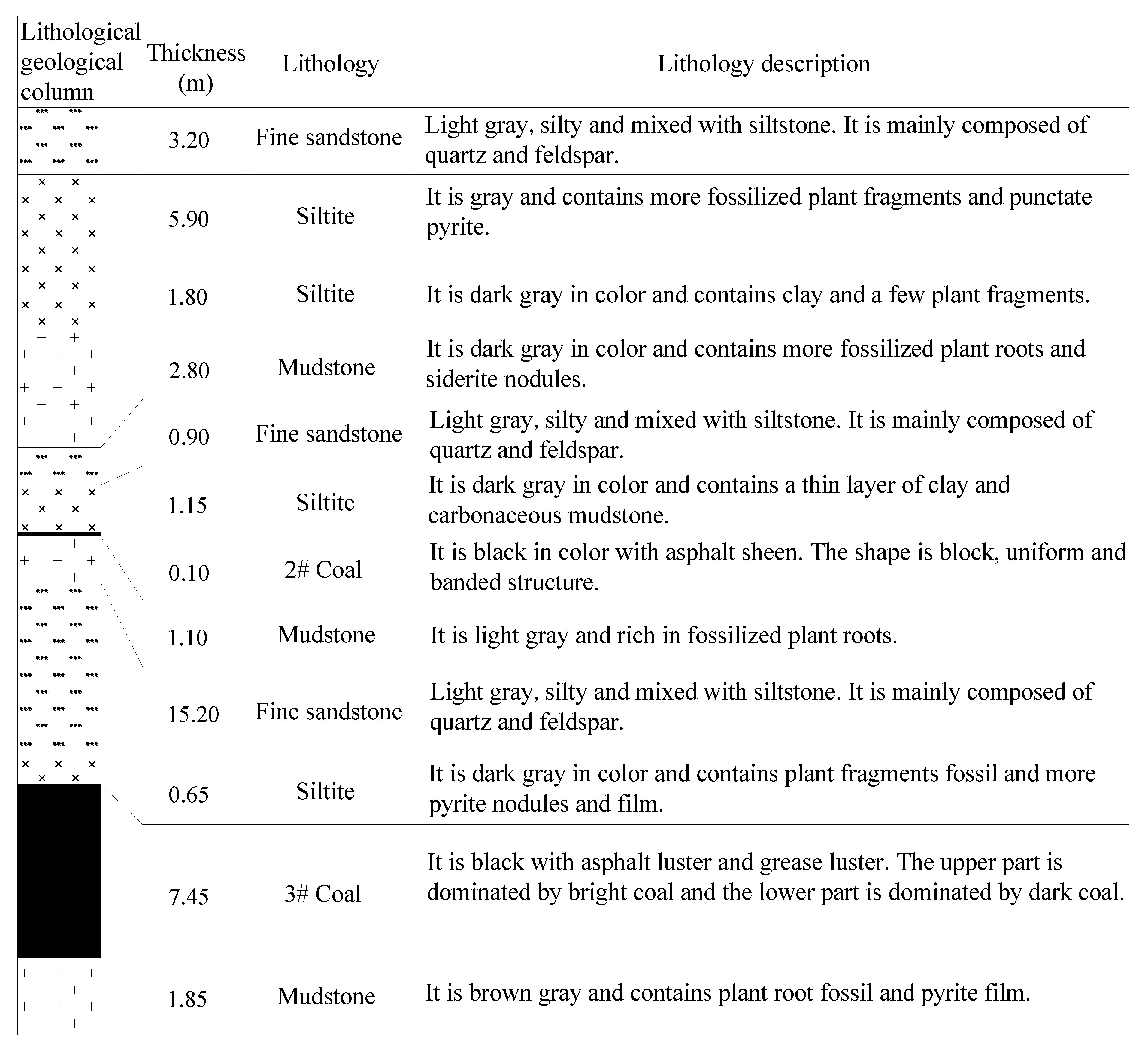
| Rock Number | Lithology | Thickness/m | Rock Number | Lithology | Thickness/m |
|---|---|---|---|---|---|
| 19 | Medium sandstone | 7.00 | 9 | Siltite | 5.90 |
| 18 | Mudstone | 4.57 | 8 | Siltite | 1.80 |
| 17 | Fine sandstone | 7.75 | 7 | Mudstone | 2.80 |
| 16 | Mudstone | 4.97 | 6 | Fine sandstone | 0.90 |
| 15 | Fine sandstone | 1.80 | 5 | Siltite | 1.15 |
| 14 | Mudstone | 6.30 | 4 | 2# Coal | 0.10 |
| 13 | Siltite | 12.38 | 3 | Mudstone | 1.10 |
| 12 | Fine sandstone | 0.80 | 2 | Fine sandstone | 15.20 |
| 11 | Mudstone | 2.30 | 1 | Siltite | 0.65 |
| 10 | Fine sandstone | 3.20 | Coal | 3# Coal seam | 7.45 |
| Monitoring Methods | During Excavation | During Mining | ||
|---|---|---|---|---|
| Warning Number | Warning Area | Warning Number | Warning Area | |
| Drilling cuttings method | 6 | Stop excavation area of tailentry; 21 m ahead of the 10# point of tailentry | 4 | Point 25# of headentry |
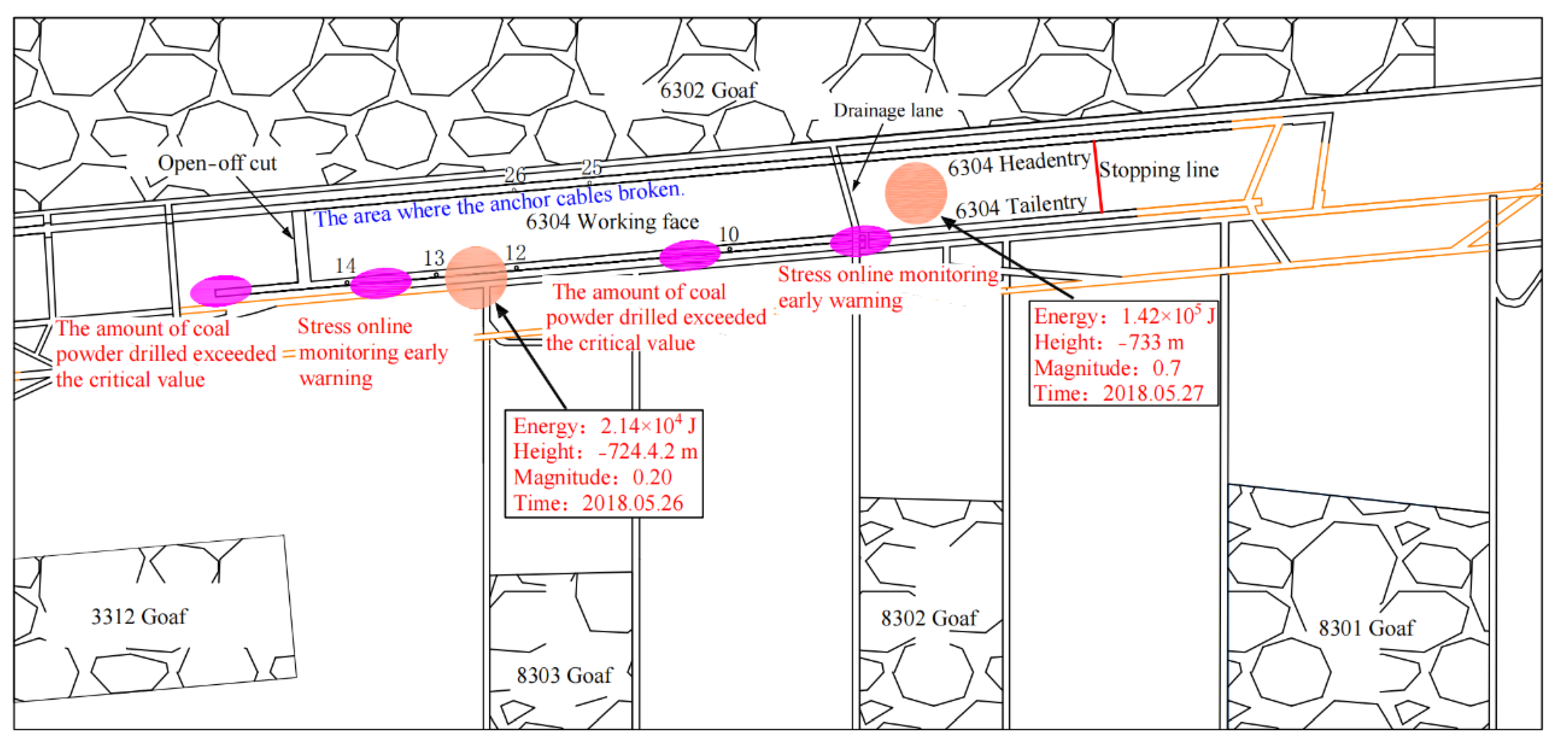
| Microseismic monitoring | 22 | Near the former drainage lane area of 6302; between points 12# and 13# of tailentry | 30 | The 12# point of tailentry; between points 25# and 26# in headentry |
| Stress online monitoring | 7 | 21 m ahead of the 10# point of tailentry | 24 | Area in12# and 14# points of tailentry; near the former drainage lane area of 6302 |
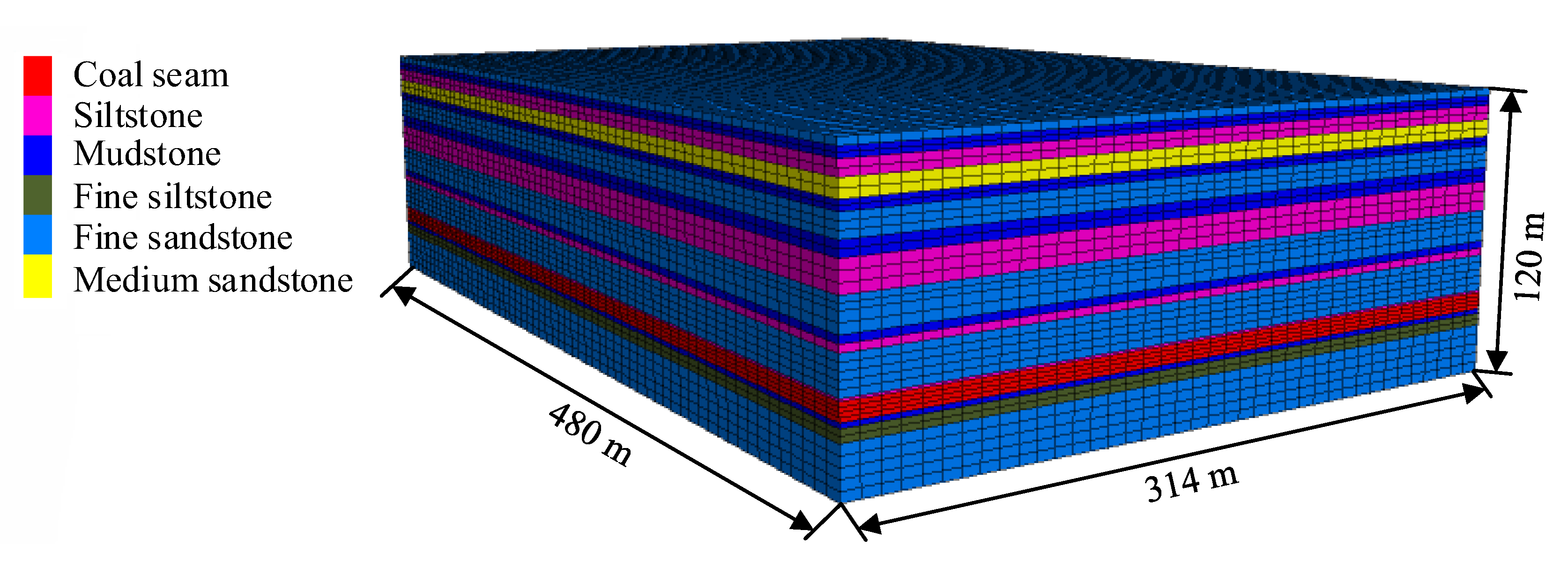
| Lithology | Density/kg/m3 | Bulk Modulus/GPa | Shear Modulus/GPa | Strength of Extension/MPa | Cohesion/MPa | Friction Angle/(°) |
|---|---|---|---|---|---|---|
| Coal seam | 1500 | 6.67 | 1.13 | 1.5 | 2.15 | 27 |
| Fine sandstone | 2600 | 18.44 | 12.15 | 3.5 | 5.8 | 38 |
| Mudstone | 2200 | 10.85 | 3.89 | 2.47 | 3.1 | 30 |
| Siltstone | 2600 | 15.44 | 9.15 | 3.5 | 5.8 | 38 |
| Medium sandstone | 2500 | 18.44 | 12.15 | 3.5 | 5.8 | 38 |
| Fine siltstone | 2500 | 17.96 | 12.36 | 3.8 | 5.93 | 37 |
Publisher’s Note: MDPI stays neutral with regard to jurisdictional claims in published maps and institutional affiliations. |
© 2022 by the authors. Licensee MDPI, Basel, Switzerland. This article is an open access article distributed under the terms and conditions of the Creative Commons Attribution (CC BY) license (https://creativecommons.org/licenses/by/4.0/).
Share and Cite
Gu, S.; Chen, H.; Li, W.; Jiang, B.; Chen, X. Study on Occurrence Mechanism and Prevention Technology of Rock Burst in Narrow Coal Pillar Working Face under Large Mining Depth. Sustainability 2022, 14, 15435. https://doi.org/10.3390/su142215435
Gu S, Chen H, Li W, Jiang B, Chen X. Study on Occurrence Mechanism and Prevention Technology of Rock Burst in Narrow Coal Pillar Working Face under Large Mining Depth. Sustainability. 2022; 14(22):15435. https://doi.org/10.3390/su142215435
Chicago/Turabian StyleGu, Shitan, Huaixu Chen, Wenshuai Li, Bangyou Jiang, and Xiang Chen. 2022. "Study on Occurrence Mechanism and Prevention Technology of Rock Burst in Narrow Coal Pillar Working Face under Large Mining Depth" Sustainability 14, no. 22: 15435. https://doi.org/10.3390/su142215435
APA StyleGu, S., Chen, H., Li, W., Jiang, B., & Chen, X. (2022). Study on Occurrence Mechanism and Prevention Technology of Rock Burst in Narrow Coal Pillar Working Face under Large Mining Depth. Sustainability, 14(22), 15435. https://doi.org/10.3390/su142215435