1. Introduction
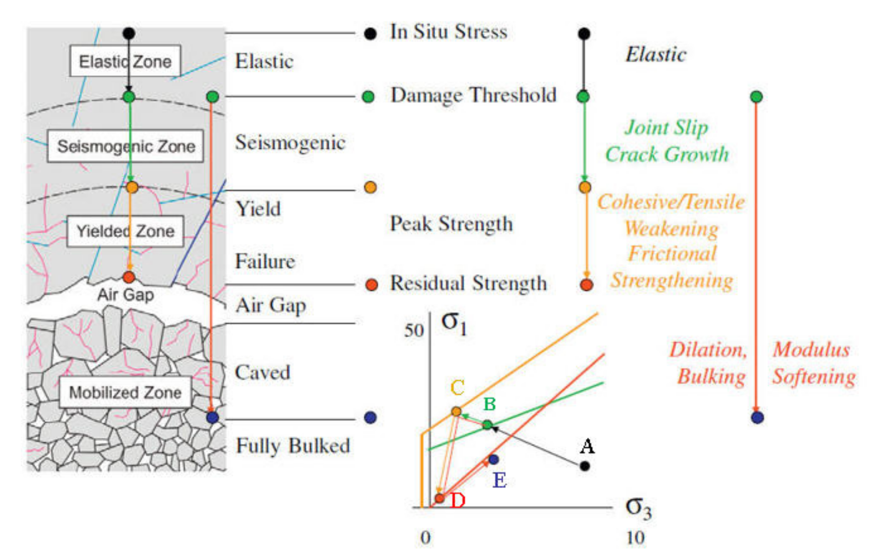
As rock mass is in a complex three-dimensional stress state in the natural environment, the excavation-induced pressure relief will lead to stress redistribution of surrounding rock near the excavation face. During stress adjustment, the secondary stress will cause fracturing damage of surrounding rock and formation of excavation damage zones (EDZ), when it reaches a certain extent [
1]. Bäckblom and Martin [
2] held that the surrounding rock EDZ was formed by the yielding and outward development of rock mass or local rock mass near the excavation face. Read [
3] further explored the causes of EDZ formation in surrounding rock and thought that the tensile stress zone in tunnel surrounding rock may also be one of the causes of surrounding rock excavation damage during rock excavation. In engineering practice, the physical and mechanical properties of surrounding rock EDZ, the detection of EDZ range and the evaluation of damage degree are crucial to the stability of rock engineering structure and the optimization of support parameters [
4,
5,
6,
7].
Since the 1980s, for the purpose of safe storage of radioactive nuclear waste, European countries and the United States have successively established underground rock engineering test sites to study the fracturing damage characteristics of rock mass, including Underground Research Laboratory (URL) of AECL (Atomic Energy of Canada Limited) [
8,
9,
10,
11]; SKB Company and Aspö Hard Rock Laboratory (HRL) of Sweden [
12] and Yucca Mountain test site of the United States [
13]. They have carried out massive on-site tests, monitoring and testing work, and conducted in-depth research on the surrounding rock EDZ. Among them, the research at URL is the most representative. According to a series of laboratory and on-site tests, monitoring and test research on Lac du Bonnet granite at URL, surrounding rock excavation damage is defined as an irrecoverable damage caused by excavation, including damages caused by impacts resulting from excavation methods (such as blasting energy release) and damages caused by crack propagation resulting from stress redistribution and environmental variations (such as temperature and humidity variations).
As the construction of deep rock engineering in China began, research were gradually conducted on surrounding rock excavation damage and some research results have been obtained [
14,
15,
16]. For the purpose of analyzing the formation and evolution mechanism of EDZ, Yan et al. [
17] comparatively analyzed the characteristics and causes of surrounding rock EDZ under two different excavation methods, namely Tunnel Boring Machine (TBM) and drilling and blasting, through an in situ test. Zhu et al. [
18] monitored excavation deformation of underground powerhouse chamber of Dagangshan hydropower station for a long time, and concluded the distribution range and damage deterioration characteristics of underground chamber EDZ. Liu et al. [
19] explored the localization characteristics and degree variations of surrounding rock excavation damage during TBM tunneling through an in situ acoustic emission monitoring test and particle flow code (PFC) numerical simulation.
Excavation damage will result in some permanent variations in the mechanical and hydraulic properties of surrounding rock, including a decrease in rock quality, a reduction of acoustic velocity, an increase in permeability, etc. These variations can be quantitatively tested through technical means such as acoustic detection, micro-seismic or acoustic emission detection, and permeability test. Among them, acoustic detection is widely used on engineering sites for its simple operation, high accuracy, and easy reading of results [
20,
21,
22].
Due to the complexity of surrounding rock excavation damage mechanism, the calculation and theoretical analysis, especially numerical research, on the range of EDZ are not mature enough yet at present. It is difficult to accurately describe the non-linear behavior of rock mass and the excavation damage characteristics of surrounding rock based on the calculation method of continuum mechanics. The PFC is based on the discrete element method. This method starts from the state of contact between particles and its evolution characteristics to describe the basic mechanical properties of rock mass medium, and can reflect surrounding rock excavation damage and its variation characteristics caused by the development of rock micro-fractures [
23,
24,
25]. Therefore, this method is quite suitable for studying the complex macro-meso mechanical behavior of rock mass medium.
In this study, first, the description method of surrounding rock EDZ for the fracturing damage behavior of surrounding rock after excavation of Jinping deeply buried marble tunnels was selected based on the analysis on surrounding rock excavation damage and its evolution characteristics. Second, according to the acoustic detection results of cross-sections in shallow marble tunnel sections under TBM conditions, PFC microscopic parameters of Types II/III marble sections in Jinping tunnels were simulated and calibrated by the PFC2D program. Finally, surrounding rock excavation damage characteristics of the deep tunnel sections of Jinping Types II/III marble tunnels under TBM conditions were simulated with the aid of microscopic parameters of the PFC model of deeply buried marble. This research provides reference for surrounding rock stability analysis and support optimization design in deep tunnel sections.
3. On-Site Test Results of Excavation Damage Depth
Acoustic emission monitoring during excavation is the best method to identify the excavation damage depth of surrounding rock, but it is not systematically conducted on site. Therefore, determination of the excavation damage depth of surrounding rock mainly depends on the on-site acoustic detection results.
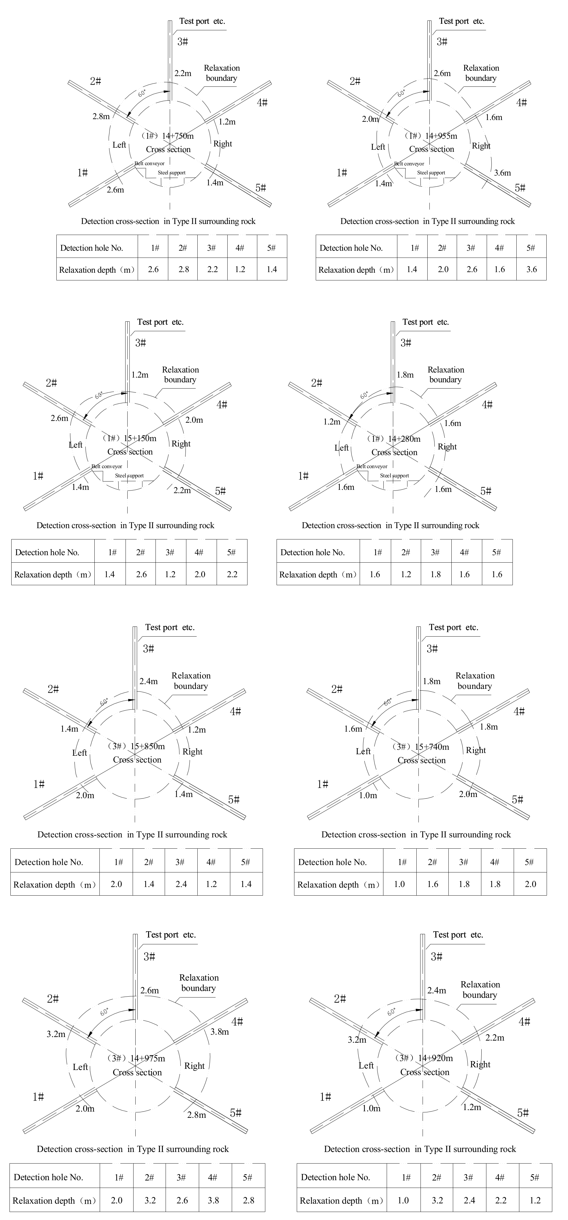
Figure 4 shows the acoustic detection results of partial cross-sections of Jinping 1# and 3# diversion tunnels. The acoustic detection results of the above tunnel cross-sections were summarized and counted (
Table 1).
It can be known from
Figure 4 and
Table 1 that in the statistical results of Type II surrounding rock, the depth of low-wave velocity zone revealed by acoustic detection results generally displays a relatively even distribution on the cross-sections; only the depth near the top arch is relatively large, which is basically consistent with the ground stress state along the Jinping diversion tunnels. The depth of low-wave velocity zone indicated by the acoustic detection results of Type III surrounding rock cross-sections in the top arch zone is generally larger when compared with the detection results of Type II surrounding rock cross-sections.
Since the on-site acoustic detection results do not illustrate the specific geological conditions corresponding to the boreholes, especially for the joint development characteristics in the boreholes, it is difficult to reasonably determine the depth of the EDZ according to the detection results. The reason is that the depth of the low-wave velocity zone of surrounding rock in the tunnel cross-sections is mainly affected by two factors, i.e., the yield degree of surrounding rock and the influence of the structural plane. Relevant research results disclose that the existence of the structural plane can lead to surrounding rock excavation damage in a wider depth range near it, and thus affects the distribution characteristics of low-wave velocity zones on the cross-sections. In the ideal condition without the influence of the structural plane, the shape of the low-wave velocity zone on the tunnel cross-sections is mainly influenced by the initial stress state of the cross-sections, which is the severest in the north arch shoulder and south arch foot of Jinping tunnels. This prediction result is not completely consistent with the acoustic detection results, indicating that the structural plane may exert a significant impact on the test results of low-wave velocity zone of surrounding rock. On Jinping tunnel engineering site, except for the plane, the dominant structural plane in tunnel surrounding rock is NWW and NE joints, in which the NWW joints are developed the most. Among the three groups of structural planes, the angle between the NWW joints and the tunnel axis is the smallest. Therefore, when a steeply dipping NWW joint appears in the top arch zone, it is difficult to be exposed by the test holes arranged vertically, which basically does not affect the fracturing damage of surrounding rock in the top arch zone. However, the intersection angle between NWW joints and acoustic holes in places except the top arch is large, so it is more likely to affect the acoustic detection results.
Figure 4 shows the acoustic detection results of partial cross-sections of Jinping 1# and 3# diversion tunnels. It can be seen from
Figure 4 that the on-site acoustic detection results of the tunnel cross-sections do not reveal a clear correlation between the depth of the low-wave velocity zone of surrounding rock and the depth of the tunnels. However, this does not violate the basic law that the depth of the low-wave velocity zone of surrounding rock rises with the increase in the depth of the tunnels under the same conditions. The reasons are as follows: (1) The distribution of the ground stress along the tunnel axis does not completely correspond to the depth of the tunnels, and local geo-stress fields exist in the folds along the tunnels. (2) Rock quality exerts a significant impact on the depth of low-wave velocity zone of surrounding rock. The variation of rock quality along the tunnels may cover up the relationship between the depth of low-wave velocity zone and the buried depth.
Table 1 shows that in the acoustic detection results of relaxation depth of tunnel cross-sections, the relaxation depth of cross-sections corresponds to a large discreteness, and even the detection results of different test holes in the same cross-section may differ much due to the difference in rock quality between cross-sections and the influence of structural plane and local stress field. In the above test results, it can be considered that when the test results of different test holes under similar conditions differ much, a smaller depth of low-wave velocity zone can better represent the EDZ distribution of surrounding rock under “general conditions”. When the depth of low-wave velocity zone jumps, it is likely to be related to specific structural planes and cannot represent general conditions. Hence, when the excavation damage depth of surrounding rock of the deeply buried tunnel sections is predicted by the numerical method based on the above results, the acoustic detection results of the relaxation depth of the cross-sections in
Table 1 need to be “generalized”. If the structural plane in the rock mass is homogenized, that is, the influence of the structural plane is reflected in the integrity index of the rock mass, and the corresponding realistic conditions are “general conditions”, which means that the “homogenized” calculation results of the model should be consistent with the on-site test results under “general conditions”.
4. Parameter Calibration of Jinping Types II/III Marble
Zhang et al. [
33] conducted laboratory triaxial compression tests and found that the post-peak deformation and failure of Jinping marble corresponded to notable brittle-ductile-plastic transformation characteristics with the increase in confining pressure. Fairhurst [
34] revealed such important characteristics in the laboratory tests of Tennesse marble. That is, marble was brittle under low confining pressure, plastic under high confining pressure, and corresponded to brittle-extension or extension-plastic transformation under middle confining pressure. Yu et al. [
35] conducted research and found that the brittle-ductile-plastic transformation characteristics of marble were closely related to the internal tension of medium and the development degree of shear cracks. The complex post-peak mechanical behavior of marble reflected the extreme complexity of its internal deformation and failure mechanism [
36].
When the fracturing damage depth of surrounding rock excavated by TBM in Jinping deeply-buried tunnels was predicted through particle flow method, the parameters were calibrated as follows. First, compressive strength tests were conducted on Jinping Types II/III marble PFC model specimens under confining pressure. In doing so, the macroscopic mechanical properties of the model specimens and the peak strength envelope of the specimen under different confining pressures complied with the description of Types II/III marbles by the Hoek–Brown failure criterion; and the brittle-ductile-plastic transformation characteristics of the model specimen were naturally reflected in the compression test. Then, the excavated tunnel section of Jinping Types II/III marble was numerically simulated based on the preliminarily obtained PFC microscopic parameters of marble. Moreover, the consistency between the calculation results and the measured results was examined, and the parameters were further debugged. Ultimately, the fracturing damage depth of surrounding rock after tunnel excavation was consistent with the acoustic detection results of the relaxation depth of surrounding rock on site. At this time, the PFC model medium satisfied the description of Types II/III marble by the Hoek–Brown failure criterion and the acoustic detection results of the relaxation depth of surrounding rock, and naturally reflected the brittle-ductile-plastic transformation characteristics. It can be held that the PFC microscopic parameters now have the ability to characterize the macroscopic and microscopic mechanical properties of Jinping marble.
The test results of seven acoustic detection cross-sections arranged in Type II surrounding rock of 1# and 3# diversion tunnels were statistically averaged (
Table 2). The test results of seven acoustic detection cross-sections arranged in Type III surrounding rock of 1# and 3# diversion tunnels were statistically averaged (
Table 3).
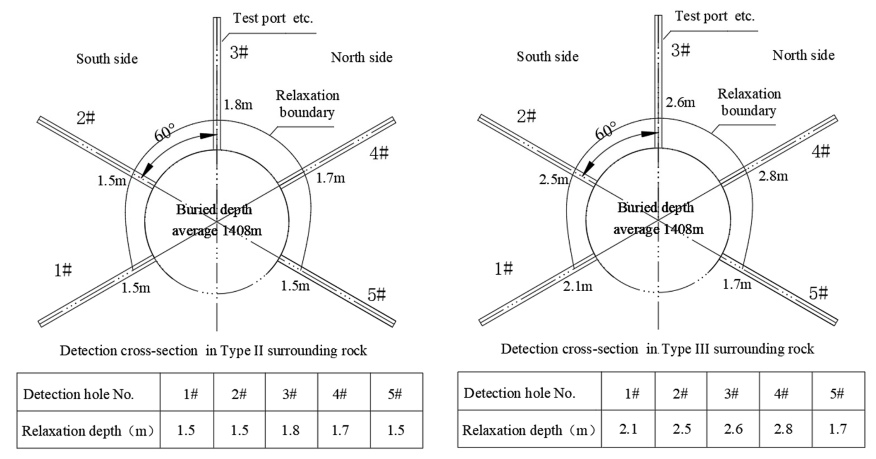
It can be known that in the acoustic detection cross-sections in Type II surrounding rock of 1# and 3# diversion tunnels, the average depths of the low-wave velocity zones in five parts, i.e., the north wall, the north arch shoulder, the top arch, the south arch shoulder, and the south wall are 1.5 m, 1.7 m, 1.8 m, 1.5 m, and 1.5 m, respectively. The maximum buried depth of the seven acoustic detection cross-sections is 1724 m; the minimum is 935 m, and the average is 1408 m. In the acoustic detection cross-sections in Type III surrounding rock of Jinping 1# and 3# diversion tunnels, the average depths of the low-wave velocity zone in five parts, i.e., the north wall, the north arch shoulder, the top arch, the south arch shoulder, and the south wall are 1.7 m, 2.8 m, 2.6 m, 2.5 m, and 2.1 m, respectively. The maximum buried depth of the seven acoustic detection cross-sections is 1636 m; the minimum is 1319 m, and the average is 1474 m.
Based on the above statistical results, the average relaxation depths of surrounding rock in Types II/III surrounding rock acoustic detection cross-sections of Jinping 1# and 3# diversion tunnels are illustrated in
Figure 5.
A group of microscopic mechanical parameters obtained after hundreds of parameter tests are listed in
Table 4 based on the calibration method for microscopic parameters of the model mentioned before, with reference to the ground stress field characteristics of Jinping deeply buried tunnels by Itasca Company, and the PFC method was used to describe the mechanical characteristics of Jinping Type II marble [
37].
In
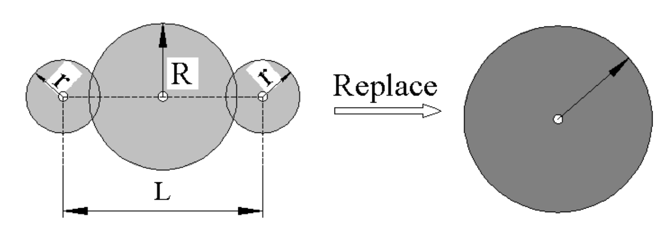
Table 4, the morphological characteristics and related geometric dimensions of cluster units for the replacement of the round particles in the BPM model are shown in
Figure 6. It should be noted that some contacts unbonded are reserved in the CPM model medium in the parameter verification process to reflect the initial defect state of natural rock materials.
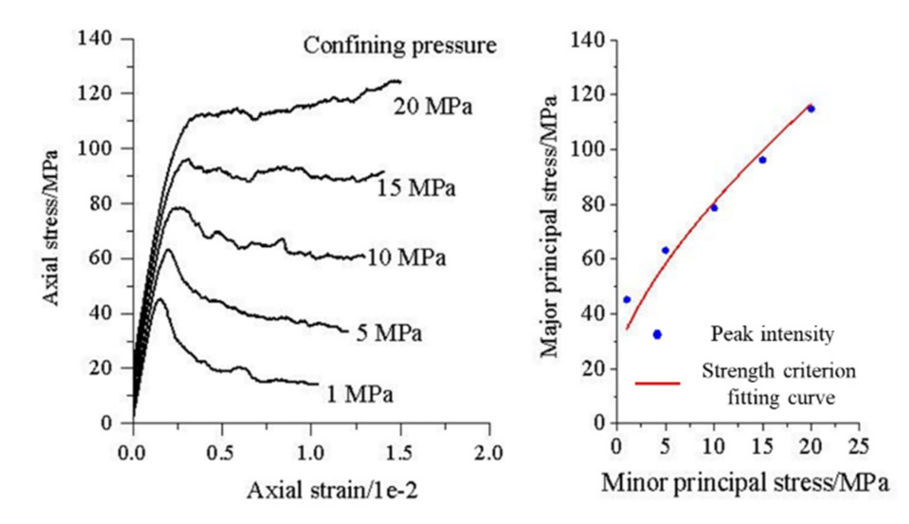
The compression test results of Jinping Type II marble model specimens described by the microscopic parameters in
Table 4 under different confining pressures are shown in
Figure 7. The left diagram in
Figure 7 is the stress–strain curves of the model specimens under different confining pressures, and the right diagram in
Figure 7 is the fitting results of the peak strength and the Hoek–Brown failure criterion of the model specimens under different confining pressures. It can be seen that the PFC numerical test results display brittle characteristics of the model medium under low confining pressure (such as 1 MPa). When the confining pressure rises to about 10 MPa, the model medium is of obvious ductile characteristics. When the confining pressure jumps to about 15 MPa, the model medium presents obvious plastic characteristics. The above test results of model specimens suggest that the brittle-ductile-plastic transformation characteristics of Jinping Type II marble are reasonably described by the microscopic parameters shown in
Table 4.
The on-site rationality of “numerical material” was verified by adopting the “generalized” acoustic detection results of Type II marble.
Figure 8 is the calculation results of excavation damage depth of Type II marble cross-sections under the condition of 1408 m depth based on the microscopic parameters of CPM model.
It can be seen from
Figure 8 that after tunnel excavation, the micro-cracks are more developed in the north arch shoulder and top arch and the south arch foot, and the depth of zone with relatively developed cracks is about 1.8 m, which is basically consistent with the depth of the low-wave velocity zone at the north arch shoulder of the target cross-section shown in
Figure 8.
Similar to the PFC microscopic parameters calibration method of Type II marble, the PFC microscopic parameters of Jinping Type III marble are also given in
Table 4. It should be noted that CPM particles account for 80% and standard circular particles account for 20% in the model medium. In addition, some contacts unbonded are reserved in the model medium to reflect the initial defect characteristics of natural rock materials.
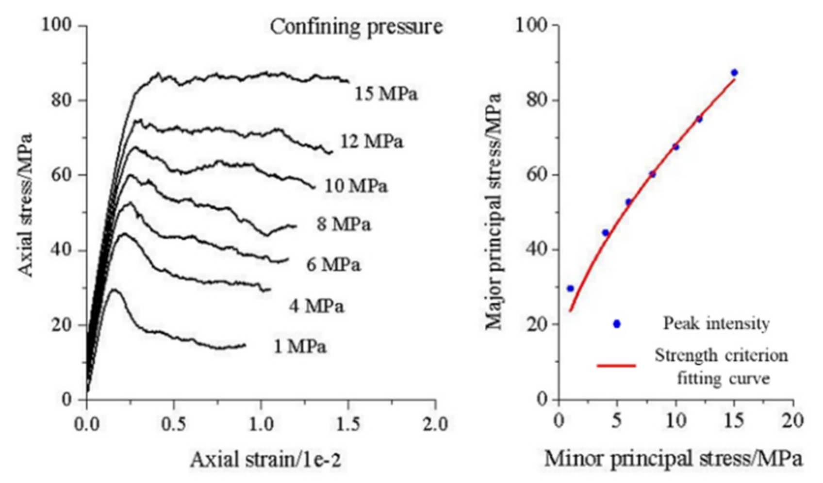
The compression test results of Jinping Type III marble model specimens under different confining pressures described by the microscopic parameters in
Table 4 are shown in
Figure 9. The left diagram in
Figure 9 is the stress–strain curve of the model specimens under different confining pressures, and the right diagram in
Figure 9 is the fitting results of the peak strength and the Hoek–Brown failure criterion of the model specimens under different confining pressures. The test results also reveal the brittle characteristics of Type III marble model medium at a low confining pressure. When the confining pressure increases to about 6 MPa, the model specimen displays certain ductile characteristics. When the confining pressure continues to rise to about 12 MPa, the model specimen shows obvious plastic properties. It can be seen that the brittle-ductile and ductile-plastic transformation confining pressures of Jinping Type III marble is slightly smaller than that of Jinping Type II marble, and its brittle-ductile-plastic transformation characteristics are reasonably described by the microscopic parameters shown in
Table 4.
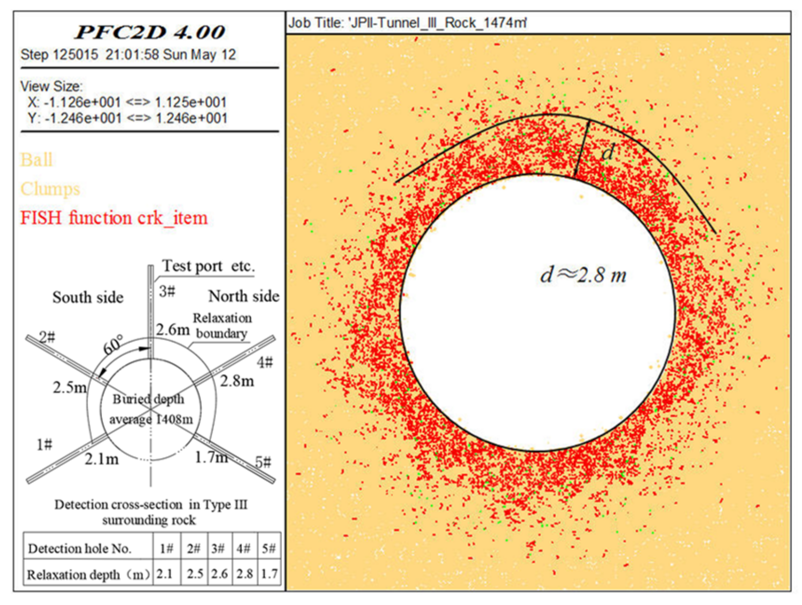
Similar to the on-site verification method of Jinping Type II marble PFC model medium, the on-site rationality of Jinping Type III marble PFC model medium was also verified by adopting the acoustic detection results of Type III marble after “generalization”.
Figure 10 shows the calculation results of excavation damage depth of Type III marble cross-section under the condition of 1474 m depth through the above PFC model microscopic parameters. Due to the decrease in rock quality, the damage depth and micro-crack development density of surrounding rock after tunnel excavation increase remarkably. That is, the depth and degree of surrounding rock excavation damage rise. Overall, the damage cracks are developed in the north arch shoulder and top arch, and the south arch foot. The depth of the zone with relatively developed cracks is about 2.8 m, which is basically consistent with the depth of the low-wave velocity zone at the north arch shoulder of the target cross-section in
Figure 10.
The above numerical test results show that the PFC model medium material of Jinping Types II/III marble shown in
Table 4 can meet the description of Types II/III marble by the Hoek–Brown failure criterion and the acoustic detection results of the relaxation depth of surrounding rock on site. Moreover, the model specimen can naturally reflect the brittle-ductile-plastic transformation characteristics with the increase in confining pressure. Therefore, it can be considered that the PFC microscopic parameters have the ability to characterize the macroscopic and microscopic mechanical characteristics of Jinping Types II/III marble, and the results well disclose the excavation damage characteristics of deeply buried tunnel surrounding rock. It can also provide a reasonable basis for the prediction of the fracturing damage characteristics of surrounding rock under TBM excavation under the conditions of Types II/III rock mass in deeply buried marble tunnel sections.
It should be noted that, in view of the randomness of joint fissure distribution and the influence of other factors, the quality of rock mass on site varies greatly. Even if the same Class III wall rock section is buried at a similar depth, the distribution characteristics of the low wave velocity zone on the section may be significantly different, which can be seen from
Table 2 and
Table 3. This is why the acoustic testing results of the relaxation depth of the surrounding rock on site should be homogenized as the on-site basis for parameter verification. This treatment is equivalent to that the uniaxial compressive strength of rock is not the test result of a certain specimen, but the average value of the test results of many specimens. Accordingly,
Figure 8 and
Figure 10 are the comparison results of the meso parameters of Class II/III marble and the acoustic monitoring section after field homogenization, which are equivalent to the field verification. The results show that the meso parameters of Class II/III marble in
Table 4 can reasonably describe the physical and mechanical properties of Class II/III marble, and are consistent with the field test results of the low wave velocity zone of the tunnel surrounding rock after excavation, which can be used to simulate the damage characteristics of the surrounding rock in the deep tunnel section of TBM excavation.
5. Excavation Damage Characteristics of Surrounding Rock in Deeply Buried Tunnel Sections
The verification and field verification of the microscopic parameters of Jinping II/III marble CPM model show that that the PFC model medium material in
Table 4 can reasonably describe the physical and mechanical properties of Types II/III marble, and are consistent with the on-site test results of the low-wave velocity zone of the tunnel surrounding rock after excavation. This lays a solid foundation for the simulation study of surrounding rock excavation damage characteristics of the TBM excavation of Jinping deeply buried marble tunnel sections.
The prediction of surrounding rock damage depth of TBM excavation in Jinping deep marble tunnel sections basically coincides with the calculation process of on-site verification of PFC model parameters. The difference is that the initial on-site stress needs to be adjusted according to the variation of buried depth.
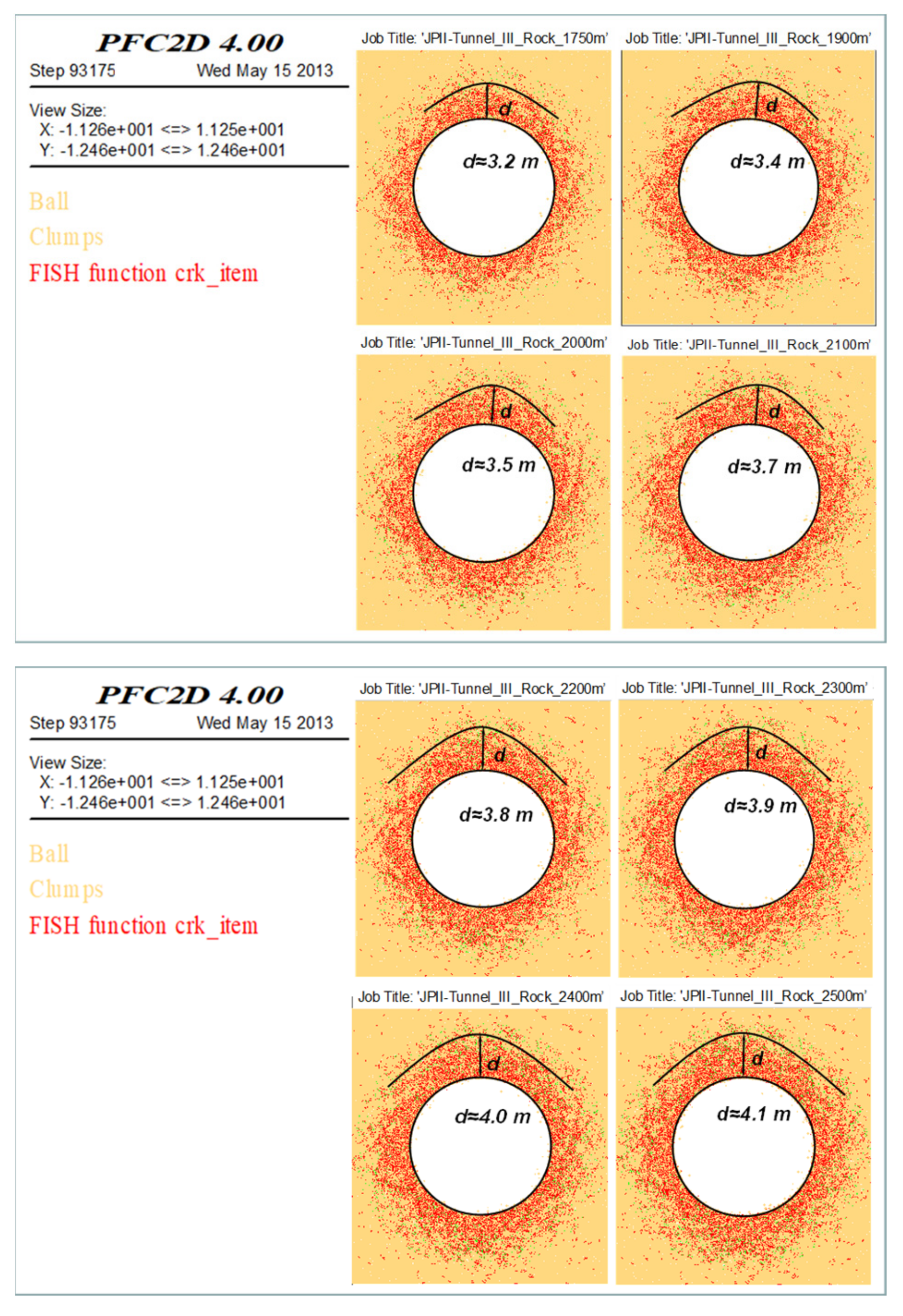
Figure 11 and
Figure 12 are the distribution characteristics of surrounding rock excavation damage in TBM excavation of Types II/III marble tunnels respectively under the conditions of 1750 m, 1900 m, 2000 m, 2100 m, 2200 m, 2300 m, 2400 m, and 2500 m. Overall, the EDZs of surrounding rock of Types II/III marble sections are unevenly distributed around Jinping tunnels, and the largest EDZ is from the top arch to the north arch shoulder. With the increase in buried depth, the depth and degree of surrounding rock excavation damage rise, and the increase in damage degree is mainly illustrated by the increase in crack density.
According to the calculation results, the statistical results of the maximum excavation damage depth of surrounding rock under TBM excavation condition in Jinping deeply buried tunnel sections are given in
Table 5.
The above prediction results suggest that under the same buried depth condition, with the decrease in rock quality, the EDZ depth and damage degree of surrounding rock rise. Overall, the maximum damage depth of Jinping Type III surrounding rock is about 1.0 m larger than that of Type II surrounding rock, which is basically consistent with the acoustic detection results obtained on site.
It should be noted that the above statistical results of excavation damage depth of surrounding rock were directly measured based on the calculation. Theoretically, this method may not be accurate enough, but in terms of engineering application, the error is acceptable.
6. Conclusions
In view of the excavation damage characteristics of tunnel surrounding rock of Jinping deeply buried marble, the PFC microscopic parameters of Types II/III marble tunnels were simulated and calibrated with the aid of PFC2D program according to the acoustic detection results of tunnel cross-sections under the condition of TBM obtained on site. Therefore, the excavation damage characteristics of surrounding rock of deeply buried sections in Jinping diversion tunnels were simulated. The main conclusions obtained are as follows:
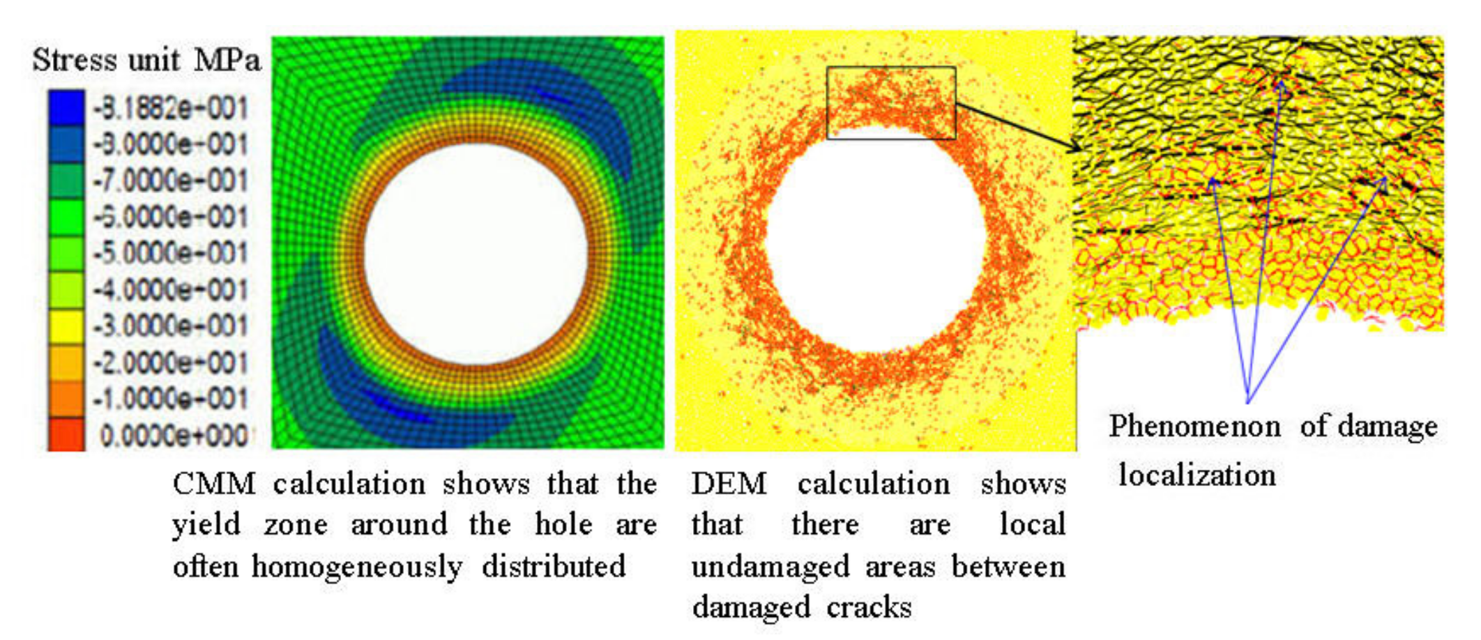
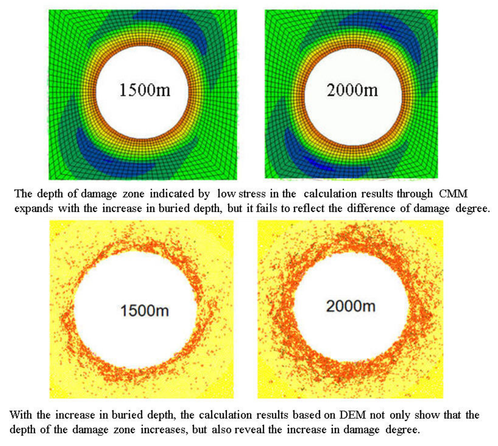
(1) From the perspective of rationality of the damage research method, CMM has inevitable defects in describing some mechanical problems of rock mass. For example, it is not applicable to describing the discontinuous mechanical problems of rock mass. Instead, indirect methods have to be adopted to deal with some complex mechanical behaviors caused by the fracturing of surrounding rock. Therefore, the DMM-based PFC program is obviously superior in the study on excavation damage problem of Jinping deeply buried tunnels.
(2) In the acoustic detection results of the relaxation depth of the tunnel cross-sections, even the detection results of different test holes in the same cross-section may differ much for the following reasons: the influence of the difference in rock quality between cross-sections, structural plane, and local stress field and the large dispersion of the relaxation depth of the cross-sections. Therefore, acoustic detection results of the relaxation depth should be “generalized”: the structural plane in the rock mass is homogenized. That is, when the influence of the structural plane is reflected in the integrity index of the rock mass, the “homogenized” calculation results of the model should be consistent with the on-site test results under “general conditions”.
(3) Based on the “generalized” analysis on the acoustic detection results of tunnel cross-sections under the condition of TBM excavation, the PFC microscopic parameters of Jinping Types II/III marble were simulated and calibrated. The results disclose that the obtained PFC model material of Jinping Types II/III marble conforms to not only the description of Jinping Types II/III marble in deeply buried tunnels by the Hoek–Brown failure criterion, but also the acoustic test results of the relaxation depth of surrounding rock under “general conditions”. Meanwhile, the model specimen can naturally reflect the brittle-ductile-plastic transformation characteristics with the increase in confining pressure.
(4) The EDZs of surrounding rock of Types II/III marble sections in Jinping tunnels are unevenly distributed around the tunnels, with the largest EDZ being from the top arch to the north arch shoulder. With the increase in buried depth, the EDZ depth and damage degree of surrounding rock increase. With the decrease in rock quality, the EDZ depth and damage degree of surrounding rock increase. Overall, the maximum damage depth of Type III surrounding rock is about 1.0 m larger than that of Type II surrounding rock under the same buried depth, which is basically consistent with the detection results of the relaxation depth of surrounding rock. The simulation well discloses surrounding rock excavation damage characteristics of Jinping deeply buried tunnels.
The methods and contents in this research can provide reference for the study on excavation damage of rock mass and its evolution mechanism as well as for surrounding rock stability analysis and support optimization design of deeply buried rock mass engineering.
The actual site conditions include the influence of fissure water, which has not been carried out in the software for the time being. Due to the efficiency of the software calculation, this study only uses the two-dimensional PFC model, and the subsequent consideration is to use the three-dimensional PFC model to further study such problems.
