Article

Decoupling Characteristics and Torque Analytical Model of Sharing-Suspension-Windings Bearingless Switched Reluctance Motor Considering Flux-Linkage Saturation

1
The National Engineering Research Center of Electric Vehicles, Beijing Institute of Technology, Beijing 100081, China
2
The Beijing Spacecrafts, Beijing 100094, China
3
China Academy of Railway Sciences Co., Ltd., Beijing 100081, China
*
Author to whom correspondence should be addressed.
Sustainability 2022, 14(24), 16633; https://doi.org/10.3390/su142416633
Submission received: 8 November 2022 / Revised: 3 December 2022 / Accepted: 9 December 2022 / Published: 12 December 2022
(This article belongs to the Special Issue Emerging Research in Intelligent New Energy Vehicles)

Abstract

:
As its name indicates, the bearingless switched reluctance motor does not have windings or permanent magnets on the rotor. This has the advantages of simple structure, high reliability and easy control. The sharing-suspension-windings bearingless switched reluctance motor inherits the above characteristics, and has obvious advantages in the research field of bearingless motors with its motor structure of decoupling torque and radial force. In this paper, the sharing-suspension-windings bearingless switched reluctance motor is taken as the research object. The finite element model of the sharing-suspension-windings bearingless switched reluctance prototype is established. The electromagnetic characteristics of the prototype are analyzed. As the premise of motor suspension, the structural decoupling of torque and radial force is analyzed and experimentally verified. Then, the flux-linkage saturation of the motor is derived at the position where the stator and rotor are completely aligned and the stator and rotor are completely unaligned. The torque model of the motor is derived based on the flux-linkage saturation, and the accuracy of the model is verified by the fitting comparison between the theory and the finite element simulation. It lays a theoretical foundation for the subsequent structure optimization design research of the sharing-suspension-windings bearingless switched reluctance motor.

1. Introduction

High-speed motors are widely applied in social life, but the high-speed and ultra-high-speed operation of motors is limited by the wear and heating of traditional mechanical bearings. The appearance of bearingless motors broadens the research idea of the high-speed motor. As bearingless switched reluctance motor has the advantages of simple structure, high reliability, and ease of control. The sharing-suspension-windings bearingless switched reluctance motor has obvious advantages in the research field of the bearingless motor, such as the outstanding motor structure which makes the torque and radial force decouple, low hardware cost, and simple control method [1,2,3,4,5].
Professor R. Furuichi first put forward the concept of bearingless switched reluctance machines. Then K. Hismad, a Japanese scholar, analyzed the radial force distribution generated by bearingless switched reluctance machines under different stator winding modes. In 1998, M. Tememoto et al. published an article pointing out that the main winding current, rotor position and suspension winding current have an impact on the radial force received by the rotor of a magnetically suspended switched reluctance motor. After that, many international experts and scholars began to pay more attention to the bearingless switched reluctance motor technology, such as the Federal Institute of Technology in Switzerland, Ibaraki University and Tokyo Institute of Technology in Japan, and the University of Kentucky in the United States. Scholars have laid a good foundation for more than 30 years of research on bearingless switched reluctance machines. At present, all kinds of motor structures have achieved preliminary suspension operation in a laboratory environment [6,7,8,9,10,11,12,13]. In the research process of motor optimization design and control strategy, the torque model based on flux-linkage saturation is a very important research basis and premise. Usually, the magnetic-equivalent circuit method [14] and the Maxwell stress-tensor method [15] are adopted to obtain the torque analytical model considering magnetic saturation, but the model is deduced for motor control rather than for motor design.
In this dissertation, the sharing-suspension-windings bearingless switched reluctance motor is taken as the research object. The finite element model of the sharing-suspension-windings bearingless switched reluctance prototype is established. The electromagnetic characteristics of the prototype are analyzed, the characteristic verification experiment of the prototype is carried out. The decoupling characteristics between torque and radial force on the structure of the sharing-suspension-windings bearingless switched reluctance prototype are verified. Then, the saturated flux-linkage of the switched reluctance motor is derived at the position where the stator and rotor are completely aligned and completely unaligned, and the torque model based on the flux-linkage saturation is derived. Finally, the accuracy of the model is verified. It lays a theoretical foundation for the subsequent structural optimization design research of the sharing-suspension-winding bearingless switched reluctance motor.

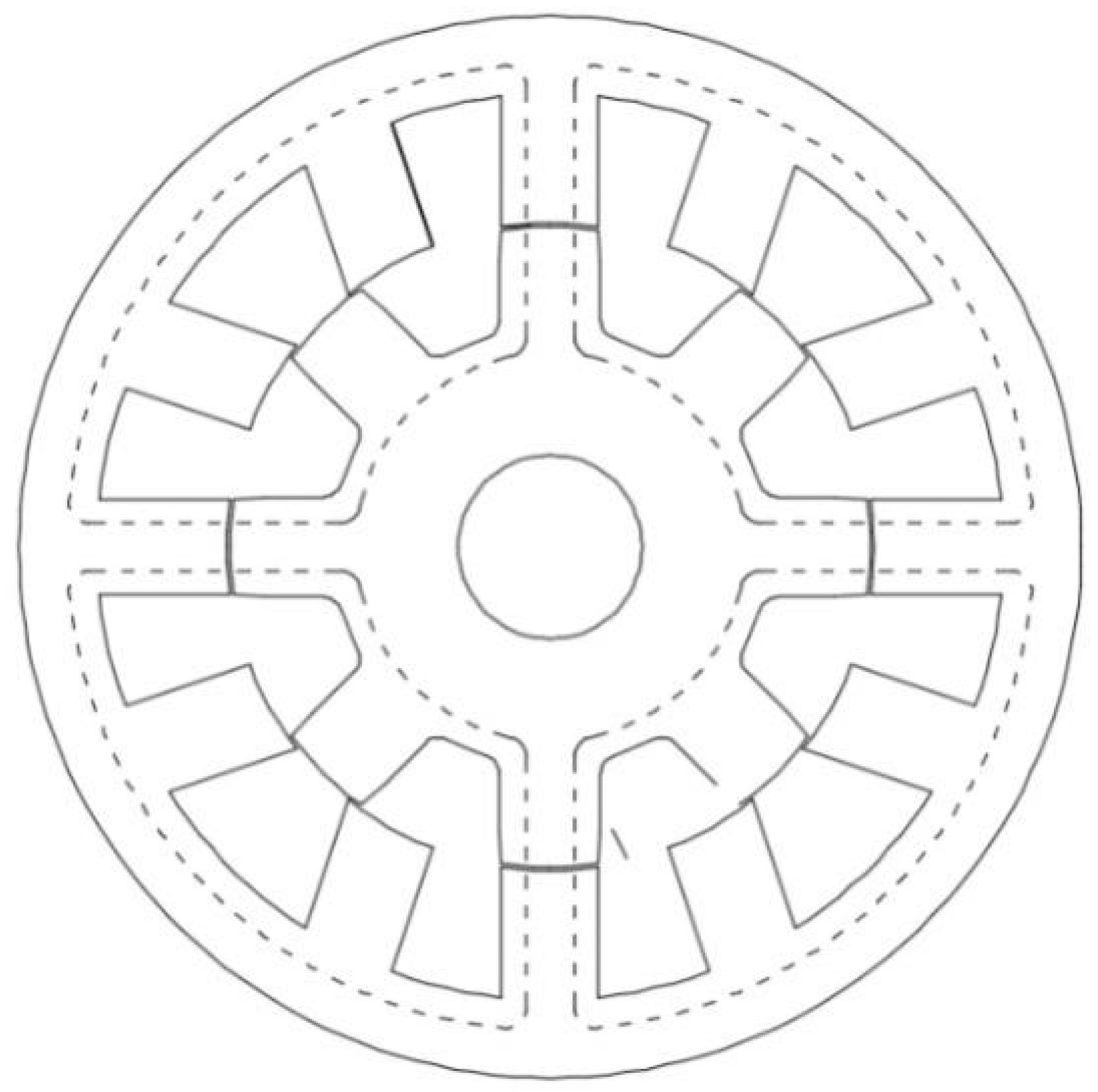
2. Sharing Suspension Winding Bearingless Switched Reluctance Motor

The sharing suspension winding bearingless switched reluctance motor is a kind of double-winding bearingless switched reluctance motor. Its stator and rotor are made of a silicon steel sheet by a stacking process. The rotating winding of the motor is wound on each pole of the stator in a centralized winding mode, and the suspension winding coil is wound on each pole of the stator in a group, although there is no winding on the rotor. In this way, the core structure is similar to that of the ordinary switched reluctance motor, except that the design of the fixed suspended winding tooth pole is closer to the non-fixed suspended winding tooth pole (The three tooth poles in the X-axis positive direction in Figure 1, phase A and phase C are close to phase B), in order to provide more space for the placement of the suspension winding. The left and right windings in the X-direction are connected in series to form the X-direction suspension winding, and the two windings in the Y-direction are connected in series to form the Y-direction suspension winding [16,17,18,19,20,21,22,23].
The working principle of the motor is similar to that of the double-wound bearingless motor. Taking the rotor position in Figure 1 as an example of energized phase B rotating winding, if the rotor moves forward to the X-direction, the magnetic flux in the left air gap of the rotor is smaller than that in the right air gap. The asymmetric magnetic flux will generate a radial force in the X-axis positive direction, so it is necessary to pass a negative current through the X-direction suspension winding to generate a force in the X-axis negative direction to offset the positive radial force. When the negative current is applied to the suspension winding in the X-direction, the air gap flux on the left side of the rotor is strengthened, and the air gap flux on the right side is weakened. When the left air-gap flux is greater than the right air-gap flux, the rotor will be subjected to a radial force in the X-axis negative direction to pull the rotor back to the geometric center of the motor. Vice versa, when a large enough positive current is applied to the suspension winding in the X-direction, the rotor will be subjected to the radial force in the X-axis positive direction. Therefore, as long as the size and direction of the suspension winding current in X- and Y-direction can be accurately adjusted, the controllable radial suspension force can be generated.
When the motor runs in rotation, the total magnetic flux of the suspension winding passing through the polar surface of the rotor in each direction will not change with the rotation of the rotor in the four positive directions (X positive, X negative, Y positive and Y negative). Therefore, the suspension winding will not affect the torque when it works, so that the torque and the suspension force are decoupled on the motor structure. Since the motor only needs two sets of suspension windings, compared with the general double winding or single winding bearingless switched reluctance motor, both the control algorithm and the power devices and their supporting auxiliary circuits are greatly simplified. Moreover, because of the simple winding mode of the motor winding, this winding mode can be extended to other multiphase motors.

3. Finite Element Simulation Analysis of the Prototype

The finite element method is one of the most effective methods to solve the magnetic field of the motor. In this section, based on the finite element software ANSYS and according to the structural parameters of the prototype, the finite element model of the motor will be built to analyze its electromagnetic characteristics. Figure 2 shows the scheme of prototype structure.
Table 1 shows the structural parameters of the sharing-suspension-winding bearingless switched reluctance motor. The rated power of the motor is 1.5 kw and the rated speed is 5000 rpm/min.

3.1. Motor Torque and Flux-Linkage Characteristics

The rotating winding is made of 0.8 mm wire diameters’ double winding, and the current RMS value of the prototype is I ≈ 5.02 A. The ideal square wave current amplitude required to generate the rated torque is obtained by I m * = 2 I 7.10 A. The quality of rotor is mr = 1.72 kg. The (0–1.5 A) current of motor suspension winding in X- and Y-direction is taken. Where the center line of the stator slot coincides with the center line of the rotor pole is the 0 degree position of the rotor position angle θ. Motor conduction angle is θ c = (0~15°).
Figure 3a shows motor torque VS angle when the motor suspension windings in X- and Y-directions are both 0 A and the windings in phase B are imb = 0–6.5 A. It can be seen that the torque is already almost zero at θ = 15°. Since the motor winding still needs a certain time to flow free after the inverter switch tube is turned off, the control strategy should meet the requirement of turning off before θ = 15° to avoid negative torque generation of the motor. Figure 3b shows phase B winding flux variation with winding current when the suspended windings in X- and Y-directions of the motor are both 0 A and the rotor position angles θ are −7.5° and 15°. As the motor is not saturated at the rated current, the flux varies linearly with the current at the two positions of the minimum and maximum flux linkage. Figure 3c shows motor torque changing with rotor angle when the winding current of phase B is imb = 6 A, the suspended winding currents in the X-direction are 0, 0.5, 1 and 1.5 respectively, and the suspended winding current in the Y-direction is iy = 0 A. It can be seen that the four curves in Figure 3c almost coincide, indicating that the motor torque does not change with the current of the suspended winding, verifying that the motor structure torque and radial suspension force are decoupled in structure.

3.2. Motor Radial Suspension Force Characteristic

Figure 4a shows the suspension force in X-direction changing with the suspension winding current in X-direction when the winding current in phase B is imb = 6 A, the suspension winding current in Y-direction is iy = 0 A, and θ is −7.5, 0, 7.5 and 15, respectively. It can be seen that the suspension force in the X-direction increases positively with the current of the suspension winding, and the relationship is linear. The prototype can generate the radial suspension force to meet the control needs under the action of a small number of ampere-turns. Figure 4b shows the suspension force in X-direction changing with the rotating winding current when the winding current in phase B is imb = 6 A and the suspension winding current in Y-direction is iy = 0 A and θ is −7.5, 0, 7.5 and 15, respectively. It can be seen that the rotating winding current has an effect on the radial suspension force, and the radial suspension force increases positively with the rotating winding current and has a linear relationship. Figure 4c shows the suspension force in X-direction changing with the rotor angle when the winding current in phase B is imb = 6 A, the suspension winding current in X-direction is 0, 0.5, 1 and 1.5 respectively, and the suspension winding current in Y-direction is iy = 0 A. It can be seen that the suspension force in the X-direction is small and basically unchanged in the rotor −7.5°~−2.5° position range. In the range of −2.5°~15°, the suspension force in X-direction increases positively with the angle of the suspended rotor, and the relationship is linear. Therefore, in order to obtain sufficient radial suspension force, the opening angle should not be set too small in the angle optimization control process. Figure 4d shows the suspension force in Y-direction change with the current of the suspension winding in Y-direction when the winding current in phase B is imb = 6 A, the suspension winding current in X-direction is ix = 1 A, and the rotor angle is −7.5, 0, 7.5 and 15, respectively. It can be seen that the suspension force increases positively with the current of the suspension winding in the Y-direction, and the relationship is linear. Figure 4e shows the suspension force in Y-direction change with the suspension winding current in X-direction when the winding current in phase B is imb = 6 A, the suspension winding current in Y-direction is iy = 1 A, and the rotor angle is −7.5°, 0°, 7.5° and 15°, respectively. It can be seen that with the increase in the suspension winding current in the X-direction, the suspension force in the Y-direction basically does not change, indicating that the suspension force in the X- and Y-direction generated by the suspension winding current of the structure is decoupled.

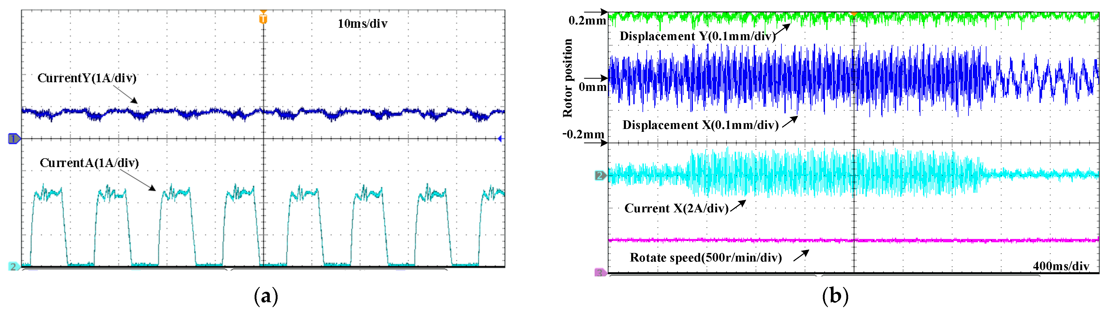
4. Experiments on Decoupling Characteristics of Motors

The torque and the radial suspension force of the sharing-suspension-windings bearingless switched reluctance motor are decoupled in structure. In this section, the decoupling characteristics of motor torque and suspension force are verified by the phenomenon that the speed remains constant in the case of different suspension winding current.
In order to minimize the influence on the speed when the rotor reaching the edge, the motor runs without load, and the radial displacement in the X-direction is controlled to move in the center. A constant current is applied in the Y-direction to generate a constant radial force to make the rotor reach the edge. The system controls the rotating winding with constant current, and stabilizes the speed to the given speed by adjusting the supply voltage.
During the experiment, the floating winding current in Y-direction is set to 0.8 A, and the upper limit of rotating winding current is 2.5 A, as shown in Figure 5a. Oscilloscope channel 2 shows the current waveform of rotating winding in phase A. As shown in Figure 5b, the radial displacement in the Y-direction is 0.2 mm at the farthest end of the Y-axis forward direction, and the power supply voltage of the rotating winding is adjusted to stabilize the speed at 500 r/min. The X-direction controller adjusts the radial displacement in the center of the X-direction, and the initial supply voltage of the suspension winding is 3 V (the supply voltage of the suspension winding supplies power to the suspension winding in both the X- and Y-directions). The supply voltage of the suspension winding is increased to 5 V at about 640 ms, and then reduced to 2 V at about 2.8 s. It can be seen that the radial displacement in the X-direction and the current of the suspension winding first increase and then decrease with the change of the supply voltage, but the motor speed does not change. Thus it can be proved that the rotational speed and radial suspension force of the sharing-suspension-winding bearingless switched reluctance motor are decoupled in structure.

5. Calculation of Saturation Flux-Linkage

The influence of the suspension winding current on the electromagnetic torque of the sharing-suspension-windings bearingless switched reluctance motor is very small. In this section, the saturated flux-linkage of the switched reluctance motor is firstly derived at the position where the stator and rotor are completely aligned and completely unaligned, and then the torque model based on the saturated flux-linkage is derived, and finally the accuracy of the model is verified.

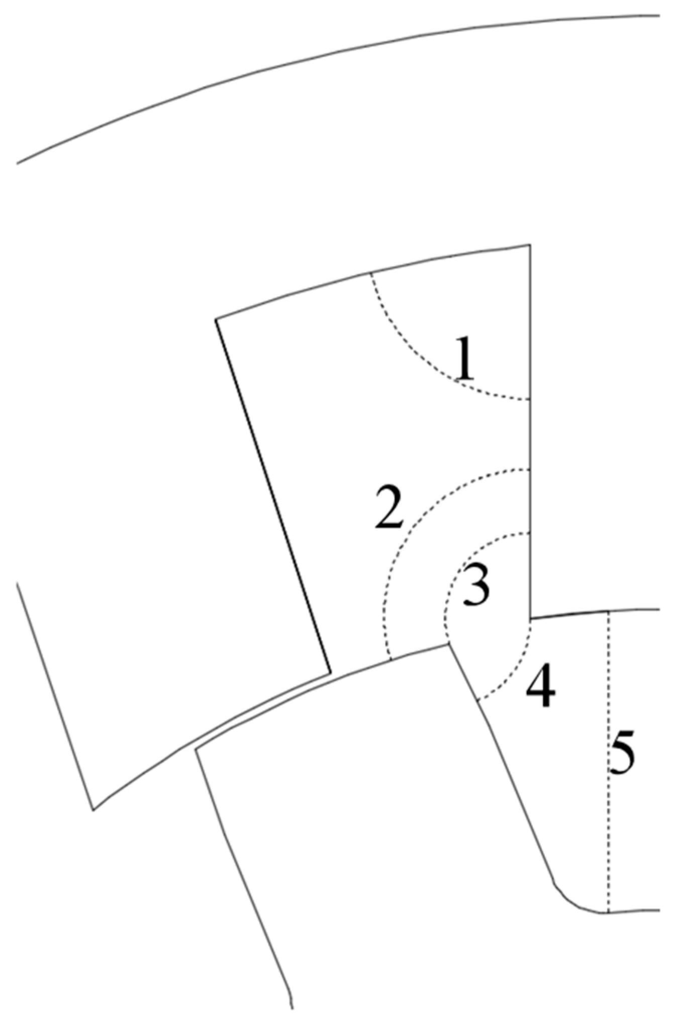
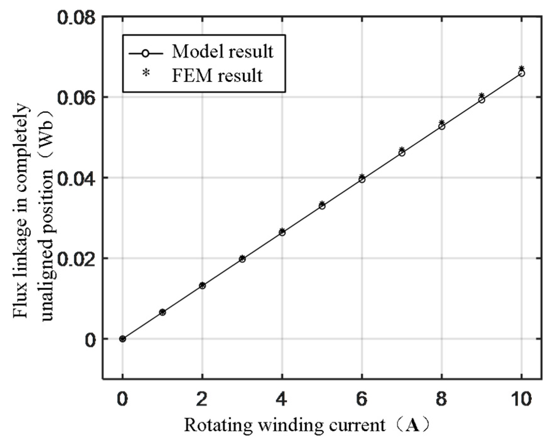
5.1. Flux-linkage at Complete Unalignment of Stator and Rotor

Figure 6 shows the approximate magnetic field line path, and five magnetic field lines l1, l2, l3, l4 and l5 are selected for approximation. Since the distribution of the magnetic field lines at this position is completely symmetric in both the transverse and longitudinal directions, the total flux-linkage can be obtained.
ψ = 4 ( ψ 1 + ψ 2 + ψ 3 + ψ 4 + ψ 5 )
where ψ1, ψ2, ψ3, ψ4 and ψ5 are the flux-linkage in regions 1, 2, 3, 4 and 5, respectively.
When the rotor is at this position, there is basically no saturation area in the core, so the magnetic potential drops on the air gap reluctance of the motor. So
ψ = N 2 μ 0 l Fe ( P 1 + P 2 + P 3 + P 4 + P 5 ) i
P 1 = a m 2 4 ω 2 ( 2 υ + μ )
P 2 = 2 π [ ln n h + 2 ( n h ) y w υ ( n 2 h 2 ) 4 ( w υ ) 2 ( π w υ 2 y 2 ) ( n 3 h 3 ) y π 6 ( w υ ) 2 + ( n 4 h 4 ) π 2 64 ( w υ ) 2 ]
P 3 = 2 τ r ln 2 tan ( τ r β r ) + π ( τ r β r ) 2 tan ( τ r β r ) + π 2 ( τ r β r ) β r
P 4 = 2 π τ r ln 2 g i h ( π τ r )
P 5 = p + h g i 2 π τ r
According to the motor structure parameters in Table 1 (In order to improve the saturation degree of the prototype, the turns of the rotating winding is increased to 70). Using the finite element simulation, the simulation results and model comparison curves shown in Figure 7 are obtained. It can be seen that the results derived by the model formula are very close to the finite element simulation results.

5.2. Flux-Linkage at Complete Alignment of Stator and Rotor

Figure 8 shows the distribution of the magnetic field line at the position where the stator and rotor pole center lines are fully aligned and the current of the main winding of phase B is 4 A. When the rotor is at this position, the magnetic circuit of the motor is most saturated, and the saturation phenomenon cannot be ignored.
According to the motor structure, it can be obtained.
The width of the stator pole:
b ps = β sr D si
where βsr is the radian form of stator pole arc βs.
The width of the rotor pole:
b pr = β rr D a
where βrr is the radian form of rotor pole arc βr.
Air gap cross-sectional area:
S g = 1 2 ( b ps + b pr ) 2 D si 2 l Fe
Length of air gap:
l g = g
Stator yoke cross-sectional area:
S cs = h cs l Fe
Length of stator yoke:
l cs = D s h cs 2 π 2
Rotor yoke cross-sectional area:
S cr = h cr l Fe
Length of rotor yoke:
l cr = ( D si 2 g i h cr 2 ) π 2
Stator pole cross-sectional area:
S ts = b ps 2 l Fe
Length of stator pole:
l ts = D s D si 2 h cs
Rotor pole cross-sectional area:
S tr = b pr 2 l Fe
Length of rotor pole:
l tr = D a 2 h cr
According to the Ampere-loop theorem, the magneto-motive force of each pole-excited pair can be obtained.
F = 2 N ph i = 2 H ts l ts + 2 H g l g + 2 H tr l tr + H cr l cr + H cs l cs
The stator pole flux density is set to Bts, getting the magnetic flux.
Φ = B ts S ts
Since the magnetic flux is equal everywhere.
Rotor pole flux density:
B tr = Φ / S tr = B ts S ts / S tr
Air gap flux density:
B g = Φ / S g = B ts S ts / S g
Stator yoke flux density:
B cs = Φ / S cs = B ts S ts / S cs
Rotor yoke flux density:
B cr = Φ / S cr = B ts S ts / S cr
The robust least squares method is used to fit this curve with magnetic flux density B as the variable, and the relationship between magnetic flux density B and magnetic field strength H can be obtained.
H = 0 . 03799 e 7 . 002 B
Figure 9 shows the comparison between the fitting equation (26) and the actual magnetization curve.
The root mean square error of the fitting result relative to the actual value is 22.2662, and the R-square value is 0.9999. It can be seen that the fitting accuracy can meet the requirements, and the fitting equation can approximately express the 50TW600 DC magnetization curve.
Using Equation (26) and replacing Hts, Htr, Hcr, and Hcs by Bts in Equation (20), it can be obtained.
2 N ph i = 2 × 2.046 e 4.901 B t s l ts + 2 B ts S ts μ 0 S g l g + 2 × 2.046 e 4.901 B ts S ts S tr l tr + 2.046 e 4.901 B ts S ts S cr l cr + 2.046 e 4.901 B ts S ts S cs l cs
Although (27) is a transcendental equation, it is not difficult to see that this equation is a monotonically increasing function. Therefore, assuming that Bts is zero, substitute into Equation (27) and calculate whether the two sides of the equation are equal. If not, we can add a smaller value δ to Bts and substitute it into Equation (27) to calculate the equality. In such an iterative manner, an approximate solution of Equation (27) can be obtained, the accuracy of which depends on the value of δ chosen to be superimposed to Bts.
Figure 10 shows the comparison curves between the finite element simulation results and the model. It can be seen that the model is very close to the simulation results. Since the model does not consider flux leakage and edge flux, the model curves are slightly smaller than the FEM simulation results.

5.3. Electromagnetic Torque of Motor

Figure 11 shows the flux variation with the main winding current at the stator and rotor completely unaligned and completely aligned.
The shaded area surrounded by the two curves is the magnetic co-energy W′ of the motor. Then the electromagnetic torque of the designed motor can be obtained. Based on this, in the process of motor optimization design, the flux linkage of the stator and rotor completely unaligned position and completely aligned position can be calculated according to the equation. The required magnetic co-energy can then be obtained according to the shadow area, and the corresponding ideal square wave current amplitude can be obtained, so as to carry out the subsequent motor optimization design.
T em = N s N r 4 π W

6. Conclusions

In the research process of motor optimization design and control strategy, the torque model based on flux-linkage saturation is a very important research basis and premise. Usually, the magnetic equivalent circuit method and the Maxwell stress tensor method are adopted to obtain the torque analytical model considering magnetic saturation, but the model is deduced for motor control rather than for motor design. In this paper, the electromagnetic characteristics of a sharing-suspension-windings bearingless switched reluctance motor are analyzed by establishing the finite element model. The analysis shows that the prototype can generate the radial suspension force to meet the control needs under the action of fewer ampere-turns, and the radial force increases positively with the position angle of the rotor. The suspension-winding turns of the prototype are selected to be large, which reduce the utilization of the motor. The decoupling characteristics of the motor are tested, and the decoupling characteristics of the torque and radial force in the structure of the sharing-suspension-windings bearingless switched reluctance motor are verified. The flux-linkage saturation is derived at the position where the stator and rotor are completely aligned and completely unaligned. Then the torque model based on the saturated flux is derived, and the accuracy of the model is verified. Based on the obtained equation, in the process of motor optimization design, the flux linkage of the stator and rotor completely unaligned position and completely aligned position can be calculated, and then the required magnetic co-energy can be obtained according to the shadow area, and the corresponding ideal square wave current amplitude can be obtained, so as to carry out the subsequent motor optimization design. This provides a theoretical basis for the subsequent research and application of the sharing-suspension-windings bearingless switched reluctance motor.

Author Contributions

Conceptualization, W.H., Z.W. and Y.H.; methodology, W.H. and Z.W.; software, J.H.; validation, W.H., J.H., Z.W. and Y.H.; investigation, W.H.; writing—original draft preparation, W.H.; writing—review and editing, W.H. All authors have read and agreed to the published version of the manuscript.

Funding

This research was funded by Beijing Institute of Technology Research Fund Program for Young Scholars.

Institutional Review Board Statement

Not applicable.

Informed Consent Statement

Not applicable.

Data Availability Statement

Not applicable.

Conflicts of Interest

The authors declare no conflict of interest.

Nomenclature

Lacore length
mphase number
Ds, Daouter diameter of stator and rotor
Dsiinner diameter of stator
Nphwinding turns
τrrotor pole pitch
ωmotor angular velocity
gisecond air gap (distance from stator pole to rotor slot)
hcs, hcrheight of stator yoke and rotor yoke
bps, bprwidth of stator pole and rotor pole
lFemagnetic core effective length
hrotor length
nrotor speed
μ0vacuum permeability

References

  1. Ye, X.; Wang, Z. Levitation performances analysis of a novel bearingless switched reluctance motor. IEEE Trans. Appl. Supercond. 2021, 31, 5203004. [Google Scholar] [CrossRef]
  2. Wang, Z.; Cao, X.; Deng, Z.; Li, K. Modeling and characteristic investigation of axial reluctance force for bearingless switched reluctance motor. IEEE Trans. Ind. Appl. 2021, 57, 5215–5226. [Google Scholar] [CrossRef]
  3. Wang, Z.; Cao, X.; Deng, Z. Modeling and analysis of radial levitation and axial reluctance force for four degree of freedom bearingless switched reluctance motor. IEEE Trans. Ind. Electron. 2021, 68, 11895–11906. [Google Scholar] [CrossRef]
  4. Zhang, T.; Chen, J.; Zhu, W. Suspension performance analysis on the novel hybrid stator type bearingless switched reluctance motor. IEEE Trans. Magn. 2021, 57, 8203604. [Google Scholar] [CrossRef]
  5. Suna, C.; Zhuang, P.; Li, J.; Li, J. Design and analysis of a 16/6 bearingless switched reluctance motor with segment hybrid rotor teeth. IEEJ Trans. Electr. Electron. Eng. 2020, 15, 939–946. [Google Scholar] [CrossRef]
  6. Zhou, Y.; Jiang, J.; Sun, Y.; Zhu, Z. A dual-phase-conducted type bearingless switched reluctance flywheel motor with hybrid outer rotor. Electron. Lett. 2021, 57, 354–356. [Google Scholar] [CrossRef]
  7. Sun, C.; Li, J.; Ding, H.; Yang, H.; Han, S.; Han, N. Characteristic analysis of a new double stator bearingless switched reluctance motor. IEEE Access 2021, 9, 38626–38635. [Google Scholar] [CrossRef]
  8. Gaafar, M.A.; Abdelmaksoud, A.; Orabi, M.; Chen, H.; Dardeer, M. Performance investigation of switched reluctance motor driven by Quasi-Z-Source integrated multiport converter with different switching algorithms. Sustainability 2021, 13, 9517. [Google Scholar] [CrossRef]
  9. Sahinkaya, M.N.; Abulrub, A.-H.G.; Keogh, P.S.; Burrows, C.R. Multiple Sliding and Rolling Contact Dynamics for a Flexible Rotor/Magnetic Bearing System. IEEE/ASME Trans. Mechatron. 2007, 12, 179–189. [Google Scholar] [CrossRef]
  10. Hao, Z.; Yu, Q.; Cao, X.; Deng, X.; Shen, X. An improved direct torque control for a single-winding bearingless switched reluctance motor. IEEE Trans. Energy Convers. 2020, 35, 1381–1393. [Google Scholar] [CrossRef]
  11. Turk, N.; Bulić, N.; Gruber, W. Nonlinear control of a bearingless flux-switching slice motor with combined winding system. IEEE/ASME Trans. Mechatron. 2020, 25, 152–163. [Google Scholar] [CrossRef]
  12. Schuck, M.; Steinert, D.; Kolar, J.W. Active radial magnetic bearing for an ultra-high speed motor. In Proceedings of the 18th European Conference on Power Electronics and Applications, Karlsruhe, Germany, 5–9 September 2016. [Google Scholar]
  13. Zhu, Z.; Zhu, J.; Zhu, H.; Jiang, Y.; Cheng, M. A novel axial split phase bearingless switched reluctance machine for On-Board flywheel battery. IEEE Trans. Veh. Technol. 2021, 70, 3175–3186. [Google Scholar] [CrossRef]
  14. Hao, Y.; Wang, X.; Cui, R.; Fang, X.; Zhang, W.; Li, Y.; Cheng, D. Torque Analytical Model of Switched Reluctance Motor Considering Magnetic Saturation. IET Electr. Power Appl. 2020, 14, 1148–1153. [Google Scholar] [CrossRef]
  15. Takemoto, M.; Chiba, A.; Akagi, H.; Fukao, T. Radial force and torque of a bearingless switched reluctance motor operating in a region of magnetic saturation. IEEE Trans. Ind. Appl. 2004, 40, 103–112. [Google Scholar] [CrossRef]
  16. Rao, P.N.; Kumar, N.M.; Padmanaban, S.; Subathra, M.S.P.; Chand, A.A. A novel sensorless approach for speed and displacement control of bearingless switched reluctance motor. Appl. Sci. 2020, 10, 4070. [Google Scholar]
  17. Zhu, T.; Cao, X.; Yu, Q.; Deng, Z.; Hao, Z. Direct torque control with phase commutation optimization for single-winding bearingless switched reluctance motor. IEEE Trans. Power Electron. 2022, 37, 13238–14249. [Google Scholar] [CrossRef]
  18. Huang, Y.; Huang, F.; Yuan, Y.; Yang, F.; Xie, K. Design and analysis of a novel bearingless segmented switched reluctance motor. IEEE Access 2019, 7, 94342–94349. [Google Scholar] [CrossRef]
  19. Ahmeda, F.; Kalitab, K. Controllability of radial displacement in bearingless switched reluctance motor using bridge configured winding. Int. J. Appl. Electromagn. Mech. 2020, 63, 133–152. [Google Scholar] [CrossRef]
  20. Takemoto, M.; Yoshida, K.; Itasaka, N. Synchronous reluctance type bearingless motors with multi-flux barriers. In Proceedings of the 4th Power Conversion Conference (PCC-Nagoya 2007), Nagoya, Japan, 2–5 April 2007; pp. 1–3. [Google Scholar]
  21. Takemoto, M.; Iwasaki, S.; Miyazaki, H.; Chiba, A.; Fukao, T. Experimental Evaluation of Magnetic Suspension Characteristics in a 5-axis Active Control Type Bearingless Motor without a Thrust Disk for Wide-gap Condition. In Proceedings of the IEEE Energy Conversion Congress and Exposition, San Jose, CA, USA, 20–24 September 2009; pp. 1–6. [Google Scholar]
  22. Junichi, A.; Ryo, K.; Tomoyasu, T. Reduction of force interference and performance improvement of a consequent-pole bearingless motor. Precis. Eng.-J. Int. Soc. Precis. Eng. Nanotechnol. 2012, 36, 10–18. [Google Scholar]
  23. Jihad, F.; Masachika, K.; Kyohei, K. Approximation of Radial Force in Highly Saturated Region of Switched Reluctance Motor. In Proceedings of the 19th International Conference on Electrical Machines and Systems (ICEMS), Chiba, Japan, 13–16 November 2016; pp. 13–16. [Google Scholar]
  24. Wang, X. A Sharing Suspension Windings Bearingless Switched Reluctance Motor. CN200910078022.9, 7 August 2009. Available online: https://kns.cnki.net/kcms/detail/detail.aspx?dbcode=SCPD&dbname=SCPD0809&filename=CN101478274&uniplatform=NZKPT&v=U-RvtJzoVyVUOEvNK5TfDw0bYufnOWSyJd7cIAB18TTlV6hrlIzrEE9JS-JAs0ZJ (accessed on 7 November 2022).
Figure 1. Magnetic paths of X-direction suspension windings when phase-B is energized.
Sustainability 14 16633 g001
Figure 2. Scheme of prototype structure.
Sustainability 14 16633 g002
Figure 3. Motor torque characteristics (a) Angle VS torque; (b) Rotating winding current VS flux-linkage; (c) Angle and suspension winding current VS torque.
Sustainability 14 16633 g003
Figure 4. Suspension force characteristics (a) Current in the X-direction VS Suspension force in the X-direction; (b) Winding current VS Suspension force in the X-direction; (c) Angle VS Suspension force in the X-direction; (d) Current in the Y-direction VS Suspension force in the Y-direction; (e) Current in the X-direction VS Suspension force in the Y-direction.
Sustainability 14 16633 g004
Figure 5. Waveforms of prototype decoupling characteristic experiment (a) Current of the Y-direction and phase A; (b) Displacement in the X- and Y-direction, current and speed in the X-direction.
Sustainability 14 16633 g005
Figure 6. Approximated flux paths at unaligned position of stator and motor.
Sustainability 14 16633 g006
Figure 7. Flux-linkage result comparison between proposed model and FEM at unaligned position.
Sustainability 14 16633 g007
Figure 8. Approximated flux paths at aligned position of stator and motor.
Sustainability 14 16633 g008
Figure 9. Comparison between the result of fitting and practical value.
Sustainability 14 16633 g009
Figure 10. Flux-linkage result comparison between proposed model and FEM at aligned position.
Sustainability 14 16633 g010
Figure 11. Co-energy of the motor.
Sustainability 14 16633 g011
Table 1. Structure parameters of the prototype [24].
ParametersValue
Stator pole/rotor pole12/8
Rotating winding23 turns
Suspension winding23 turns
Outer diameter of stator110 mm
Inner diameter of stator 67 mm
Stator yoke high8.05 mm
Air gap length0.3 mm
Outer diameter of rotor 66.4 mm
Inner diameter of rotor 19 mm
Rotor yoke high13.1 mm
Stator pole wide10 mm
Rotor pole wide10 mm
Tilt angle of stator pole26.57°
Axial length of rotor62 mm
Rotating winding wire diameter0.8 mm double wrap
Auxiliary winding wire diameter0.8 mm single wrap
Material50TW600
Publisher’s Note: MDPI stays neutral with regard to jurisdictional claims in published maps and institutional affiliations.

