Abstract
The composite T-joint, a typical structural element, is widely used in the fields of aerospace due to their excellent mechanical properties. However, several defects might occur in this material during manufacturing because of the application of co-curing and co-bonding technologies. The existence of the defects results in the reduction in the load bearing capacity, which negatively affects the safety of the structure. In this study, a finite element (FE) model of composite T-joints is established, which is verified by quasi-static tests to investigate the load bearing capacity and failure modes of composite T-joints under bending loadings with different types of defects, including core material defects, radius floating of the fillet, and debonding defects. It is indicated that the failure modes of T-joints with different kinds of defects under bending loadings are similar, i.e., the delamination occurs firstly at the interface between the filling area and the L-rib before expanding to both sides. Meanwhile, the types of defects exert great effects on the load bearing capacity of T-joints, and the debonding defects in the arc area represent the most dangerous one. Furthermore, the orthogonal test method was adopted to analyze the influence of combined defects on the load bearing capacity of T-joints, and the findings reveal that the most sensitive type of defect is the debonding defects, followed by the radius floating of the fillet, and then core material defects. This result indicates that combined defects have a coupling effect on the load bearing capacity of composite T-joints. This study provides theoretical guidance and technical support for the repair of the defects of composite T-joints.
1. Introduction
The composite joint is the key technology of the integrated structure of these materials. This technology, which can significantly reduce the number and weight of the connection parts and improve the connection efficiency, is applied to the main components of the composite materials [1,2,3].
One of the important applications of laminated composites refers to structure application. Joints have become the difficulties in structural design. This is a special case of a 90° joint, which presents a challenging case given the out-of-plane loads. Furthermore, bending loads can be subjected at the joint. Various solutions to this problem have been proposed, usually in the form of T-joint structures [1,4,5].
Out-of-plane joints receive increasing research attention because their stress distribution characteristics and failure mechanisms in practical engineering applications are complicated [6]. The composite T-joint is a typical out-of-plane joint unit with three laminates and a fillet. When these joints are used in operations, they are subjected to tensile, bending, and shearing loads in different directions and magnitudes, and the vibration zenvironment of the composite T-joints is very severe in terms of vibration frequency and amplitude. In addition, T-joints are often affected by environmental factors, such as humidity, salt spray, and high and low temperatures. Given the diversity of process preparation and use conditions, various types of defects exist in T-joints [1], and such defects have a significant effect on the failure mechanism and load bearing capacity of the composite T-joints. In consideration of the weak bending bearing capacity of composite T-joints [6], the effect of defects under bending load on their bearing capacity should be investigated.
Researchers conducted a series of study on the influence of various defects on the mechanical properties of composite T-joints. Ahmadi and Zeinedini [7] conducted experiments and combined theoretical and numerical analyses to investigate the impact of drilling on mode I delamination of composite laminates. Dharmawan and Herszberg [8,9,10] studied the damage detection and failure behavior of composite T-joints by the crack tip element (CTE) method [11] and virtual crack closure technique (VCCT), achieving good agreement. Chen et al. [12] applied the finite element cohesion interface model to predict the delamination failure behavior and evaluated the T-joint by this model, and the results show that the cohesion model is precise. Hélénon and Trask et al. [13,14] simulated the stress distribution and damage mode of T-joints under tensile and bending loads at different angles by using the FE method, focusing on the influence of the induced defects on the failure behavior of the joints. Trask and Hallett et al. [15] conducted tensile tests on composite T-joints with defects in the filling area. The experimental results showed that a deltoid area reduction of 25%, with no change in the external geometry, does not change the mechanical behavior of T-joints. Zhu et al. [16] established a FE model by inserting cohesive zone elements and simulated the effect of the defects in the filling area on the tensile mechanical properties of T-joints. The results show that the larger the defect size, the weaker the bearing capacity of the structure, regardless of the defect location. The bearing capacity of a structure is most sensitive to upper angle defects. The failure mode varies greatly with the defect location, but the initiation point or final failure point is in the matrix near the defect. In order to investigate the load transfer capacity of T-joints using five different adhesives, Barzegar et al. [17] used the cohesive zone method (CZM) to evaluate the failure of the T-joint adhesive region under bending load. In addition, they also investigated the effect of geometric parameters and micromechanical properties, showing that the fiber volume fraction is the key factor. Cartie et al. [18] and Chen et al. [12] both adopted the cohesive zone model to study the failure mechanism of composite T-joints, and the agreement between simulations and experiments is feasible. S. Budhe et al. [19] introduced the latest development of composite adhesive joints. The main parameters and environmental factors that affect the performance of bonded joints are discussed in detail. Zhou et al. [20] used the CZM to study the mechanical properties of T-joints with defects. The findings revealed that the defects greatly reduce the mechanical properties. Carneiro et al. [21] used the viscous zone model (CZM) to investigate the stress distribution, damage evolution, and strength of T-joints. The results show that the geometric size of the L-shaped part has an impact on the joint strength. Blakea and Shenoia [22] introduced a progressive damage model to investigate the effect of new materials with viscoelastic inserts on the response of the joint structure, achieving very good agreement.
In general, these investigations have tried to understand the influence of different designs, geometries, and defects on the structural performance of the T-joint specimen. However, at present, there are few investigations concerning the effect of different defects on the mechanical properties of T-joints under bending load, including failure loads and carrying capacity, especially the relationship and coupling effect of combined defects.
On this basis, this study investigates the effect of different defects on the mechanical properties and the mechanism of T-joints through experiments and simulations to explore the relationship between different defects and failure loads. Moreover, the coupling effect of combined defects on the mechanical properties of T-joints is investigated using the orthogonal experiment method to provide theoretical guidance.
2. FE Model
2.1. Geometric Model and Loading Conditions
The composite T-joint is prepared through the autoclave co-curing molding of T700/QY9611 unidirectional tape prepreg. The geometric model is shown in Figure 1. The T-joint is 200 mm long, 150 mm wide, and 150 mm high and includes two L-ribs (Laminate-1 and Laminate-2), a soleplate (Laminate-3), and a filling area (fillet). The thickness of the two L-ribs is 1.75 mm, and the length of the part that overlaps with the soleplate is 93.25 mm. The L-ribs have 13 layers, and the stacking sequence is (−45/0/45/90/−45/0/90/0/45/−45/0/45). The soleplate has a thickness of 4 mm, 32 layers, and the stacking sequence is (45/0/−45/90/0/45/0/−45/90/0/45/0/−45/0/45/−45)s. The bottom of the T-joint is fixed by a clamp, and the bending load is applied along the normal direction of the L-ribs (Figure 1).
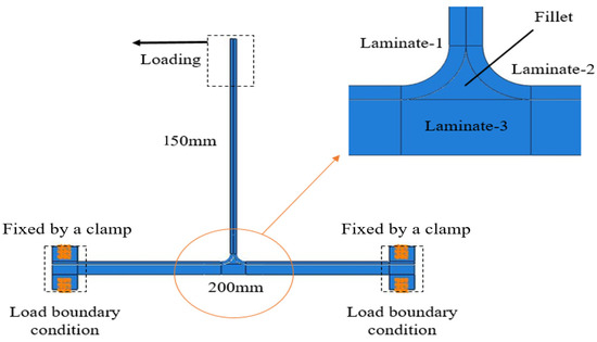
Figure 1.
Geometric model and loading conditions of the composite T-joint.
2.2. Cohesive Zone Modeling
The L-ribs, filling area, and soleplate are connected through adhesive curing. The damage in the composite T-joints under different loadings occurs at the interface and rarely involves damage to the matrix or fibers. Therefore, “Cohesive Zone Modeling” is widely used as a key technique for simulating the mechanical behavior of the cohesion zone in numerical models. The CZM requires placing a layer of cohesive elements on the expected layered path. When the load increases to the critical point, the element begins to fail. The element fails completely when the stiffness decreases to 0, and thus indicates the initiation and propagation of cracks. To determine the failure mode of cohesive elements, their force–displacement relationship under bending load must be defined, i.e., the constitutive equation of damage initiation and evolution. Four models are commonly used for the constitutive equations used in the CZM, namely bilinear, exponential, logarithmic, and power models [23,24].
For the convenience of analysis, this study uses the bilinear constitutive model (Figure 2), in which σ0 is the strength limit of the material, δ0 is the displacement when the cohesive element reaches the strength limit, δt is the displacement when the cohesive element completely fails, K0 is the initial element stiffness, (1 − D) × K0 defines the stiffness of the element containing damage, and GC is the energy release rate of the cohesive element during the failure process. The cohesive element is linear before damage, and the stress linearly increases with the increase in the displacement of the element. When the stress of the element reaches the limit, the stiffness begins to decrease, the element begins to experience damage, and the load bearing capacity of the material declines [25].
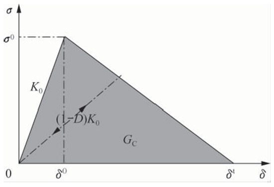
Figure 2.
Bilinear cohesive zone constitutive model.
The method for defining the contact proper ties of the cohesive behavior is the same as the method for defining cohesive materials. The nominal separation force of the contact point in the 3D problem consists of three components: tn, which denotes the 3D normal component, and ts and tt, which represent the two shear components. The deformations of these components are εn, εs, and εt, respectively. In accordance with elasticity,
where K is the stiffness matrix.
When the separation force in the contact surface satisfies the damage initiation criterion for strength, the contact stiffness of a certain contact point begins to degenerate, and damage starts to occur. The damage initiation criterion adopted in this study is the second nominal stress strength, whereas the damage evolution criterion adopts the hybrid energy release rate criterion.
- (1)
- Strength criterion
To accurately simulate the initiation of interface damage under complex stress, the second nominal stress strength criterion is adopted for the FE analysis.
where ,, and are the respective maximum stress values of the terms.
- (2)
- Energy release rate criterion
The critical strain energy release rate is an important parameter in the characterization of the interlaminar fracture toughness of composite laminates. Cracks have three main types: open, slide open, and staggered types. The evolution criterion for evaluating the damage expansion is relatively independent of the initial criterion for assessing the damage. The former is mathematically defined as
The different modes of fracture energy are expressed as f(Gi). Various expressions are often used in the literature to make the simulation results consistent with the real situation. In the FE analysis, a semi-empirical damage extension criterion, which is called Benzeggagh–Kenane criterion, is used to accurately match the test results in many cases.
2.3. Mesh
The composite T-joint is meshed with eight-node shell elements (S8R) due to a balance between computational accuracy and efficiency. The arc area is densely meshed, whereas the other areas are divided by a coarse mesh. A layer of cohesive elements is laid on the laminate interface. Based on the observation of the failure mode of the specimens, the laminate is prone to failure near the bonding interface. To accurately simulate the failure of composite T-joints, cohesive elements are inserted between the layers close to the bonding interface of the laminate.
The mesh density of the cohesive zone is determined by the size of the damage process area. The basic principle is that the number of cohesive zone elements in this area cannot be less than 3–5. The details of this principle can be found in the work of Turon et al. [26]. In the present study, we conducted a mesh-independent analysis for the composite T-joint. We have taken a relatively balanced point between computational accuracy and computational efficiency, and therefore the mesh size of cohesive elements in the arc area is set to 0.25 mm, which satisfies the above requirements. The numerical model has 62,678 elements, including 42,300 eight-node shell elements (S8R) and 20,378 cohesive elements.
2.4. Material Parameters
The parameters of the composite material used in this study (i.e., T700/QY8911, formed by resin transfer molding (RTM) process, and the fiber volume fraction is about 60%) are listed in Table 1 [27], provided by the “AVIC COMPOSITE CORPORATION LTD”. The radius of the filler region is 5 mm. The parameters that characterize damage initiation and delamination expansion include cohesive strength and critical energy release rate [28]. The critical strain energy release rate of the matrix can be measured through standard fracture toughness experiments (Table 2). The resin matrix used in this study is QY8911. As shown in Table 2 [27], and are the ultimate strengths along the n (stretching direction) and t and s directions (shear directions), respectively, and GIC/GIIC is the cohesive element type I/II energy release rate.

Table 1.
Mechanical properties of T700/QY8911 [27].

Table 2.
Mechanical properties of the cohesive element [27].
The most critical parameter of the cohesive zone technology is the fracture toughness. The strength value has no significant effect on the calculation results. With regard to the strength of the cohesive elements, many studies obtained the appropriate cohesive strength value by comparing the numerical results with experimental data [29,30]. Turon et al. [26] established a formula for deriving the interface strength value based on the required mesh size and the actual interface toughness value. Studies showed that the ultimate strength value of the cohesive elements is within a certain range, and this value exerts minimal effect on the calculation results. A related study [31] suggested that a higher intensity value leads to smaller damage process area, which in turn requires denser mesh and a higher computational cost. By contrast, coarse grids can be used to reduce the calculation costs while ensuring the calculation accuracy of low strength values. In addition, no recognized, accurate, and easy-to-operate experimental method for determining the interface strength value is available. The mechanical parameters of the cohesive element are measured by tensile, compression, and shear experiments with respect to interlamination on the same type of laminates. Based on these, the parameters are modified by combining the finite element model and relevant experiment results. The mechanical properties of the cohesive elements used in this study are summarized in Table 2 [27].
2.5. Verification
To verify the FE model established in this work, a quasi-static tensile experiment is performed.
2.5.1. Test Setup
The fixture is presented in Figure 3. The material of the reinforcing sheet of the specimen is glass fiber reinforced plastic. The tensile test was conducted on a MTS810 testing machine, and the loading speed is set to 2 mm/min. Before the formal experiment, test debugging is performed to eliminate gaps and check whether the loading and recording systems are in normal state. The maximum load of the pre-test cannot exceed 30% of the design load. During the formal test, the specimens are continuously loaded until failure, and the failure mode and load are recorded [32]. The strain signal is collected using the DH3816 data collection system, and the frequency gap is 20 Hz. The test system is depicted in Figure 4. Regarding the experimental verification, three specimens were used to exclude the influence of material error and systematic error between different specimens.
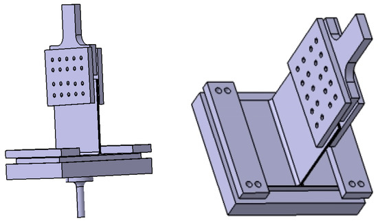
Figure 3.
Schematic of the fixture.
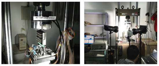
Figure 4.
Test system diagram.
2.5.2. Comparative Analysis
As shown in Figure 5, the interface between the filler and the L-ribs under tensile load initially demonstrates delamination. As the load increases, this failure mode gradually expands to both sides until it reaches a certain level and causes the final failure. The deformation of specimen is not obvious in the loading process, and the failure is always instantaneous. Figure 5 records the shape of the failure when the load displacement curve of the specimen begins to plunge. The numerical simulation results are consistent with the experimental results, and the mechanical behavior of the composite T-joints can be accurately simulated under tensile load.

Figure 5.
Comparison of the failure modes: (a) Numerical result; (b) Experimental result.
Figure 6 shows the loading and unloading load-strain curves of the specimens during pretension. The pretension is supposed to eliminate the internal gap of the composite T-joint, offset the pre-tightening force during the fixture installation process, loading, and unloading during the elastic stage of the specimens. It is not difficult to see from Figure 6 that the curves at the corresponding points are in good agreement, laying the foundation for the subsequent tensile failure experiments.
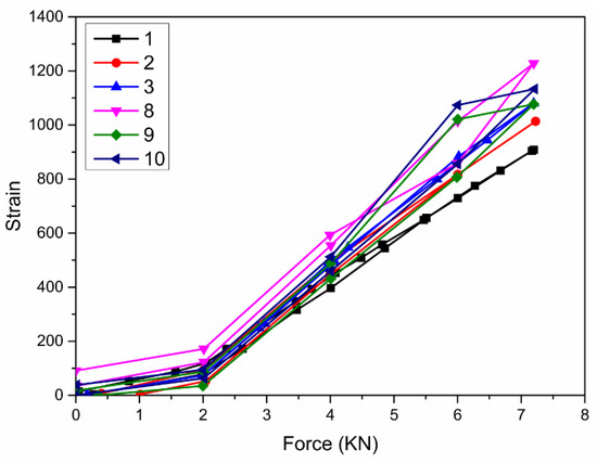
Figure 6.
Load-strain curves of loading and unloading of specimens during pretension.
A comparison between the numerical simulation and experimental results of the load–displacement curves of composite T-joints under tensile load is illustrated in Figure 7. The experimental and numerical load displacement curves can be roughly described in the following three stages: elastic stage, plastic stage, and failure stage. “Elastic stage” refers to the stage where the slope of the load displacement curve of the specimen is roughly unchanged. In this stage, the specimen is within the elastic range without plastic deformation, and the variation of displacement accounts for about 65% of the failure displacement. “Plastic stage” refers to that the slope of the load displacement curve of the specimen begins to decline slowly. At this stage, plastic deformation begins to occur, and micro-cracks are constantly generated and expanded inside the specimen. The variation of displacement at this stage accounts for approximately 30% of the failure displacement. The load bearing capacity and failure displacement of the joints are in good agreement with the experimental results, it shows that the model established in this study can accurately and effectively simulate the mechanical behavior of composite T-joints under tensile load. The load–displacement curve is affected by the large-area failure of the cohesive element inserted in the interface before the failure of the T-joint, resulting in a small fluctuation in the load–displacement curve, as shown in Figure 7.
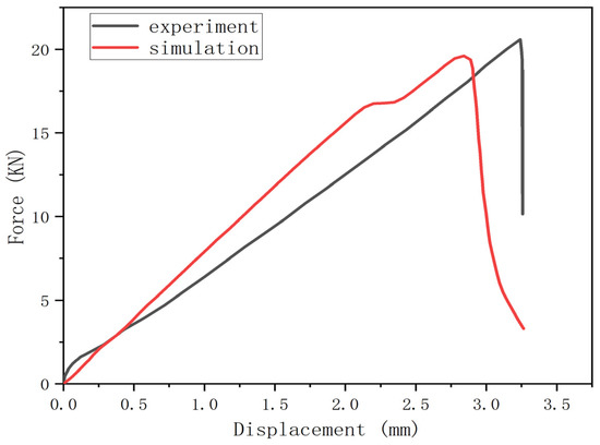
Figure 7.
Comparison of the load displacement curves obtained through numerical simulation and experiment.
The slope of the simulation curve is slightly different from that of the test curve. This discrepancy can be ascribed to the tiny defects in the real structure; such defects reduce the incorporate stiffness of the structure at the initial stage of tension. The slope of the load–displacement curve is low, but it has no obvious influence on the failure load. Moreover, the existence of tiny defects cannot be simulated in numerical simulation. Meanwhile, the failure of T-joint of composite materials is very fast, and almost no visible plastic deformation is generated. However, in the simulation, due to the influence of element mesh and stress concentration, plastic deformation of some elements will lead to the small reduction in the load-displacement curve, resulting in the difference between numerical and experimental curves.
3. Definition of the Defects in Composite T-Joints
Internal defects are inevitable due to the technology used in the manufacturing process of T-joints. On the basis of the verification of the proposed FE model in the previous section, this section analyzes the influence of three different defects, namely core material defects, floating defect of the radius of the filling area, and debonding defects in the interface between the L-ribs and the filling area, on the load bearing capacity of composite T-joints.
- Considering the limitation of the production process, the core materials in the actual structure are bonded together by two sections. This procedure results in core material fracture defects. The positions of the core material defect L1 are at 40, 80, 120, and 150 mm (Figure 8).
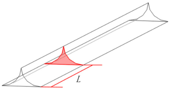 Figure 8. Core material defect.
 - The influence of the co-curing process of the filling area causes the corresponding radius to have a certain floating change. The radii R are set to 4, 5, and 6 mm (Figure 9).
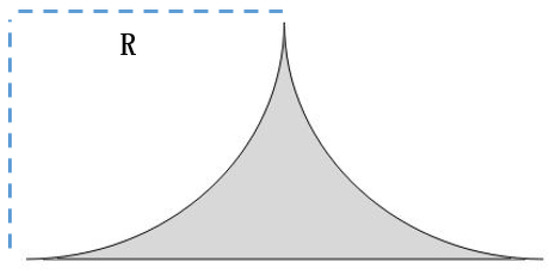 Figure 9. Radius floating defect.
 - The debonding defects between the L-ribs and the filling area caused by the co-curing process are shown in Figure 10. The debonding defects are always on the side of the joint. The debonding defect lengths L2 are 10, 14, 18, 30, 50, 70, and 120 mm.
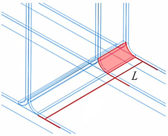 Figure 10. Debonding defect.
To compare and analyze the influence of different defects on the bending failure mode and load bearing capacity of T-joints, four groups of specimens (A, B, C, and D) are selected for the numerical simulation under bending load (Table 3).

Table 3.
Four groups of composite T-joint samples.
4. Results and Discussion
4.1. Failure Mode
The failure modes of experiment and simulation are in good agreement and no obvious difference is observed in the failure mode of the composite T-joint due to the three defects. Figure 11 is the experimental picture in the published paper [33]. The size and loading process of the specimen in the literature are similar to that in this paper, aiming to compare with the failure modes obtained by numerical simulation. As shown in Figure 11 and Figure 12, the interface between the filling area and the L-rib displays delamination under bending load. With the continuous increase of load, this failure mode gradually expands to both sides until it reaches a certain extent and causes the final failure of the T-joints. The delamination process can be divided into three stages.
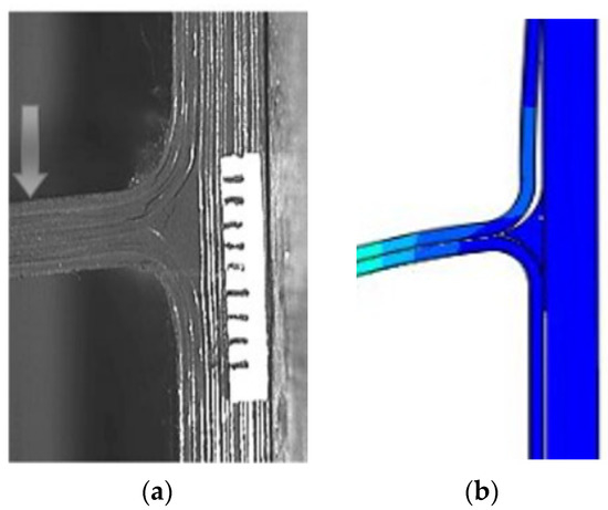
Figure 11.
Failure mode of composite T-joint under bending load: (a) experimental failure mode [33]; (b) simulated failure mode.
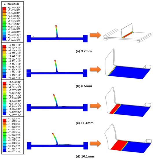
Figure 12.
Damage propagation in the composite T-joint under bending load: (a) 3.7 mm, (b) 6.5 mm, (c) 11.4 mm, (d) 16.1 mm.
Linear elastic stage: The model exhibits no damage from the beginning of loading to the occurrence of cracks. This behavior is within the elastic range. The load increases linearly with the increase of the displacement. During this process, the displacement is caused by the bending of the L-ribs, and the model is at a low stress level (Figure 12a). In this stage, the specimen is within the elastic range without plastic deformation, and the variation of displacement accounts for approximately 65% of the failure displacement.
Damage initiation and propagation stage: Delamination occurs at the interface between the arc area and the L-rib, and the crack expands to both sides. The damage expansion is relatively slow, and the overall structural rigidity gradually decreases during the expansion process (Figure 12b). “Damage initiation and propagation stage” is equal to “plastic stage”, when the slope of the load displacement curve of the specimen begins to decline slowly. At this stage, plastic deformation begins to occur, and micro-cracks are constantly generated and expanded inside the specimen. The variation of displacement at this stage accounts for about 30% of the failure displacement.
Rapid failure stage: As the increase of load, the debonding failure extends to the entire L-rib. When the damage reaches the interface between the L-rib and the soleplate, the damage propagation speed becomes significantly faster until the T-joint fails completely (Figure 12c,d). The failure of specimen is not evident in the loading process, and the failure is always instantaneous. The variation of displacement at this stage accounts for approximately 5% of the failure displacement.
4.2. Influence of Three Different Defects on the Load Bearing Capacity
4.2.1. Core Material Defects
In consideration of the cross-section of the filling area, the actual manufacturing process adopts the bonding method at the interrupted surface. In the FE model, the cohesive contact is used to simulate the bonding interface at the cross-section, and the distance between this section and the boundary when L1 is 40, 80, 120, and 150 mm is calculated through numerical simulation. The load displacement curves under bending load are displayed in Figure 13.
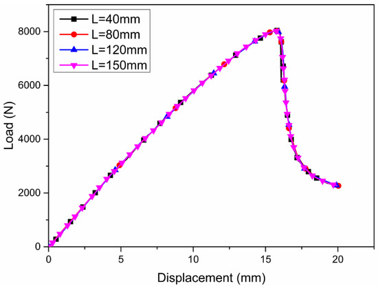
Figure 13.
Load–displacement curves of the T-joints due to core material defects at different positions.
The comparison of the load–displacement curves indicates that the cross-sectional defects in the core material exhibit a slight effect on the overall mechanical properties of the composite T-joint under bending load. The four load–displacement curves almost overlap. During the loading process, the L-ribs/fillet interface and the L-ribs/soleplate interface mainly bear the loading, and this is also the area where the microcrack is first generated and propagated. The external load will not cause damage to the bonding interface at the core material section because the direction of the former is parallel to that of the cross section of the core material. The core material deformation at both ends of the section remains consistent. Therefore, the existence of interruption surface defects in the core material has almost no effect on the mechanical behavior of composite T-joints. However, if the defects in the core material are not perpendicular to the section, but at a certain angle to the section, or there are more than two core material defects with different angles at the same time, it may have a great impact on the bearing capacity of the composite T-joint under bending load, which is also the subject of further research.
4.2.2. Radius Floating of the Fillet
In the actual manufacturing process of composite T-joints, the radius of the fillet exhibits certain degree of deviation due to the application of co-curing and integral molding technologies. This section discusses the radius floating of the fillet when R is 4, 5, and 6 mm. The load–displacement curves of the composite T-joints under bending load are shown in Figure 14.
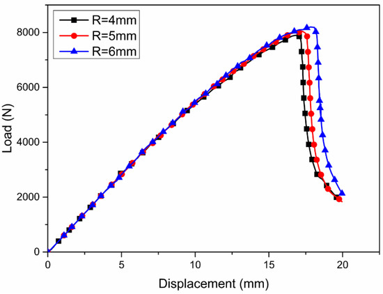
Figure 14.
Load–displacement curves of the T-joints with different radius floating defects.
In general, the floating of the radius floating of the fillet within a certain range does not significantly reduce the bearing capacity of the composite T-joint under bending loading. During the bending loading of composite T-joints, the filling area serves as the stress concentration area. Increasing the radius of the filling area can effectively reduce the stress level in the arc area of the composite T-joint. More importantly, it can increase the bonding area between the fillet/L-ribs interface and fillet/soleplate interface to improve the structural bearing capacity. Therefore, the structural design should consider the weight gain of the structure and other factors, and a large filling area radius should be selected.
4.2.3. Debonding Defects
To investigate the debonding defects with different sizes in the arc area, the influence of different defect lengths (10, 14, 18, 30, 50, 70, and 120 mm) on the load bearing capacity of the composite T-joint is studied. Figure 15 depicts the load–displacement curves of composite T-joints with different debonding defects with different lengths in the arc area under bending load. As shown in the figure, the load bearing capacity of the composite T-joint gradually decreases as the length of the debonding defect in the arc area increases. As the debonding defect of fillet/L-ribs interface increases, the bonding area of the fillet/L-ribs interface decreases, so the bearing capacity of the fillet/L-ribs interface becomes weaker and weaker in the bearing process. Once complete debonding failure occurs, the L-ribs/soleplate interface will bear additional tensile and shear loading, aggravating the failure of the overall structure. Moreover, due to the introduction of such defects, the overall stiffness of the structure decreases, and the stiffness of the load–displacement curves tends to decline in the initial stage. Compared with the debonding defect with a length of 10 mm, due to the debonding defect with a length of 120 mm, the failure load of composite T-joints decreased from 8120 N to 6230 N, which is equivalent to a 23.8% reduction in the load.
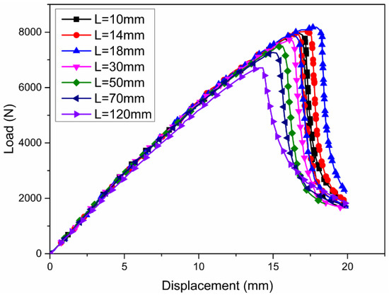
Figure 15.
Load–displacement curves of T-joints with different lengths of debonding defects.
4.3. Influence of Combined Defects on the Load Bearing Capacity
4.3.1. Orthogonal Experiment Method
Various types of defects simultaneously occur because of the processing technology and service environment of composite T-joints. As a result, a coupling effect on the load bearing capacity and mechanical properties of the structure exists. Therefore, the effects of combined defects on the load bearing capacity of composite T-joints should be clarified. The analyses for single- or two-factor experiments are relatively simple due to the small number of factors. However, actual scenarios require the simultaneous investigation of three or more experimental factors. The scale of a comprehensive experiment is extremely large, and implementing such a test is difficult due to the limitations of the experimental conditions. The orthogonal experiment method is a high-efficiency experimental design approach that selects several representative combinations from the overall experiment to obtain the optimal level of combination.
In the experimental arrangement, selecting several levels for each factor within the scope of the study is equivalent to placing a grid in the selection area. The orthogonal design requires the selection of a representative part of the test points from the comprehensive test table of the optimal area to conduct the test. The nine “.” marked with test numbers in Figure 16 represent the nine points selected from the 27 test points based on the orthogonal table L9 (34). The test arrangements of the two test schemes are summarized in Table 4.
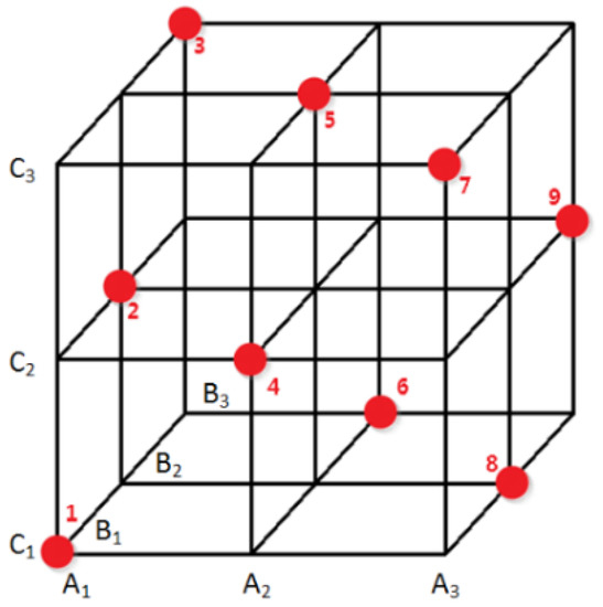
Figure 16.
Test point in the orthogonal test.

Table 4.
Comparison of the two test schemes.
4.3.2. Combined Defect Analysis
- (1)
- Determination of the Factor Level
Taking the composite T-joint in this study as an example, three different types of defects, including the core material defect position L1, the radius R of the filling area, and the debonding defect length L2 of the interface between the L-rib and filling area, are selected as the design parameters. The orthogonal experiment method and numerical simulation are combined to study the effect of combined defects on the load bearing capacity of composite T-joints. The test factors and levels selected for the former are shown in Table 5. Three factors with three levels each are selected. Therefore, the orthogonal table L9 (34) satisfies the requirements.

Table 5.
Test factors and levels.
- (2)
- Orthogonal Test Calculation Results
Using finite element analysis software ABAQUS, the nine combinations given in Table 4 are numerically simulated and analyzed. Factor codes A, B, and C represent L1, R, and L2, respectively. The values of k and R in the orthogonal table are calculated using the following equations, and the results are summarized in Table 6.

Table 6.
Results of the orthogonal test.
The results of the orthogonal experiment indicate that the core material defects, the radius of the filling area, and the debonding defect in the arc area have different sensitivities to the load bearing capacity of composite T-joints. The debonding defect has the highest sensitivity, followed by the radius of the filling area and then the core material defect. Moreover, the core material defect is hardly related to the load bearing capacity of the T-joint, whereas the radius of the filling area is positively correlated with the latter. The debonding defects are negatively correlated with the load bearing capacity of the T-joint. The optimal combination of the three defects is as follows: L1 = 40 mm, R = 6 mm, L2 = 10 mm.
The T-joints load–displacement curves with combined defects are shown in Figure 17, and the ultimate loads of these joints are listed in Table 7. The effect of single core material defect on the bearing capacity of composite T-joint under bending load is very limited. The floating error of fillet radius within a certain extent also has little influence on the bearing capacity of T-joint. The significant and non-negligible defect is the debonding defect at the of fillet/L-ribs interface, which has greatly reduced the bending bearing capacity of the T-joint when it exists alone. More importantly, the findings reveal that the combined defects have a coupling effect on the load bearing capacity of the T-joint. This phenomenon occurs because different defects aggravate the stress concentration in the filling area and its vicinity, and thus greatly affects the load bearing capacity of composite T-joints.
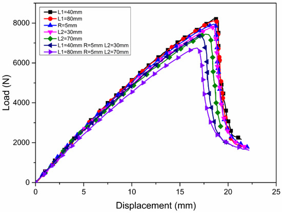
Figure 17.
Load–displacement curves of T-joints with combined defects.

Table 7.
Ultimate loads of T-joints with combined defects.
5. Conclusions
This study establishes an efficient and accurate numerical model and analyzes the effect of different kinds of defects on the load bearing capacity of composite T-joints under bending load. The conclusions obtained from the results are enumerated below.
- The FE model of the composite T-joint is established, and the cohesive element is used to simulate the interface delamination failure. The experimental results verify the calculation results of the numerical model, and it is found that predicted failure area, failure displacements, and failure load have good correlation with the experimental results. The failure modes of the joints with different detects under bending loadings demonstrate delamination at the interface between the filling area and L-rib, which then expands to both sides. One can observe that the failure is a brittle failure with almost no plastic extension of damage.
- The effect of core material defects and radius floating of the fillet on the load bearing capacity of T-joints is negligible to a certain extent due to the factors of composite material manufacturing process. As for the length of the debonding defect in the fillet/L-ribs interface, the influence on the bending bearing capacity of the structure is very obvious. In particular, the ultimate load of the 120 mm defect is reduced by roughly 25%, compared with the 10 mm defect.
- The orthogonal experiment method is adopted to study the defect sensitivity and the influence of combined defects on the load bearing capacity of T-joints. The results show that the three kinds of defects have different sensitivities, and the sensitivities are sorted, which provides theoretical guidance for the damage detection and maintenance of composite T-joints. More importantly, an original discovery is that the combined defects have a coupling effect on the bearing capacity, and the coexistence of multiple defects is a more severe test for the bearing capacity of T-joints.
Author Contributions
Conceptualization, G.L., F.X. and Y.C.; methodology, G.L.; software, G.L.; validation, G.L.; formal analysis, G.L.; investigation, G.L.; resources, C.C.; data curation, J.L.; writing—original draft preparation, G.L.; writing—review and editing, Y.X.; supervision, F.X. and Y.C.; project administration, F.X. and Y.C.; funding acquisition, G.L. and Y.C. All authors have read and agreed to the published version of the manuscript.
Funding
This research was funded by Natural Science Foundation of Shaanxi Province (2021JQ-220).
Institutional Review Board Statement
Not applicable.
Informed Consent Statement
Not applicable.
Data Availability Statement
Publicly available testing data available in this publication.
Conflicts of Interest
The authors declare no conflict of interest.
References
- Dong, P.; Zhao, L.; Huang, H.; Liang, X.; Cao, Z. Research status of composite T-joint structure. Aviat. Manuf. Technol. 2007, Z1, 65–69. [Google Scholar] [CrossRef]
- Hai, L.; Luo, J.; Yang, L.; Ban, H. Experimental study on monotonic and cyclic behaviour of deconstructable beam-to-column composite joints. Eng. Struct. 2022, 272, 114990. [Google Scholar] [CrossRef]
- Feng, W.; He, P.; Pavlovic, M. Combined DIC and FEA method for analysing debonding crack propagation in fatigue experiments on wrapped composite joints. Compos. Struct. 2022, 297, 115977. [Google Scholar] [CrossRef]
- Luo, C.; Wang, S.; Li, W.; Zhang, L.; Pan, L. Mechanical properties of composite T-joints subjected to laser ablation. Compos. Struct. 2022, 294, 115791. [Google Scholar] [CrossRef]
- Mohan, D.G.; Gopi, S. Optimized Parameters Prediction for Single-Pass Friction Stir Welding on Dissimilar Aluminium Alloys T-Joint. Int. J. Emerg. Technol. 2021, 12, 15–20. [Google Scholar]
- Stickler, P.B.; Ramulu, M. Experimental study of composite T-joints under tensile and shear loading. Adv. Compos. Mater. 2006, 15, 193–210. [Google Scholar] [CrossRef]
- Ahmadi, S.; Zeinedini, A. Experimental, theoretical and numerical investigation of the drilling effects on mode I delamination of laminated composites. Aerosp. Sci. Technol. 2020, 104, 105992. [Google Scholar] [CrossRef]
- Li, H.C.H.; Dharmawan, F.; Herszberg, I.; John, S. Fracture behaviour of composite maritime T-joints. Compos. Struct. 2006, 75, 339–350. [Google Scholar] [CrossRef]
- Herszberg, I.; Li, H.; Dharmawan, F.; Mouritz, A.; Nguyen, M.; Bayandor, J. Damage assessment and monitoring of composite ship joints. Compos. Struct. 2005, 67, 205–216. [Google Scholar] [CrossRef]
- Dharmawan, F.; Thomson, R.S.; Li, H.; Herszberg, I.; Gellert, E. Geometry and damage effects in a composite marine T-joint. Compos. Struct. 2004, 66, 181–187. [Google Scholar] [CrossRef]
- Dharmawan, F.; Li, H.; Herszberg, I.; John, S. Applicability of the crack tip element analysis for damage prediction of composite T-joints. Compos. Struct. 2008, 86, 61–68. [Google Scholar] [CrossRef]
- Chen, J.; Ravey, E.; Hallett, S.; Wisnom, M.; Grassi, M. Prediction of delamination in braided composite T-piece specimens. Compos. Sci. Technol. 2009, 69, 2363–2367. [Google Scholar] [CrossRef]
- Hélénon, F.; Wisnom, M.R.; Hallett, S.R.; Trask, R.S. Investigation into failure of laminated composite T-piece specimens under bending loading. Compos. Part A Appl. Sci. Manuf. 2013, 54, 182–189. [Google Scholar] [CrossRef]
- Hélénon, F.; Wisnom, M.; Hallett, S.; Trask, R. Numerical investigation into failure of laminated composite T-piece specimens under tensile loading. Compos. Part A Appl. Sci. Manuf. 2012, 43, 1017–1027. [Google Scholar] [CrossRef]
- Trask, R.S.; Hallett, S.R.; Helenon, F.M.M.; Wisnom, M.R. Influence of process induced defects on the failure of composite T-joint specimens. Compos. Part A Appl. Sci. Manuf. 2012, 43, 748–757. [Google Scholar] [CrossRef]
- Zhu, L.; Cui, H.; Li, Y.; Sun, W. Numerical analysis of failure of composite T-joint with defects. Acta Aeronaut. Sin. 2012, 33, 287–296. [Google Scholar]
- Barzegar, M.; Moallem, M.D.; Mokhtari, M. Progressive damage analysis of an adhesively bonded composite T-joint under bending, considering micro-scale effects of fiber volume fraction of adherends. Compos. Struct. 2020, 258, 113374. [Google Scholar] [CrossRef]
- Cartie, D.D.; Dell’Anno, G.; Poulin, E.; Partridge, I.K. 3D reinforcement of stiffener-to-skin T-joints by Z-pinning and tufting. Eng. Fract. Mech. 2006, 73, 2532–2540. [Google Scholar] [CrossRef]
- Budhe, S.; Banea, M.; de Barros, S.; da Silva, L. An updated review of adhesively bonded joints in composite materials. Int. J. Adhes. Adhes. 2016, 72, 30–42. [Google Scholar] [CrossRef]
- Zhou, D.W.; Louca, L.A.; Saunders, M. Numerical simulation of sandwich T-joints under dynamic loading. Compos. Part B 2008, 39, 973–985. [Google Scholar] [CrossRef]
- Carneiro, M.A.S.; Campilho, R.D.S.G. Analysis of adhesively-bonded T-joints by experimentation and cohesive zone models. J. Adhes. Sci. Technol. 2017, 31, 1998–2014. [Google Scholar] [CrossRef]
- Blake, J.I.R.; Shenoi, R.A.; House, J.; Turton, T. Progressive damage analysis of tee joints with viscoelastic inserts. Compos. Part A Appl. Sci. Manuf. 2001, 32, 641–653. [Google Scholar] [CrossRef]
- Wagner, W.; Balzani, C. Simulation of delamination in stringer stiffened fiber-reinforced composite shells. Comput. Struct. 2008, 86, 930–939. [Google Scholar] [CrossRef]
- Alfano, G. On the influence of the shape of the interface law on the application of cohesive-zone models. Compos. Sci. Technol. 2006, 66, 723–730. [Google Scholar] [CrossRef]
- Cui, H.; Li, Y.; Liu, Y.; Guo, J.; Xu, Q. Numerical simulation of the failure of composite joints with filled areas based on the cohesive zone model. J. Compos. Mater. 2010, 27, 161–168. [Google Scholar]
- Turon, A.; Davila, C.G.; Camanho, P.P.; Costa, J. An engineering solution for mesh size effects in the simulation of delamination using cohesive zone models. Eng. Fract. Mech. 2007, 74, 1665–1682. [Google Scholar] [CrossRef]
- Li, G.; Xue, P.; Luo, G.; Yu, Z.; Yang, J.; Tu, B. Shear behavior and failure analysis of a composite T-joint with a cutout. J. Compos. Mater. 2015, 49, 2307–2315. [Google Scholar] [CrossRef]
- Chen, P.; Chai, Y. Cohesive zone model for failure analysis of integral composite structure. J. Nanjing Univ. Aeronaut. Astronaut. 2008, 40, 442–446. [Google Scholar]
- Parmigiani, J.P.; Thouless, M.D. The effects of cohesive strength and toughness on mixed-mode delamination of beam-like geometries. Eng. Fract. Mech. 2007, 74, 2675–2699. [Google Scholar] [CrossRef]
- Li, S.; Thouless, M.D.; Waas, A.M.; Schroeder, J.A.; Zavattieri, P.D. Use of mode-I cohesive-zone models to describe the fracture of an adhesively-bonded polymer-matrix composite. Compos. Sci. Technol. 2005, 65, 281–293. [Google Scholar] [CrossRef]
- Alfano, G.; Crisfield, M.A. Finite element interface models for the delamination analysis of laminated composites: Mechanical and computational issues. Int. J. Numer. Methods Eng. 2001, 50, 1701–1736. [Google Scholar] [CrossRef]
- Standard Practice for Tensile Properties of Tapered and Stepped Joints of Polymer Matrix Composite Laminates. Available online: https://www.astm.org/d8131_d8131m-17e01.html (accessed on 8 November 2022).
- Wu, H.; Xiao, J.; Xing, S.; Wen, S.; Yang, F.; Yang, J. The failure experiment of composite T-joints with induced defects under bending load. J. Natl. Univ. Def. Technol. 2015, 37, 128–136. [Google Scholar]
Publisher’s Note: MDPI stays neutral with regard to jurisdictional claims in published maps and institutional affiliations. |
© 2022 by the authors. Licensee MDPI, Basel, Switzerland. This article is an open access article distributed under the terms and conditions of the Creative Commons Attribution (CC BY) license (https://creativecommons.org/licenses/by/4.0/).