Article

Deterioration of Novel Silver Coated Mirrors on Polycarbonate Used for Concentrated Solar Power

by
Coraquetzali Magdaleno López
1,2,
José de Jesús Pérez Bueno
1,*,
José Antonio Cabello Mendez
1,
Rosalba Hernández Leos
3,
Maria Luisa Mendoza López
4,
Adrián Sosa Domínguez
3 and
Yunny Meas Vong
1
1
Centro de Investigación y Desarrollo Tecnológico en Electroquímica, S. C., Parque Tecnológico Querétaro-Sanfandila, Pedro Escobedo, Queretaro 76703, Mexico
2
Centro de Investigación y de Estudios Avanzados del Instituto Politécnico Nacional, Unidad Saltillo, Av. Industria Metalúrgica No. 1062, Parque Industrial, Ramos Arizpe 25900, Mexico
3
Facultad de Química, Universidad Autónoma de Querétaro, Centro Universitario Cerro de las Campanas, Queretaro 76010, Mexico
4
Tecnológico Nacional de México, Instituto Tecnológico de Querétaro, Av. Tecnológico s/n Esq. M. Escobedo Col. Centro C.P., Querétaro 76000, Mexico
*
Author to whom correspondence should be addressed.
Sustainability 2022, 14(24), 16360; https://doi.org/10.3390/su142416360
Submission received: 13 October 2022 / Revised: 19 November 2022 / Accepted: 30 November 2022 / Published: 7 December 2022
(This article belongs to the Special Issue Renewable Energy Technologies for Sustainable Development)

Abstract

:
The lifetime of mirrors in outdoor conditions is crucial in the correct operation of any concentrating solar power (CSP) installation. In this work, the corrosion behavior of two types of metallized surfaces was studied. The first was made of a flexible polymer having a deposited reflective silver metallic film. The second was made of the same surface type with a dielectric SiO2 protection coating by an atmospheric pressure plasma jet. Polycarbonate sheets were used as substrates on which metallic silver was deposited by the Dynamic Chemical Deposit technique. This electroless technique allowed producing the mirror finishing under environmental conditions by sequentially spraying; as aerosols projected towards the substrate surface, the activation and reducing-oxidizing solutions with rinsing after each one. The silver coatings were about 100 nm thick. Environmental and accelerated weathering degradation and salt and sulfide fogs were carried out. XPS analyses show that the corrosion products formed were Ag2S, AgCl, and Ag2O. It was observed that the tarnishing was initiated locally by the formation of Ag2S columns as eruptions on the surface. Subsequently, the ions diffused through the protective layer and into the silver reflective layer, chemically reacting with the silver. The main atmospheric agents were H2S, chloride particles, and HCl. High reflectance was initially obtained of about 95%. The obtained results suggest mechanisms for the degradation of exposed silver surfaces to moisturized atmospheres with corrosive compounds.

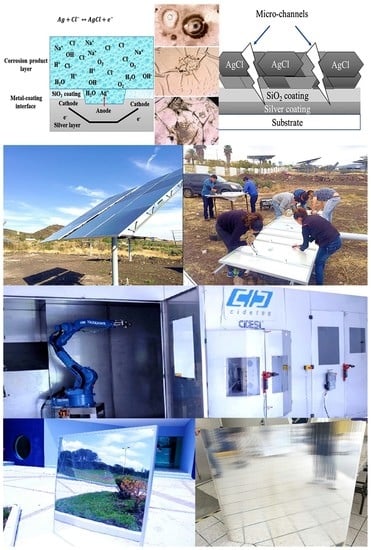
Graphical Abstract

1. Introduction

Concentrating solar power (CSP) is one of the leading technologies for converting energy from the sun into thermal energy and subsequently into electrical energy [1,2,3,4,5]. One of the main components that make up these technologies are solar reflectors, for which durability is one of the crucial factors in the correct operation of any CSP installation. They require satisfying many requirements, including profitability, having a high specular reflectance, and long-term environmental stability [1,2]. However, the performance of the reflectors depends mainly on the films deposited on the substrates [6,7]. Metal films such as silver, copper, and aluminum usually offer adequate performance for optical reflectors [8]. Silver (Ag) has some advantages as a thin film material, since it is considered because of its relatively high ionization potential, because it is a noble metal that has high conductivity, and because it has high reflectance within visible and infrared illumination [9,10,11].
Commercial mirrors are usually second-surface mirrors, meaning the reflective coating is placed on the bottom of a transparent substrate. They have a drawback because the total solar reflectivity is reduced through absorption losses. On the other hand, a first-surface mirror has a reflective layer deposited on the front part of the substrate so that the light is reflected directly on the upper surface [10,12]. The disadvantage of silver as a top coating is that it tarnishes and corrodes with exposure to the atmosphere because of sulfur [13] and chloride [14,15]. Therefore, first-surface silver mirrors require a transparent protective layer or a multilayered coating with high adhesion between each layer and the substrate.
Most published studies that have been conducted in the field of CSP are based on phenomenological approaches. The characterization of degradation, which mainly considers the loss of reflectance, is rarely related to physical or chemical processes responsible for the degradation of properties [16]. The gained experience in CSP plants allows identifying stress factors responsible for solar glass mirror degradation, such as wind, dust, rain, dew, humidity, irradiation, and temperature. Depending on the placement surroundings, the constraints involve sand, saline fog, chemical pollutants from near industries, and so forth [17]. The modeling of humidity has been approached using empirical models, such as the Eyring-based model, Peck’s model, and the Temperature (°C) + Relative Humidity (%) correlation (T + RH) [16].
The weathering degradation of solar mirrors is usually related to their specular reflectance’s decrement [18,19,20,21,22]. There are reports on mirror deterioration in environmental conditions, but mostly of glass substrates [17]. In the case of polymeric substrates, the deposition techniques are under vacuum conditions [23].
Considering that both silver and aluminum are prone to change their oxidation state, altering the surface specularity, several schemes have been developed to protect mirrors from corrosion during long-term environmental exposure [24,25,26,27,28]. These schemes frequently incorporate one or more coatings of protection in combination with a thin deposit for adhesion that holds them attached to the metallic layer.
The main environmental corrosion products of silver are silver sulfide (Ag2S) and silver chloride (AgCl), although silver oxide (Ag2O) and silver sulfate (Ag2SO4) also have been found [27,28,29,30]. These corrosion products result from electrochemical reactions of silver when exposed to small amounts of air pollutants in the environment. In addition, there is a synergistic effect of multiple contaminants, particularly in the presence of oxygen and moisture, which accelerates corrosion [15]. It is of particular interest to understand the possible corrosive degradation mechanisms and the sub-products formed in the metallic layers of the solar mirrors and develop methods and strategies to prevent such undesired changes in the future.
Accelerated aging techniques are commonly used to correlate the effects of laboratory tests and outdoor exposure. However, these mechanisms are irreversible, so many studies focus on classifying better materials and addressing different aspects, such as composition, environmental conditions, and the structure of mirrors, among others.
Limam et al. [31] studied the formation of channels that connect the surroundings of the silver layer, through the protective layer, with the surface pores, which allows the entry of H2S and the growth of columns, causing surface tarnishing. Mishra et al. [32] investigated the behavior of multilayer degradation concerning reflectance in conditions of accelerated weathering degradation and low salt fog. These coatings showed higher reflectance and less deterioration in the accelerated weathering degradation and the salt fog environment. Garcia-Segura et al. [33] studied the degradation of reflective materials for CSP under accelerated aging tests to study the influence of H2S, where they found different degradation patterns for reflectors.
In this work, we show a layered structure of SiO2/silver/polycarbonate that also could be used in applications such as electromagnetic shielding or electromagnetic interference suppressor, similar to other metacomposites with negative electromagnetic parameters [34,35,36,37,38], which have been used in zero-dimensional nanoparticles, one-dimensional wires, two-dimensional coatings, and three-dimensional composites.
Although coatings can help prevent the corrosion of mirrors, this remains a problem where air or moisture can penetrate protective layers, for example, because of mechanical or chemical damage, manufacturing defects, or loss of adhesion. This work aims to evaluate the phenomenon of degradation of the silver mirror surfaces during natural weathering degradation and accelerated tests in a controlled environment and correlate the physicochemical changes in the surface with the loss of reflectance.
This study and its novelty yield using silver-coated polycarbonates by an aerosol-propelled electroless deposition (dynamical chemical plating, DCP) as mirrors for solar concentration, which were protected by a silica coating deposited using an atmospheric pressure plasma jet (APPJ) that was automated for control in its reproducibility and industrial use. Furthermore, the corrosion was studied in this system, since the silver layer did generate defects in specific spots by external or internal factors. Currently, the mirrors are made of glass with significant differences in cost, weight, shipping and handling, installation requirements, replacement procedure, cleaning, breakage, etc. Additionally, the use of coatings brings advantages and difficulties, but this option allows to have a first-surface mirror with increased reflectivity efficiency compared to putting the silver on the substrate back.

2. Material and Methods

2.1. Deposition of the Metallic Layer

Polycarbonate sheets of 10 × 10 cm were used as a substrate on which metallic silver was deposited by the Dynamic Chemical Plating (DCP) technique with a coating thickness of approximately 100 nm. DCP has been used within automatized facilities (Figure 1). The importance of quality control for the layers of the mirror is emphasized. The automated facilities allowed the fabrication and reproducibility of mirrors in big areas, such as 1.2 m × 1.2 m × 0.0015 m of mirrors for heliostats and 1.2 m × 2.4 m × 0.006 m in the case of mirrors for parabolic trough solar concentrators. The surfaces were cleaned and pre-treated with a flame to improve adhesion between the metal layer and the substrate. The surface treatment with a flame was conducted to insert functional groups on the surface as an alternative, similar to corona electrical arc discharges and plasma surface pre-treatments. This was applied to all the pieces until homogenous wettability was obtained. This was conducted in the central section of the facilities shown in Figure 1.

2.2. Deposition of the Protective Layer

After the metallic layer deposition, two different coatings were deposited. For weathering degradation tests, a protective coating consisting of SiO2 was applied. It was carried out by depositing hexamethyl disiloxane (HMDSO) reagent grade ≥98% Sigma-Aldrich brand by the atmospheric pressure plasma jet (APPJ) technique [39,40,41,42,43]. Three applications were put on the metal substrate, allowing a coating thickness of about 600 nm. The process scheme for elaborating the substrate-silver-coating system is shown in Figure 2.
In the case of electrochemical measurements, a protective layer of SiO2 was applied [44,45]. It was deposited by the projection of an ultrasonic fog of tetraethyl orthosilicate (TEOS), reagent grade ≥98% SIGMA-ALDRICH brand (San Luis, MO, USA), to the plasma zone of the APPJ.
The ultrasonic fog was obtained with a Yue-Hua brand ultrasonic nebulizer, model WH-2000. The distance between the plasma jet and the surface was 2 cm, and the time of exposition was 60 s with the projection to the plasma zone of the ultrasonic fog of TEOS. The coating thickness obtained was about 600 nm.
This type of coating has the characteristic of being continuous, homogeneous, dense, and adherent. The purpose of this layer was to serve as a physical barrier to the delay of corrosion. The process scheme for elaborating the substrate-silver-coating system is shown in Figure 2.

2.3. Weathering Degradation Tests

Samples of first-surface solar reflectors with and without protective coatings were tested after exposure to the environment for six months. Figure 3 shows the installed pieces on heliostats. Figure 3a shows the heliostat with sixteen sheets of mirrors and automatic sun-tracking. Figure 3b shows the assembling of mirror sheets with their aluminum frame on a steel structure.
Three replicas were used to guarantee representative test results. Some different parameters were recorded to monitor the conditions of natural exposure, which are important to influence the degradation of the coating and the substrate: temperature, wet weather (the time with condensed water on the surface of the coating), the total energy of solar radiation, and pollutants’ content in the atmosphere (Cl, S, O, N, etc.). Table 1 shows the parameters of the conditions at the place where samples were installed, located at 20°41′51″ N, 100°26′23″ W with an altitude of 1895 m. As reported in the literature, a cross-shaped cut was made on each piece, penetrating the protective and reflective layers and exposing the metal directly to the corrosive atmosphere [33,46].
The behaviors of similar samples subjected to a series of accelerated aging tests based on salt fog and sulfur at high relative humidity were examined. The tests in a fog chamber were performed for 96 h under ASTM B117 [47]. Comparative studies were conducted on coated samples in a test atmosphere with controlled concentrations of 0.1 M H2SO4 [25] and 5% NaCl [47] at 28 °C and approximately 75% RH. Samples introduced into this test atmosphere fogged after 24 h of exposure. Subsequently, the morphology, structure, and chemical changes on the surfaces were evaluated.

2.4. Electrochemical Measurements

The samples with metallic coating and a barrier layer of SiO2 by TEOS were electrochemically tested. The tests were conducted using H2SO4 because of predisposition of silver to oxidize in environments with hydrogen sulfide (H2S) [48] and 0.5 M as the electrolyte, which was bubbled with nitrogen to remove the oxygen. The reference electrode used was SCE and platinum was the counter electrode. EIS measurements were performed at open circuit potential (OCP), with an amplitude of 10 mV and a frequency of 105 to 0.01 Hz.
Cyclic potentiodynamic polarization (CPP) measurements were studied at 10 mV/s from −0.3 V vs. OCP to 0.6 V vs. OCP, and the final potential was 0 V vs. the starting potential. The corrosion rate (CR), corrosion current (Icorr), and corrosion potential (Ecorr) were determined with Tafel slopes, extrapolating the anodic and cathodic slopes. This was calculated with Equation (1), where CR is the corrosion rate in mm/year, K is 3272 mm/cm per year, Icorr is the corrosion current [A], EW is the equivalent weight [g/MEq] (107.86 g/MEq for Ag), ρ is the density [g/cm3] (10.49 g/cm3 for Ag), and A is the geometric area [m2] (2 cm2 for the electrochemical cell used).
CR = K   i corr   EW ρ   A

2.5. Characterization

A combination of several analytical techniques sensitive to the surface was used to characterize the defects that occur on the reflective surfaces. The samples were gently rinsed with deionized water before the characterizations. The surface characterization was conducted by digital optical microscopy, X-ray emitted Photoelectron Spectroscopy (XPS), and reflectance.
The characterization of XPS was performed with a Thermo Scientific TM K-AlphaTM+ Spectrometer, an operating pressure of about 10−9 mBar, using an Al Kα monochromatized X-ray source (hν = 1486.6 eV), with a spot size of 400 μm, step energy of 20.0 eV, with a total of 10 scans. All acquired spectra were processed by the Advantage software, using a Shirley-type background, and referenced to the C1s bond at 284.8 eV (NIST Standard Reference Database 20, Version 4.1). High-resolution spectra by XPS were taken from the core-level regions C1s, O1s, S2p, Ag3d, and Cl2p.
The digital optical microscopy was conducted using a Keyence VHX-5000 with an optical objective of 5000X, model VH-Z500R/Z500T with a numeric aperture N.A. = N sin θ = 0.82 (N refraction index around the objective/N~1 for air). A value close to 1 implies a higher resolution and a clearer image. The quantification of the detached area was conducted with the software of the microscope.
The reflectance measurements were performed with an Ocean Optics USB2000+ spectrophotometer having an integrating sphere with an internal white light source, using a 200 µm optical fiber. The measurements were performed in a range of 400–800 nm wavelengths. Three different areas were measured in each sample, with three repetitions in the areas of the cut to obtain representative results. The spectra were taken using an aluminum standard of Ocean Optics as the white reference (100% luminance), with metallic mirror finishing and high optical quality, and a cavity as the dark reference (0% luminance). The usual spectrum of silver increases at higher wavelengths because the white reference for calibration is something white such as Teflon. Nonetheless, such white references are weak in reflectance, even using an integrating sphere. The reflectance of a mirror can give values of 300–400% using such references, which can be normalized and set to 100%.

3. Results and Discussion

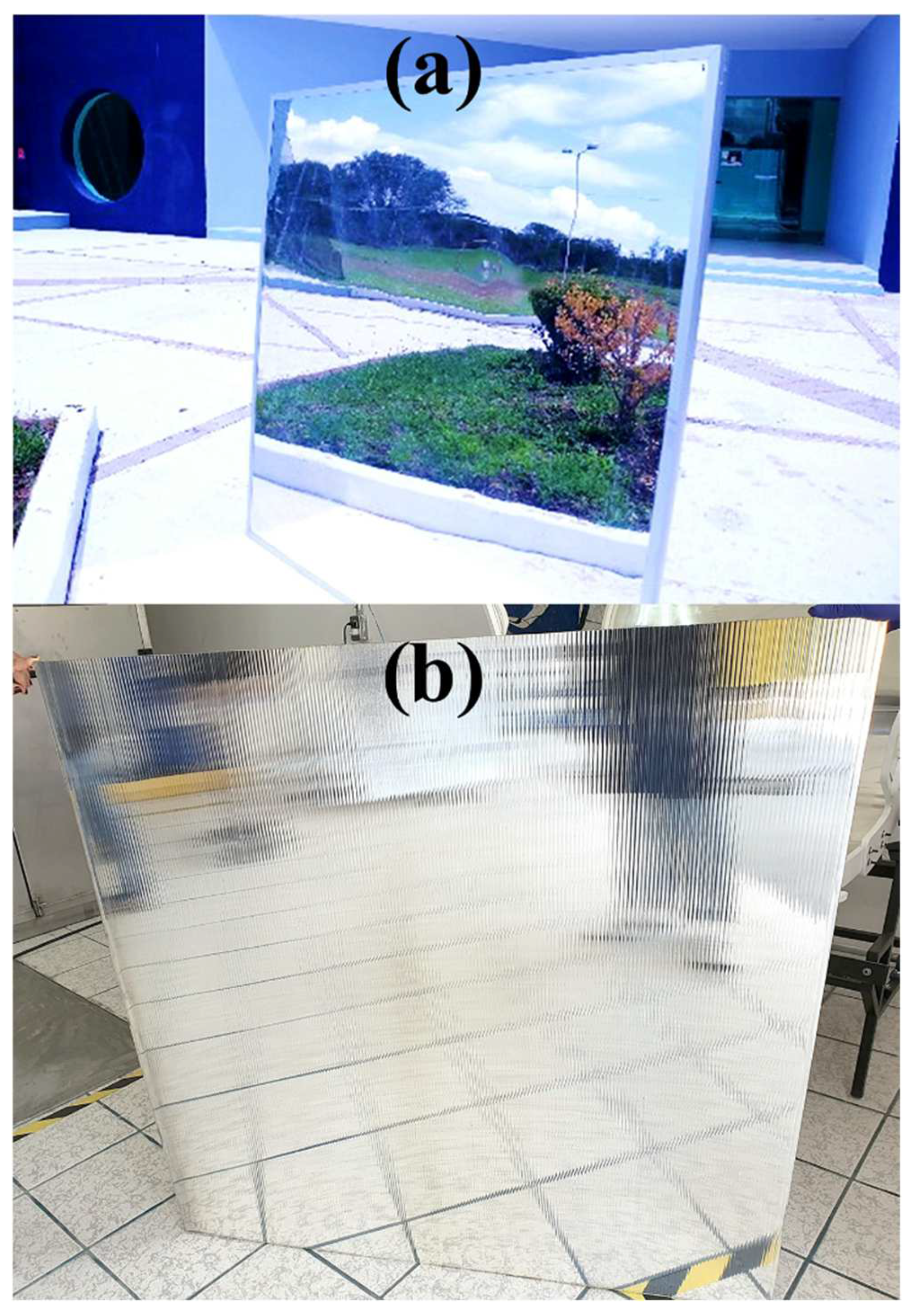
Square pieces of mirrors on polycarbonate substrates were successfully created by the DCP technique, which is an electroless metallization using an aerosol instead of dipping into a bath solution. Figure 4 shows two kinds of panels (1.2 m × 1.2 m), solid and twin wall sheets. This study makes no difference between them, since the tests were conducted on the silvery or silver/top coating regardless of the substrate type.
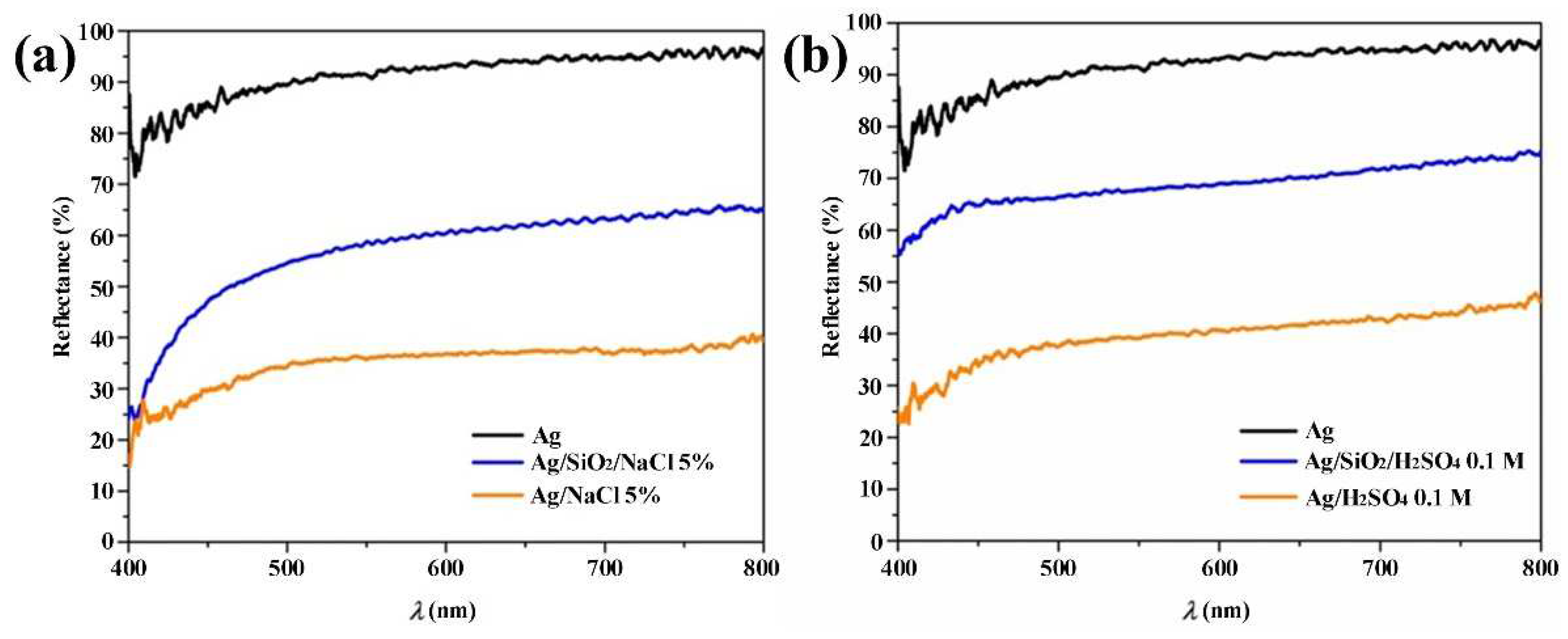
The following is an evaluation of the degradation of silver reflective surfaces exposed to environmental and accelerated weathering degradation. Reflectance is a parameter to quantify the optical quality of reflective surfaces for solar concentrators. In Figure 5, the reflectance curves of the samples that were exposed to controlled corrosive atmospheres are shown. Figure 5a shows the behavior of the reflectivity of the silver surfaces with and without coating in a 5% NaCl medium. The lowest percentage of reflectivity (36%) was that of the exposed surface without any coating compared to the coated surface, where an average of 62% was obtained. According to the optical images, a thinning was visualized in the metal layer, where moisture began to seep through the borders, and it began to degrade the silver layer. Similarly, black spots and tiny pores started to form on both surfaces, which caused the reflectivity percentage to decrease compared to the clean silver surface, which had 95% (black line).
Figure 5b shows the reflectance curves for the samples exposed to a corrosive atmosphere of H2SO4 0.1 M. The uncoated silver surfaces had the lowest percentage of reflectivity (40% average). The samples with coating had a percentage of reflectivity of 70% after the test. A decrease of 58% was observed on the uncoated surface and 26% on the coated surface compared to the clean silver surface (95%). The optical images showed that a sulfide layer began to form, which caused mechanical stress that broke the protective layer and caused detachments. Similarly, there were problems with adherence in some areas. The water that reached the inner silver surface came through the silica (SiO2) film pores or the interfaces, acted as a medium for the access of ions or molecules for the subsequent chemical reactions, and caused the dissolution of corrosion products [29].
The results from the characterization showed that the silver reflective layer was significantly changed by the corrosive atmospheres of NaCl and H2SO4. The reflectivity losses of the two surfaces tested in the salt fog were more significant than those of the tests with sulfate. The process of forming AgCl and dissolving it, which was visualized as a thinning of the silver layer, resulted in a more significant change in similar periods. The roughness change and the thickness reductions had more influence than an Ag2S layer formation. The silver thickness of these samples, usually about one hundred nanometers, reduces signifying, increasing the transmittance, considering that silver layers below about forty nanometers are transparent to the naked eye.
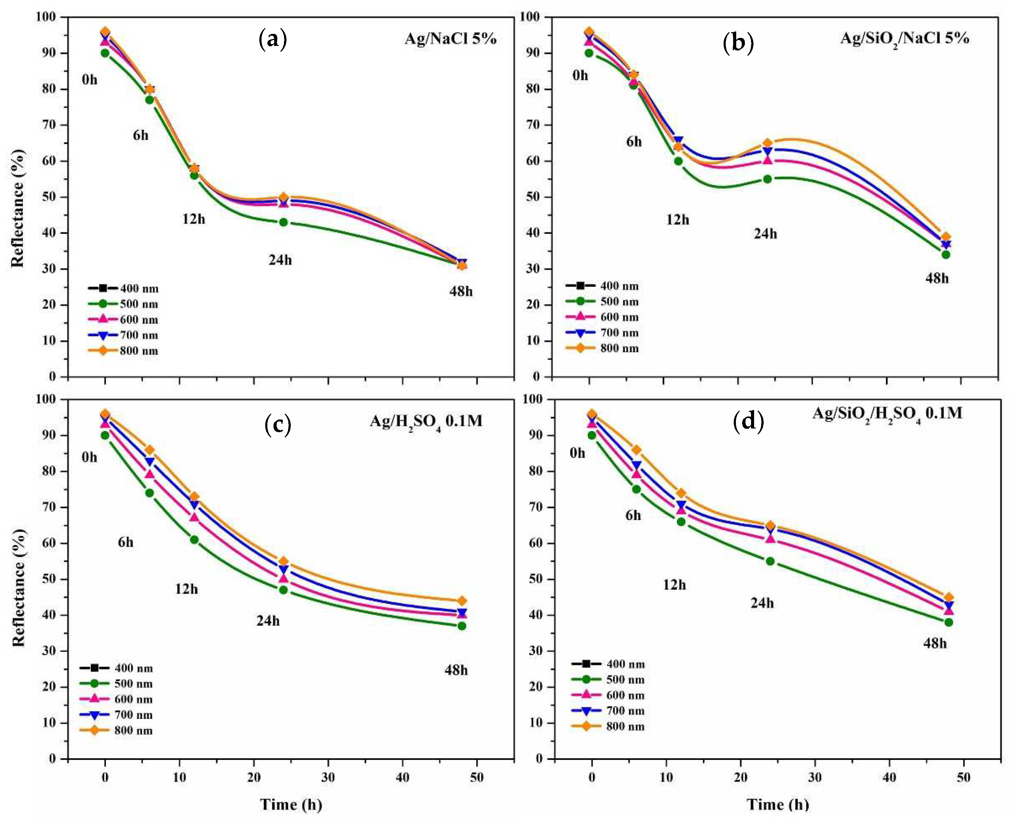
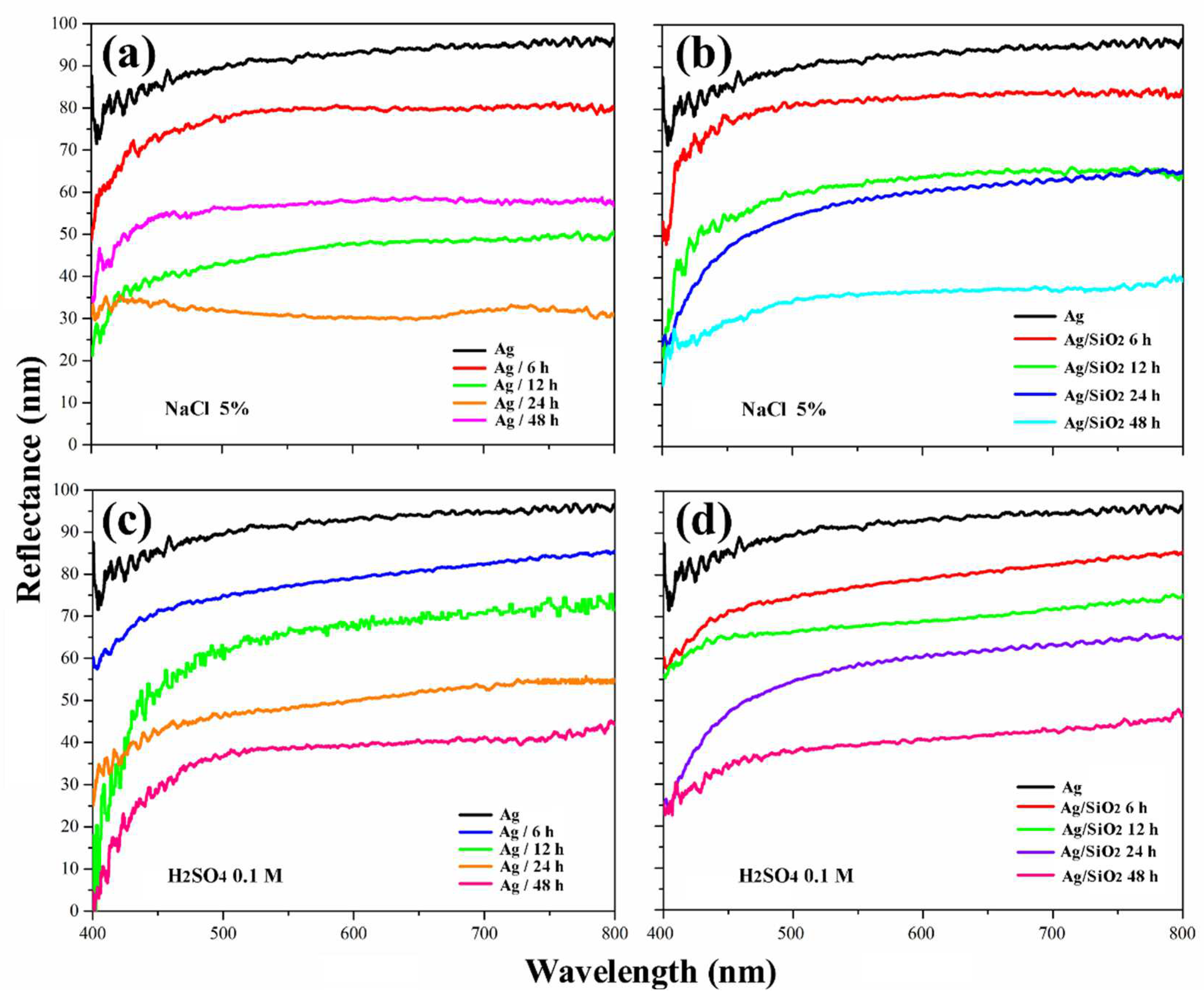
Figure 6a–d and Figure 7a–d show the reflectance as a function of time and wavelength, respectively, for a silver surface without and with a SiO2 protective coating. In these graphs, there were decrements in reflectivity with values of about 30% after 50 h. The protective coatings were composed of particles instead of continuous layers, which caused nearly similar behaviors to uncoated silver. The continuous and particulate coating made by APPJ using HMDSO depends on the process parameters, such as deposition rate, nozzle aperture, and distance to the substrate.
In addition to the reflectance changes using NaCl and H2SO4 fogs, the silver layer reflectance detriment with time is also affected by salt concentration, original silver coating thickness, temperature, and dry/wet alternating periods.
The conducted tests showed that airborne particles could lead to the corrosion of silver, even with protective layers. It was found that airborne particles combined with water condensation (dew) on the protective coating of silver became a source of S/Cl and extended the moisture time on the surface. In this way, a solution containing S or Cl can be formed on the protective layer. This solution first damages the protective layer, then permeates the layer, and finally damages the silver. This mechanism is demonstrated by evaluating experiments with bare silver and silver coated with a SiO2 layer [31]. Subsequently, water vapor penetrates the interface between the silver film and the substrate along the edges of the coating or through permeable defects, which causes delamination and blistering of the coating. The loss of reflectance was partly because of the scattered light of these blisters on the surface of the silver film.
Table 2 is a general description of the most significant degradation characteristics found in the reflective layer with and without protection at the end of each test with corrosive fog.
For the surfaces that were exposed to the outdoor ambient atmosphere, it is observed that the tarnished layer on the uncovered surface appeared as dark gray circular points on a light brown background. On the other hand, the tarnish on the silver film coated with SiO2 was mainly light brown.
The corrosion reactions of the silver exposed to the salt mist involve the dissolution of silver on the surface layer, which carried out the precipitation of AgCl on the surface. The migration and agglomeration of the silver atoms induced by Cl ions weaken the adhesion between the silver layer and the protective layer, which causes cracking and delamination of the latter.
In an aqueous medium, Cl ions begin to react with the surface, causing cracks to originate on the silver–substrate interface and extending toward the top coating. This leads to the formation of corrosion products on the coating surface in the form of AgCl (Figure 8a, Equation (2)). Meanwhile, evolutionary ions occur in the cathodic hydrogen reaction (Equation (3)), as reported elsewhere [27]. As chloride ions penetrate the coating and even the metal layer through minor imperfections, they create small channels that make pores on the surface.
Ag (s) → Ag+ + e
O2 + 2H2O + 4e → 4OH
These pores are joined, causing the metal layer detachment. Compared to the uncoated metal surface, the metal layer was removed more quickly with a NaCl solution. The micro-channels formed through the AgCl layer are likely the main conduction path at this stage. The representative scheme of the growth of corrosion compounds is visualized in Figure 8b.
The transport of ions through the corrosion product layer is essential for corrosion [49]. However, in the case of AgCl formation, the dominant load carrier within the AgCl layer is still controversial. Some researchers state that Ag+ is the leading charge carrier inside the micro-channels through the AgCl layer [50], while others suggest that Ag+ and Cl- contribute to the transport process.
In the test of accelerated weathering degradation of the coated silver surface with sulfate fog, the sulfide was deposited as a brown cover layer and caused the detachment of both the metallic deposit and the coating. In the case of the sulfate medium, the micrographs show that a similar mechanism produces the beginning of tarnishing to that of the medium with chlorides, which involves different paths that interconnect the protective layer and allow the entry of corrosive compounds into the silver layer. It is suggested that these permeation pathways are of microstructural origin and could correspond to the intergranular boundaries of the SiO2 layer.
Optical microscope images show that blisters form, having cracks connecting them. Subsequently, these blisters cause detachment of the metallic and protective layers. In the case of the outdoor ambient atmosphere, it can be deduced that the blisters were formed due to a reaction of silver and chemical species that permeate, forming compounds which have a higher volume than the original metal and finally breaking, creating the crack. As a result, the blisters become permeable to moisture and increase the local corrosion rate.
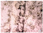
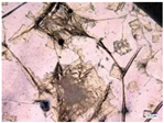
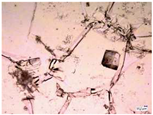
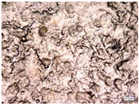
Figure 9 shows examples of typical failures that cause degradation of the reflective layer of the silver mirrors after exposure to environmental and accelerated weathering degradation obtained with the digital optical microscope. The evolution of the points was monitored over time, showing a small growth of specific points. Significant corrosion points or a large number of small points, smaller than 100 µm, cause the reflectance loss in this type of surface.
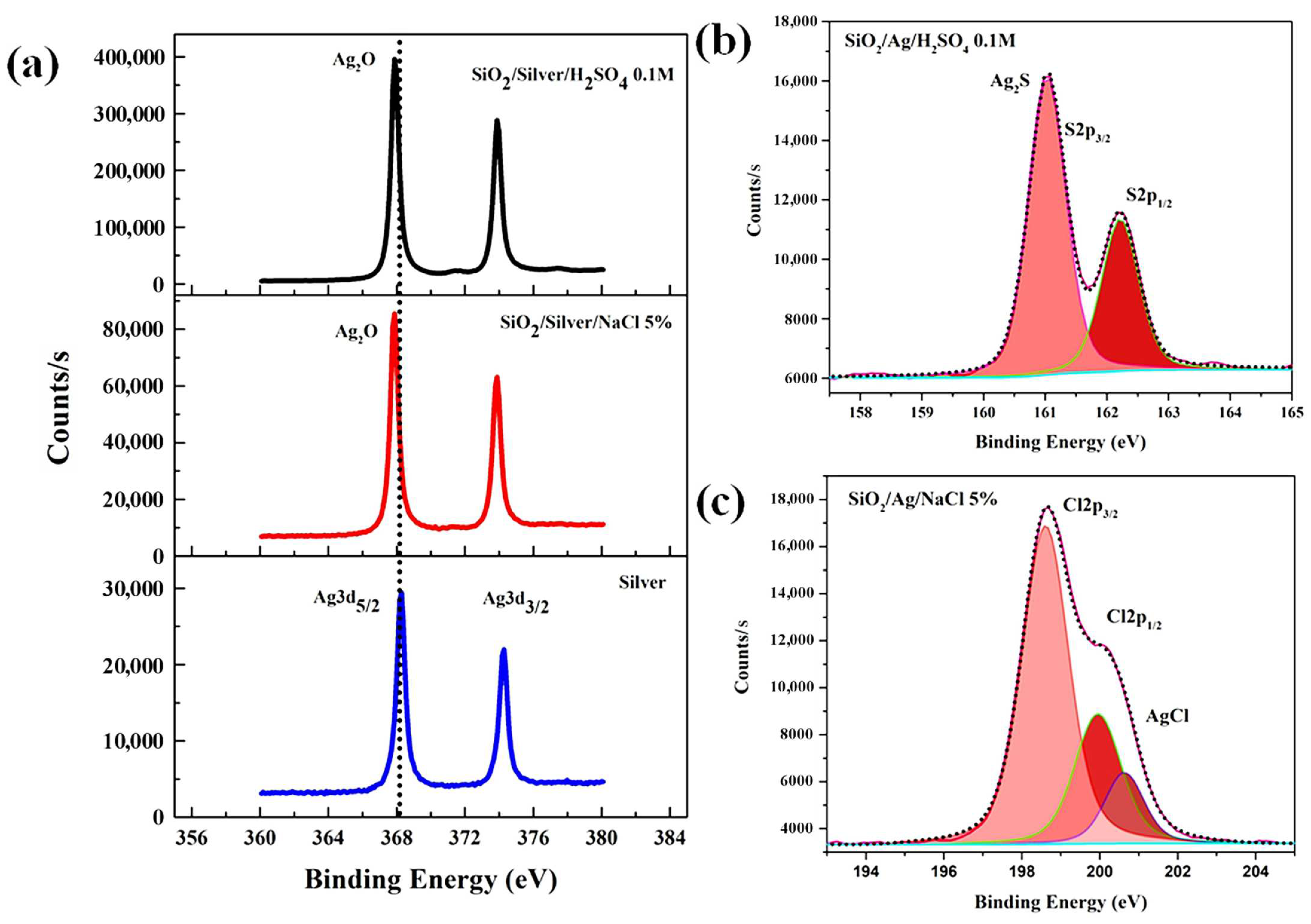
Figure 10 shows the results of the XPS analysis for bare and coated silver samples exposed to accelerated weathering degradation conditions in NaCl 5% and H2SO4 0.1 M. The XPS Ag3d core-level spectra (Figure 10a) show two peaks assigned to the 3d5/2–3d3/2 spin-orbit doublet (blue line), with the main peak at 368.2 eV. Likewise, the silver peaks of samples exposed to sulfate and chloride media were found at 367.8 eV and 374.1 eV, with shifts in the peak energy levels of about ± 0.4 eV. These energy shifts were attributed to the formation of Ag2O on the surface [28].
Figure 10b,c show the high-resolution spectra of Cl2p and S2p, respectively. Concerning the chlorine spectrum, the peak corresponding to the formation of AgCl with binding energy at 200.6 eV was observed. This can be corroborated in the optical microscope images, where the formation of a thick silver chloride layer was observed on the surface. Silver sulfide is a black corrosion product called tarnish, responsible for the loss of silver. After 48 h of exposure, the sulfide columns, consisting of Ag2S as shown by XPS (Figure 10c), have grown from the silver layer and through the protective layer and emerged locally above the surface. Sulfur stains initially grow on the periphery of the pores, which can be attributed to the imperfect seal of the protective layer. The generated cracks open new routes for the entrance of H2SO4 that can supply ions for the more significant growth of Ag2S. The silver layer began to be removed except in the pores where the silver was sulfide.
Figure 11 shows the results of the cyclic potentiodynamic polarization measurements and Table 3 shows the numerical values. In the case of the corrosion potential (Ecorr), it shifts to a lower potential, from 63.25 mV to 8.42 mV. The corrosion current (icorr) was determined by extrapolation of anodic (βa) and cathodic (βc) Tafel slopes. It decreases in the sample with the SiO2 coating. The pitting potential (Epitt) is the potential at which there is a change in the slope of the anodic zone, and this increase in current is attributed to the propagation of corrosion. It is higher in the sample coated with SiO2, which indicates that the pitting takes longer to propagate in that sample. These current and potential results indicate that the coated piece is less prone to corrosion. While the corrosion rate is slower and decreases by 2.28 times in the coated sample, this is due to the protective barrier effect of the SiO2 layer.
A Warburg element was added in both equivalent circuits in Figure 12 since the exchange current of Ag oxidation is very large. Therefore, the diffusion of Ag ions from the metal surface is the limiting stage of silver dissolution [51].
The results of electrochemical impedance spectroscopy are shown in Figure 12. The spectra of both samples approach capacitive semicircles. The largest corresponds to the sample with the protective coating, which is attributed to better resistance to corrosion through the barrier layer. The silver-coated sample was adjusted using a three-component equivalent circuit. In contrast, the silver-coated sample plus the protective SiO2 coating was adjusted using a five-component equivalent circuit due to the contribution of the second layer. The equivalent circuits are composed of the resistance of the electrolytic solution (Rs), constant phase element (CPE), and capacitor (C), attributed to the electrochemical double layer, the internal resistance of the coating (Rs), and the resistance to charge transfer (Rct), which is the value that indicates how easy it is for electrons to flow in the system and therefore is directly related to corrosion resistance. The corrosion rate of silica top coatings is 229% smaller for samples with silica layer protection against corrosion.
Table 4 shows the results of the equivalent circuits of both systems. Solution resistance and charge transfer resistance are increased in the sample with the SiO2 protective coating due to the inert protective layer that functions as a protective barrier. Therefore, the sample with the SiO2 coating is protected against corrosion by this barrier.
The Rct was 134% higher for samples with silica layer protection against corrosion. Comparing the corrosion rates (Table 3) with the Rct (Table 4), both indicate that the silica top coating acted as a physical barrier.

4. Conclusions

Silver mirrors on polycarbonate substrates were successfully made and tested, with a size of 1.2 m × 1.2 m. These mirrors are considered novel because (a) they were made on solid and twin wall polycarbonate sheets as substrates, (b) they were made by aerosol spraying of the reactants by the Dynamic Chemical Plating technique under environmental conditions, (c) atmospheric pressure plasma et coatings were deposited on the silver layer for protection, and (d) they were made using an automatized process.
After both environmental and accelerated weathering degradation tests, it was observed that the percentage of reflectance was decreasing on both surfaces with and without a protective coating. The accelerated weathering degradation tests evaluated the deterioration of the metal surface, which allowed proposing mechanisms for such deterioration behavior. The most common defects were silver sulfate spots on the reflector. These grow around the pores, which can be attributed to the imperfect seal of the protective layer and the formation of cracks, resulting in moisture diffusion into the metal–coating interface. Other defects were the detachment of the reflective surface of the polymer substrate, blisters, and holes. It was shown that the degradation of the reflective surface resulted in the occurrence of absorption and spreading mechanisms.
The accelerated weathering degradation tests in H2SO4 and NaCl led to the failure of the optical performance of the coated silver samples. However, the decrement of reflectance is not as significant as in the bare silver samples, where a significant loss in reflectance was observed after exposure, which was caused by the development of sulfide and silver chloride stains.
The main defects revealed a degradation mechanism similar to the mechanism of Ag2S column growth through the protection layer but involving different paths that pass through the protection layer and allow H2S to enter the silver layer. It was proposed that these pathways were of microstructural origin and could correspond to the incompletely fused intergranular boundaries of the SiO2 layer.
In the outdoor-exposed samples, pitting was found on the upper coating associated with silver corrosion points. Therefore, additional accelerated aging tests that simulate aggressive industrial environments would be significant.

Author Contributions

Conceptualization, C.M.L. and J.d.J.P.B.; methodology, C.M.L., J.d.J.P.B. and J.A.C.M.; validation, C.M.L., J.d.J.P.B. and J.A.C.M.; formal analysis, C.M.L., J.d.J.P.B. and J.A.C.M.; investigation, C.M.L., J.d.J.P.B., J.A.C.M., R.H.L., M.L.M.L., A.S.D. and Y.M.V.; resources, J.d.J.P.B. and Y.M.V.; data curation, C.M.L., J.d.J.P.B. and J.A.C.M.; writing—original draft preparation, C.M.L., J.d.J.P.B. and J.A.C.M.; writing—review and editing, C.M.L., J.d.J.P.B., J.A.C.M., R.H.L., M.L.M.L., A.S.D. and Y.M.V.; visualization, C.M.L., J.d.J.P.B. and J.A.C.M.; supervision, J.d.J.P.B. and Y.M.V.; project administration, J.d.J.P.B.; funding acquisition, J.d.J.P.B. All authors have read and agreed to the published version of the manuscript.

Funding

This work was funded by the National Council of Science and Technology CONACYT (México) through the Basic and/or Frontier Science grant no. 320114, and the National Laboratory of Graphenic Materials and the LANIAUTO are greatly appreciated. Authors appreciate the support of the “Fondo Sectorial CONACYT-SENER Sustentabilidad Energética” through grant 207450, and “Centro Mexicano de Innovación en Energía Solar (CeMIESol)”, within strategic project no. P62, “Prototype hybrid system of a supercritical CO2 expander with flat polycarbonate mirrors on automated heliostats”. Further, the authors give thanks to The World Bank and SENER, who support this work through grant no. 002/2017-PRODETES-PLATA.

Acknowledgments

The authors are thankful to all people who have been participating for many years that undertook the development process for fabricating solar mirrors. Thanks so much to all participants, which includes CIDETEQ’s students, CIDETEQ staff, CIDESI’s technical personnel, UAQ scientific and technical personnel, materials and chemical providers, and scientific collaborators from CINVESTAV—Unidad Merida, CINVESTAV—Unidad Saltillo, CINVESTAV—Unidad Querétaro, ICAT—UNAM, UTQ, UTSJR, and U T Tulancingo.

Conflicts of Interest

The authors declare no conflict of interest.

References

  1. Fernández-García, A.; Sutter, F.; Fernández-Reche, J.; Lüpfert, E. Mirrors. In The Performance of Concentrated Solar Power (CSP) Systems; Elsevier: Amsterdam, The Netherlands, 2017; pp. 67–98. [Google Scholar]
  2. Meyen, S.; Lüpfert, E.; Fernández-García, A.; Kennedy, C. Standardization of Solar Mirror Reflectance Measurements-Round Robin Test. Available online: http://www.nrel.gov/docs/fy11osti/49189.pdf (accessed on 3 October 2022).
  3. Barlev, D.; Vidu, R.; Stroeve, P. Innovation in concentrated solar power. Sol. Energy Mater. Sol. Cells 2011, 95, 2703–2725. [Google Scholar] [CrossRef]
  4. Desai, J.D.; Baviskar, P.K.; Hui, K.N.; Pathan, H.M. Quadrivalently Doped Hematite Thin Films for Solar Water Splitting. ES Energy Environ. 2018, 2, 21–30. [Google Scholar] [CrossRef] [Green Version]
  5. Gao, Y.; Wang, Z.; Ding, D.; Li, W.; Ma, Y.; Hao, Y.; Zhang, H. Novel Methods to Harness Solar Radiation for Advanced Energy Applications. ES Energy Environ. 2019, 5, 1–7. [Google Scholar] [CrossRef]
  6. Kennedy, C.E.; Terwilliger, K. Optical Durability of Candidate Solar Reflectors. J. Sol. Energy Eng. 2005, 127, 262–269. [Google Scholar] [CrossRef]
  7. Quaschning, V. Technical and economical system comparison of photovoltaic and concentrating solar thermal power systems depending on annual global irradiation. Sol. Energy 2004, 77, 171–178. [Google Scholar] [CrossRef]
  8. Badán, J.A.; Navarrete-Astorga, E.; Henríquez, R.; Martín, F.; Marotti, R.E.; Ramos-Barrado, J.R.; Dalchiele, E.A. Optical properties of silver nanoparticles deposited onto silicon substrates by different soft-solution processing techniques. Opt. Mater. 2020, 100, 109651. [Google Scholar] [CrossRef]
  9. Sutter, F.; Fernández-García, A.; Heller, P.; Anderson, K.; Wilson, G.; Schmücker, M.; Marvig, P. Durability Testing of Silvered-Glass Mirrors. Energy Procedia 2015, 69, 1568–1577. [Google Scholar] [CrossRef] [Green Version]
  10. Bennett, J.M.; Ashley, E.J. Infrared Reflectance and Emittance of Silver and Gold Evaporated in Ultrahigh Vacuum. Appl. Opt. 1965, 4, 221. [Google Scholar] [CrossRef]
  11. James, R.A.; Stapleton, A.J.; Hughes, A.; Charrault, E.; Zuber, K.; Switalska, E.; Evans, D.; Murphy, P.; Llusca, M. Metallic Adhesive Layers for Ag-Based First Surface Mirrors. Adv. Eng. Mater. 2018, 20, 1800106. [Google Scholar] [CrossRef]
  12. Thomas, N.L.; Wolfe, J.D. UV-Shifted Durable Silver Coating for Astronomical Mirrors; Dierickx, P., Ed.; SPIE: Bellingham, DC, USA, 2000; pp. 312–323. [Google Scholar]
  13. Amor, Y.B.; Sutter, E.; Takenouti, H.; Tribollet, B.; Boinet, M.; Faure, R.; Balencie, J.; Durieu, G. Electrochemical study of the tarnish layer of silver deposited on glass. Electrochim. Acta 2014, 131, 89–95. [Google Scholar] [CrossRef]
  14. Liang, D.; Allen, H.C.; Frankel, G.S.; Chen, Z.Y.; Kelly, R.G.; Wu, Y.; Wyslouzil, B.E. Effects of Sodium Chloride Particles, Ozone, UV, and Relative Humidity on Atmospheric Corrosion of Silver. J. Electrochem. Soc. 2010, 157, C146. [Google Scholar] [CrossRef] [Green Version]
  15. Graedel, T.E.; Leygraf, C. Corrosion Mechanisms for Nickel Exposed to the Atmosphere. J. Electrochem. Soc. 2000, 147, 1010. [Google Scholar] [CrossRef]
  16. Avenel, C.; Raccurt, O.; Gardette, J.-L.; Therias, S. Review of accelerated ageing test modelling and its application to solar mirrors. Sol. Energy Mater. Sol. Cells 2018, 186, 29–41. [Google Scholar] [CrossRef]
  17. Girard, R.; Delord, C.; Disdier, A.; Raccurt, O. Critical Constraints Responsible to Solar Glass Mirror Degradation. Energy Procedia 2015, 69, 1519–1528. [Google Scholar] [CrossRef] [Green Version]
  18. Li, L.; Li, Y.; Yu, H.; He, Y.-L. A feedforward-feedback hybrid control strategy towards ordered utilization of concentrating solar energy. Renew. Energy 2020, 154, 305–315. [Google Scholar] [CrossRef]
  19. Fernández-García, A.; Sutter, F.; Montecchi, M.; Sallaberry, F.; Heimsath, A.; Heras, C.; Baron, E.L.; Soum-Glaude, A. Parameters and Method to Evaluate the Reflectance Properties of Reflector Materials for Concentrating Solar Power Technology under Laboratory Conditions. Available online: https://www.solarpaces.org/wp-content/uploads/Document-1_SolarPACES_Reflectance-Guideline_V3.1.pdf (accessed on 3 October 2022).
  20. Utkin, A.I.; Zavitaev, E.V.; Yushkanov, A.A. Calculation of the electrical conductivity of a thin metal layer in the case of different specular reflectances of its surfaces. J. Surf. Investig. X-Ray Synchrotron Neutron Tech. 2016, 10, 962–968. [Google Scholar] [CrossRef]
  21. Sutter, F.; Fernández-García, A.; Heimsath, A.; Montecchi, M.; Pelayo, C. Advanced measurement techniques to characterize the near-specular reflectance of solar mirrors. AIP Conf. Proc. 2019, 2126, 110003. [Google Scholar]
  22. Heimsath, A.; Nitz, P. Scattering and specular reflection of solar reflector materials—Measurements and method to determine solar weighted specular reflectance. Sol. Energy Mater. Sol. Cells 2019, 203, 110191. [Google Scholar] [CrossRef]
  23. Alder, F.A.; Charrault, E.; Zuber, K.; Fabretto, M.; Patil, A.; Murphy, P.; Llusca, M. Fabrication of robust solar mirrors on polymeric substrates by physical vapor deposition technique. Sol. Energy Mater. Sol. Cells 2020, 209, 110476. [Google Scholar] [CrossRef]
  24. Anjum, F.; Fryauf, D.M.; Ahmad, R.; Phillips, A.C.; Kobayashi, N.P. Improving silver mirrors with aluminum oxynitride protection layers: Variation in refractive index with controlled oxygen content by radiofrequency magnetron sputtering. J. Astron. Telesc. Instrum. Syst. 2018, 4, 044004. [Google Scholar] [CrossRef]
  25. Limam, E.; Maurice, V.; Seyeux, A.; Zanna, S.; Klein, L.H.; Chauveau, G.; Grèzes-Besset, C.; Savin De Larclause, I.; Marcus, P. Local Degradation Mechanisms by Tarnishing of Protected Silver Mirror Layers Studied by Combined Surface Analysis. J. Phys. Chem. B 2018, 122, 578–586. [Google Scholar] [CrossRef] [PubMed]
  26. Fryauf, D.M. Effect of intermediate layers on atomic layer deposition-aluminum oxide protected silver mirrors. J. Astron. Telesc. Instrum. Syst. 2017, 3, 034001. [Google Scholar] [CrossRef]
  27. Leygarf, C.; Wallinder, I.O.; Tidblad, J.; Graedel, T. Atmospheric Corrosion; The Electrochemical Society Series; John Wiley & Sons, Inc.: Hoboken, NJ, USA, 2016; pp. 337–347. [Google Scholar]
  28. Wan, Y.; Wang, X.; Wang, X.; Li, Y.; Sun, H.; Zhang, K. Determination and generation of the corrosion compounds on silver exposed to the atmospheres. Int. J. Electrochem. Sci. 2015, 10, 2336–2354. [Google Scholar]
  29. Folgner, K.A.; Chu, C.-T.; Lingley, Z.R.; Kim, H.I.; Yang, J.-M.; Barrie, J.D. Environmental durability of protected silver mirrors prepared by plasma beam sputtering. Appl. Opt. 2017, 56, C75. [Google Scholar] [CrossRef]
  30. Chiou, A.-H.; Chien, T.-C.; Su, C.-K.; Lin, J.-F.; Hsu, C.-Y. The effect of differently sized Ag catalysts on the fabrication of a silicon nanowire array using Ag-assisted electroless etching. Curr. Appl. Phys. 2013, 13, 717–724. [Google Scholar] [CrossRef]
  31. Limam, E.; Maurice, V.; Seyeux, A.; Zanna, S.; Klein, L.H.; Chauveau, G.; Grèzes-Besset, C.; Savin De Larclause, I.; Marcus, P. Role of SiC substrate surface on local tarnishing of deposited silver mirror stacks. Appl. Surf. Sci. 2018, 436, 1147–1156. [Google Scholar] [CrossRef]
  32. Mishra, S.K.; Kumar, V.; Tiwari, S.K.; Mishra, T.; Angula, G.; Adhikari, S. Development and degradation behavior of protective multilayer coatings for aluminum reflectors for solar thermal applications. Thin Solid Film. 2016, 619, 202–207. [Google Scholar] [CrossRef]
  33. García-Segura, A.; Fernández-García, A.; Ariza, M.J.; Sutter, F.; Valenzuela, L. Effects of reduced sulphur atmospheres on reflector materials for concentrating solar thermal applications. Corros. Sci. 2018, 133, 78–93. [Google Scholar] [CrossRef]
  34. Xie, P.; Li, Y.; Hou, Q.; Sui, K.; Liu, C.; Fu, X.; Zhang, J.; Murugadoss, V.; Fan, J.; Wang, Y.; et al. Tunneling-induced negative permittivity in Ni/MnO nanocomposites by a bio-gel derived strategy. J. Mater. Chem. C 2020, 8, 3029–3039. [Google Scholar] [CrossRef]
  35. Zhang, Q.; Liang, Q.; Zhang, Z.; Kang, Z.; Liao, Q.; Ding, Y.; Ma, M.; Gao, F.; Zhao, X.; Zhang, Y. Electromagnetic Shielding Hybrid Nanogenerator for Health Monitoring and Protection. Adv. Funct. Mater. 2018, 28, 1703801. [Google Scholar] [CrossRef]
  36. Kong, L.; Yin, X.; Xu, H.; Yuan, X.; Wang, T.; Xu, Z.; Huang, J.; Yang, R.; Fan, H. Powerful absorbing and lightweight electromagnetic shielding CNTs/RGO composite. Carbon 2019, 145, 61–66. [Google Scholar] [CrossRef]
  37. Kargar, F.; Barani, Z.; Balinskiy, M.; Magana, A.S.; Lewis, J.S.; Balandin, A.A. Dual-Functional Graphene Composites for Electromagnetic Shielding and Thermal Management. Adv. Electron. Mater. 2019, 5, 1800558. [Google Scholar] [CrossRef]
  38. Jia, Z.; Wang, C.; Feng, A.; Shi, P.; Zhang, C.; Liu, X.; Wang, K.; Wu, G. A low-dielectric decoration strategy to achieve absorption dominated electromagnetic shielding material. Compos. Part B Eng. 2020, 183, 107690. [Google Scholar] [CrossRef]
  39. Gilliam, M.A.; Farhat, S.A.; Garner, G.E.; Stubbs, B.P.; Peterson, B.B. Characterization of the deposition behavior and changes in bonding structures of hexamethyldisiloxane and decamethylcyclopentasiloxane atmospheric plasma-deposited films. Plasma Process. Polym. 2019, 16, e1900024. [Google Scholar] [CrossRef]
  40. Hossain, M.M.; Trinh, Q.H.; Nguyen, D.B.; Sudhakaran, M.S.P.; Mok, Y.S. Robust hydrophobic coating on glass surface by an atmospheric-pressure plasma jet for plasma-polymerisation of hexamethyldisiloxane conjugated with (3-aminopropyl) triethoxysilane. Surf. Eng. 2019, 35, 466–475. [Google Scholar] [CrossRef]
  41. Trinh, Q.H.; Nguyen, D.B.; Hossain, M.M.; Mok, Y.S. Deposition of superhydrophobic coatings on glass substrates from hexamethyldisiloxane using a kHz-powered plasma jet. Surf. Coat. Technol. 2019, 361, 377–385. [Google Scholar] [CrossRef]
  42. Gotoh, K.; Shohbuke, E.; Ryu, G. Application of atmospheric pressure plasma polymerization for soil guard finishing of textiles. Text. Res. J. 2018, 88, 1278–1289. [Google Scholar] [CrossRef]
  43. Shohbuke, E.; Gotoh, K. Control of Wettability and Antifouling Property of Polyester Fabric by Atmospheric Pressure Plasma Jet Treatments. J. Jpn. Res. Assoc. Text. 2018, 59, 359–368. [Google Scholar] [CrossRef]
  44. Pérez-Bueno, J.J.; Vasquez-García, S.R.; García-González, L.; Vorobiev, Y.V.; Luna-Bárcenas, G.; González-Hernández, J. Optical processes in PMMA, SiO2, and hybrid organic-inorganic sol-gel films colored with rhodamine 6GDN. J. Phys. Chem. B 2002, 106, 1550–1556. [Google Scholar] [CrossRef]
  45. Díaz-Flores, L.L.; Pérez-Bueno, J.J.; Ramírez-Bon, R.; Espinoza-Beltrán, F.J.; Vorobiev, Y.V.; González-Hernández, J. Improved light stability of colored SiO2 coatings containing organic and metalorganic dye molecules. J. Vac. Sci. Technol. A Vac. Surf. Film. 2000, 18, 1579–1583. [Google Scholar] [CrossRef]
  46. ASTM D1654-08(2016)e1; Standard Test Method for Evaluation of Painted or Coated Specimens Subjected to Corrosive Environments. ASTM International: West Conshohocken, PA, USA, 2016.
  47. ASTM B117-19; Standard Practice for Operating Salt Spray (Fog) Apparatus. ASTM International: West Conshohocken, PA, USA, 2019.
  48. Keast, V.J. Atmospheric Corrosion of Silver and Silver Nanoparticles. Corros. Mater. Degrad. 2022, 3, 221–234. [Google Scholar] [CrossRef]
  49. Payer, J.H.; Ball, G.; Rickett, B.I.; Kim, H.S. Role of transport properties in corrosion product growth. Mater. Sci. Eng. A 1995, 198, 91–102. [Google Scholar] [CrossRef]
  50. Jin, X.; Lu, J.; Liu, P.; Tong, H. The electrochemical formation and reduction of a thick AgCl deposition layer on a silver substrate. J. Electroanal. Chem. 2003, 542, 85–96. [Google Scholar] [CrossRef]
  51. Cruz-Manzo, S.; Greenwood, P. Analytical transfer function to simulate the dynamic response of the finite-length Warburg impedance in the time-domain. J. Energy Storage 2022, 55, 105529. [Google Scholar] [CrossRef]
Figure 1. Automated facilities to metallize and coat mirrors for CSP systems. The electroless metallization cabin (left side), entrance, and automatic polycarbonate sheets switching where the heat surface pre-treatment is applied (center), and APPJ cabin (right side).
Sustainability 14 16360 g001
Figure 2. Process schemes for making a silvery mirror (a) without and (b) with a protective SiO2 coating deposited using HMDSO.
Sustainability 14 16360 g002
Figure 3. (a) Sixteen mirrors of solid polycarbonate conforming a heliostat. (b) Mirror sheets at the moment of being installed with aluminum frames.
Sustainability 14 16360 g003
Figure 4. Plated polycarbonate mirrors using (a) solid and (b) twin wall sheets.
Sustainability 14 16360 g004
Figure 5. Reflectance curves of the accelerated weathering degradation tests of three different surfaces, bare silver, silver, and SiO2/silver, after exposure to a corroding medium, with two kinds of ion sources: (a) NaCl 5% and (b) H2SO4 0.1 M. The spectra were taken using an aluminum standard as a white reference.
Sustainability 14 16360 g005
Figure 6. Reflectance curves vs. time of the accelerated weathering degradation tests of bare silver and silver with a SiO2 protective coating in two kinds of ion sources: (a,c) NaCl 5% and (b,d) H2SO4 0.1 M, respectively.
Sustainability 14 16360 g006
Figure 7. Reflectance curves vs. wavelength of the accelerated weathering degradation tests of bare silver and silver with a SiO2 protective coating in two kinds of ion sources: (a,c) NaCl 5% and (b,d) H2SO4 0.1 M, respectively.
Sustainability 14 16360 g007
Figure 8. (a) Proposed degradation path for a silver surface coated in a NaCl medium. (b) Scheme of the growth of corrosion compounds through micro-channels and the evolution on the coating surface to the metal layer in a NaCl medium.
Sustainability 14 16360 g008
Figure 9. Optical microscope images of the most common corrosion points on silver reflective surfaces after 96 h of accelerated weathering degradation and after six months of environmental weathering degradation: (a) reflective surface exposed to the environment, (b) reflective surface with coating exposed to the environment, (c) reflective surface with coating in NaCl 5% aqueous solution, (d) reflective surface with coating in a H2SO4 0.1 M aqueous solution. The scale bars in blue lines represent 10 µm.
Sustainability 14 16360 g009
Figure 10. High-resolution XPS spectrum of (a) Ag3d, (b) S2p, and (c) Cl2p of metallic surfaces with protective coatings tested in accelerated environments of 5% NaCl and 0.1 M H2SO4.
Sustainability 14 16360 g010
Figure 11. Cyclic potentiodynamic polarization results conducted in H2SO4 0.5 M.
Sustainability 14 16360 g011
Figure 12. EIS measurements and equivalent circuits conducted in H2SO4 0.5 M.
Sustainability 14 16360 g012
Table 1. Parameters at the location where the tests were conducted (20°41′51″ N, 100°26′23″ W) after six months of exposure.
ParameterValue
UV index8.1 index (high)
Relative humidity (%)45
Temperature (°C)24
Solar radiation index610 W/m2
Table 2. Analysis of microscopic degradation of reflective surfaces with and without a protective coating, in different accelerated weathering degradation tests (after 96 h) and environmental tests (after six months), where coating defects are observed. The scale bars are shown as blue lines representing 10 or 20 µm.
Samples with a Protective CoatingSamples without Coating
Environmental weathering degradationSustainability 14 16360 i001Sustainability 14 16360 i002Sustainability 14 16360 i003Sustainability 14 16360 i004
Accelerated weathering degradation (NaCl 5%)Sustainability 14 16360 i005Sustainability 14 16360 i006Sustainability 14 16360 i007Sustainability 14 16360 i008
Accelerated weathering degradation (H2SO4 0.1 M)Sustainability 14 16360 i009Sustainability 14 16360 i010Sustainability 14 16360 i011Sustainability 14 16360 i012
Table 3. Analysis of Tafel slopes.
SampleβaβcEcorr
(mV)
Icorr
(µA/cm2)
Epitt
(V)
Corrosion Rate (mmpy)
Ag Coating174.167 ± 36120.3 ± 3263.25 ± 37.331.24 ± 0.590.13 ± 0.020.0208 ± 0.01
Ag Coating + SiO2 layer185.5 ± 26150.3 ± 298.42 ± 12.780.54 ± 0.130.21 ± 0.060.0091 ± 0.003
Table 4. EIS results for surfaces of Ag coating and Ag coating + silica layer.
SampleRs (Ω)C (F)Rtc (Ω)CPE-T (F.s(n−1))CPE-P (F.s(n−1))Rtc (Ω)
Ag Coating25.52 ± 10.13--0.000544 ± 0.00030.8437 ± 0.05930,937.5 ± 13,408
Ag Coating + SiO2 layer210.2 ± 8.207.24 × 10−8205.12 ± 11.714.81 × 10−5 ± 1.2 × 10−50.0061 ± 0.00241,527.93 ± 1572
Publisher’s Note: MDPI stays neutral with regard to jurisdictional claims in published maps and institutional affiliations.