Article

Installation and Performance Study of a Vertical-Axis Wind Turbine Prototype Model

1
Elitte College of Engineering, Affiliated: MAKA University of Technology, Kolkata 700113, India
2
Department of Mechanical Engineering, Elitte College of Engineering, Affiliated: MAKA University of Technology, Kolkata 700113, India
3
Department of Electrical Engineering, Elitte College of Engineering, Affiliated: MAKA University of Technology, Kolkata 700113, India
*
Author to whom correspondence should be addressed.
Sustainability 2022, 14(23), 16084; https://doi.org/10.3390/su142316084
Submission received: 6 November 2022 / Revised: 22 November 2022 / Accepted: 29 November 2022 / Published: 1 December 2022
(This article belongs to the Special Issue Renewable Energy Technologies for Sustainable Development)

Abstract

:
Amongst various sources of renewable energy, the kinetic energy of blowing wind has environmental friendliness and easy availability, together with other benefits. The wind energy is converted into usable electrical energy by means of a robust device termed a wind turbine. To carry out a performance study of such a device, a small-scale model vertical-axis wind turbine was installed at the laboratory and was run by artificial wind energy produced by a pedestal fan for low and medium speeds and a blower for higher speeds. The variation in critical parameters such as output power and voltage with different speeds was studied. The average output power and voltage were observed to increase with average shaft speed with linear and curvilinear patterns, respectively. The vibration produced at the bearing shaft resulting from the rotating components was analyzed as well. As observed, the peak values of critical vibration parameters such as displacement, velocity, acceleration, and frequency mostly varied curvilinearly with average shaft speeds. To study the applicability of the power generation, an electronically controlled automatic drip irrigation system was allowed to run by the wind turbine and important observations were made. Theoretical analyses (numerical and analytical) of the wind flow and power generation were also performed.

1. Introduction

Renewable energy is derived from natural resources that are replenished constantly and available in various forms, such as sunlight, ocean waves and currents, wind, biomass and biofuels, geothermal sources, and hydropower, among others [1]. The necessity of a quick and sustainable shift to renewable energy is of utmost importance, not only because of limited fossil fuel storage on Earth but also due to the adverse environmental impact of burning coal, oil, or gas to produce conventional energy [2]. Numerous advantages of using renewable energy resources include reduced global warming and greenhouse gas emission, enhanced public health, inexhaustibility with reliability and resilience, steady energy costing, and social development in terms of employment generation, etc. [3]. Since the last decade, the utilization of renewable energy resources has been increasing significantly, aiming towards forming about 30% of the total global energy consumption in the year 2022 [4].
Wind energy is increasingly becoming a popular, sustainable, and renewable energy source that is utilized to generate electricity. In recent times, wind has supplied about 6% of the world’s electricity on average [5]. Wind energy has been observed to be maximally environmentally friendly, while having the lowest water consumption demands and with optimum social impacts, compared to the other sources of renewable energy [6,7]. Wind farms consist of many individual wind turbines, which are connected to the electric power transmission network. Since wind speed is variable depending on space and time, adequate power management techniques with predictable weather variation are essential [8].
The mathematical expression of energy and power associated with wind flowing through a surface is given as [8]
E t = γ v 3 A t 2 g
P = E t t = γ v 3 A 2 g
where Et is the total energy at a time duration of t, γ is the unit weight of air, A is the area through which the wind passes, g is the gravitational acceleration, and P is the power.
The total extractable wind power available in a specific location has been observed to be greater than human power use from all sources, although the average wind speed does not solely specify the amount of energy that may be produced by a wind turbine. However, to assess the prospective wind power at a specific site, probability distribution analysis is often conducted [9].
The kinetic energy of wind is converted into electrical energy by a robust device equipped with mechanical, electrical, and structural components, termed a wind turbine (WT). Due to a fair availability of steady and continuous wind speed, offshore regions are mostly preferred to install WTs. Statistical analysis reveals that the mean annual offshore wind speed may vary in the ranges of 12–13 m/s; thus the average angular speed of WT propellers usually varies between 10 and 20 rpm [10,11]. This speed is stepped up through a gear mechanism several times which is in turn utilized to produce electricity by a suitably designed generator. For smaller turbines, DC machines, synchronous machines, and squirrel-cage induction machines are traditional practices, whereas in the cases of medium and large WTs, a doubly-fed induction generator is the current trend, while permanent-magnet, switched reluctance, and high-temperature superconducting generators have been developed as well [12]. The generated electricity is stored in a high-capacity storage battery and systematically supplied through an appropriate power-transmission system [13]. A flowchart representing the stepwise operation of a WT is presented in Figure 1a.
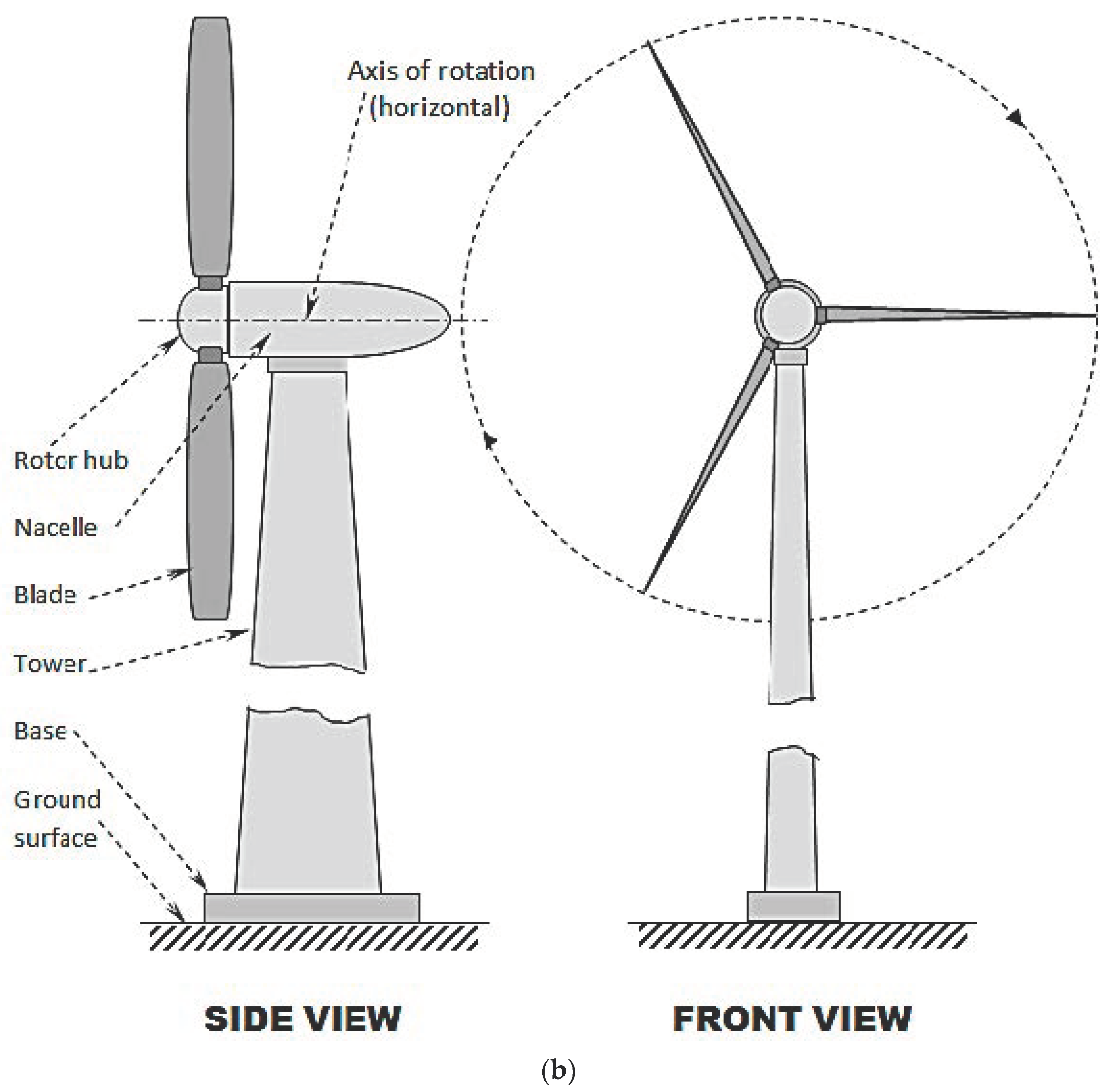
Based on the special orientation of the propeller axis, the WTs are primarily classified into two groups: vertical axis and horizontal axis. Vertical-axis WTs may be drag-based or lift-based devices, either having solid vanes or vertical airfoils, respectively, capable of operating independently of the wind direction, thus being quite convenient in urban-region applications. The horizontal-axis WTs, on the other hand, can be either upwind or downwind, equipped with a yaw drive and motor to turn the nacelle windward. These turbines are typically either two- or three-bladed and are conventionally used in offshore regions [13]. Sketches portraying typical vertical- and horizontal-axis WTs are shown in Figure 1b,c, respectively.
As mentioned above, a typical WT consists of mechanical, electrical, and structural components, apart from the supporting foundation [14]. A brief review of the existing literature reveals that there are significant past research contributions, including laboratory model studies [15,16,17], full-scale field investigations [18,19,20], analyses [21,22,23], and numerical [24,25,26] works, along with appropriate design recommendations [27,28]. Limited studies were carried out in the past on the performance analysis and parametric studies of small-scale wind turbines [29,30].
Although new technology-based innovative wind turbines have also been introduced such as harmony turbines, tulip turbines, solar–wind hybrid systems, etc. [31,32,33], they are still in the infancy stage from the viewpoint of commercial usages, while their working principles are similar to the conventional vertical- or horizontal-axis WTs.
Vertical-axis wind turbines are usually lift-based, comprising tall, vertical airfoils that are capable of generating electricity even at low wind speeds. They are typically smaller in overall size and hence easy to install for application in urban localities where wind directions and speeds change randomly. Horizontal-axis wind turbines, on the other hand, comprise large and tall structures and are most suitable in offshore zones. The rotor hub in the horizontal axis needs to be rotated windward for greater efficiency. Although having comparatively lower power efficiency, vertical-axis wind turbines are often preferred for their versatile usages [13,14,15,16,17,18,19,20,21,22,23,24,25,26,27,28,29,30,31,32,33,34].
Mathematical analyses of the suitability of different forms of clean and renewable energies were carried out in the recent past [35,36,37,38]. Based on review models related to decision approaches for clean energy systems, it was found that wind energy constituted of highest proportion due to convenience and availability.
A Performance study of a small-scale wind turbine is required to have an in-depth idea about salient features such as power generation efficiency, shaft vibration, wind flow characteristics, etc. In this paper, these studies have been performed through experimental and theoretical analyses. The research findings can be utilized to have an overall idea of how such a study can be replicated in the case of a full-scale wind turbine, which will ultimately assist in the design of such turbines for practical usage.

2. Objective and Research Methodology

The objective of the current investigation is to conduct in-depth performance studies of a model vertical-axis wind turbine, including experimental and theoretical (analytical and numerical) studies as well as the application potential of the turbine. The correlations between critical mechanical and electrical parameters such as wind speed, shaft angular velocity, electrical power and voltage, vibration analysis, and power efficiency have been investigated. The power generated by the turbine was utilized to operate an electronic drip irrigation device and critical parameters were studied.

3. Installation

A typical small-scale model of a vertical-axis wind turbine with all mechanical, electrical, and structural accessories was collected from the manufacturer, Nevon Projects Solutions Private Limited [39]. As supplied by the manufacturer, the capacity of the turbine was 10 Watts. Since the individual components were in isolated conditions, the authors assembled them to form the model turbine, and the same was fixed to a rigid base and cemented to the laboratory floor.
Different electrical and mechanical components of the model wind turbine were obtained from the manufacturer. They included the electrical generator and its circuit, the blades and their accessories, the shafts, the base plate, etc. These individual components were assembled and then extensive parametric studies were conducted, as detailed in the paper. However, the authors do agree that a prototype design is required even for small-scale model turbines and this is being done in future works.

3.1. Mechanical Components

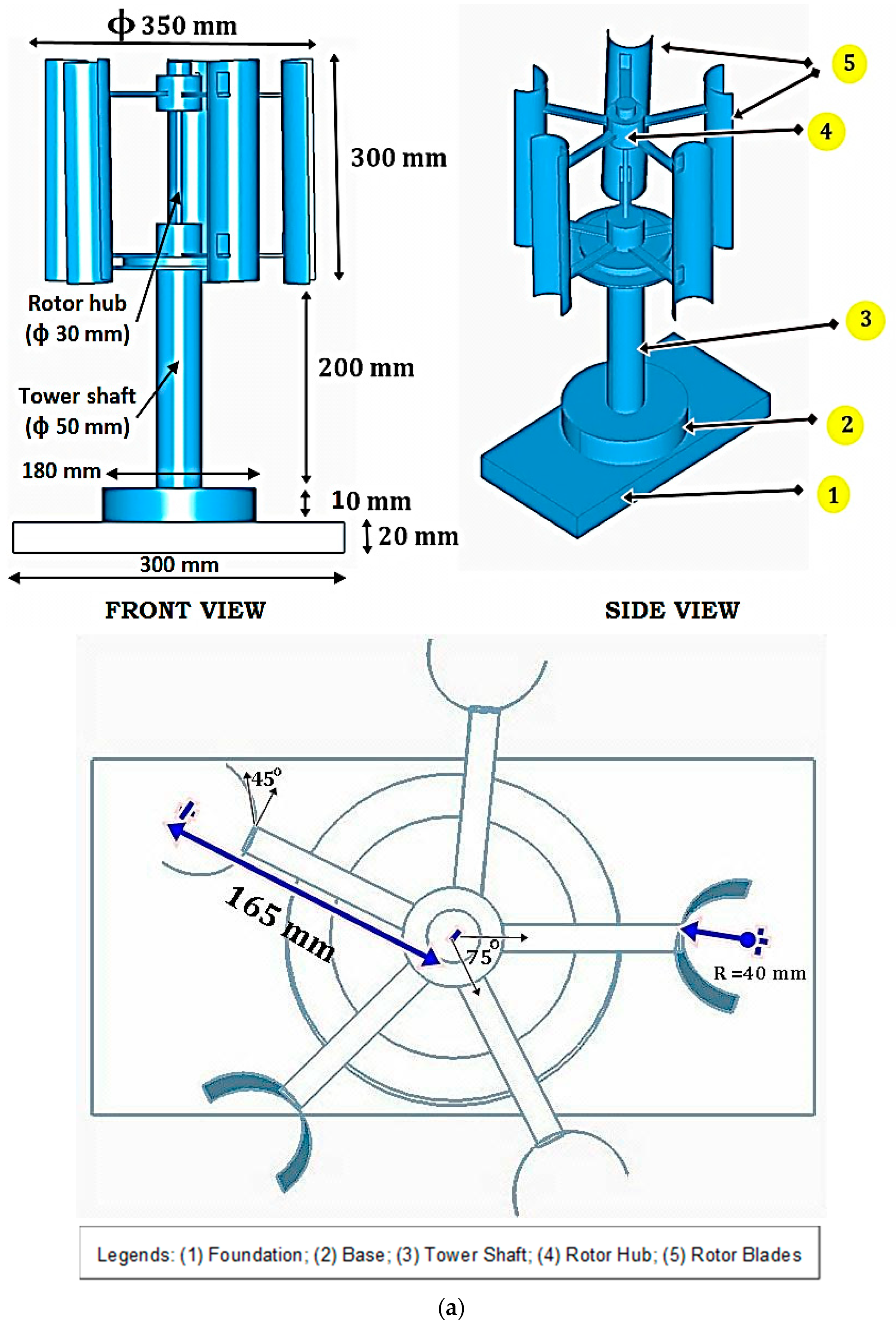
The schematic diagrams and photographic views of the installed vertical-axis wind turbines are portrayed in Figure 2. As observed, the rotor hub (diameter: 30 mm) was attached to the tower shaft (diameter: 50 mm) by means of a telescopic connection with a ball bearing to minimize the frictional resistance during rotation. Five equally spaced aluminum blades were connected to the rotor hub, each of which being a circular arc with an inner radius of 40 mm and a semi-arc angle of 45°; the projected size of each blade was 58 mm × 300 mm. Curved-type multi-blades (five blades) made of aluminum alloy (6061-T6) were utilized in the model vertical-axis wind turbine used in the study. Aluminum alloy 6061-T6 is widely used in many sectors including aircraft, defense, automobiles, and marine areas due to its satisfactory strength and stiffness, low weight, and better corrosion resistance properties [40,41]. Thus, such material leads to a reduction in the overall weight of the wind turbine while increasing its durability, thereby improving its performance. The tower shaft is rigidly connected to the steel circular base of 180 mm diameter and 10 mm thickness, which is in turn connected to a wooden square base of size 300 mm and 20 mm thickness. The wooden base is permanently bolted to the laboratory floor. The rotation of the shaft was initiated by artificial air flow by a pedestal fan which is capable of operating at low, medium, and high speeds. Since the WT is not equipped with any step-up gear system, an air blower was used to achieve very high speeds of the rotor shaft. The rotational speed of the shaft was measured by a laser-beam-operated tachometer.

3.2. Electrical Components

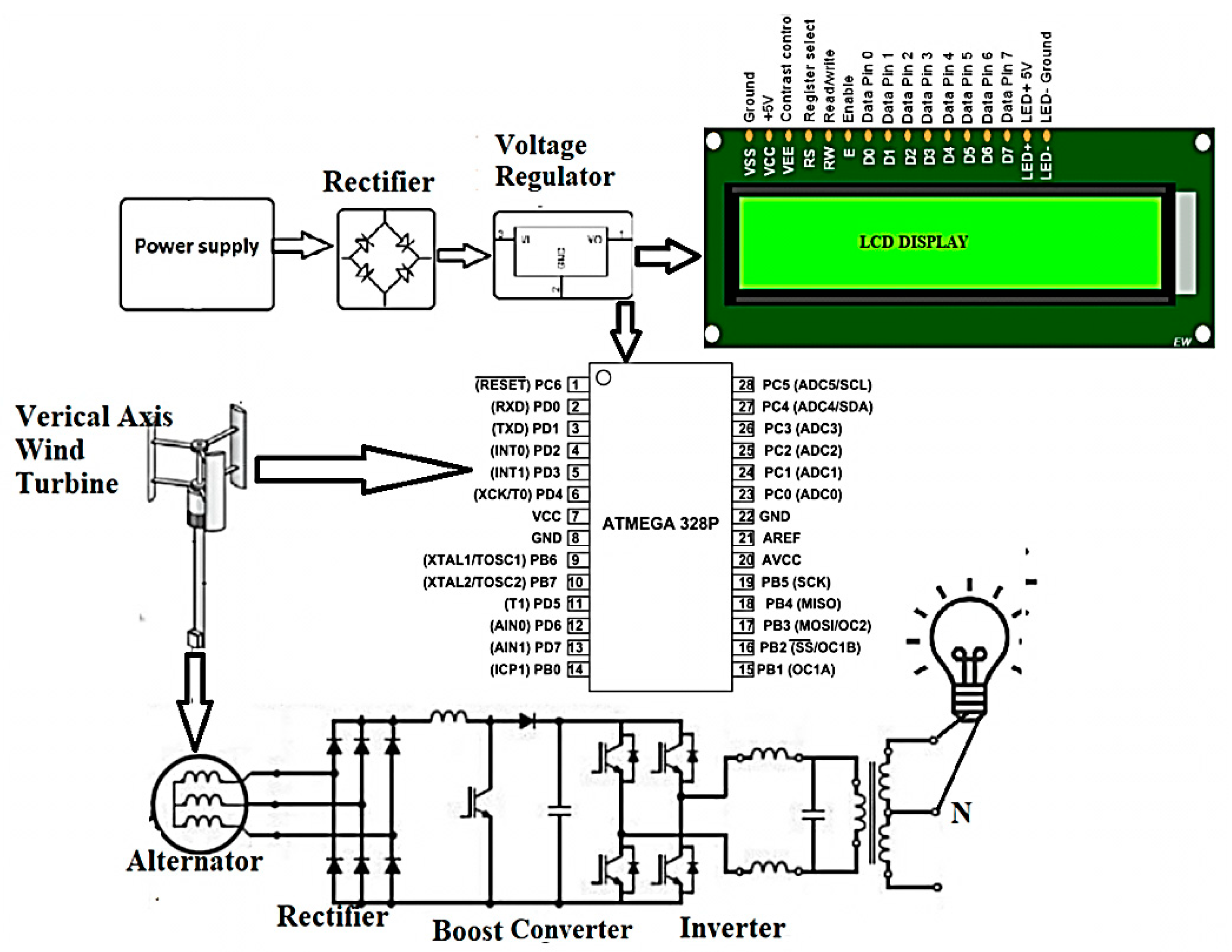
The electrical framework was controlled by an ATmega 328 microcontroller, DC motor, 12 V battery, DC inverter, MOSFET switch, LCD, and transformer. The circuit diagram of the electrical components is depicted in Figure 3. The rotational energy of the rotor shaft was converted into electrical energy by a dynamo, while the power output was shown on the LCD monitor. The system charges the 12 V storage battery. When the battery is switched on, the inverter changes the power output from DC to AC and the step-up transformer expands the voltage required to run the device; the voltage is managed by the transistor MOSFET. Both the DC and AC voltages were measured by an Industrial True RMS multi-meter.

4. Performance Study

For the performance study of the model WT, the variation in power output and other critical parameters for different shaft speeds were studied. To ascertain a wide range of variation, the turbine blades were allowed to rotate by the wind emerging from a pedestal fan as well as a blower. Five different speed categories were selected. For very low, low, and medium speeds, the pedestal fan was at different speeds (adjusted by a fan regulator), while for high speeds, the blower was used. To initiate a very high speed of the turbine shaft, both the blower and the peak speed of the pedestal fan were used. Since both the fan and the blower were run by an electrical power supply in the laboratory, it is likely that their speeds vary at different time instances due to possible alterations in the main power supply. Hence, for each of the above speed categories, the variations of critical parameters at different time instances were also recorded, as presented in Table 1.
One of the primary objectives of the current study was to investigate the variation in power and voltage outputs with different angular velocities of the rotor hub. Thus, it was more appropriate to measure the angular velocities by means of a digital tachometer. The use of an anemometer to directly measure wind speed has been carried out in several past contributions [42,43]. Such studies are useful for in-depth experimental and theoretical investigations on aerodynamic analyses pertaining to the conversion of linear wind velocity to rotational velocity in a turbine. The authors are currently conducting such a rigorous study for possible future publication.

4.1. Wind Energy Conversion

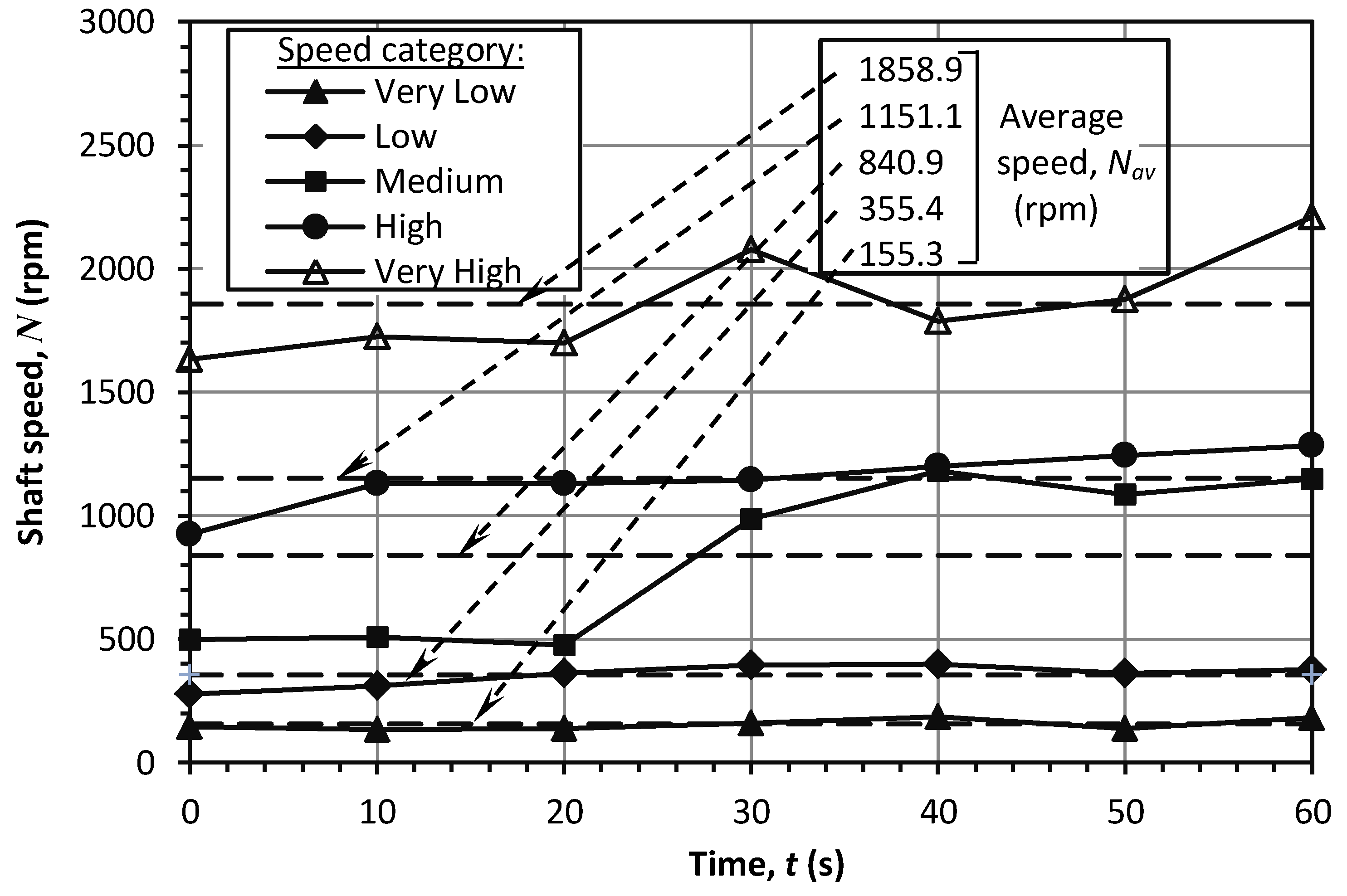
The kinetic energy of the wind is converted to rotational energy by momentum transfer via the turbine blades. The variation in the speed of the rotor shaft (N) with time is shown in Figure 4. As observed, the measured shaft speed varied in the range of 100 rpm ≤ N ≤ 2200 rpm, while the average speeds varied as 155 rpm < Nav < 1859 rpm. For very-low-, low-, and high-speed categories, the variation in the instantaneous speeds was marginal, whereas, for the medium- and very-high-speed categories, the variation was significantly high. Such observation was possibly due to the fact that the wind speed emerging from the pedestal fan might have become irregular at its peak speed due to several reasons including improper fan blade alignment, fan shaft eccentricity, etc.

4.2. Power Generation

The rotational energy produced at the rotor hub is utilized to generate electricity by means of the electrical components of the WT described above. The AC power output variations at different speeds are shown in Figure 5.
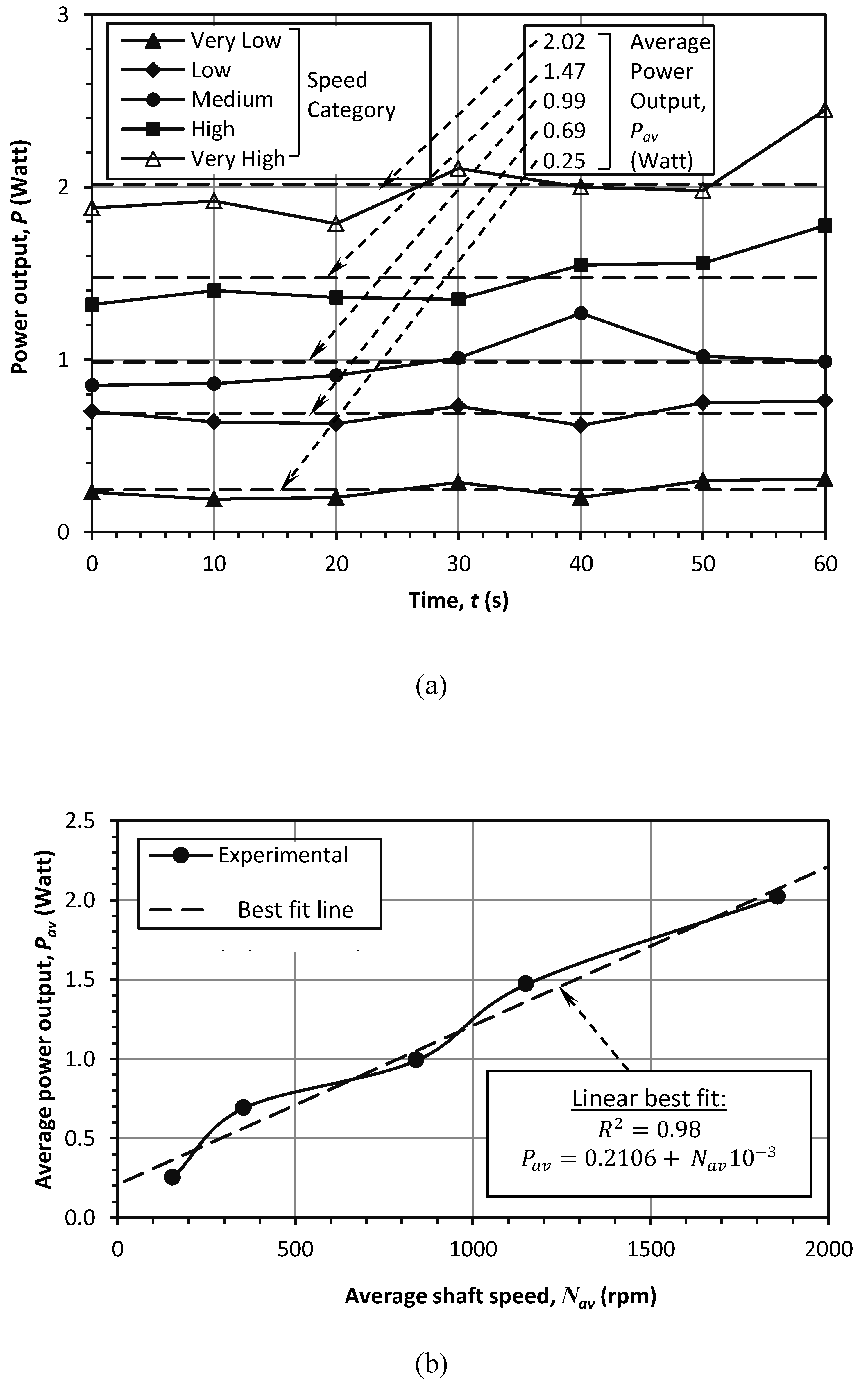
The variation in instantaneous power output (P) with time (t) for different speed categories is shown in Figure 5a. It is observed that the ranges of variation in the instantaneous and average power outputs were 0.19 W ≤ P ≤ 2.45 W and 0.25 W ≤ Pav ≤ 2.02 W, respectively. Furthermore, the patterns of variation were random, except for the very low and low speeds.
Figure 5b depicts the variation in average AC power output (Pav) with average shaft speed (Nav). As observed, the Pav increases fairly linearly with Nav, with the best fit line having a determination coefficient of R2 = 0.98. Moreover, for the given average shaft speed range of 155 rpm < Nav < 1859 rpm, the parameter Pav varied in the range of 0.25 W ≤ Pav ≤ 2.02 W.
The AC and DC power output voltages have been studied with shaft speed. The instantaneous AC and DC voltages (VAC and VDC) have been plotted against time (t) in Figure 6a,b, respectively. The ranges of variation were found to be 29 mV ≤ P ≤ 91 mV and 2.8 mV ≤ P < 369 mV, respectively, for the two cases. For AC voltages, the curves were found to be almost flat, except for the very-high-speed category, which exhibited a random pattern of variation. On the other hand, in the case of DC voltage, the curves were flat with negligibly small values in the case of the first three speed categories, unlike the high and very high speeds, which demonstrated random variation.
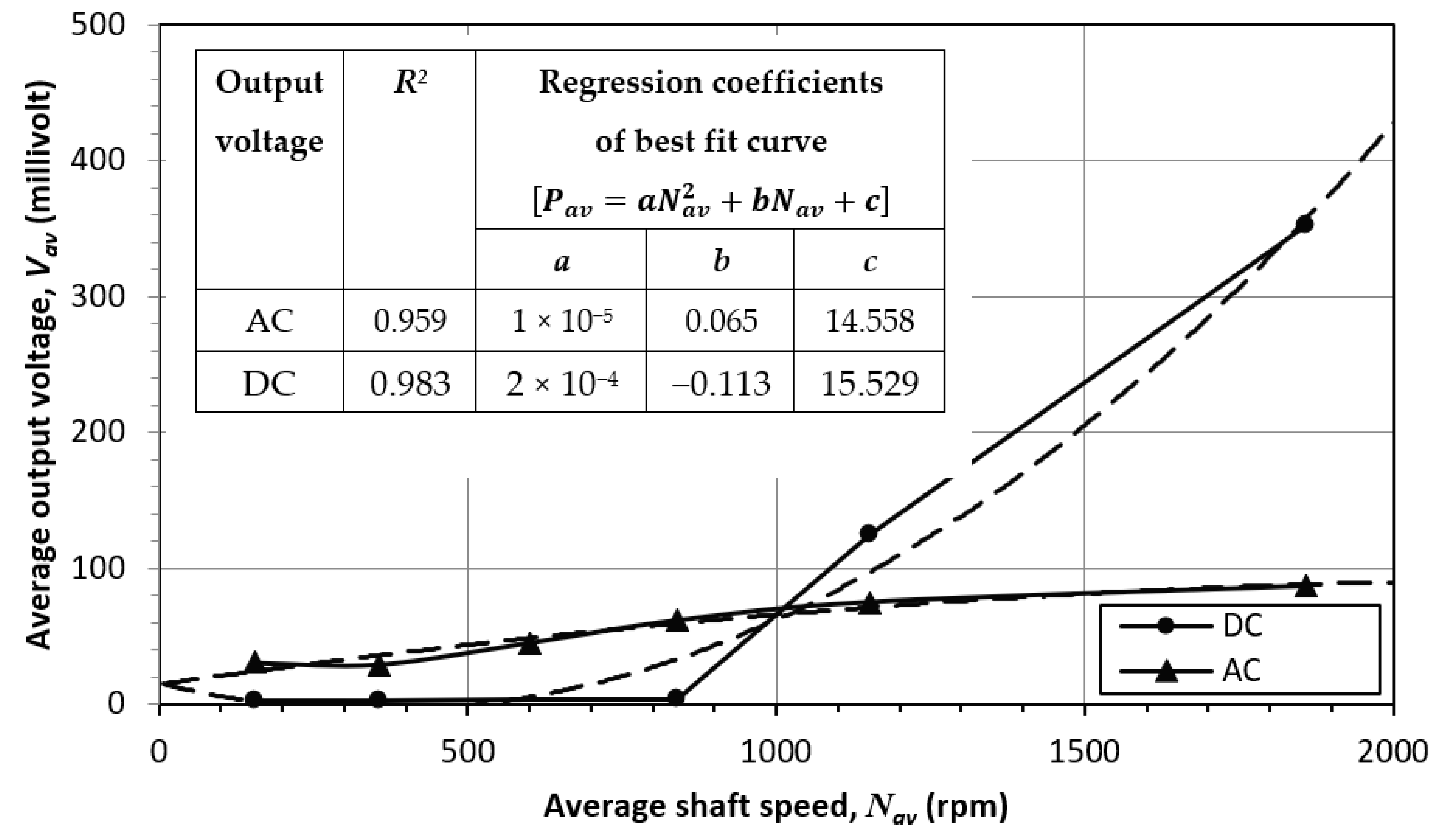
The plots between average voltage and average shaft speed are shown in Figure 7. It is found that for the given average shaft speed range of 155 rpm < Nav < 1859 rpm, the AC and DC average voltages varied in the ranges of 30 mV < Vav < 87 mV and 2.9 mV ≤ Vav < 353 mV, respectively. In both cases, the best-fit curves were found to be parabolic, with the correlation given by:
P a v = a N a v 2 + b N a v + c
where the appropriate values of the coefficients a, b, and c are given in Figure 7. The values of the determination coefficient (R2) were 0.959 and 0.983 for AC and DC voltages, respectively. However, in the former case, the slope of the regression curve was found to be descending, whereas, for the latter case, the observation was the opposite.

4.3. Vibration Analysis

Due to the rotation of the shaft as well as momentum transfer during blade–wind interaction, significant vibration is produced at the tower shaft. Such vibration is likely to be transmitted downwards to the base and foundation, thereby necessitating the appropriate analysis and quantification of the vibration pattern so as to enable appropriate structural and foundation design [44]. With this viewpoint, the current study was carried out.
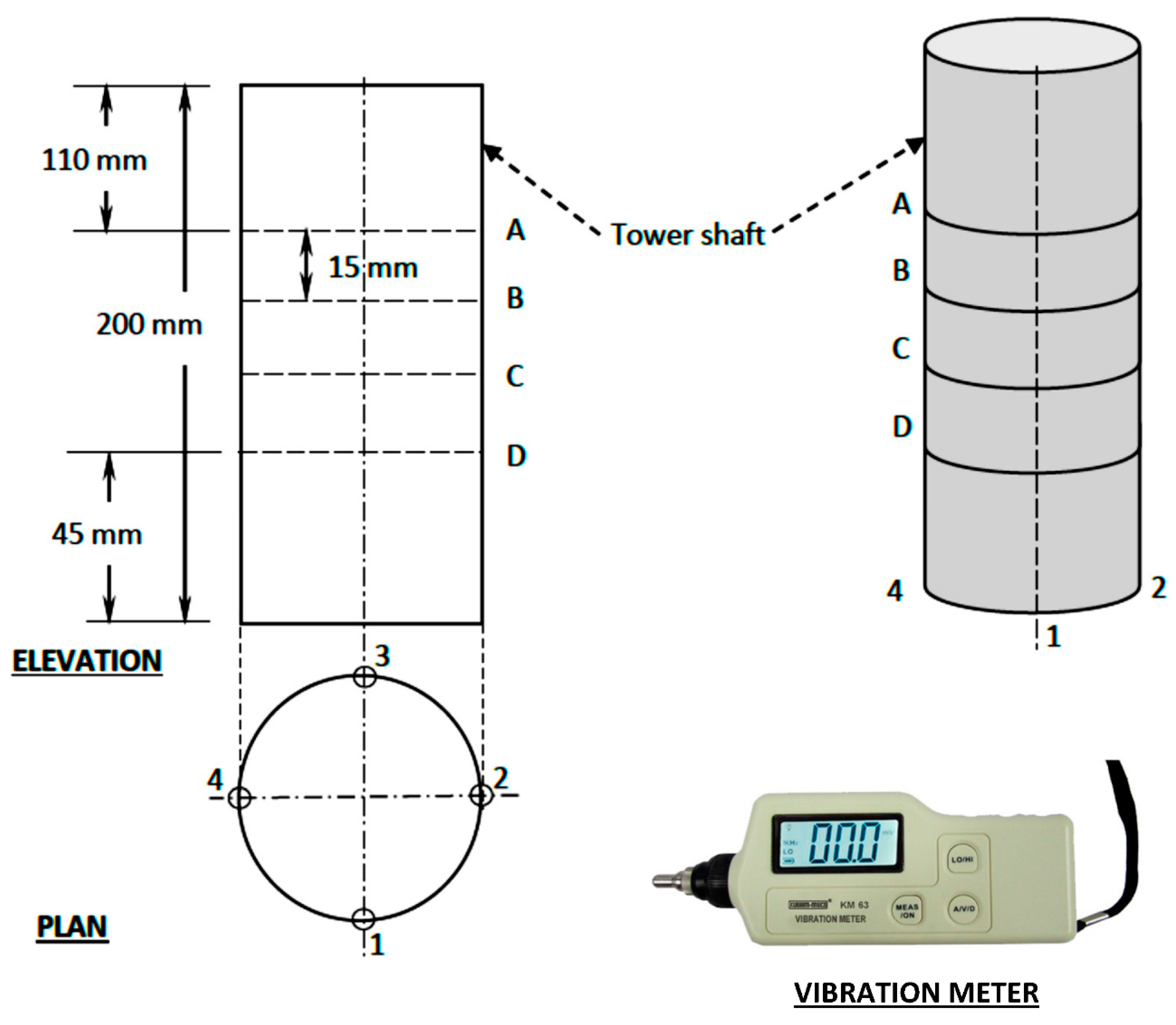
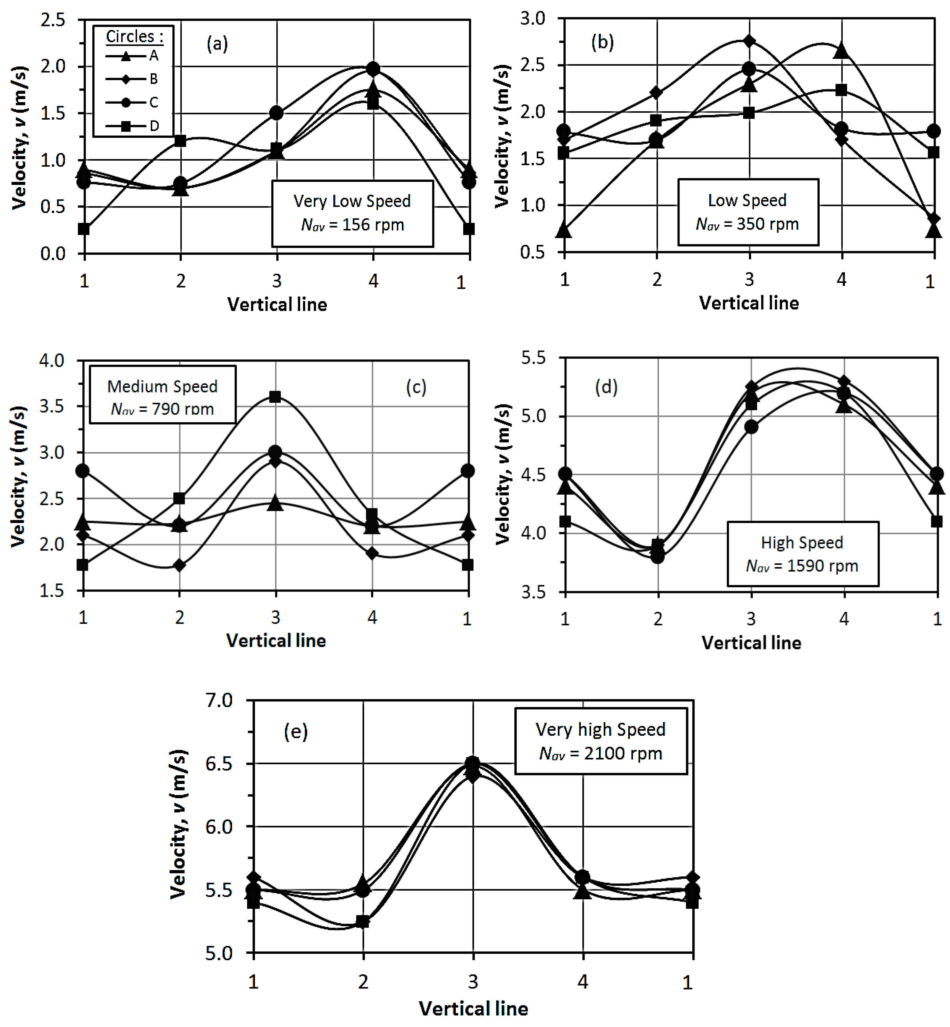
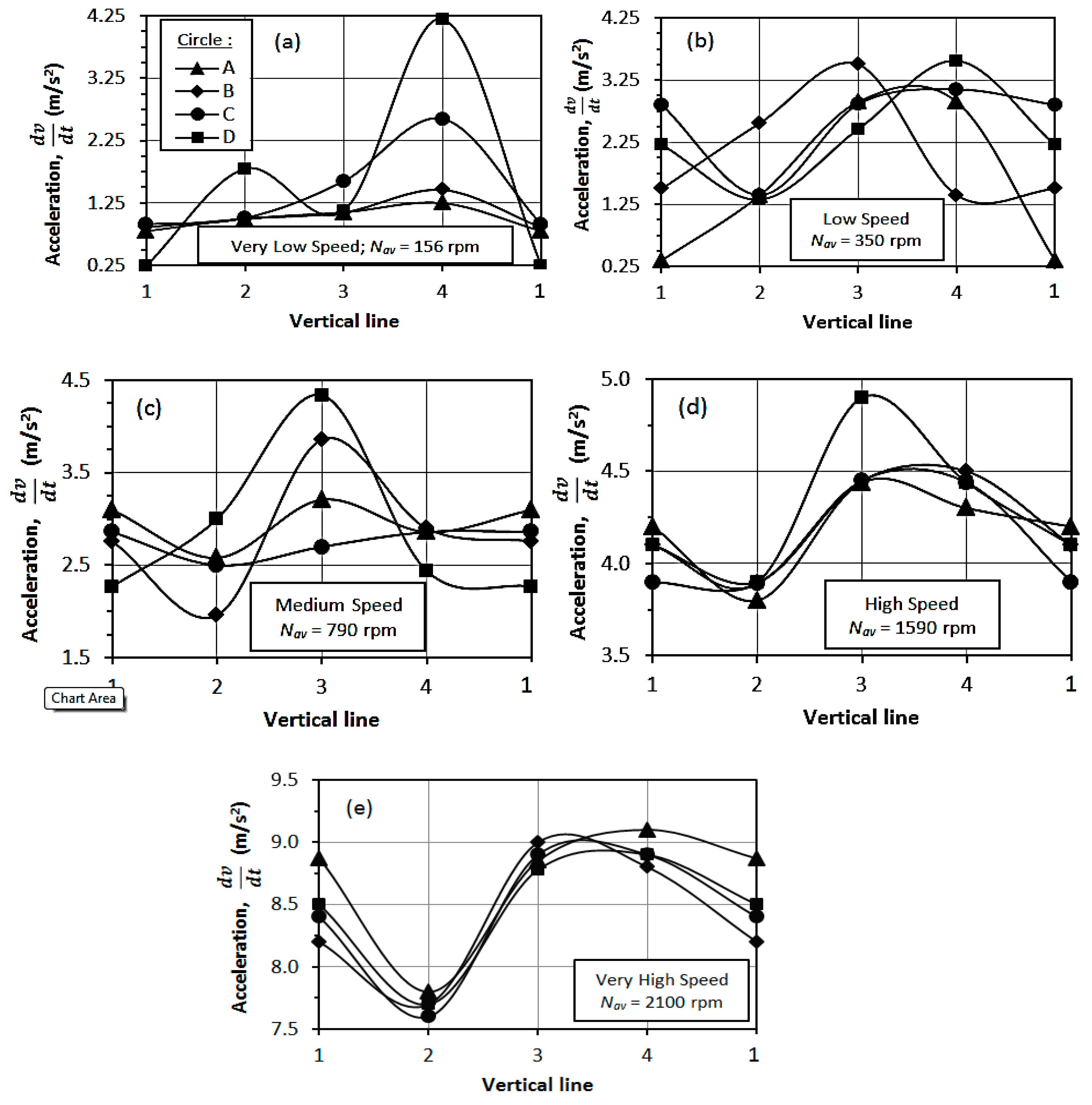
It is expected that the vibration is severe at the ball bearing’s location and is lesser in the vicinity of the base due to fixity. The ball bearing is located inside the tower shaft at a vertical distance of 110 mm below the top. Hence, four horizontal circles are drawn on the surface of the tower shaft using a marker, namely A, B, C, and D, as shown in Figure 8. Similarly, four vertical lines are also drawn on the shaft, numbered 1, 2, 3, and 4. The vibration was measured at each of the 16 points of intersection between the circles and the lines, the critical parameters being the peak values of horizontal displacement (δ), velocity (v), acceleration d v d t , and frequency (f). The details of the tests are given in Table 2.
The vibration measurements were conducted by means of an industry-standard vibration meter with a digital display facility. The range of vibration varies greatly from operation to operation. In a standard application of a 50 g range, the sensitivity of a typical vibration sensor is 100 mV/g, while in low vibration applications of a 10 g range, the sensitivity is 500 mV/G [45,46]. The units measured were displacement, velocity, and acceleration. In the current study, a piezoelectric ceramic accelerometer (shear-type) was used for the vibration measurement. For the particular type of vibration meter, the specific ranges of the measured peak values of the parameters, viz., displacement, velocity, and acceleration were: 0.001 ~ 1.999 mm, 0.1 ~ 199.9 m/s, and 0.1 ~ 199.9 m/s2, respectively. The measurement accuracy was: ± (5% + 2 digits). Moreover, the frequency was calculated indirectly from the measured values of the above parameters utilizing a calibration chart provided by the manufacturer. In each case, the frequency was evaluated from a vibration conversion chart given by the manufacturer.
The maximum value of a specific vibration parameter at a specified shaft speed at a specific circle was estimated from the plotted parameter. This maximum value was thereafter plotted depth-wise to estimate the relevant optimum value at the specified speed. This will ensure ascertaining adequate design values of the vibration parameters.
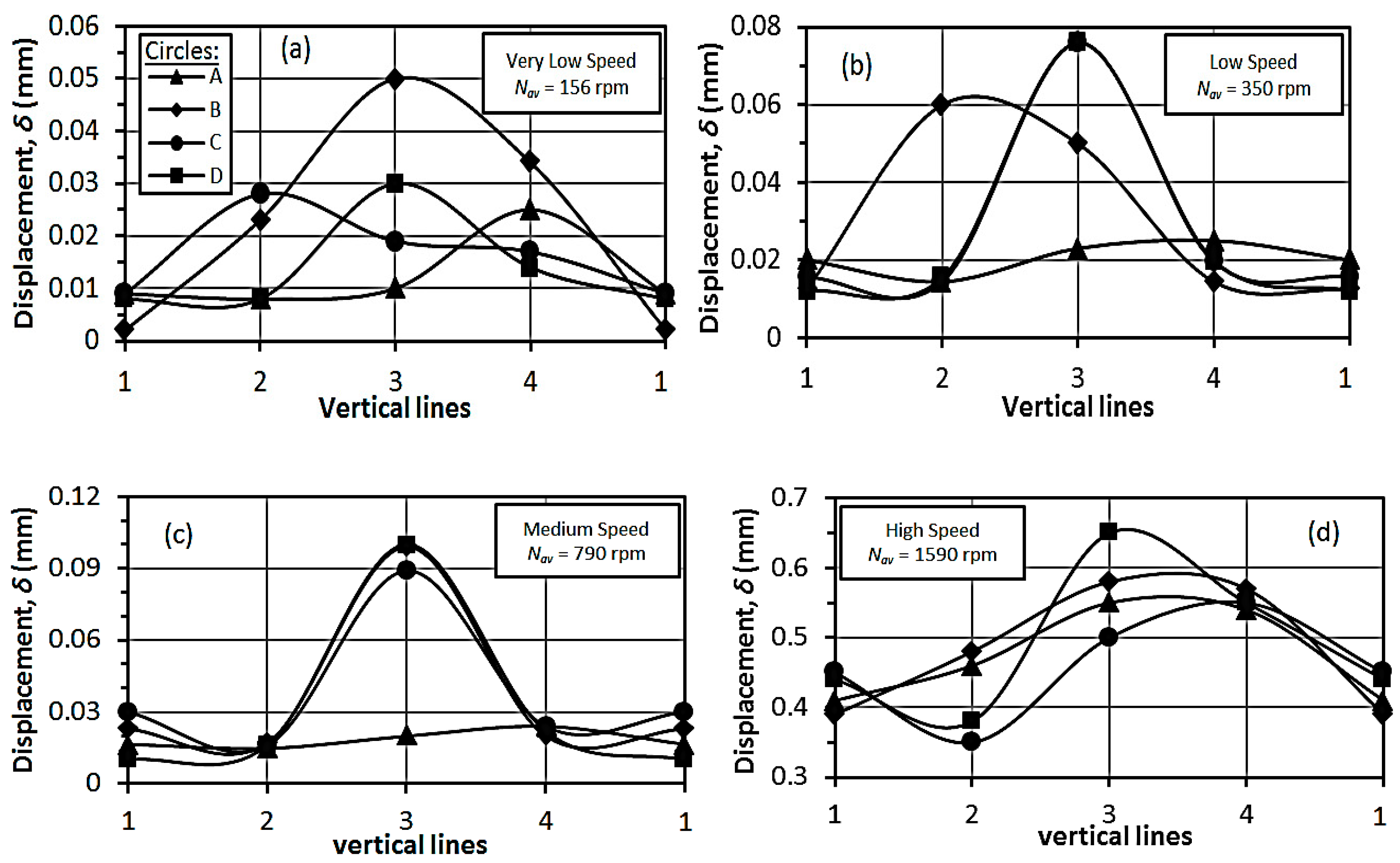
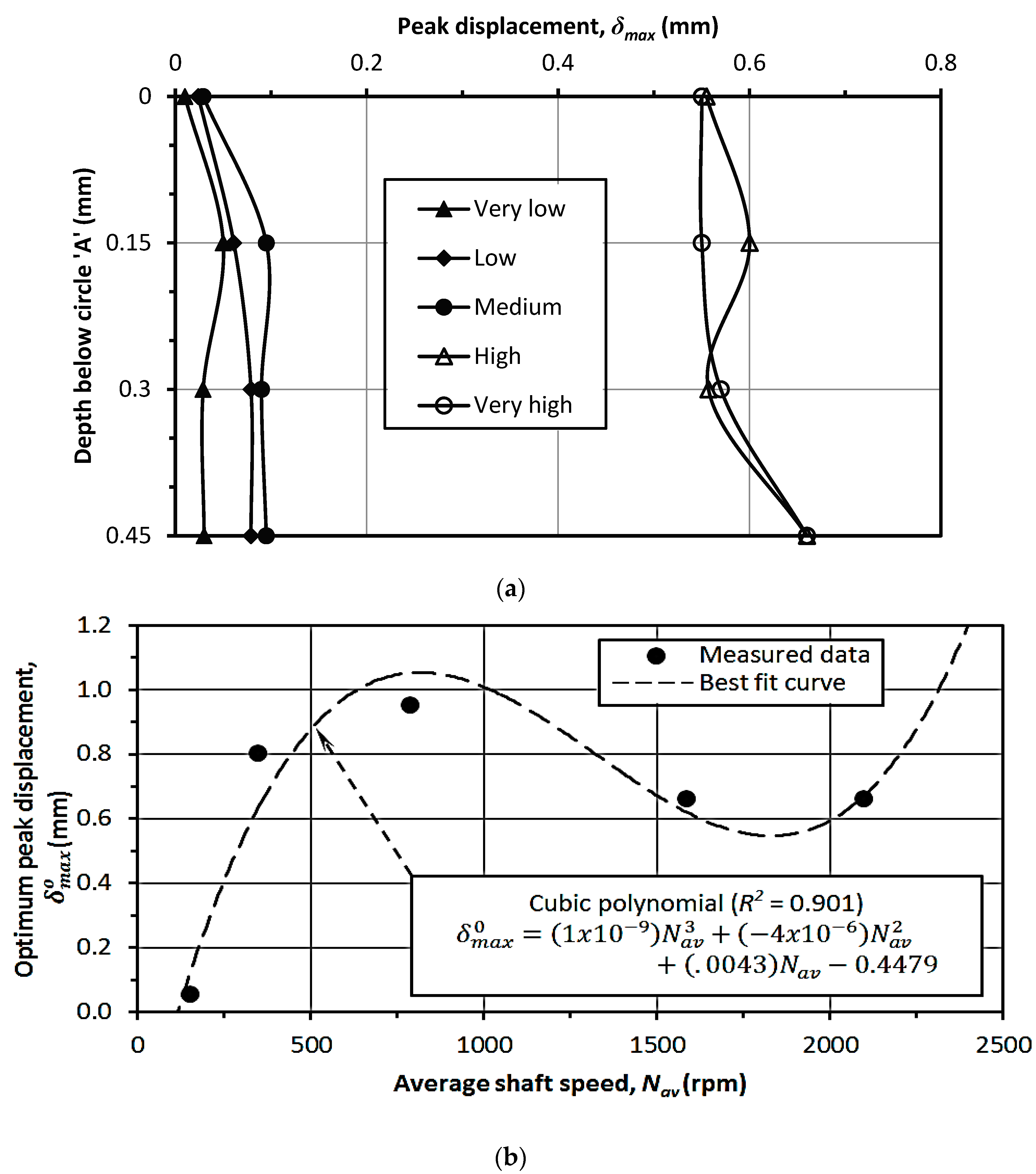
The plots depicting peak horizontal displacements of the tower shaft (δ) on the individual circles at different vertical lines are given in Figure 9. From the resulting curves, the maximum values of displacement (δmax) were estimated. Figure 10a portrays the depth-wise variation δmax at different shaft speeds, which was utilized to estimate the optimized value of maximum peak displacement ( δ m a x o ). The variation in δ m a x o with average shaft speed (Nav) is shown in Figure 10b. As observed, the pattern of variation is irregular, with the best-fit curve as a cubic polynomial (R2 = 0.901).
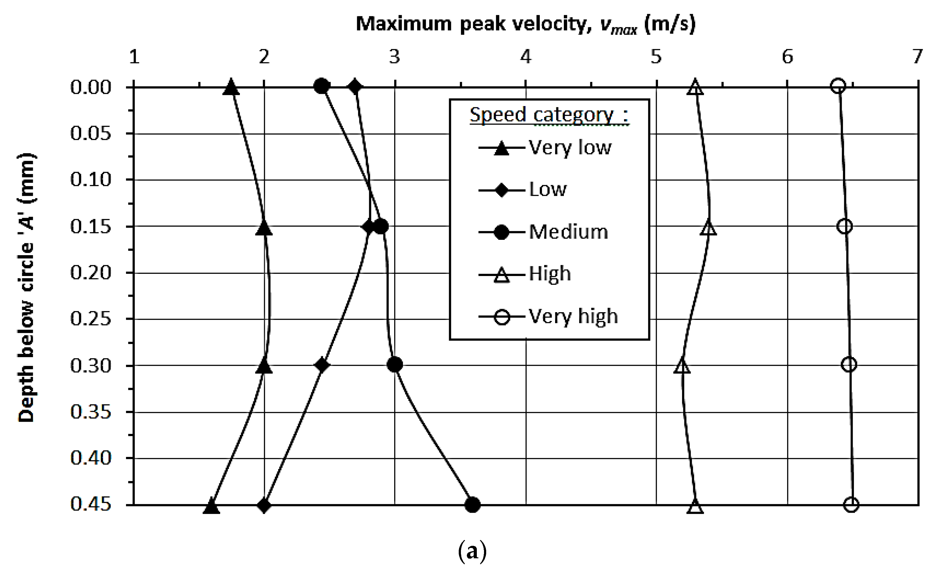
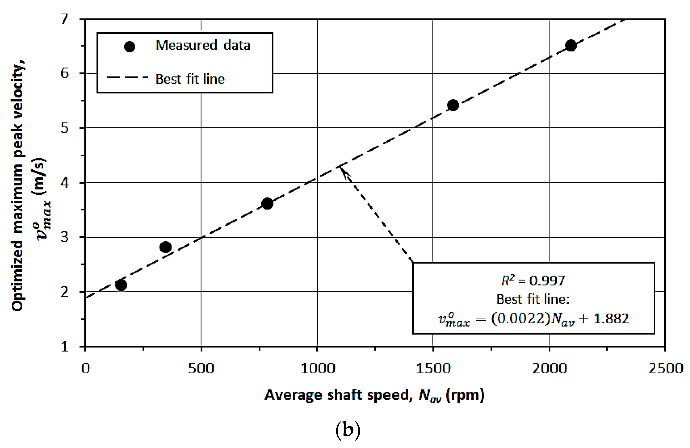
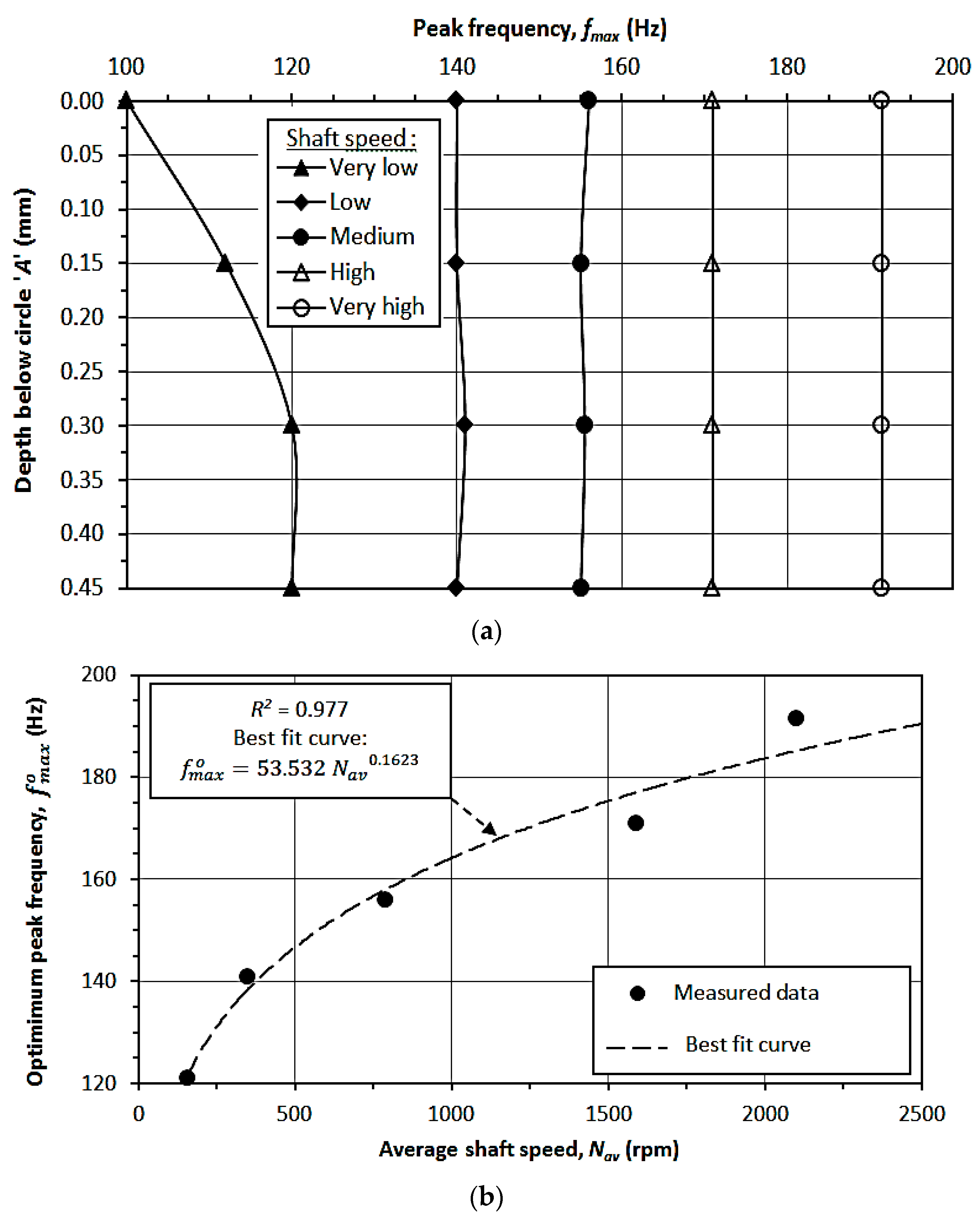
Similar graphical representations were plotted in the cases of the other vibration parameters such as v, d v d t , and f, as presented in Figure 11, Figure 12, Figure 13, Figure 14, Figure 15 and Figure 16, respectively. The correlations of the best-fit curves were found to be as follows:
δ m a x 0 = 1 × 10 9 N a v 3 + 4 × 10 6 N a v 2 + 0.0043 N a v 0.4479
  v m a x o = 0.0022 N a v + 1.882
d v d t m a x o = 3 × 10 6 N a v 2 + 0.0037 N a v + 4.8171
f m a x o = 53.532   N a v 0.1623
where δ m a x 0 ,   v m a x o , d v d t m a x o , and f m a x o are the optimized maximum peak horizontal vibration parameters, viz., displacement, velocity, acceleration, and frequency, respectively, and Nav is the average shaft speed. The above correlations are significant in terms of their specific applications for the design of the tower shaft, base, and foundation against the induced vibration.
The graphs in Figure 9, Figure 11, Figure 13 and Figure 15 were plotted to determine the optimum values of the peak vibration parameters, viz., displacement, velocity, acceleration, and frequency, respectively, for different categories of the average angular velocities of the tower shaft. These optimum values of vibration parameters are plotted against depth along the tower shaft, so as to determine their maximum values, in Figure 10a, Figure 12a, Figure 14a and Figure 16a respectively. These maximum values are plotted against the average angular velocities of the tower shaft in Figure 10b, Figure 12b, Figure 14b and Figure 16b respectively, and various regression correlations were obtained. This procedure demonstrates a guideline about the procedure that may be followed to carry out a complete vibration analysis in a full-scale wind turbine shaft in reality.

5. Application

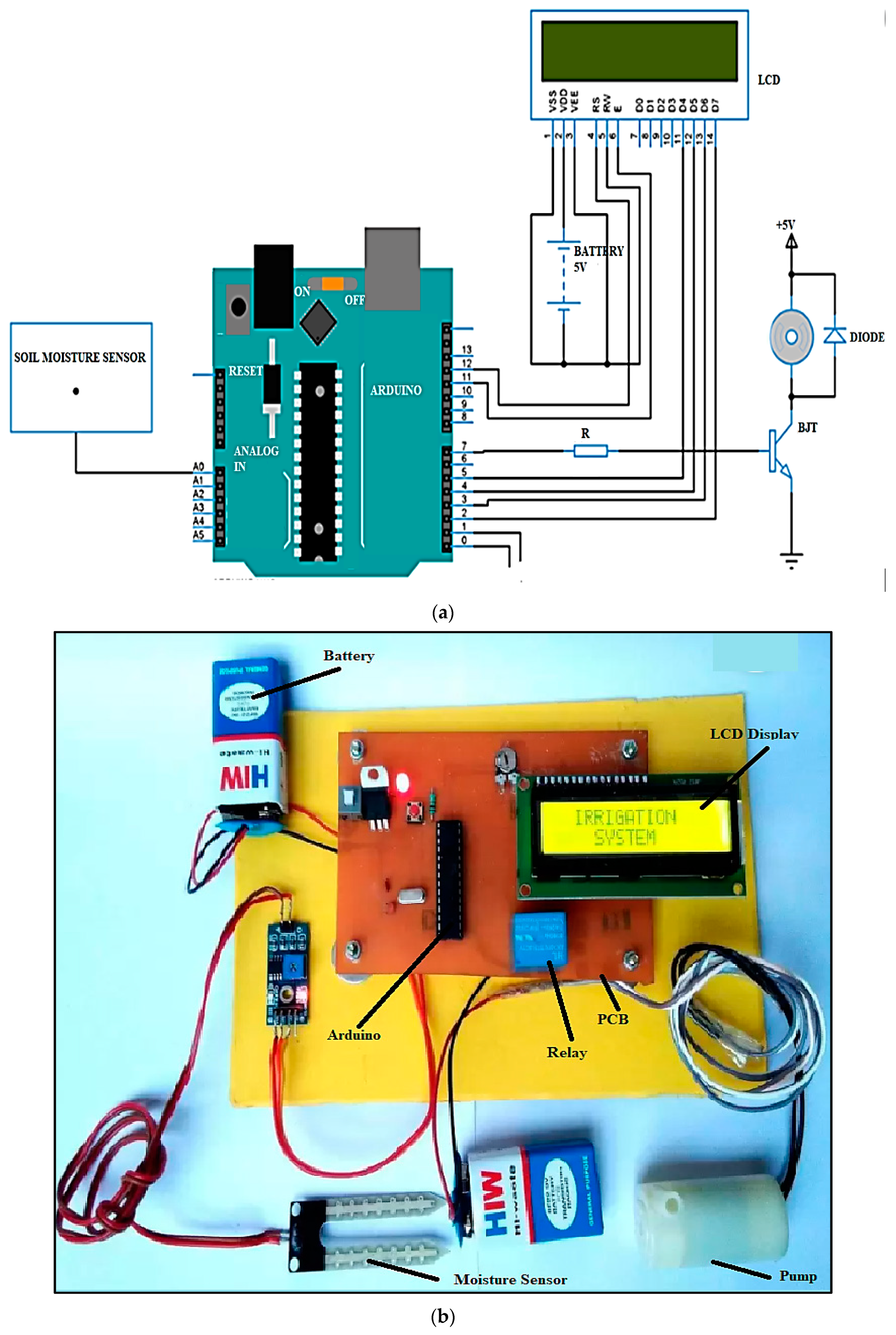
An electronically controlled automated drip irrigation system was designed and developed by the authors; the details have been presented elsewhere [47]. The equipment was tested using the output power generated by the wind turbine and a relevant performance analysis was conducted.

5.1. Description

The equipment was fabricated with an Arduino-based input–output board with an integrated development environment to implement an appropriate processing language, combining the Atmel microcontroller family with standard hardware with an inbuilt boot loader for plug-and-play embedded programming. The developed system is associated with the following components: microcontroller, 16 MHz crystal, soil moisture sensor, voltage regulator, 22 pf capacitor, 10 k resistance, variable resistor, relay LCD display, and DC water pump. The drip irrigation equipment derives power from the storage battery of the WT to pump water from a reservoir whenever the soil moisture falls below a threshold limit and deliver it to the soil. The circuit diagram of the developed system and its photographic view is presented in Figure 17.

5.2. Performance Analysis

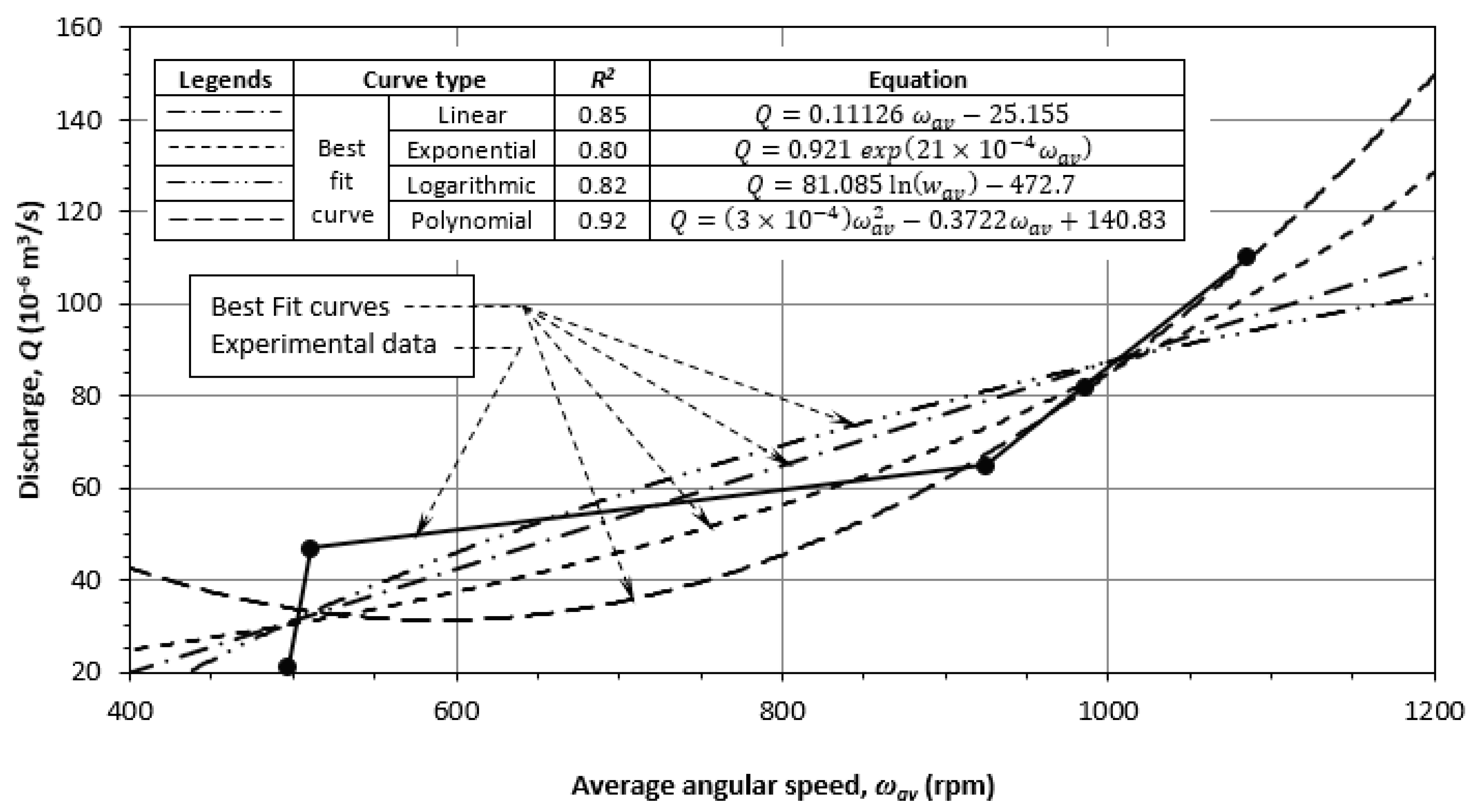
To conduct the performance study, the soil moisture sensor was dripped into a dry soil mass and the discharge from the system initiated by the pump was measured for different shaft speeds of the WT. Figure 18 portrays the variation in pump discharge (Q) with average shaft speed (Nav). The discharge was found to increase with average shaft speed, following an irregular pattern. Several best-fit curves (viz., linear, polynomial, logarithmic, and exponential) were also included, and it was found that the polynomial function of the order of 3 was close to the observed data (R2 = 0.92).

6. Theoretical Analysis

A numerical model pertaining to the wind flow and analytical modeling for power generation in the WT was developed, as described in this section.

6.1. Wind Flow Modeling

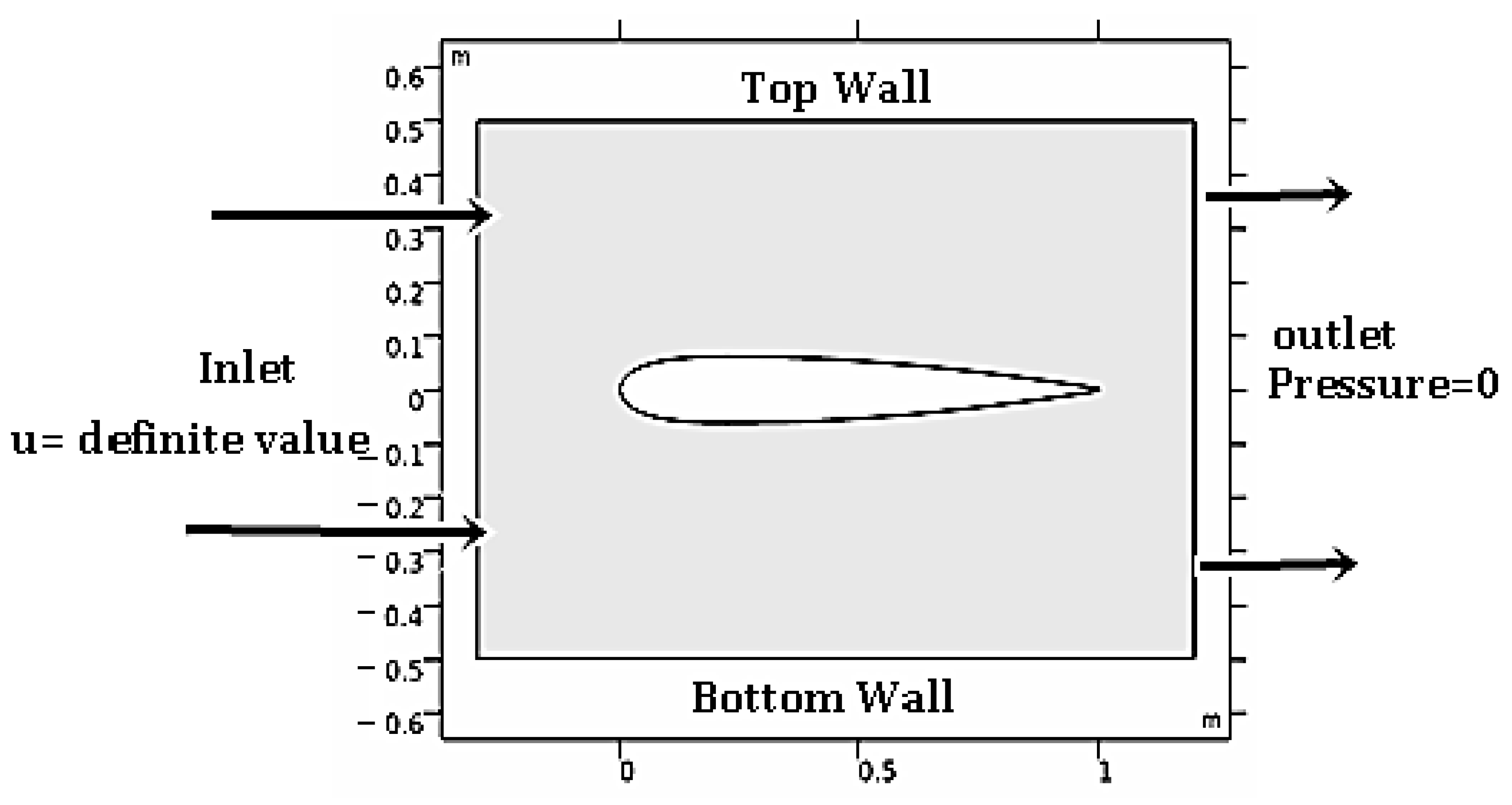
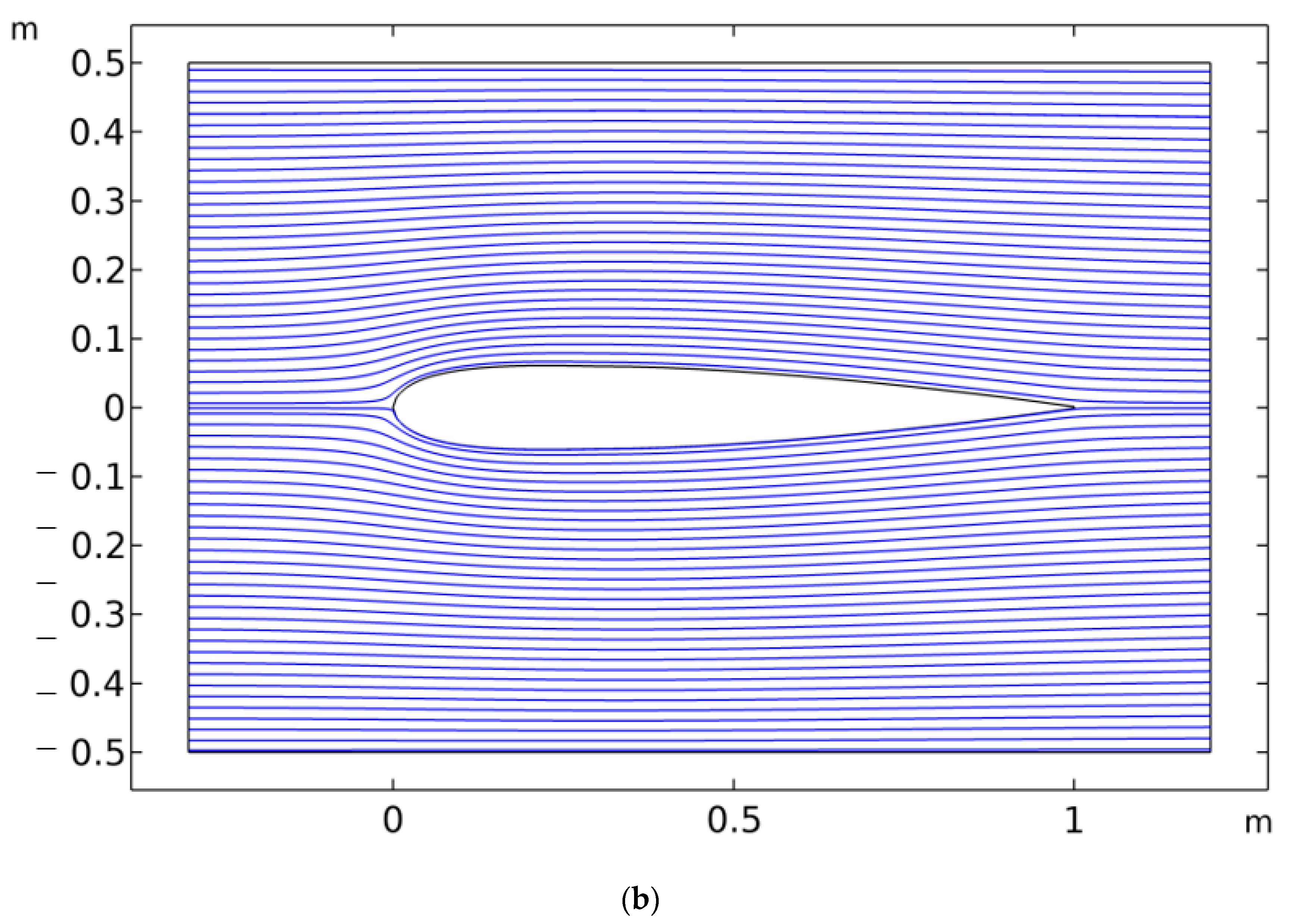
The steady-state velocity and pressure fields were simulated using the COMSOL CFDTM (version 5.6) for a small-scale model vertical-axis wind turbine. To bring parity in the numerical analysis, comparative studies of inlet wind speeds representing both laminar and chaotic air flows were conducted, with values of 5 m/s and 20 m/s representing laminar and turbulent flows, respectively. The 2D geometry of the NACA 0012 airfoil was developed using the COMSOL Multi-Physics graphics user interface, which was then placed in a rectangle area with a size of 1.5 m in length and 1 m in width, representing a section of a wind tunnel (see Figure 19). The top and bottom edges of the rectangular area, as well as the surface of the airfoil, were set as wall boundary conditions, while the left and right edges were set as inlets, with uniform and horizontal wind flow. The pressure at the outlet was taken as zero.
The laminar flow regime was governed by the following differential equations representing the conservation of momentum and energy:
ρ t + . ρ u = 0
ρ u t + ρ ( u . ) u = . [ p + τ ] + F
where ρ is the air density; u is the velocity vector; p is pressure; τ is the viscous stress tensor; F is the volume force vector; and ‘ . ’ denotes a contraction between two tensors.
In the case of turbulent flow, on the other hand, turbulent viscosity was modeled as follows:
μ T = ρ C μ k 2 ε
where Cμ is a model constant. The transport equation for turbulent kinetic energy k is represented by:
ρ k t + ρ u . k = . μ + μ T σ k k + N k ρ ε
N k = μ T u : u + ( u ) T ) 2 3 . u 2 2 3 ρ k . u
The transport equation for the turbulent dissipation rate ε is further modeled as
ρ ε t + ρ u . ε = . μ + μ T σ ε ε + C ε 1 ε k N k C ε 2 ε 2 k
where Nk, Cε1, and Cε2 are model constants. The parameters in the above equations were determined from experimental results and the values are listed in Table 3, adopted from similar computations carried out by Ma et al. [48].
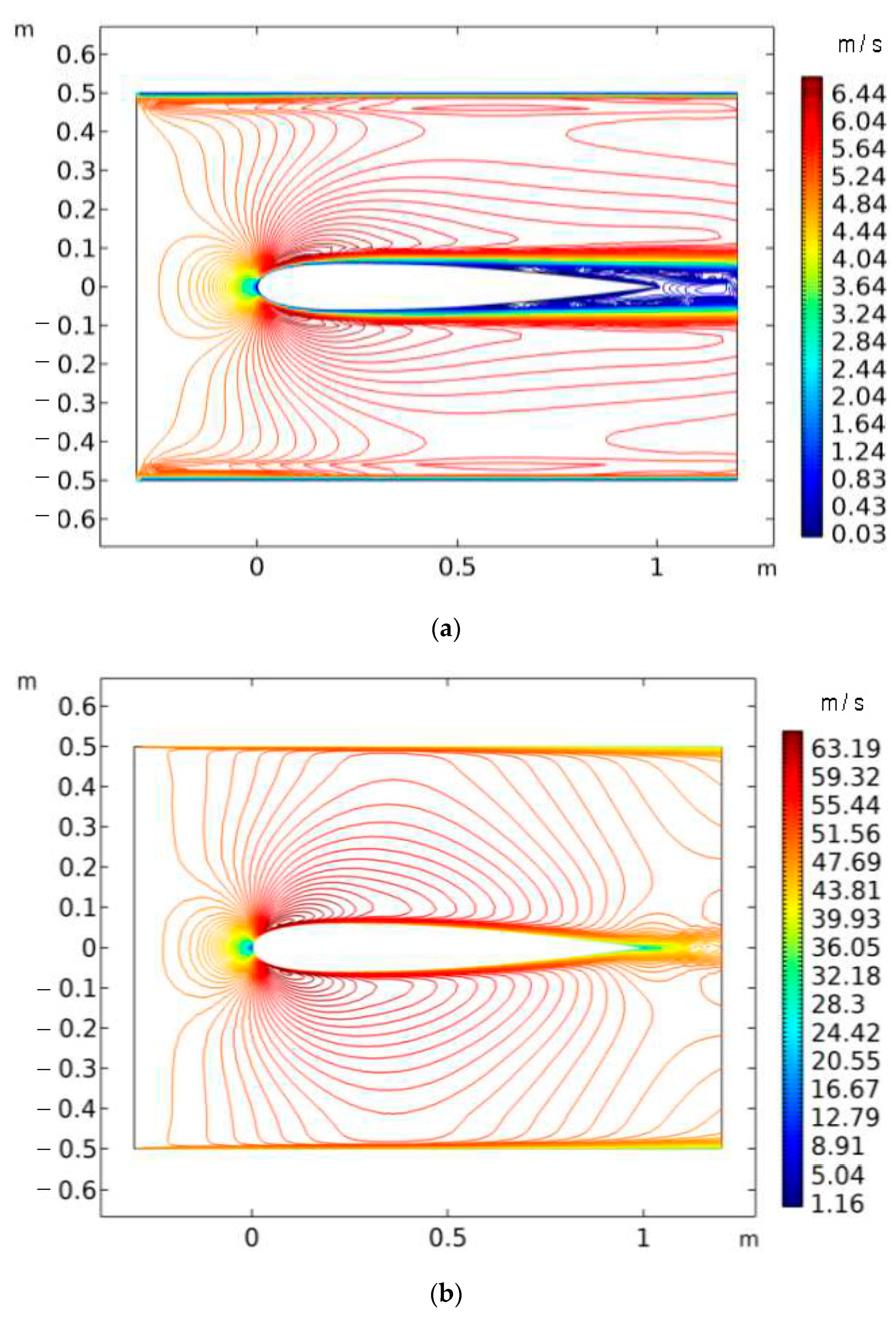
The velocity contour profiles of an airfoil positioned at a zero angle of attack for low and high inlet wind speeds (i.e., 5 m/s and 20 m/s, respectively) are shown in Figure 20. The maximum air-flow speeds were observed to reach 6.44 m/s and 63.19 m/s for the low and high inlet wind speeds, respectively, the maximum values occurring in the vicinity of the leading edge of the airfoil. On the other hand, the minimum air-flow speed for low inlet wind speed was found to be 0.03 m/s with its location near the bottom side of the airfoil. The flow increased to a large extent on the leading and backward sections of the airfoil for high inlet wind speed. In both cases, the tip of the airfoil recorded less speed, as per the velocity profiles.
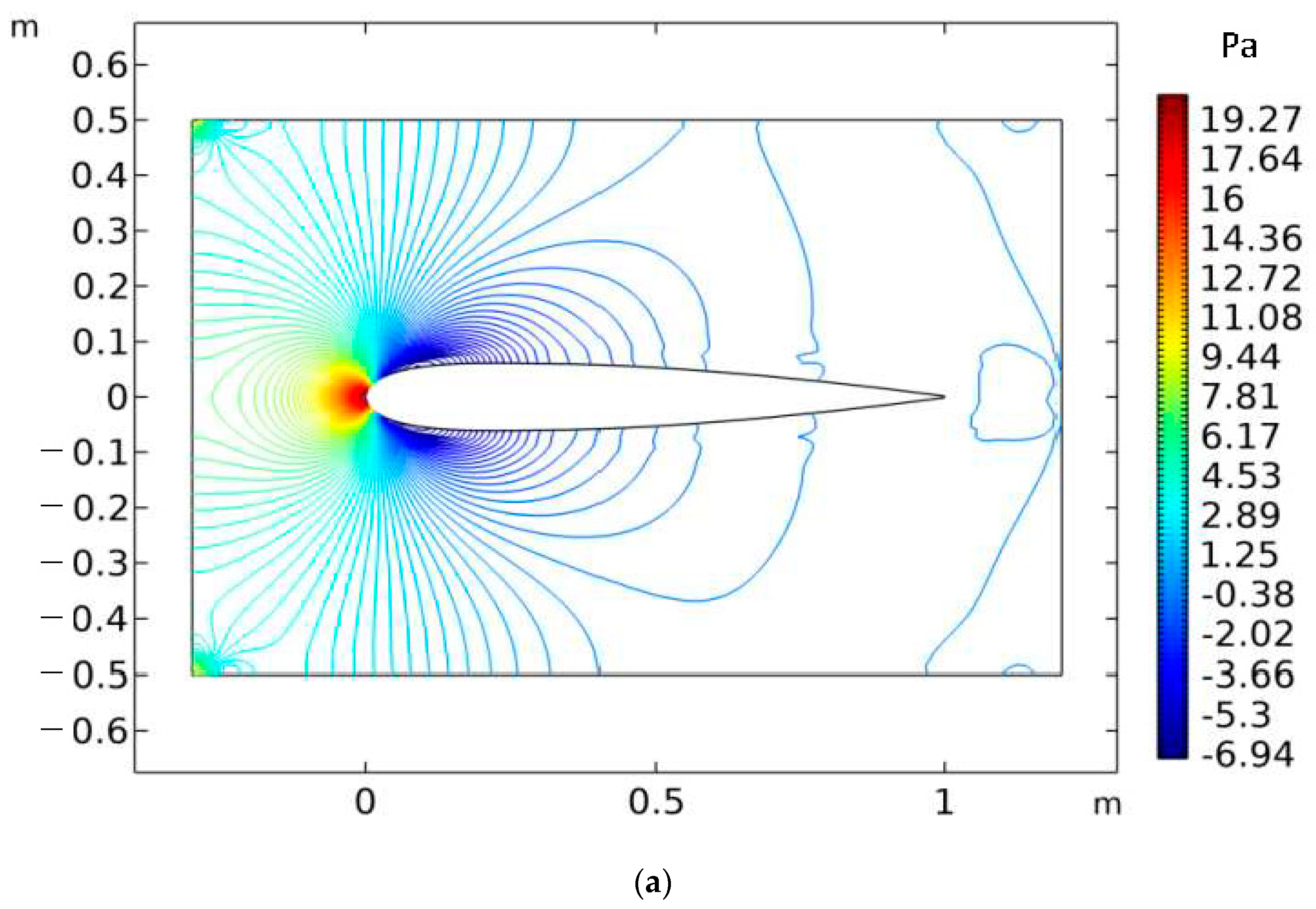
The pressure profiles of the airfoil are shown in Figure 21. The peak pressure was observed to occur near the leading edge on top of the airfoil where the lowest wind-flow speed exists. The lowest pressure was found near the leading edge on the bottom of the airfoil, with the highest wind-flow speed. The value of peak pressure ranged from −6.94 to 19.27 Pa and 1.1 × 10³ to 1.7 × 10³ Pa for low and high inlet wind speeds, respectively. Both velocity and pressure at the bottom of the airfoil remained fairly constant, with the exception at the leading edge.
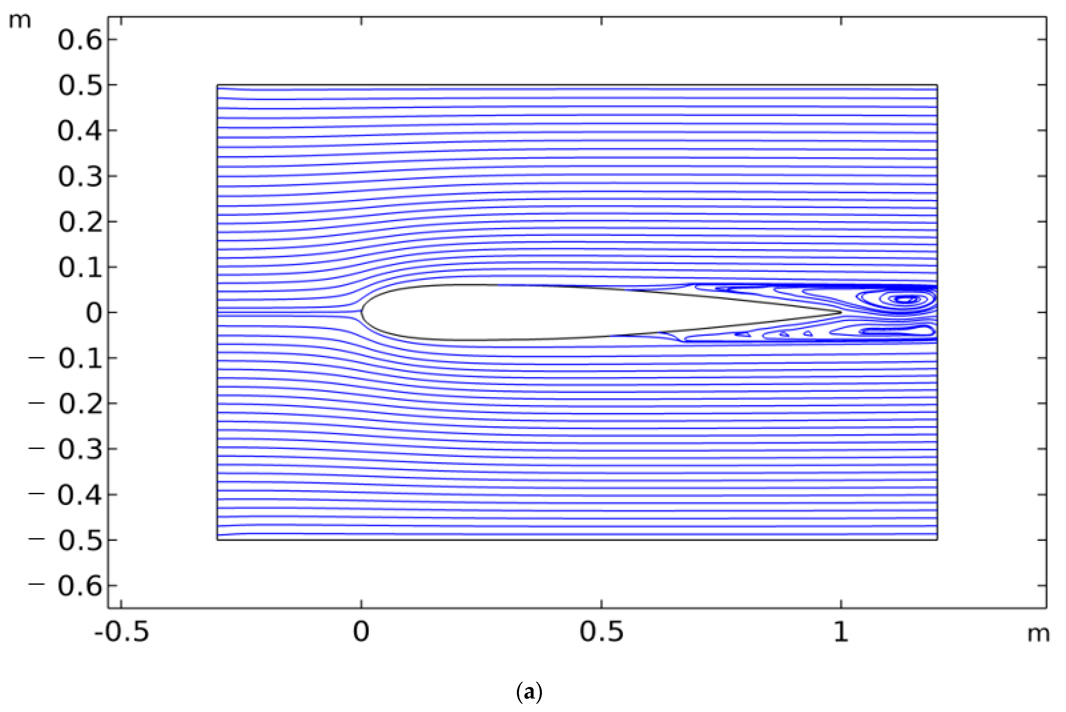
The streamline profiles of the airfoil are shown in Figure 22. The streamlines were fairly smooth for high inlet wind speed, whereas a flow separation took place in the case of low inlet wind speed for the backward side of the airfoil, possibly due to the formation of vortex motion.

6.2. Power Efficiency

Modifying Equation (2) above, the input wind power for a VAWT may be written by [49,50]:
P = 1 2 ρ 2 r l π N a v 30 r λ 3
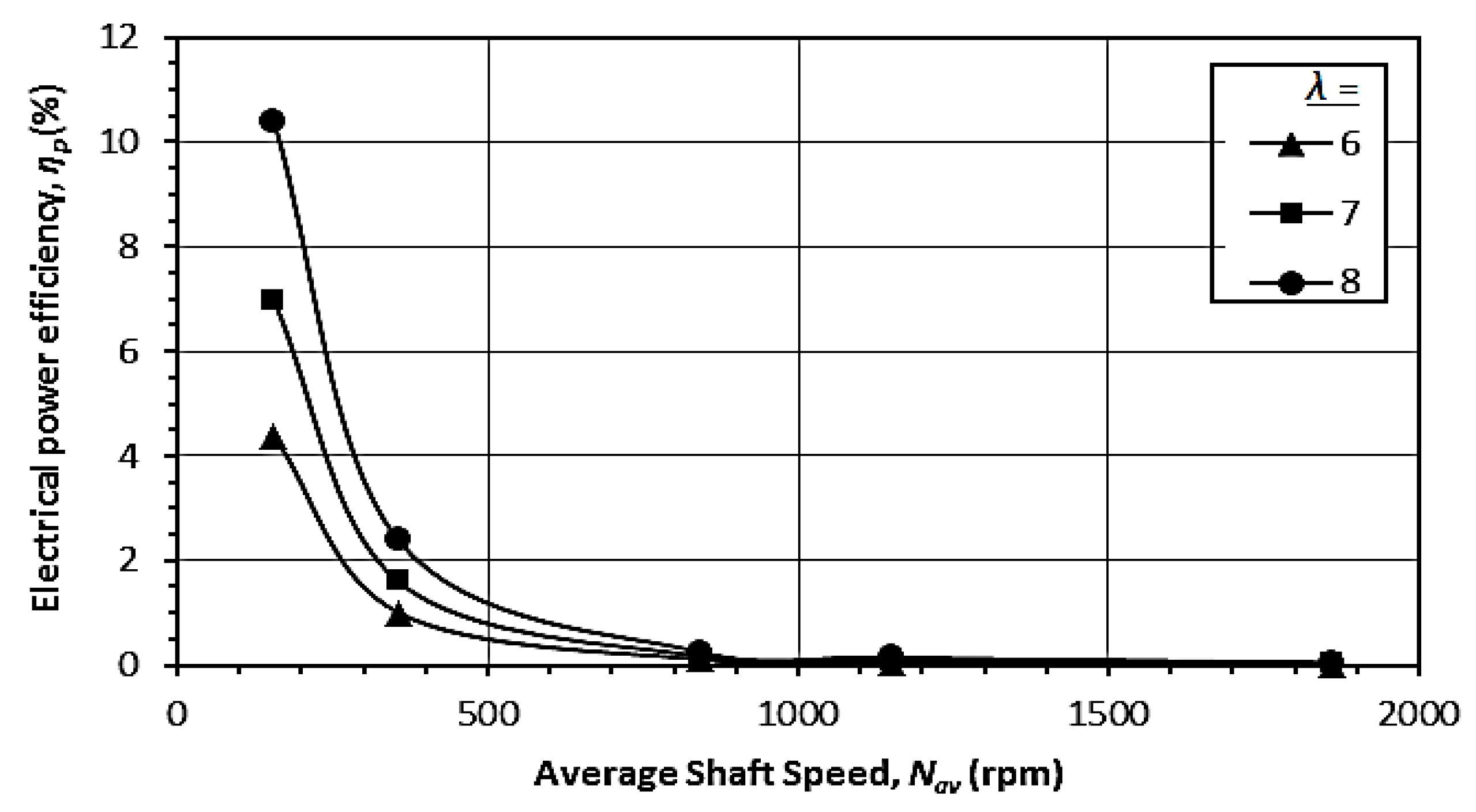
where r is the effective radius, i.e., the distance of the blade’s center-line from the axis of the rotor hub; l is the length of the blades; and λ is the tip speed ratio, defined as the ratio of the tip speed of the blade to the wind speed, whose value usually varies in the range of 6–8 [51].
If Pav is the measured average power output from the WT, the power efficiency η p is given as
η p = P a v 1 2 ρ 2 r l π N a v 30 r λ 3   × 100 %
With the input parameters given in Table 4, the theoretical power efficiency variation with the average angular speed of the rotor hub has been presented in Figure 23. As observed, the electrical power efficiency decreases curvilinearly following ascending slopes with increasing shaft speed. For the given range of average shaft speed, the electrical power efficiency was observed to vary in the range of 0.02–10.4%. The curves reduced quite sharply for Nav < 350 rpm and moderately for 350 rpm < Nav < 850 rpm. For Nav > 850 rpm, the efficiency η p was found to be negligibly small. Such observation is possibly due to the fact that higher wind speed produced significant input wind power compared to a relatively small magnitude of electrical power output.

7. Summary and Conclusions

7.1. Summary

A small-scale prototype vertical-axis wind turbine was fabricated and installed in the laboratory and extensive parametric studies were performed, followed by theoretical analyses including numerical and analytical modeling.

7.2. Conclusions

The study revealed that the average electrical power output increased fairly linearly with the average shaft speed. The average output voltage (both AC and DC) increased curvilinearly with increasing shaft speed, the best-fit curves exhibiting polynomials of the order of 2.
A vibration analysis of the tower shaft was conducted by measuring the peak values of the critical parameters, including displacement, velocity, acceleration, and frequency at selected points located at specific depths and circumferential distances on the shaft surface. Although the variations were observed to be random, the optimized maximum peak values of the parameters were observed to follow regular patterns with average shaft speeds. The best-fit curves for displacement, velocity, acceleration, and frequency were found to be cubic polynomial, linear, parabolic, and power series, respectively.
The finite element modeling was conducted to study the steady-state velocity and pressure fields simulated by the COMSOL CFDTM (version 5.6) for both laminar and turbulent flows. The numerical results indicated that the wind velocity increased to a large extent on leading and backward sections of the airfoil, while the tip of the airfoil exhibited less speed. The peak pressure took place near the leading edge on top of the airfoil, while the lowest pressure was found near the leading edge on its bottom. Both velocity and pressure at the bottom of the airfoil remained fairly unaltered except at the leading edge. The streamlines were smooth for turbulent flow, whereas flow separation occurred for laminar flow.
Analytical computation carried out to evaluate electrical power efficiency indicated a curvilinear reduction in efficiency with increasing shaft speed. The efficiency almost diminished for Nav > 850 rpm.

7.3. Novelty

Detailed parametric studies on small-scale vertical-axis wind turbines are rarely available, although their importance from the viewpoint of the appropriate design of full-scale wind turbines is undeniable. In this paper, the power generation and its efficiency for a wide range of wind speeds were analyzed. Moreover, an in-depth vibration analysis of the tower shaft through laboratory measurements followed by regression analysis was conducted. Moreover, a numerical model for wind flow studies was also performed. The research findings are expected to be of significant practical application as well as expose the scope for further research, as discussed below.

7.4. Limitations

In spite of the above-mentioned novelty of the entire investigation, it has a few inherent limitations as well, as described below:
  • The model wind turbine was supplied by the manufacturer. For a better study, the same could be designed and fabricated in-house with more instrumentations.
  • The optimum design of a wind turbine requires an adequate analysis of its foundation stability [53,54]. Moreover, offshore WTs should be analyzed against adverse ocean environments [55,56]. For long-term performance analysis, these factors should essentially be considered.

7.5. Future Research Directives

Relevant future research directives may be focused on the following:
  • Comparative studies on vertical- and horizontal-axis wind turbine performance analyses in terms of power generation efficiencies compared to installation and operational costs by means of small-scale models and full-scale field-based experiments.
  • More rigorous theoretical models (analytical and/or numerical) may be developed to study the correlations between the wind flow velocity and the rotational energy produced, associated with lift and drag force analyses.
  • Appropriate design recommendations for single and multiple turbines based on statistical and decision modeling concepts for optimal wind energy extraction might be significant for industrial uses [57].

Author Contributions

Conceptualization, S.B. and S.D.; methodology, S.B.; software, S.D.; validation, S.B., S.D. and D.S.; formal analysis, S.B.; investigation, S.B., S.D. and D.S.; resources, S.B. and S.D.; data curation, S.B., S.D. and D.S.; writing—original draft preparation, S.B.; writing—review and editing, S.B., S.D. and D.S.; visualization, S.B. and S.D.; supervision, S.B.; project administration, S.B. All authors have read and agreed to the published version of the manuscript.

Funding

This research received no external funding.

Institutional Review Board Statement

Not applicable.

Informed Consent Statement

Not applicable.

Data Availability Statement

All data are available in the manuscript.

Acknowledgments

The authors thankfully acknowledge the assistance received from Pradip Dey, Technical Officer, and Nepal Das, Technical Assistant of Elitte College of Engineering during the work. Financial assistance for this research was given by Pinnacle Education Trust, Kolkata, India.

Conflicts of Interest

The authors declare no conflict of interest.

Abbreviations

ASwept area of wind flow in turbine;
Cε1, Cε2, CμModel constants in finite element analysis;
d v d t m a x 0   Optimized maximum peak acceleration;
EtWind energy;
fPeak frequency of vibration in tower shaft;
fmaxMaximum peak frequency;
f m a x 0 Optimized maximum peak frequency;
FVolume force vector;
gGravitational acceleration;
kTurbulent kinetic energy;
lLength of blades;
NShaft speed;
NavAverage shaft speed;
NkModel constant in finite element analysis;
pWind pressure;
PWind power;
PavAverage power output;
QDischarge from drip irrigation equipment outlet;
RCoefficient of determination in regression analysis;
rEffective blade radius;
tTime;
uWind velocity vector;
vPeak velocity of tower shaft vibration;
vmaxMaximum peak velocity of tower shaft vibration;
v m a x 0 Optimized maximum peak velocity of tower shaft vibration;
VACAC voltage output;
VDCDC voltage output;
VavAverage voltage output;
δPeak displacement of tower shaft vibration;
δmaxMaximum peak displacement of tower shaft vibration;
δ m a x 0 Optimized maximum peak displacement of tower shaft vibration;
εTurbulent dissipation rate;
ηpElectrical power efficiency;
γWind unit weight;
λTip speed ratio;
μTTurbulent viscosity;
ρAir density;
τShear stress.

References

  1. Omar, E.; Haitham, A.R.; Frede, B. Renewable energy resources: Current status, future prospects and their enabling technology. Renew. Sustain. Energy Rev. 2014, 39, 748–764. [Google Scholar]
  2. Shahzad, U. The need for renewable energy sources. Int. J. Inf. Technol. Electr. Eng. 2015, 4, 16–19. [Google Scholar]
  3. Owusu, P.A.; Asumadu-Sarkodie, A. A review of renewable energy sources, sustainability issues and climate change mitigation. Cogent Eng. 2016, 3, 1167990. [Google Scholar] [CrossRef]
  4. Hosseini, S.M.; Kanagaraj, N.; Sadeghi, C.; Yousefi, H. Midpoint and endpoint impacts of electricity generation by renewable and nonrenewable technologies: A case study of Alberta, Canada. Renew. Energy 2022, 197, 22–39. [Google Scholar] [CrossRef]
  5. Enevoldsen, P.; Permien, F.-H.; Bakhtaoui, I.; von Krauland, A.-K.; Jacobson, M.Z.; Xydis, G.; Sovacool, B.K.; Valentine, S.V.; Luecht, D.; Oxley, G. How much wind power potential does Europe have? Examining European wind power potential with an enhanced socio-technical atlas. Energy Policy 2019, 132, 1092–1100. [Google Scholar] [CrossRef]
  6. Evans, A.; Strezov, V.; Evans, T. Assessment of sustainability indicators for renewable energy technologies. Renew. Sustain. Energy Rev. 2009, 13, 1082–1088. [Google Scholar] [CrossRef]
  7. Basack, S.; Goswami, G.; Dai, Z.-H.; Baruah, P. Failure-mechanism and design techniques of offshore wind turbine pile foundation: Review and research directions. Sustainability 2022, 14, 12666. [Google Scholar] [CrossRef]
  8. Cheng, M.; Zhu, Y. The state of the art of wind energy conversion systems and technologies: A review. Energy Convers. Manag. 2014, 88, 332. [Google Scholar] [CrossRef]
  9. Savenkov, M. On the truncated weibull distribution and its usefulness in evaluating potential wind (or wave) energy sites. Univ. J. Eng. Technol. 2009, 1, 21–25. [Google Scholar]
  10. Schubel, P.J.; Crossley, R.J. Wind turbine blade design. Energies 2012, 5, 3425–3449. [Google Scholar] [CrossRef] [Green Version]
  11. West, C.G.; Smith, R.B. Global patterns of offshore wind variability. Wind Energy 2020, 24, 1466–1481. [Google Scholar] [CrossRef]
  12. Cao, W.; Xie, Y.; Tan, Z. Wind Turbine Generator Technologies. In Advances in Wind Power; Carriveau, R., Ed.; Intech Open: Rijeka, Croatia, 2012. [Google Scholar] [CrossRef] [Green Version]
  13. Basack, S.; Dutta, S.; Saha, D.; Das, G. Power generation by offshore wind turbines: An overview on recent research and developments. WSEAS Trans. Power Syst. 2021, 16, 254–261. [Google Scholar] [CrossRef]
  14. Malhotra, S. Design and construction considerations for offshore wind turbine foundations in North America. In Proceedings of the 26th International Conference on Offshore Mechanics and Arctic Engineering, ASME, San Diego, CA, USA, 10–15 June 2007; Paper No. OMAE2007-29761. pp. 635–647. [Google Scholar] [CrossRef]
  15. Mohod, S.W.; Aware, M.V. Laboratory development of wind turbine simulator using variable speed induction motor. Int. J. Eng. Sci. Technol. 2011, 3, 73–82. [Google Scholar] [CrossRef]
  16. Wang, S.; Ren, J.; Meng, X.; Wu, Y. Model experiment study for ventilation performance improvement of the wind energy fan system by optimizing wind turbines. Sustain. Cities Soc. 2020, 60, 102212. [Google Scholar] [CrossRef]
  17. Zhao, X.; Hu, T.; Zhang, L.; Liu, Z.; Wang, S.; Tian, W.; Yang, Z.; Guo, Y. Experimental study on the characteristics of wind turbine wake field considering yaw conditions. Energy Sci. Eng. 2021, 9, 2333–2341. [Google Scholar] [CrossRef]
  18. Xavier, E.; Mebarki, T. Full-scale wind turbine vibration signature analysis. Machines 2018, 6, 63. [Google Scholar] [CrossRef] [Green Version]
  19. Dickler, S.; Wintermeyer-Kallen, T.; Zierath, J.; Bockhahn, R.; Machost, D.; Konrad, T.; Abel, D. Full-scale field test of a model predictive control system for a 3 MW wind turbine. Forsch. Im Ing. 2021, 85, 313–323. [Google Scholar] [CrossRef]
  20. Torsvik, J.; Nejad, A.R.; Pedersen, E. Experimental field study of floater motion effects on a main bearing in a full-scale spar floating wind turbine. Mar. Struct. 2021, 79, 103059. [Google Scholar] [CrossRef]
  21. Bastankhah, M.; Porté-Agel, F. A new analytical model for wind-turbine wakes. Renew. Energy 2014, 70, 116–123. [Google Scholar] [CrossRef]
  22. Vieira, R.J.; Sharaf, A.M. Analytical model of a wind energy AC-DC-AC scheme. In Proceedings of the IEEE 27th Canadian Conference on Electrical and Computer Engineering, Toronto, ON, Canada, 4–7 May 2014. [Google Scholar]
  23. Dar, A.S.; Porté-Agel, F. An analytical model for wind turbine wakes under pressure gradient. Energies 2022, 15, 5345. [Google Scholar] [CrossRef]
  24. Major, D.; Palacios, J.; Maughmer, M.; Schmitz, S. A numerical model for the analysis of leading-edge protection tapes for wind turbine blades. J. Phys. Conf. Ser. 2020, 1452, 012058. [Google Scholar] [CrossRef]
  25. Hansen, J.T.; Mahak, M.; Tzanakis, I. Numerical modelling and optimization of vertical axis wind turbine pairs: A scale up approach. Renew. Energy 2021, 171, 1371–1381. [Google Scholar] [CrossRef]
  26. Faraggiana, E.; Giorgi, G.; Sirigu, M.; Ghigo, A.; Bracco, G.; Mattiazzo, G. A review of numerical modelling and optimisation of the floating support structure for offshore wind turbines. J. Ocean Energy Mar. Energy 2022, 8, 433–456. [Google Scholar] [CrossRef]
  27. Arushi, T.; Zaayer, M.B. Review of design concepts, methods and considerations of offshore wind turbines. In Proceedings of the European Offshore Wind Conference and Exhibition, Berlin, Germany, 4–7 December 2007. [Google Scholar]
  28. Chen, J.; Kim, M.H. Review of recent offshore wind turbine research and optimization methodologies in their design. J. Mar. Sci. Eng. 2022, 10, 28. [Google Scholar] [CrossRef]
  29. Salih, S.M.; Taha, M.Q.; Alawsaj, M.K. Performance analysis of wind turbine systems under different parameters effect. Int. J. Energy Environ. 2012, 3, 895–904. [Google Scholar]
  30. Ajewole, T.O.; Alawode, K.O.; Omoigui, M.O.; Oyekanmi, W.A. Design validation of a laboratory-scale wind turbine emulator. Cogent Eng. 2017, 4, 1280888. [Google Scholar] [CrossRef]
  31. Raut, S.; Sawant, K.; Yadhav, M.; Sawant, H.; Patel, V.D. Design and development of harmony wind turbine. Int. J. Eng. Res. Technol. 2020, 9. [Google Scholar] [CrossRef]
  32. Storer, R. Flower Power: How One Company Is Beautifying the Wind Turbine. The Guardian. 2 June 2021. Available online: https://www.theguardian.com/environment/2021/jun/02/flower-power-how-one-company-is-beautifying-the-wind-turbine (accessed on 1 August 2022).
  33. Jha, N.; Prashar, D.; Rashid, M.; Khanam, Z.; Nagpal, A.; AlGhamdi, A.S.; Alshamrani, S.S. Energy-efficient hybrid power system model based on solar and wind energy for integrated grids. Math. Probl. Eng. 2022, 2022, 4877422. [Google Scholar] [CrossRef]
  34. Whittlesey, R. Vertical Axis Wind Turbines: Farm and Turbine Design. In Wind Energy Engineering; Letcher, T.M., Ed.; Academic Press: Cambridge, MA, USA, 2017; pp. 185–202. [Google Scholar] [CrossRef]
  35. Krishankumara, R.; Nimmagadda, S.S.; Rani, P.; Mishra, A.R.; Ravichandran, K.; Gandomi, A.H. Solving renewable energy source selection problems using a q-rung orthopair fuzzy-based integrated decision-making approach. J. Clean. Prod. 2021, 279, 123329. [Google Scholar] [CrossRef]
  36. Krishankumar, R.; Mishra, A.R.; Ravichandran, K.S.; Peng, X.; Zavadskas, E.K.; Cavallaro, F.; Mardani, A. A group decision framework for renewable energy source selection under interval-valued probabilistic linguistic term set. Energy 2020, 13, 986. [Google Scholar] [CrossRef] [Green Version]
  37. Krishankumar, R.; Ravichandran, K.S.; Kar, S.; Cavallaro, F.; Zavadskas, E.K.; Mardani, A. Scientific decision framework for evaluation of renewable energy sources under q-rung orthopair fuzzy set with partially known weight information. Sustainability 2019, 11, 4202. [Google Scholar] [CrossRef]
  38. Pandey, A.K.; Krishankumar, R.; Pamucar, D.; Cavallaro, F.; Mardani, A.; Kar, S.; Ravichandran, K.S. A bibliometric review on decision approaches for clean energy systems under uncertainty. Energies 2021, 14, 6824. [Google Scholar] [CrossRef]
  39. Available online: https://nevonprojects.com (accessed on 1 December 2021).
  40. Aruri, D.; Adepu, K.; Adepu, K.; Bazavada, K. Wear and mechanical properties of 6061-T6 aluminum alloy surface hybrid composites [(SiC+ Gr) and (SiC+ Al2O3)] fabricated by friction stir processing. J. Mater. Res. Technol. 2013, 2, 362–369. [Google Scholar] [CrossRef] [Green Version]
  41. Ravikumar, S.; Jaswanthvenkatram, V.; Sohaib, S.M. Design and analysis of wind turbine blade hub using aluminium alloy AA 6061-T6. Proc. IOP Conf. Ser. Mater. Sci. Eng. 2017, 197, 012044. [Google Scholar] [CrossRef] [Green Version]
  42. Choon, T.W.; Prakash, C.; Aik, E.A.; Hin, T.T. Development of low wind speed anemometer. Int. J. Adv. Sci. Eng. Inf. Technol. 2012, 2, 237–240. [Google Scholar] [CrossRef] [Green Version]
  43. Baseer, M.A.; Meyer, J.P.; Rehman, S.; Alam, M.; Al-Hadhrami, L.; Lashin, A. Performance evaluation of cup-anemometers and wind speed characteristics analysis. Renew. Energy 2016, 86, 733–744. [Google Scholar] [CrossRef] [Green Version]
  44. Ajayia, O.O.; Agaranab, M.C.; Animasaun, T.O. Vibration analysis of the low speed shaft and hub of a wind turbine using sub structuring techniques. Procedia Manuf. 2021, 7, 602–608. [Google Scholar] [CrossRef]
  45. Kitchin, C. Using Accelerometers in Low g Applications. Analogue Devices 1995, Application Note AN-374. Available online: http://www.bdtic.com/download/adi/AN-374.pdf (accessed on 1 August 2022).
  46. Ali, M.J.; Mondal, A.; Dutta, P. Intelligent monitoring and control of wind turbine prototype using Internet of Things (IoT). In Proceedings of the 2022 IEEE International IOT, Electronics and Mechatronics Conference (IEMTRONICS), Toronto, ON, Canada, 1–4 June 2022. [Google Scholar] [CrossRef]
  47. Bose, S.; Paria, S.; Hazra, A.; Paul, S.; Baidya, M.; Yadav, V.K.; Pramanik, A.; Sarkar, P.; Paik, S.; Dhar, S.; et al. Wind Turbine Driven Automated Irrigation System Using Soil Moisture Sensor and Ardunio; Technical Report, B. Tech. Project; Department of Electrical Engineering, Elitte College of Engineering: Kolkata, India, 2022. [Google Scholar]
  48. Ma, J.; Koutsougeras, C.; Luo, H. Efficiency of a vertical axis wind turbine with airfoil pitch control. In Proceedings of the International COMSOL 2016 Conference, Boston, MA, USA, 12 October 2016. [Google Scholar]
  49. Albadi, M.; EEl-Saadany; Albadi, H.A. Wind to power a new city in Oman. Energy 2009, 34, 1579–1586. [Google Scholar] [CrossRef]
  50. Sarkar, A.; Behera, D.K. Wind turbine blade efficiency and power calculation. Int. J. Sci. Res. Publ. 2012, 2, 2250–3153. [Google Scholar]
  51. Cetin, N.S.; Yurdusev, M.A.; Ata, R.; Özdamar, A. Assessment of optimum tip speed ratio of wind turbines. Math. Comput. Appl. 2005, 10, 147–154. [Google Scholar]
  52. Indian Meteorological Department. Climate of West Bengal. National Climate Centre, Office of the Additional Director General of Meteorology (Research), India Meteorological Department, Government of India, 2008; PGDM-144, 250-2008 (DSK-II). Available online: https://imdpune.gov.in/library/public/Climate%20of%20WestBengal.pdf (accessed on 1 August 2022).
  53. Nimbalkar, S.; Basack, S. Pile group in clay under cyclic lateral loading with emphasis on bending moment: Numerical modelling. Mar. Georesour. Geotechnol. 2022. [Google Scholar] [CrossRef]
  54. Basack, S.; Karami, M.; Karakouzian, M. Pile-soil interaction under cyclic lateral load in loose sand. Soil Dyn. Earthq. Eng. 2022, 162, 107439. [Google Scholar] [CrossRef]
  55. Basack, S.; Loganathan, M.K.; Goswami, G.; Khabbaz, H. Saltwater intrusion into coastal aquifers and associated risk management: Brief review and research directions. J. Coast. Res. 2022, 38, 654–672. [Google Scholar] [CrossRef]
  56. Basack, S.; Loganathan, M.K.; Goswami, G.; Bruah, P.; Alam, R. Review of risk assessment and mitigation measures of coastal aquifers vulnerable to saline water intrusion. Pol. J. Environ. Stud. 2022, 31, 1505–1512. [Google Scholar] [CrossRef]
  57. Li, Z.; Tian, G.; Shafay, A.S. Statistical-analytical study on world development trend in offshore wind energy production capacity focusing on Great Britain with the aim of MCDA based offshore wind farm siting. J. Clean. Prod. 2022, 363, 132326. [Google Scholar] [CrossRef]
Figure 1. Sketches for: (a) vertical-axis WT and (b) horizontal-axis WT.
Sustainability 14 16084 g001aSustainability 14 16084 g001b
Figure 2. Model vertical-axis WT: (a) schematic diagrams and (b) photographic views.
Sustainability 14 16084 g002aSustainability 14 16084 g002b
Figure 3. Circuit diagram for the electrical components of the vertical-axis WT.
Sustainability 14 16084 g003
Figure 4. Time pattern of variation in shaft speed (N) of the wind turbine shaft at different speed categories.
Sustainability 14 16084 g004
Figure 5. Variation in: (a) P versus t and (b) Pav versus Nav.
Sustainability 14 16084 g005
Figure 6. Time pattern of the variation in the output voltage at different speed categories: (a) AC power generated by the wind turbine and (b) converted DC power.
Sustainability 14 16084 g006
Figure 7. Variation in average output voltage with the average speed of the turbine shaft.
Sustainability 14 16084 g007
Figure 8. Vibration analysis and measurement.
Sustainability 14 16084 g008
Figure 9. Variation in δ for shaft speed: (a) very low, (b) low, (c) medium, (d) high, and (e) very high.
Sustainability 14 16084 g009aSustainability 14 16084 g009b
Figure 10. (a) Depth-wise variation in peak displacement and (b) variation in optimum peak displacement with average shaft speed.
Sustainability 14 16084 g010
Figure 11. Variation in v for shaft speed: (a) very low, (b) low, (c) medium, (d) high, and (e) very high.
Sustainability 14 16084 g011
Figure 12. (a) Depth-wise variation in vmax and (b) plot of v m a x o with Nav.
Sustainability 14 16084 g012aSustainability 14 16084 g012b
Figure 13. Variation in peak acceleration at different vertical lines for shaft speed: (a) very low, (b) low, (c) medium, (d) high, and (e) very high.
Sustainability 14 16084 g013
Figure 14. (a) Depth-wise variation in peak acceleration and (b) plot of optimized maximum peak acceleration versus average shaft speed.
Sustainability 14 16084 g014
Figure 15. Variation in vibration frequency with different vertical lines for average shaft speed: (a) very low, (b) low, (c) medium, (d) high, and (e) very high.
Sustainability 14 16084 g015
Figure 16. (a) Depth-wise variation in peak frequency and (b) variation in optimum peak frequency with average shaft speed.
Sustainability 14 16084 g016
Figure 17. Automated electronic drip irrigation system: (a) circuit diagram and (b) photographic view.
Sustainability 14 16084 g017
Figure 18. Variation in average discharge with the average angular speed of the turbine shaft.
Sustainability 14 16084 g018
Figure 19. A simulated model of the airfoil built by COMSOL (Guide 1998).
Sustainability 14 16084 g019
Figure 20. Velocity contours for inlet wind speeds of (a) 5 m/s and (b) 20 m/s.
Sustainability 14 16084 g020
Figure 21. Pressure contours for inlet wind speeds of (a) 5 m/s and (b) 20 m/s.
Sustainability 14 16084 g021aSustainability 14 16084 g021b
Figure 22. Streamline contours for inlet wind speeds of (a) 5 m/s and (b) 20 m/s.
Sustainability 14 16084 g022aSustainability 14 16084 g022b
Figure 23. Variation in electrical power efficiency with average shaft speed.
Sustainability 14 16084 g023
Table 1. The study plan.
Speed CategoryTime Instances (s)Output Parameters
Very low
(Nav < 200 rpm)
0, 10, 20, 30, 40, 50, 60Shaft speed (N), output power (P), output voltages: AC (VAC), DC (VDC)
Low
(200 rpm ≤ Nav < 500 rpm)
-do--do-
Medium
(500 rpm ≤ Nav < 1000 rpm)
-do--do-
High
(1000 rpm ≤ Nav < 1600 rpm)
-do--do-
Very high
(Nav ≥ 1600 rpm)
-do--do-
Notes: (1) Very low, low, and medium speeds are initiated by a pedestal fan; (2) high speed is produced by a blower; (3) very high speed is initiated by both the pedestal fan and blower.
Table 2. Test plan for vibration analysis.
Speed CategoryCircleVertical Line NumberParameters to Measure
Very low,
low,
medium,
high,
very high
A, B, C, D1, 2, 3, 4Peak displacement (δ), peak velocity (v), peak acceleration d v d t , frequency (f)
Notes: (1) Total number of data points = 16; (2) total number of data measured = 64.
Table 3. Input parameters for numerical analysis.1
ConstantValue
Cμ0.08
Cε11.42
Cε21.88
1 Data sourced from Ma et al. [48].
Table 4. Input parameters for theoretical power generation calculation.
ParameterValue
R0.165 m
L0.3 m
λ6–8 1
ρ1.29 kg/m3 2
Data sourced from: 1 [51]; 2 Indian Meteorological Department [52].
Publisher’s Note: MDPI stays neutral with regard to jurisdictional claims in published maps and institutional affiliations.