Article

Meso-Mechanical Simulation of the Mechanical Behavior of Different Types of Steel Fibers Reinforced Concretes

1
China Railway 12th Bureau Group Co., Ltd., Nantong Railway Construction Component Co., Ltd., Nantong 226000, China
2
School of Aerospace Engineering and Applied Mechanics, Tongji University, Shanghai 200092, China
*
Author to whom correspondence should be addressed.
Sustainability 2022, 14(23), 15803; https://doi.org/10.3390/su142315803
Submission received: 26 October 2022 / Revised: 17 November 2022 / Accepted: 18 November 2022 / Published: 28 November 2022

Abstract

:
Introducing steel fibers into traditional concrete can improve its mechanical properties and crack resistance, but few studies have considered how the steel fiber shape and the bond-slip effect between fibers and matrix affect the mechanical behavior of concrete. This paper establishes a three-dimensional representative volume element (3D RVE) of steel fiber-reinforced concrete (SFRC) with random distribution, different shapes, and different interfacial strengths of steel fibers using Python, Abaqus and Hypermesh. Uniaxial tensile behaviors and failure modes of the SFRC are systematically simulated and analyzed. The results show that when the interfacial strength of steel fiber/concrete is changed from 1 to 3 MPa, the tensile strength of the SFRC increases accordingly. When the interfacial strength is greater than 3 MPa, it has no effect on tensile strength. Additionally, if the interfacial strength is 1 MPa, the tensile strength of the SFRC with end-hook steel fibers is increased by 7% when compared to the SFRC with straight steel fibers, whereas if the interfacial strength reaches 2.64 MPa (strength of pure concrete), the fiber shape has little effect on the tensile strength of the SFRC. Moreover, the simulation results also show that interfacial damage dominates when the interfacial strength is less than 1 MPa, and the crack propagation rate in the end-hook steel fiber-modified SFRC is lower than that in a straight steel fiber-modified SFRC. Therefore, this research reveals that using end-hook steel fibers can improve the strength of the SFRC under low interfacial strength, but the ideal strength of the SFRC can be achieved only by using straight fibers when the interfacial strength between steel fibers and concrete is relatively high.

1. Introduction

Concrete is a typical building engineering material. During the manufacturing, transportation and construction of concrete parts, it is easy to produce micro-cracks and cause damage because of its low tensile properties, which creates a potential safety hazard in the subsequent service [1,2,3,4,5,6]. The strength of concrete can be improved by introducing an appropriate amount of short steel fibers [7,8]. The added volume fraction of steel fiber (Vsf) is generally about 0–2%. If the Vsf is too high, it is easy to agglomerate during stirring and mixing and cause initial defects, while the reinforcing and crack resistance of the concrete with low Vsf are not obvious [9,10,11,12,13]. Previous studies have reported that the splitting strength, compressive strength, and flexural strength of short steel fibers-reinforced concrete (SFRC) could be maximally enhanced by about 50% [14,15,16], 86% [3], and 20% [15], respectively, when compared to the unmodified concrete with a Vsf of 0–2%. Therefore, the SFRC shows better mechanical properties when compared with the traditional concrete.
The mechanical properties of the SFRC are synergistically determined by the mechanical properties of steel fibers, concrete and doping characteristics. In order to explore how to obtain high performance in SFRC, the meso-mechanical analysis method of composite materials can be used for predicting and thereby reducing the experimental cost [16,17,18,19,20,21,22]. Zhao et al. used LS-DYNA finite element software to establish a three-dimensional cylindrical representative volume element (3D RVE) for the SFRC. The mechanical properties and crack evolution under axial compression were numerically simulated [23]. Wu et al. used LS-DYNA to build an RVE model composed of mortar and steel fibers for the Hopkinson compression bar test, and how the Vsf affected the dynamic performance of the concrete was studied comprehensively [24]. Tian et al. proposed a cylindrical RVE model for the SFRC using LS-DYNA, and studied the uniaxial compression performance of the cylinder [25]. Kim et al. reported the effect of the aggregate–mortar interface on the concrete properties and crack orientation through the pre-inserted cohesive element model (CZM) [26]. Zhou et al. studied the pull-out behavior of steel fibers via the cohesive element and determined the basic interfacial parameters of the SFRC [27]. The afore-mentioned studies reveal that by establishing RVE to perform the mesoscopic simulation analysis, the influence trend of doped steel fibers on the macroscopic mechanical properties of SFRC can be obtained. When the Vsf is 0–2%, the tearing strength and compressive strength can both be increased by 0–30%, and the crack direction and failure modes are obviously different from those of pure concrete, that is, the steel fibers show good strengthening and toughening effects on the concrete. Additionally, the CZM can well fit the bond-slip behavior between steel fibers and concrete [28], in which the hook-shaped steel fibers greatly influence the interfacial bonding performance. The longer the embedded length, the greater the pull-out load. Abbas et al. [29] and Gao et al. [30] estimated the relationship between strength and aspect ratio/Vsf via experimental methods, with the results suggesting that the aspect ratio has a more obvious effect on the strength of the concrete than the Vsf.
However, due to the complexity of the numerical model and the mesh, the current studies still have some obvious limitations. Firstly, the steel fibers are usually considered as line elements, and the concrete and the fibers are coupled by an embedded method. Secondly, the mechanical properties or damage cracks of SFRC are mainly analyzed using two-dimensional RVE in many studies, and the involved calculation method can preliminarily calculate the influence of Vsf on the concrete strength, but cannot take the bridging effect of steel fibers into account. Thirdly, in terms of the influence mechanism of the doped steel fibers on the mechanical properties and failure modes, few studies have considered the bond-slip effect between steel fibers and concrete as well as establishing three-dimensional (3D) RVE for the SFRC. At last, the combination of Abaqus–Python–Hypermesh can realize the automation and parameterization of RVE generation, greatly reducing the generation time. Based on this, this paper combines Python–Abaqus–Hypermesh to establish a 3D RVE for the SFRC, which can greatly reduce the construction complexity of the traditional 3D model. Based on the established model, the influence trend of steel fiber shapes as well as the interfacial strength between steel fibers and concrete on the tensile mechanical properties, crack initiation, and failure modes was systematically analyzed.

2. Analytical Method

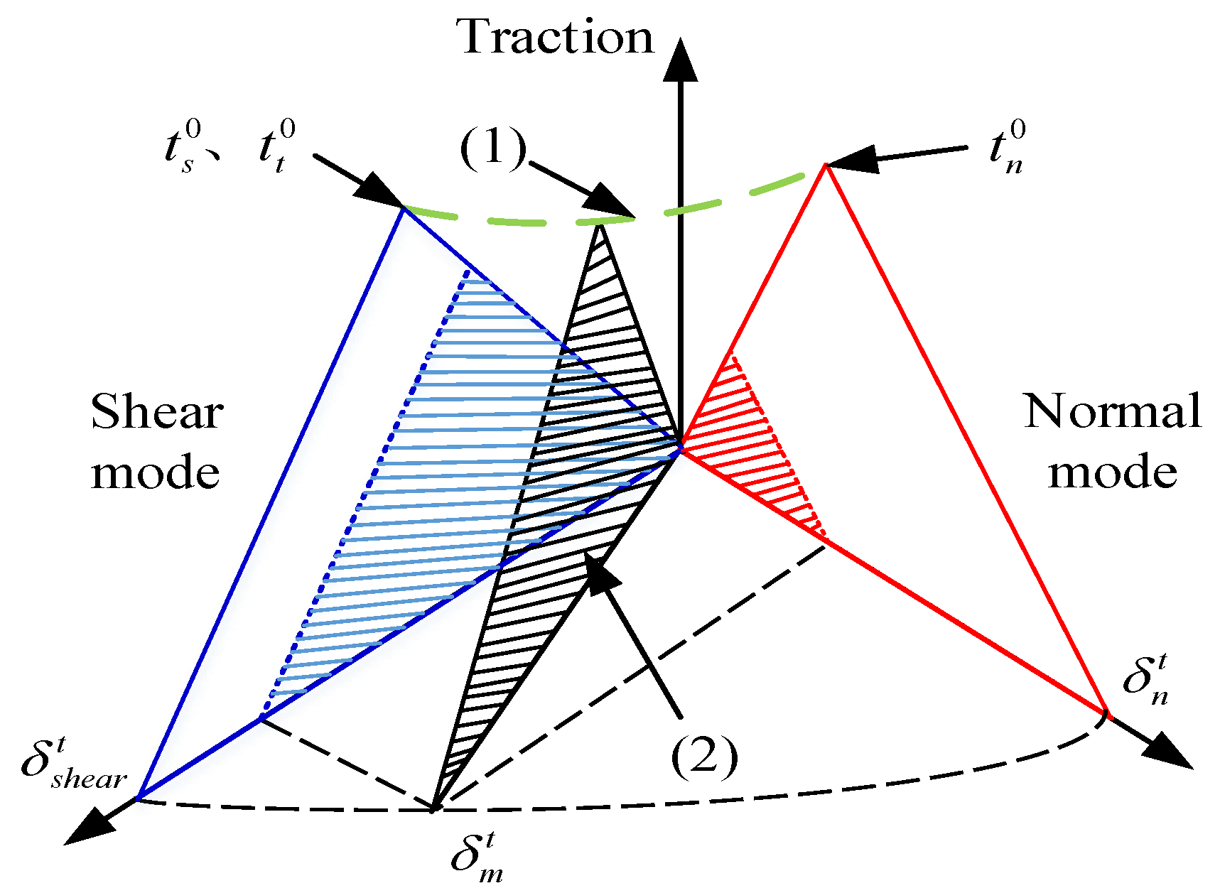
2.1. Materials and Constitutive Model

SFRC composites are inhomogeneous at the mesoscale. The establishment of RVE corresponds to the stress–strain distribution of homogeneous materials, so that the calculation of macroscopic SFRC composites is decoupled from the microscopic ones. Based on this, the mechanical response of RVE can reflect the mechanical properties of macroscopic SFRC composites. The Vsf is an important index that affects the performance of SFRC. Based on literature reports [26], two types of steel fibers, the straight type and end-hook type with a diameter of 0.7 mm and a length of 30 mm, were used in this paper. The interfacial strength was set as 1, 2, 3, 4 and 5 MPa and the concrete chosen was model C50. The performance parameters of steel fibers and concrete are shown in Table 1. Because of the tensile and compressive anisotropic hardening and damage of the concrete, the built-in CDP (Concrete Damaged Plastic) model in Abaqus was adopted for the concrete [31], and the plastic parameters of the plastic damage model of GB50010-2010 specification was used as reference [32], as shown in Table 2.
For the steel fiber/concrete interface, the CZM was used to simulate the interfacial bond-slip effect, as shown in Figure 1, showing the CZM damage evolution constitutive relationship. Here, t n 0 is the interface normal strength, t s 0 and t t 0 are the interface shear strengths, and the green dotted line represents the secondary stress criterion controlled by the above three parameters, that is, the initial damage criterion of the Cohesive element [27] can be given as:
t n t n 0 2 + t s t s 0 2 + t t t t 0 2 = 1
where t n is the normal stress of the interface; t s and t t are the two shear stresses of the interface, respectively; <> is the Macaulay bracket that is used to indicate that the pure compressive deformation (or stress) state will not cause damage; < t n > indicates that when the item is negative (i.e., compressive stress), its value is zero. In addition, the blue and red triangles in Figure 1 are the tensile–separation curves of shear and normal modes, respectively; the areas enclosed by the red and blue solid lines represent modes I (GIC) and II/III (GIIC/GIIIC) critical strain energy release rate, respectively; the areas shaded in red and blue represent the strain energy release rates in the normal and two tangential directions of the cohesive element, namely, GI and GII (or GIII); the shaded area in the black triangle represents the total critical strain energy release rate GC. Thus, the B-K criterion for judging the interface damage extension is:
G C = G I C + G I I C G I C G I I + G I I I G I + G I I + G I I I η
In Equation (2), η is the material parameter (usually taken as 1.35). When using Equations (1) and (2) to determine the initial damage and the crack growth, the performance parameters used for the cohesive element are presented in Table 3 [33].

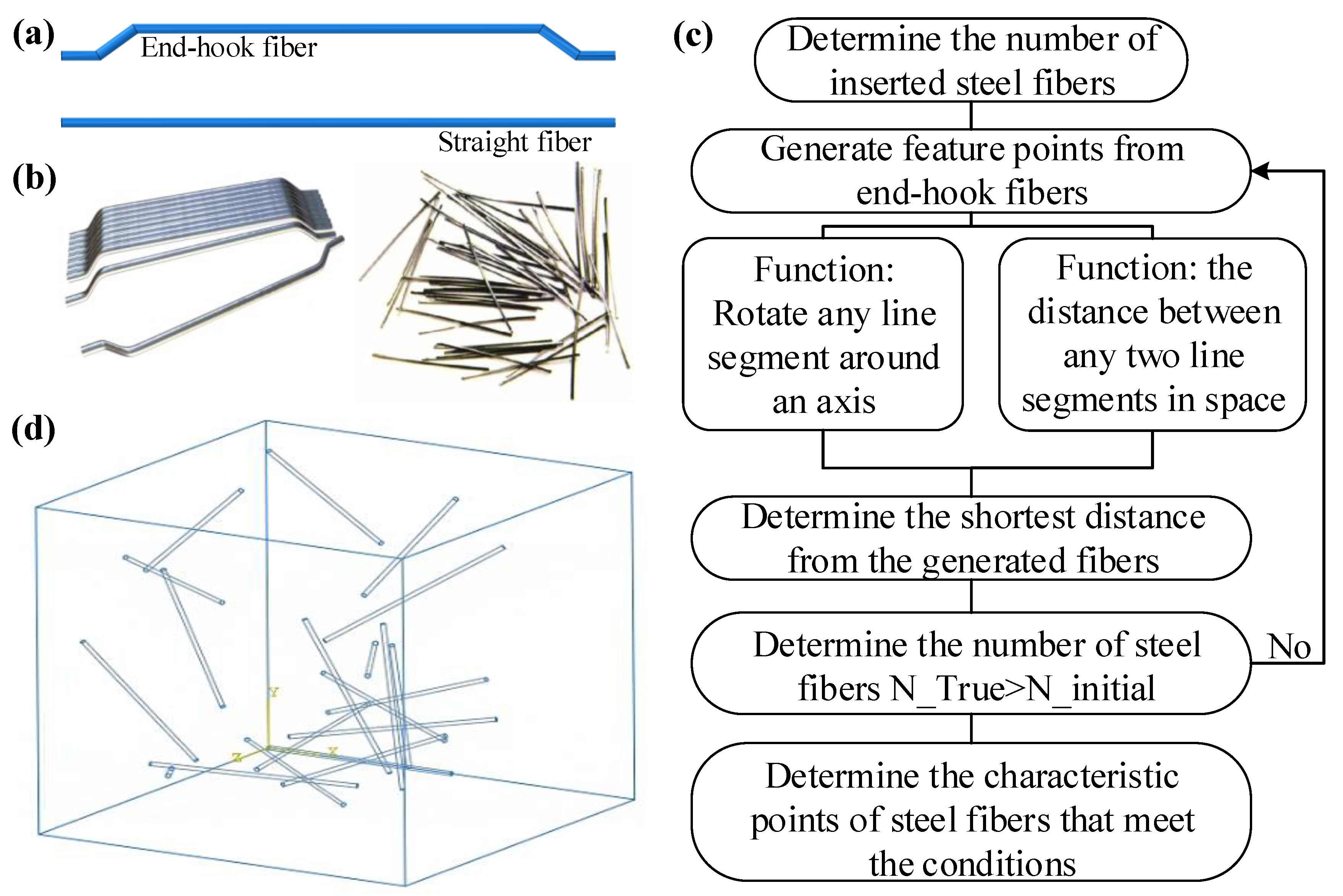
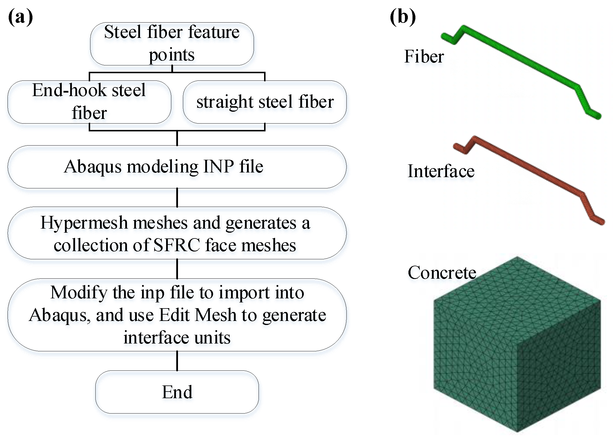
2.2. 3D RVE Tensile Model

Here, a secondary development of Python–Abaqus was used to establish the RVE model of the random steel fibers/concrete [33]. Figure 2a presents the models of end-hook and straight steel fibers in Abaqus, and the corresponding physical fibers are given in Figure 2b. Since this paper seeks to explore the effects of different shapes of steel fibers on the strength of the SFRC, the number and random positions of these two steel fibers should be the same. The Python algorithm was used to determine the node collection point whereat two fibers would not cross each other, as shown in Figure 2c. Firstly, the random position was controlled by a set of random coordinates and two corner values to construct the distance function between any two-line segments in space and the function of any line rotating around any point in space. Secondly, the end-hook fiber was divided into four segments from the broken line. We then calculated the shortest distance between the newly generated random end-hook fiber and the generated fibers. If all the distances were less than the steel fiber diameter, then the newly generated fiber was stored in the collection, otherwise another random fiber was regenerated. The two kinds of fibers generated by the algorithm have the same endpoints, which can ensure that the random position is exactly the same. By comparing the actual number of fibers with the predesigned fiber volume fraction, we judged whether to continue inserting new fibers, and repeat the process until the actual fibers reached the target value, at which point the generation process was completed. The final obtained RVE model is shown in Figure 2d.
The above method was used to generate two kinds of RVE with different shapes of steel fibers. Due to the relatively large aspect ratio of steel fibers in the RVE model, Abaqus has limitations when used in processing meshes, so Hypermesh was used to divide the model into tetrahedral meshes. We read the surface elements on the interface between steel fibers and concrete in batches to create a collection, and output the Abaqus inp file. By modifying the keyword, the grid set was transferred to the grid component, and so the edit mesh would generate the interface unit, as shown in Figure 3a.
Secondly, to qualitatively analyze the influence of steel fibers on the mechanical properties of the SFRC from the point of view of the bond-slip effect, the bilinear elastic–plastic model was adopted for the steel fibers, and the plastic damage model was used for the concrete. Therefore, in the 3D RVE model, C3D6 tetrahedral elements were used for both the concrete and the steel fibers, and the COH3D6 cohesive element was used to simulate the bond-slip effect between steel fibers and the concrete. The meshing was given in Figure 3b. In order to visualize the damage phenomenon of the concrete, the quasi-static display analysis step was used, and the reaction force and displacement of the reference point were selected from the field variable output.
Based on the above proposed RVE models and taking interfacial strength parameters and fiber shapes into consideration, ten RVE models were established. The first series of RVE contained straight steel fibers (SFs) with interfacial strengths of 1, 2, 3, 4, and 5 MPa, respectively. The second series of RVE contained end-hook fibers (EFs) with interfacial strengths of 1, 2, 3, 4 and 5 MPa, respectively. Table 4 presents these ten groups of RVE models, from which the influence of steel fiber types and interfacial strengths on the tensile properties of SFRC could be obtained.

3. Results and Discussion

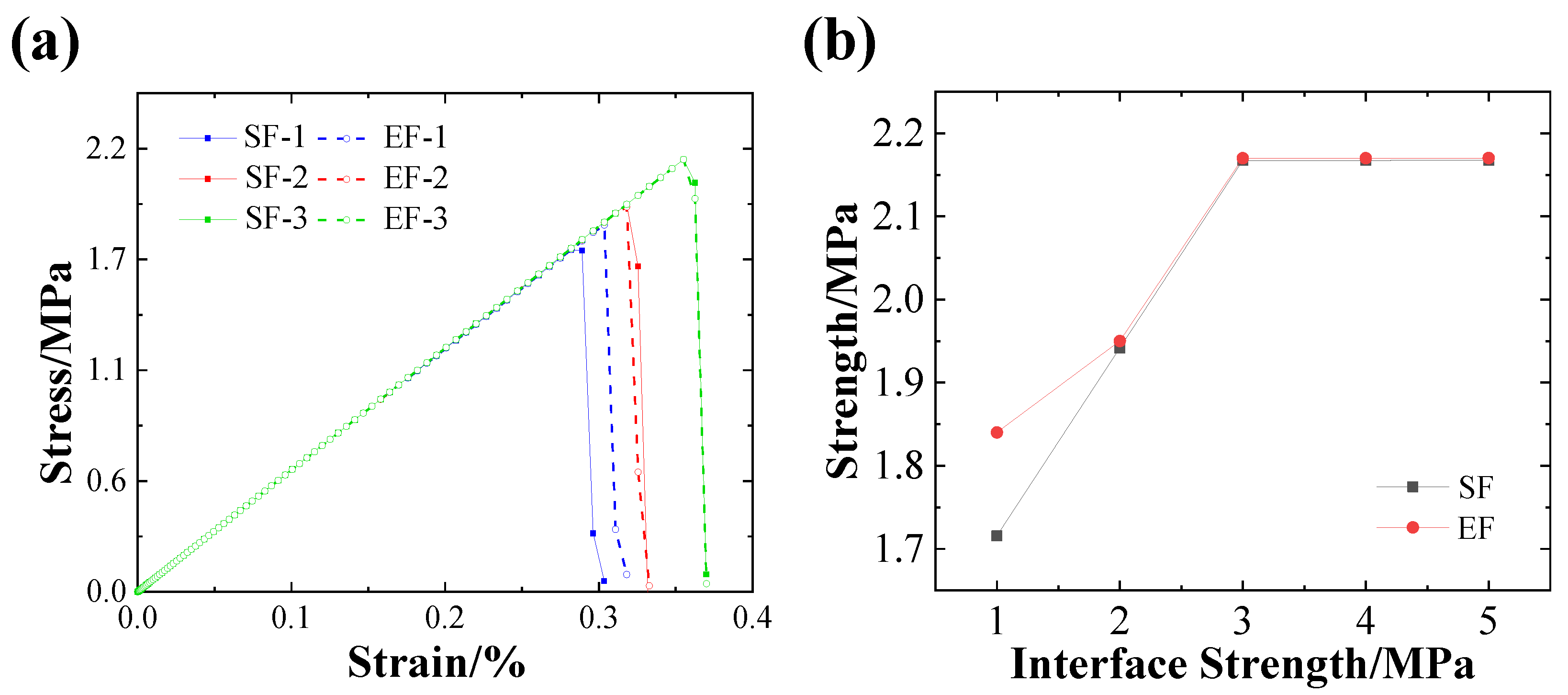
3.1. Effect on the Tensile Strength

According to the pre-analysis results, the fracture toughness shown in Table 3 has little influence on the ultimate strength of the SFRC. Therefore, the fracture toughness remains unchanged in the calculation. Additionally, when the interfacial strength is greater than 3 MPa, the yielded stress–strain curves almost overlap each other. Therefore, Figure 4a shows the tensile stress–strain curves of SFRC with interfacial strengths of 1–3 MPa. It can be seen that the steel fiber shapes and interfacial strengths have little effect on the stiffness of the SFRC. The obtained tensile strength is given in Figure 4b. It can be seen from Figure 4b that when the interfacial strength is lower than 2 MPa, the reinforcing effect of EFs is better than that of SFs. Additionally, if the interfacial strength is 1 MPa, the tensile strength of the SFRC with end-hook steel fibers is increased by 7% when compared to the SFRC with straight steel fibers. Additionally, when the interfacial strength approaches or exceeds 2.64 MPa (strength of concrete), these two steel fibers show similar reinforcing effects on the SFRC. Moreover, when the interfacial strength reaches 3 MPa (about 14% higher than the strength of concrete), these two steel fibers no longer show a reinforcing ability in relation to the strength of the SFRC. Therefore, Figure 4 proves that when the interfacial strength between steel fibers and concrete is relatively weak (less than 2 MPa), using the end-hook fibers as reinforcing is a better choice, while if the interfacial strength is high enough (close to or greater than the strength of concrete), choosing the straight fibers for reinforcing is relatively simple and effective.

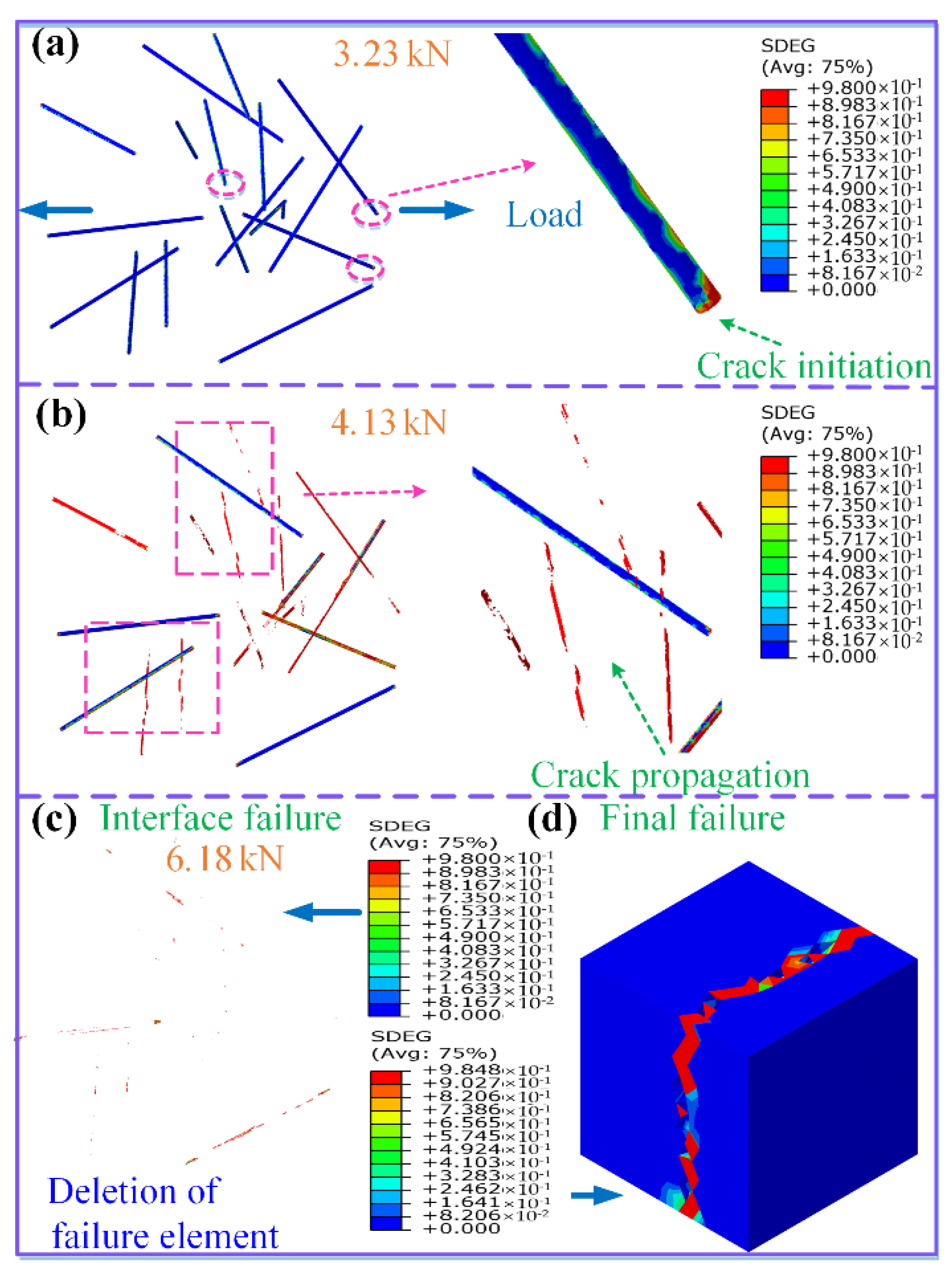
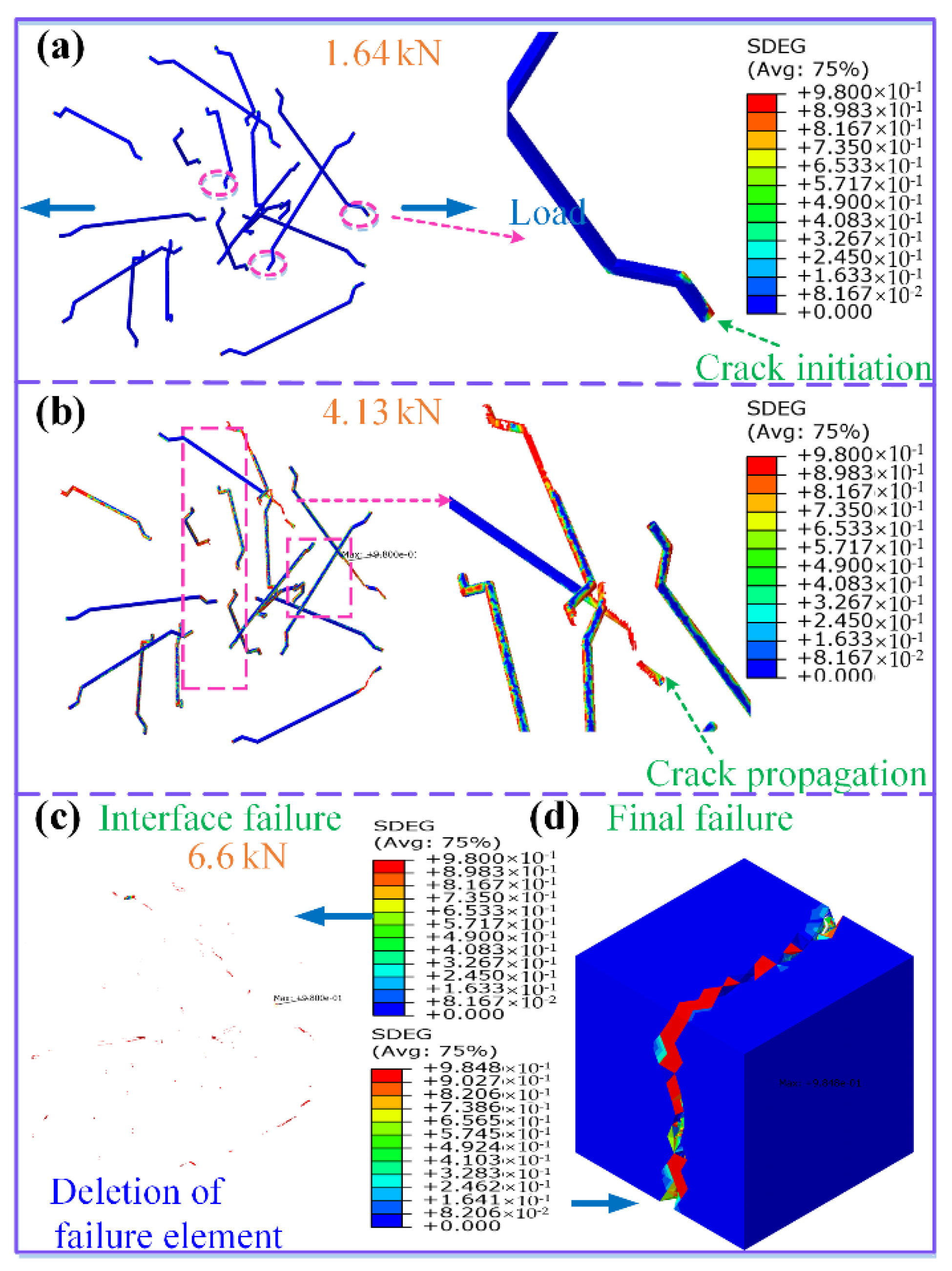
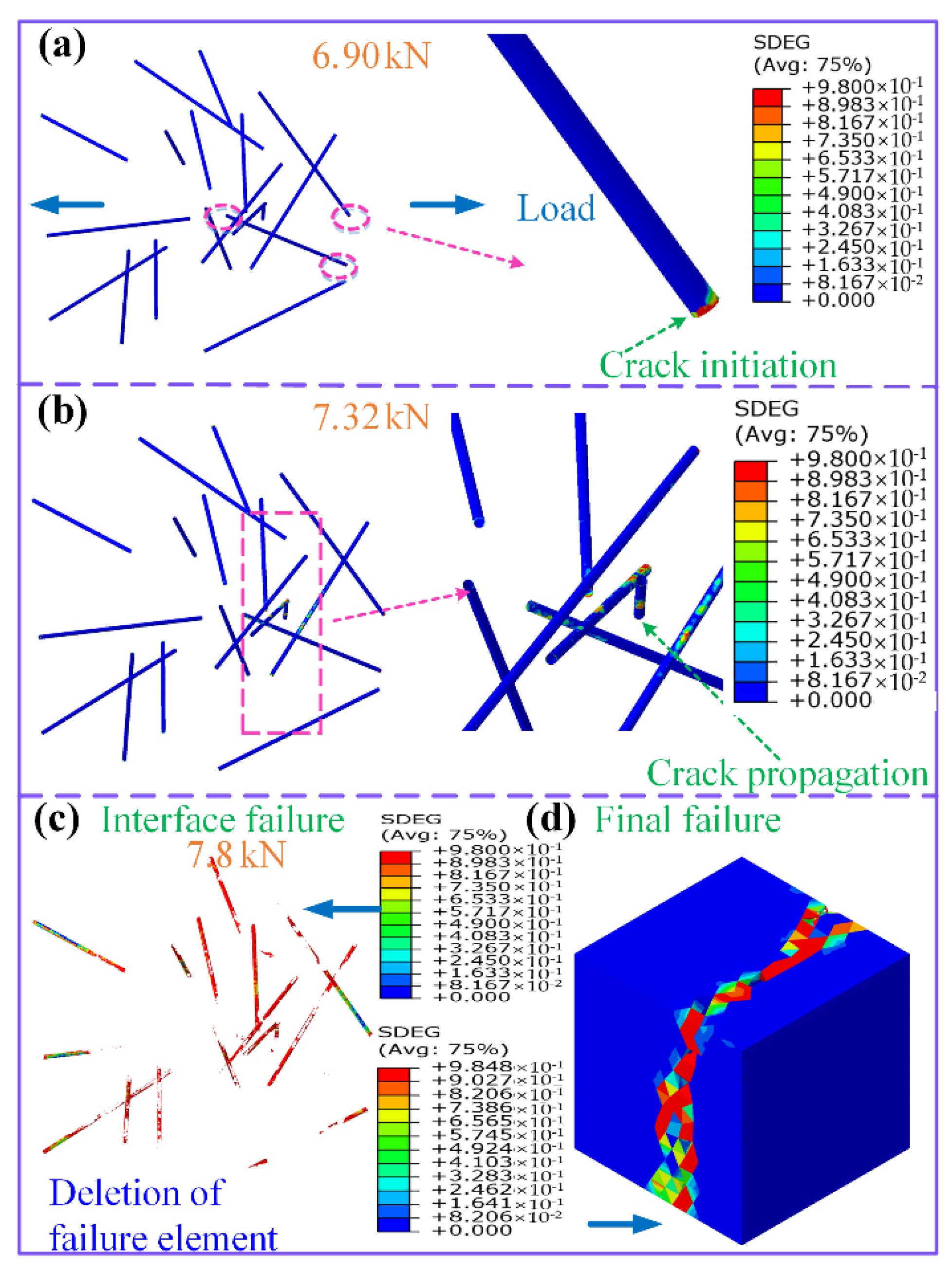
3.2. Effects on the Interfacial Damage and Failure Modes

3.2.1. With Low Interfacial Strength

Figure 5 gives the mesoscale failure process of the SFRC with SFs at a low interfacial strength of 1 MPa. Figure 5a indicates the initial failure of fibers/concrete interfaces in the RVE, which shows that when the external load reaches 3.23 kN, cracks begin to initiate at the end interface because of stress concentration, and cracks propagate along the interface due to the fact that the interfacial strength is lower than the strength of concrete. Figure 5b suggests that when the external load achieves 4.13 kN, crack propagation occurs at the interface perpendicular to the loading direction. This is because the interface perpendicular to the loading direction bears a large normal load, while the interface parallel to the loading direction mainly bears shear load; therefore, the damage mode is dominated by a mode-I crack. As shown in Figure 5c,d, when the crack propagates from the end interface to the concrete matrix, the crack extends quickly with the increase in load. When the crack reaches the SFRC surface, a penetrating crack is formed, thus the SFRC fails macroscopically, and the ultimate load is 6.18 kN.
Figure 6 shows the mesoscale failure process of SFRC with EFs at a low interfacial strength of 1 MPa. Figure 6a gives the initial interface damage of the SFRC RVE, which indicates that when the external load reaches 1.64 kN, cracks begin to occur at the end interfaces and at the fiber corners due to stress concentration. It can be seen from Figure 6b that when the external load reaches 4.13 kN, cracks begin to propagate along the interface, which propagate more significantly at these interfaces nearly perpendicular to the loading direction. This is because these interfaces bear large normal loads, and cracks are easy to occur. Moreover, Figure 6c,d suggest that the SFRC with EFs is still dominated by interface damage, where cracks initiate at the fiber ends, propagate into the concrete matrix, and finally fail macroscopically. The obtained ultimate load is 6.60 kN.
It can be seen from Figure 5 and Figure 6 that the failure modes of the SFRC with SFs or EFs are similar at low interfacial strengths. However, due to the additional corners of the EFs, the external load induced by the initial interface damage of the SFRC with EFs is lower than that of the SFRC with SFs. Alternatively, it can be seen from Figure 5 and Figure 6 that the SFs-modified SFRC has more damaged areas than the EFs-modified SFRC (SDEG > 0.98, shown in red), which means the initial crack onset rate at the interface of the SFRC with EFs is lower than that of the SFs-modified SFRC. Additionally, the external load corresponding to interfacial crack propagation for these two SFRCs is the same, obtained as 4.13 kN, where the propagation rate of interfacial cracks of the EFs-modified SFRC is obviously slower than that of the SFs-modified SFRC. More importantly, the tensile strength of the EFs-modified SFRC is 7% higher than that of the SFs-modified SFRC when the interfacial strength is 1 MPa.

3.2.2. With High Interfacial Strength

Figure 7 gives the mesoscale damage process of the SFs-modified SFRC at the relatively high interfacial strength of 5 MPa. As shown in Figure 7a, when the external load reaches 6.9 kN, a small number of initial cracks occur at the end interfaces. With the external load increasing to 7.32 kN (Figure 7b), the cracks propagate a short distance along the interfaces and immediately extend into the concrete matrix because the interfacial strength is higher than that of the concrete matrix. Figure 7c,d present the damage diagrams of the interfaces and the concrete matrix at the final failure moment, respectively. It can be seen that with high interfacial strength, the damage percentage of interfaces at the final failure moment is much smaller than that of the concrete matrix, and the concrete damage is the dominating failure mode of the SFRC. The obtained ultimate load is 7.80 kN. Once again, Figure 8 presents the mesoscale damage process of EFs-modified SFRC at the high interfacial strength of 5 MPa. When the external load reaches 4.5 kN (Figure 8a), tiny initial cracks appear at the end interfaces. As the external load continues to increase to 7.32 kN (Figure 8b), the cracks extend from both ends of the fibers to their middle parts, and then quickly extend into the concrete matrix. Figure 8c,d give the damage diagrams of the interfaces and the concrete matrix at the final failure moment, respectively. Here, the cracks have propagated to the surface of the SFRC, accompanied by a large damage area in the concrete (Figure 8d), which eventually leads to macroscopic damage to the SFRC, with an ultimate load of 7.81 kN.
It can be seen from Figure 7 and Figure 8 that due to the additional corners of the EFs, cracks easily initiate in the EFs-modified SFRC. Under high interfacial strength, both interfacial strengths and fiber shapes reach their reinforcing threshold, and the failure mode is dominated by the concrete matrix. That is, when the interfacial strength is 5 MPa, the EFs-modified SFRC and the SFs-modified SFRC show the same damage modes and ultimate strengths.
It can be concluded from Figure 4, Figure 5, Figure 6, Figure 7 and Figure 8 that the external load corresponding to the initial damage is relatively high in the case of high interfacial strength (Figure 7 and Figure 8), and otherwise is reverse (Figure 5 and Figure 6). The tensile strength of the SFRC increases with the increase in the interfacial strength. The addition of low-fiber volume content steel fibers into concrete does not show a reinforcing effect, and the induced interface is very easy to crack.

4. Conclusions

This paper uses Abaqus–Python–Hypermesh to establish a 3D RVE for the SFRC with different types of steel fibers and different interfacial strengths. The results show that when the interfacial strength is less than 2 MPa, end-hook steel fibers have a better reinforcing effect than straight steel fibers, with a maximum enhancement of about 7% in the concrete compared to the straight steel fibers. Additionally, when the interfacial strength approaches the concrete’s strength, both fibers show similar reinforcing effects. Moreover, interfacial damage is the dominating failure mode in cases of low interfacial strength, and the main failure mode is the concrete if the interfacial strength is high. Furthermore, the induced initial damage load in the end-hook steel fibers-modified SFRC is lower than that in the straight steel fibers-modified SFRC, because more ends and corners present in the former would cause more stress concentration points. However, the crack propagation rate in the end-hook steel fibers-modified SFRC is slower than that in the straight steel fibers-modified SFRC. Summarily, interfacial strength and fiber type are the main parameters that determine the effect of the addition of fibers into concrete. This research provides a better design guideline for the modification of concrete. Real interface strength testing, SFRC tensile experimental verification, and more finite element groups of high-fiber volume content will be considered in future research.

Author Contributions

Conceptualization, H.W.; methodology, H.W.; software, H.W. and Y.J.; formal analysis, H.W.; data curation, Y.J.; writing—original draft, Y.J.; writing—review and editing, L.L. All authors have read and agreed to the published version of the manuscript.

Funding

This research received no external funding.

Institutional Review Board Statement

Not applicable.

Informed Consent Statement

Not applicable.

Data Availability Statement

The data for the study are not available publicly.

Acknowledgments

This research was financially supported by the Nantong Railway Construction Component Co., Ltd. The simulation analysis support from engineer Changtao Wang and Zhanji Wang is appreciated.

Conflicts of Interest

The authors declare no conflict of interest.

References

  1. Abdallah, S.; Fan, M.; Rees, D.W.A. Bonding mechanisms and strength of steel fiber–reinforced cementitious composites: Overview. J. Mater. Civ. Eng. 2018, 30, 04018001. [Google Scholar] [CrossRef]
  2. Marcos-Meson, V.; Michel, A.; Solgaard, A.; Fischer, G.; Edvardsen, C.; Skovhus, T.L. Corrosion resistance of steel fibre reinforced concrete-A literature review. Cem. Concr. Res. 2018, 103, 1–20. [Google Scholar] [CrossRef] [Green Version]
  3. Shah, A.A.; Ribakov, Y. Recent trends in steel fibered high-strength concrete. Mater. Des. 2011, 32, 4122–4151. [Google Scholar] [CrossRef]
  4. Divyah, N.; Prakash, R.; Srividhya, S.; Sivakumar, A. Parametric study on lightweight concrete-encased short columns under axial compression-Comparison of design codes. Struct. Eng. Mech. 2022, 83, 387–400. [Google Scholar]
  5. Divyah, N.; Thenmozhi, R.; Neelamegam, M.; Prakash, R. Characterization and behavior of basalt fiber-reinforced lightweight concrete. Struct. Concr. 2021, 22, 422–430. [Google Scholar] [CrossRef]
  6. Prakash, R.; Thenmozhi, R.; Raman, S.N.; Subramanian, C.; Divyah, N. Mechanical characterisation of sustainable fibre-reinforced lightweight concrete incorporating waste coconut shell as coarse aggregate and sisal fibre. Int. J. Environ. Sci. Technol. 2021, 18, 1579–1590. [Google Scholar] [CrossRef]
  7. Prakash, R.; Divyah, N.; Srividhya, S.; Avudaiappan, S.; Amran, M.; Naidu Raman, S.; Guindos, P.; Vatin, N.I.; Fediuk, R. Effect of Steel Fiber on the Strength and Flexural Characteristics of Coconut Shell Concrete Partially Blended with Fly Ash. Materials 2022, 15, 4272. [Google Scholar] [CrossRef]
  8. Prakash, R.; Thenmozhi, R.; Raman, S.N.; Subramanian, C. Characterization of eco-friendly steel fiber-reinforced concrete containing waste coconut shell as coarse aggregates and fly ash as partial cement replacement. Struct. Concr. 2020, 21, 437–447. [Google Scholar] [CrossRef]
  9. Liang, X.; Wu, C. Meso-scale modelling of steel fibre reinforced concrete with high strength. Constr. Build. Mater. 2018, 165, 187–198. [Google Scholar] [CrossRef]
  10. Wang, W.T.; Wei, Y.Y.; Han, J.; Hong, J.; Zeng, Y. Mechanical Properties of Ultrahigh Performance Steel Fiber Reinforced Concrete: Experimental Study. Appl. Math. Mech. 2014, 4, 295–298. [Google Scholar]
  11. Nihat, K.; Bahadur, A. Glass Fiber–Reinforced Sprayed Concrete: Physical, Mechanical, and Durability Properties. J. Mater. Civ. Eng. 2021, 33, 04020396. [Google Scholar]
  12. Zhang, R.; Jin, L.; Du, X. Three-dimensional meso-scale modelling of failure of steel fiber reinforced concrete at room and elevated temperatures. Constr. Build. Mater. 2021, 278, 122368. [Google Scholar] [CrossRef]
  13. Banthia, N.; Nandakumar, N. Crack growth resistance of hybrid fiber reinforced cement composites. Cem. Concr. Compos. 2003, 25, 3–9. [Google Scholar] [CrossRef]
  14. Liu, R.; Li, H.; Jiang, Q.; Meng, X. Experimental investigation on flexural properties of directional steel fiber reinforced rubberized concrete. In Structures; Elsevier: Amsterdam, The Netherlands, 2020; Volume 27, pp. 1660–1669. [Google Scholar]
  15. Ramírez, J.A.L.; Juan, L.M.; Carrillo, J. Material Damage Evolution for Plain and Steel-Fiber-Reinforced Concrete under Unconfined Compression Loading by Dynamic Ultrasonic Tests. Arab. J. Sci. Eng. 2018, 43, 5667–5675. [Google Scholar] [CrossRef]
  16. Wang, C. Experimental investigation on behavior of steel fiber reinforced concrete (SFRC). UC Res. Repos. 2006. [Google Scholar] [CrossRef]
  17. Xu, M.; Wille, K. Calibration of K & C concrete model for UHPC in LS-DYNA. Adv. Mater. Res. 2015, 141, 04015051. [Google Scholar]
  18. Wu, Z.; Shi, C.; He, W.; Wu, L. Effects of steel fiber content and shape on mechanical properties of ultra high performance concrete. Constr. Build. Mater. 2016, 103, 8–14. [Google Scholar] [CrossRef]
  19. Ferrotto, M.F.; Fischer, O.; Cavaleri, L. A strategy for the finite element modeling of FRP-confined concrete columns subjected to preload. Eng. Struct. 2018, 173, 1054–1067. [Google Scholar] [CrossRef]
  20. Youssf, O.; ElGawady, M.A.; Mills, J.E.; Ma, X. Finite element modelling and dilation of FRP-confined concrete columns. Eng. Struct. 2014, 79, 70–85. [Google Scholar] [CrossRef]
  21. Pan, J.; Zhong, W.; Wang, J.; Zhang, C. Size effect on dynamic splitting tensile strength of concrete: Mesoscale modeling. Cem. Concr. Compos. 2022, 128, 104435. [Google Scholar] [CrossRef]
  22. Xu, S.C.; Wu, C.Q.; Liu, Z.Z.; Su, Y. Effects of the Nano Materials and Steel Fibre on Early-Age Properties of Ultra-High Performance Concrete. Bull. Chin. Ceram. Soc. 2014, 33, 542–546. [Google Scholar]
  23. Zhao, Q.S.; Xu, S.C.; Liu, Z.C. Microscopic numerical simulation of the uniaxial compression of steel fiber reinforced ultra-high performance concrete. Acta Mater. Compos. Sin. 2018, 35, 13. [Google Scholar]
  24. Wu, P.T.; Wu, C.Q.; Liu, Z.X.; Xu, S.C. Numerical simulation of SHPB test of ultra-high performance fiber reinforced concrete with meso-scale mode. Sci. China Phys. Mech. Astron. 2020, 50, 13. [Google Scholar]
  25. Tian, H.W.; Zhou, Z.; Lu, J.P.; Peng, Z. Meso-scale numerical simulation of axial compression performance of fiber reinforced polymer composite-confined ultra-high performance concrete. Acta Mater. Compos. Sin. 2020, 37, 10. [Google Scholar]
  26. Kim, S.M.; Al-Rub, R.K.A. Meso-scale computational modeling of the plastic-damage response of cementitious composites. Cem. Concr. Res. 2011, 41, 339–358. [Google Scholar] [CrossRef]
  27. Zhou, R.; Lu, Y. A mesoscale interface approach to modelling fractures in concrete for material investigation. Constr. Build. Mater. 2018, 165, 608–620. [Google Scholar] [CrossRef] [Green Version]
  28. Trawinski, W.; Tejchman, J.; Bobinski, J. A three-dimensional meso-scale modelling of concrete fracture based on cohesive elements and X-ray CT images. Eng. Fract. Mech. 2018, 189, 27–50. [Google Scholar] [CrossRef]
  29. Abbas, S.; Soliman, A.M.; Nehdi, M.L. Exploring mechanical and durability properties of ultra-high performance concrete incorporating various steel fiber lengths and dosages. Constr. Build. Mater. 2015, 75, 429–441. [Google Scholar] [CrossRef]
  30. Zhou, R.; Chen, H.M.; Lu, Y. Mesoscale modelling of concrete under high strain rate tension with a rate-dependent cohesive interface approach. Int. J. Impact Eng. 2020, 139, 103500. [Google Scholar] [CrossRef]
  31. Abaqus Inc. Abaqus Analysis User’s Manual v.2016; Dassault Systemes: Paris, France, 2016. [Google Scholar]
  32. China Association for Engineering Construction Standardization. CECS13:19, Test Methods for Steel Fiber Reinforced Concrete; China Association for Engineering Construction Standardization: Beijing, China, 1989. [Google Scholar]
  33. Thilakarathna, P.S.M.; Baduge, K.K.; Mendis, P.; Vimonsatit, V.; Lee, H. Mesoscale modelling of concrete–a review of geometry generation, placing algorithms, constitutive relations and applications. Eng. Fract. Mech. 2020, 231, 106974. [Google Scholar] [CrossRef]
Figure 1. Constitutive model of cohesive element.
Sustainability 14 15803 g001
Figure 2. (a) 3D models of end-hook and straight steel fiber, (b) real end-hook and straight steel fibers, (c) generation process of RVE model, (d) 3D RVE geometric model.
Sustainability 14 15803 g002
Figure 3. (a) Mesh part generation process, (b) meshes of steel fiber, interface and concrete.
Sustainability 14 15803 g003
Figure 4. Tensile simulation results of SFRC with various shapes of fibers and different interfacial strengths, (a) stress–strain curves, (b) tensile strength.
Sustainability 14 15803 g004
Figure 5. Mesoscale failure process of SFRC with SFs at low interfacial strength 1 MPa, (a) initial interface damage, (b) propagation of interface crack, (c) interface failure, (d) SFRC failure.
Sustainability 14 15803 g005
Figure 6. Mesoscale failure process of SFRC with EFs at low interfacial strength 1 MPa, (a) initial interface damage, (b) propagation of interface crack, (c) interface failure, (d) SFRC failure.
Sustainability 14 15803 g006
Figure 7. Mesoscale failure process of SFRC with SFs at high interfacial strength of 5 MPa, (a) initial interface damage, (b) propagation of interface crack, (c) interface failure, (d) SFRC failure.
Sustainability 14 15803 g007
Figure 8. Mesoscale failure process of SFRC with EFs at high interfacial strength of 5 MPa, (a) initial interface damage, (b) propagation of interface crack, (c) interface failure, (d) SFRC failure.
Sustainability 14 15803 g008
Table 1. Material parameters.
MaterialDensity/t/mm3Modulus/GPaPoisson’s
Ratio
Steel fiber7.8 × 10−92000.25
Concrete2.5 × 10−936.60.2
Table 2. Plastic parameters of CDP damage.
Dilation Angle/°EccentricityStress RatioViscosity Parameter
30.50.10.6660.001
Yield stress
/MPa
Inelastic strainYield stress
/MPa
Cracking strain
12.9602.640
16.515.23 × 10−52.545.13 × 10−5
20.731.05 × 10−42.366.72 × 10−5
24.301.75× 10−42.178.34 × 10−5
27.232.63× 10−41.999.93 × 10−5
Table 3. Interface parameters of steel fiber/concrete.
Modulus/MPa t n 0 /MPa t s 0 / t t 0 /MPa GIC/N/mm1GIIC = GIIIC/N/mm1
1 × 1071–51–50.0250.625
Table 4. SFRC simulation groups.
GroupInterface Strength/MPaSteel Fiber Type
SFs (1–5)1\2\3\4\5Straight fibers
EFs (1–5)1\2\3\4\5End-hook fibers
Publisher’s Note: MDPI stays neutral with regard to jurisdictional claims in published maps and institutional affiliations.

