Article

Joint Estimation Method with Multi-Innovation Unscented Kalman Filter Based on Fractional-Order Model for State of Charge and State of Health Estimation

1
Key Laboratory of Enhanced Heat Transfer and Energy Conservation of MOE, Beijing Key Laboratory of Heat Transfer and Energy Conversion, Faculty of Environment and Life, Beijing University of Technology, Beijing 100124, China
2
China Automotive Technology and Research Center Co., Ltd., Tianjin 300300, China
3
School of Information Science and Technology, Southwest Jiaotong University, Chengdu 611756, China
*
Author to whom correspondence should be addressed.
Sustainability 2022, 14(23), 15538; https://doi.org/10.3390/su142315538
Submission received: 22 October 2022 / Revised: 18 November 2022 / Accepted: 19 November 2022 / Published: 22 November 2022
(This article belongs to the Special Issue Toward Carbon Neutrality: Renewable Energy and Energy Engineering)

Abstract

:
This study simulates the polarization effect during the process of battery charging and discharging, and investigates the characteristics of the process. A fractional-order model (FOM) is established and the parameters of the FOM are identified with the adaptive genetic algorithm. As Kalman filter estimation causes error accumulation over time, using the fractional-order multi-innovation unscented Kalman filter (FOMIUKF) is a better choice for state of charge (SOC) estimation. A comparative study shows that the FOMIUKF has higher accuracy. A multiple timescales-based joint estimation algorithm of SOC and state of health is established to improve SOC estimation precision and reduce the amount of computation. The FOMIUKF algorithm is used for SOC estimation, while the UKF algorithm is used for SOH estimation. The joint estimation algorithm is then compared and analyzed alongside other Kalman filter algorithms under different dynamic operating conditions. Experimental results show that the joint estimation algorithm possesses high estimation accuracy with a mean absolute error of under 1% and a root mean square error of 1.35%.

1. Introduction

Mitigating climate warming by developing renewable and sustainable energy and environmental protection are considered key problems of future development [1,2]. Increasing the proportion of renewable energy, balancing fluctuations in the supply and demand of electrical energy, improving energy conversion efficiency, and developing new energy technologies are the directions of the future energy revolution [3,4,5]. Popularizing electric vehicles has proved to be one of the effective means to solve the environmental problems caused by the automobile industry, such as pollution and the energy crisis. Precise estimation of the vehicle battery SOC (state of charge) and SOH (state of health) is vital to improve energy utilization, extend battery life, and ensure safe driving [6]. Therefore, researchers have conducted numerous studies to develop a safe and reliable SOC estimation method. Many methods mentioned in previous studies, for instance, open circuit voltage, Coulomb counting, model-based methods, and machine learning, have already been widely used for battery SOC estimation [7].
Accurate battery models are essential to study the effect of a battery’s internal parameters on its performance. Currently, commonly used battery models are the electrical ECM (equivalent circuit model), the electrochemical impedance model, the empirical model, and the data-driven model [8]. In addition, fractional-order calculus has been applied to overcome the drawbacks of the IOM (integer-order model) of batteries [9]. Wang et al. proposed a fractional-order model (FOM) of a hybrid power source system and used particle swarm optimization for parameter identification. The experimental results showed a high accuracy of FOM, with an average absolute error of less than 20 mV, and a mean relative error of less than 0.5% [9]. Ruan et al. introduced a multi-timescale FOM and validated it with experimental data. From the results, it could also be seen that the model possesses good adaptability and high accuracy, with a maximum relative error of less than 0.86% [10]. Zhang et al. established an ECM system based on a fractional variable-order model and used experimental data for model verification. The results indicated that the MAE (mean absolute error) and RMSE (root mean square error) of the proposed model are lower than those with the IOM and the fractional constant-order model [11]. Eddine et al. presented a fractional model for impedance physical parameters estimation [12]. Sánchez et al. constructed a model with fractional-order dynamics for the health assessment of lithium iron phosphate. The results showed that the health state estimation generated by fractional-order networks is always better than that of statistical and fuzzy models [13]. Zou et al. reviewed a FOM applied to electrochemical energy storage and investigated its computational efficiency and accuracy. It can be seen from the result that, compared to an IOM, the accuracy of the FOM was 15–30% higher [14]. Hidalgo-Reyes et al. proposed an EKF (extended Kalman filter) with Mittag–Leffler memory based on FOM for SOC estimation. The results indicated the high precision and robustness of the proposed algorithm for SOC estimation [15].
The observability of the battery model is necessary for parameter identification and state estimation. Meng et al. [16] conducted an observability analysis of an extended ECM and validated the effectiveness of the results by numerical simulation. Fotouhi et al. [17] proposed a framework to estimate SOC using the identified parameters and assessed the framework by performing an observability analysis. The results showed that the mean error of the SOC was approximately 4%. Rausch et al. [18] investigated the nonlinear observability and identifiability of battery packs. Zhao et al. [19] conducted an observability analysis of an ECM and estimated the SOC of batteries in the presence of sensor biases. Experimental results showed that it is very important to consider the nonlinearity of the model in the estimation algorithm, which highlights the importance of observability analysis in state estimation. Fotouhi et al. [20] investigated parameter identification of ECM and carried out a SOC observability analysis to determine the influence of temperature on performance.
Data-driven SOC estimation methods are developed by analyzing a large amount of data. Ahmed et al. proposed an approach of scaling the EKF for SOC estimation and validated it with experimental data at different temperatures. The results showed a 90% reduction from 10% to 1% in the maximum error of SOC estimation by using the proposed scaling method [21]. Sun et al. presented an adaptive EKF for SOC estimation. The results showed that there is an enhancement in the accuracy of SOC estimation [22]. Wang et al. developed a model framework of a battery, with an unscented particle filter method for SOC estimation, and validated the framework using experimental data at different temperatures under different dynamic driving cycles. The results demonstrated that the proposed method has the properties of fast convergence speed and high accuracy [23]. Knap et al. used an unscented Kalman filter (UKF) with online parameter identification for SOC estimation. The results showed the high accuracy of the method with a SOC estimation RMSE of 0.53% [24]. Zhu et al. developed a co-estimation method for parameter identification and SOC estimation. The results indicated an MAE of less than 1.2% for SOC estimation [25]. Sun et al. constructed an ECM-based joint SOC estimation method and verified it with experimental data under dynamic driving cycles. The results confirmed that there is a significant improvement in the accuracy of SOC estimation with the utilization of the proposed approach [26]. Xue et al. built a state-space model and demonstrated an integrated algorithm to describe the degradation and assess the RUL (remaining useful life) of a lithium-ion battery. The results indicated that the proposed method can achieve precise prediction of RUL [27]. Křivík et al. introduced a SOC estimation method for lead-acid batteries through electrochemical impedance spectroscopy. The results verified that higher accuracy of SOC estimation can be achieved by combining the open circuit voltage, the measured phase angle, and the Z-modulus [28]. Ling et al. developed a SOC estimation method based on the probabilistic fusion of an adaptive high-degree cubature Kalman filter and an adaptive cubature Kalman filter to enhance SOC estimation accuracy. The results show that the accuracy can be improved through the proposed approach [29]. Girade et al. introduced an adaptive version of the equivalent consumption minimization strategy with a reference based on the SOC to keep the most efficient hybrid operation during the charge and discharge cycles. The results indicated that the average fuel economy was improved by 5% compared to the baseline strategy [30].
The development trend of battery SOC estimation technology is toward the use of a mixture of estimation methods, which requires a trade-off between accuracy and robustness, ease of implementation, low complexity, and small calculation overburden [31]. Loukil et al. presented a hybrid SOC method that combined an offline method and an online algorithm, and the results demonstrated the validity of this hybrid approach [31]. Ragone et al. presented a multiphysics model to generate data for SOC estimation with different machine-learning methods [32]. Ee et al. proposed a SOC estimation approach using a deep neural network with a nonelectrical model. The results showed that the SOC estimation model on the basis of nonelectrical parameters has better estimation performance [33]. Sandoval-Chileño et al. constructed a SOC estimation method using extended state observers and validated it with data obtained by experiments. The results showed that the proposed approach has high robustness and performance [34]. Ceraolo et al. used the Luenberger state estimator for the estimation of SOC and conducted a sensitivity analysis of the effect of measurement error on SOC estimation [35]. Li et al. proposed a novel estimating algorithm for SOC and SOH and validated it through experimental data [36].
Multi-innovation (MI) is a method to predict the error information collected from an iterative algorithm to enhance the accuracy of posterior correction. Compared with a single innovation, MI can improve error correction. Although the amount of calculation increases slightly with MI, the calculation results are acceptable considering the improvement in estimating accuracy [37]. Li et al. introduced statistical information on the innovation sequence for model uncertainty identification, and, at the same time, proposed a combination algorithm to estimate SOC. The results indicated a good estimation performance of the proposed algorithm, which possesses better precision, robustness, and convergence [37]. Liu et al. developed an MI Kalman filter methodology for SOC estimation. From the experimental results, significantly enhanced accuracy and anti-interference ability of SOC estimation are achieved through the approach [38]. Ding et al. presented an MI gradient algorithm that can improve the convergence rate and the effectiveness was verified through simulation [39]. Sassi et al. presented an MI theory-based UKF for SOC estimation accuracy enhancement. The results indicated that the MIUKF (multi-innovation unscented Kalman filter) is robust under different operating scenarios [40]. Cui et al. built a state-space model of a battery and presented a MIUKF for SOC estimation. Experimental results indicated the validity of the proposed estimating algorithm through different dynamic tests [41].
The SOC and SOH algorithms are interdependent because they are coupled. The design of a collaborative SOC–SOH estimation algorithm is the basis for obtaining accurate SOC estimation under complex and variable real-world vehicle conditions. Liu et al. proposed a joint SOC and SOH estimation method based on a pseudo-2D model. The maximum SOH estimation error shown from the results was approximately 2.8%, and the SOC estimation error was lower than 2% [42]. Song et al. presented a joint estimating method with a least-squares support vector machine, along with a model-based unscented particle filter for SOH and SOC. The results indicated that the maximum estimating error of SOC and the RMSE of SOH estimation are reduced to less than 2% and 4%, respectively [43]. Xiong et al. developed a multistage model fusion algorithm that realized a joint estimation of SOC and capacity and verified it with a hardware-in-the-loop platform at different temperatures. The results indicated that high accuracy of SOC and capacity estimation can be achieved; furthermore, the relative errors in the SOC and capacity are less than 2% and 3.3%, respectively [44]. Zhang et al. introduced a joint estimating approach to assess the battery state of energy. The proposed approach was verified by experimental results using Federal Urban Driving Schedule tests. the results showed that the joint estimating method possessed good robustness and high accuracy [45]. Li et al. proposed a multistate joint estimation of a lithium-ion hybrid capacitor under a wide range of temperatures. The proposed method was validated under different dynamic driving cycles. It can be found from the result that the RMSE of the SOC, state of energy, and remaining useful energy estimation are 2.1%, 2.3%, and 0.9 W·h, respectively [46]. Li et al. presented a prognostic framework with a variant long short-term memory neural network to estimate the SOH and RUL. The results showed that the average root mean square error and conjunct error in the SOH and RUL were 0.0216 and 0.0831, respectively [47]. Cui et al. developed a coupling-loop nonlinear autoregressive algorithm, and an exogenous input neural network estimation model was utilized to estimate the SOH. The results indicated that the reductions in the absolute error, relative error, and the mean square error in SOH estimation were more than 50%, 50%, and 80%, respectively [48]. Yang et al. presented a novel fractional impedance model and a backpropagation neural network for the estimation of a lithium-ion battery SOH. The calculated error margin of SOH from the results was [−1.5%, 1.5%] [49]. Propp et al. utilized a dual extended Kalman filter for SOC estimation optimization. The results showed that the proposed approach had high precision and good convergence [50]. Meng et al. [51] proposed a cascaded framework for parameter and state estimation and validated the effectiveness of the proposed framework by numerical simulations. Park et al. [52] proposed an integrated model using a dual extended Kalman filter to estimate SOC and SOH. The results indicated that the mean absolute percentage errors of SOH/SOC were 0.5183% and 1.45%, respectively. Lai et al. [53] proposed a joint SOC/SOH estimation method considering the effect of aging and temperature. The results showed that the proposed method could enhance the precision of SOC/SOH estimation, and their errors were less than 2%. Xu et al. [54] proposed a method of using a dual particle filter to jointly estimate SOC and SOH and validated the proposed method using experimental data. The results showed that the proposed algorithm had high precision and robustness with a mean absolute error of less than 1.3%.
The IOM is not suitable for the accurate presentation of the dynamic process of the batteries, and the order will affect the model’s precision. The accuracy of a low-order model is low, but the amount of calculation is also small, whereas the accuracy of a high-order model is high, but the amount of calculation is large. The model cannot be extremely complex because presenting the dynamic characteristics clearly using the model is necessary. Hence, in the present study, a FOM of a battery is established. This model solves the trade-off between complexity and accuracy, realizes accurate battery modeling, and lays a foundation for SOC estimation. MI is a method used to predict the error information that accumulates from the iterative algorithm and make a posteriori correction more accurate. The use of only one innovation in predicting the error leads to the loss of a posteriori measurement correction information, which may cause a loss of precision. Therefore, the combination of MI and Kalman filter is helpful to enhance the accuracy of the algorithm. Although the use of the MI method increases the amount of calculation, the improvement in estimation accuracy is more important, and a slight increase in calculation cost is acceptable. A FOM on the basis of a second-order ECM can more truly simulate the polarization effect, as well as the charge/discharge characteristics of the battery. The model accuracy and calculation complexity of the ECM are important, and, therefore, the AGA (adaptive genetic algorithm) is used for the identification of parameters. Considering that Kalman filter estimation causes error accumulation over time, the fractional-order MIUKF is used for SOC estimation. The comparative study of an integer-order Kalman filter algorithm and a fractional-order MIUKF (FOMIUKF) algorithm shows that the FOMIUKF has higher accuracy. A multi-timescale-based co-estimation algorithm of SOC and SOH is established to improve the accuracy of SOC estimation and reduce the amount of computation. The FOMIUKF algorithm is used for the estimation of SOC, while the UKF algorithm is used for the estimation of the SOH, to form a joint estimation (FOMIUKF + UKF) algorithm. Finally, under different dynamic conditions (Federal Test Procedure [FTP75], Japan, New European Driving Cycle [NEDC], and World Harmonized Light-duty Vehicle Test Cycle [WLTC]), the performance of the proposed joint estimation algorithm is compared to that of Kalman algorithms mentioned in previous studies.

2. Experimental Platform and Parameter Identification

2.1. Experimental Platform

The experimental platform used in this study consists of a battery testing system (NEWARE CT-4008-5V6A, accuracy ± 0.05% of FS), a fixed temperature chamber set to 25 °C, and a computer used as a control terminal to set the test procedure and store experimental data. The experimental platform and test procedure are shown in Figure 1. The procedure mainly consisted of a static capacity test, an open circuit voltage test, and a dynamic test. The main parameters of the batteries used in the test are shown in Table 1.

2.2. Battery Model and Parameter Identification

2.2.1. Battery Model

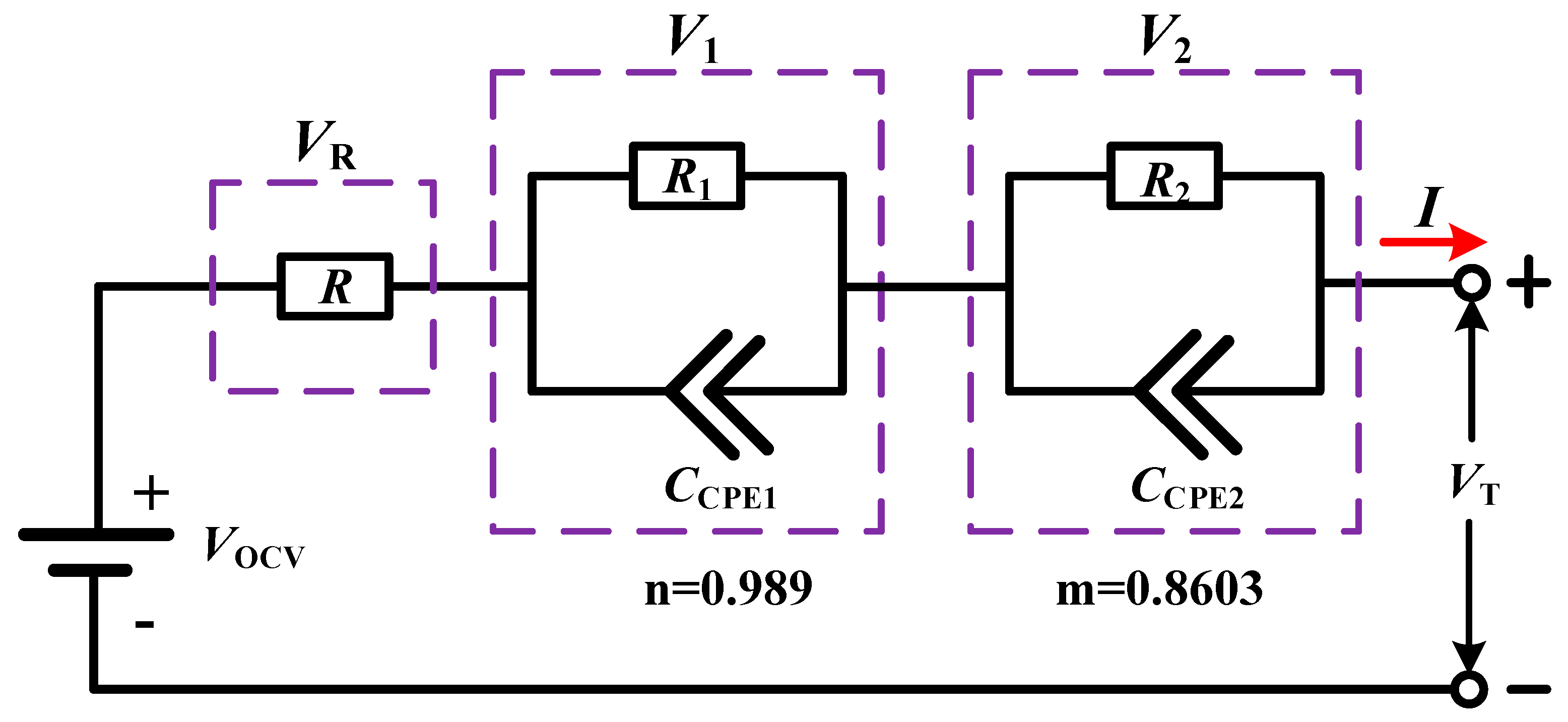
The IOM is not suitable for an accurate description of the battery dynamics, and the order will affect the model’s accuracy. The accuracy of a low-order model is low, but the amount of calculation is also small, whereas the accuracy of a high-order model is high but the amount of calculation is large. A Low- or high-order model is usually selected in accordance with the specific application and requirements. A model established by fractional calculus in the frequency domain possesses better accuracy [55]. The battery has the essence of a FOM when processes are converted from the time domain to the frequency domain. Thus, fractional-order theory can be used to enhance the accuracy of the battery model. The order identification of a battery model based on genetic algorithm optimization takes the minimum error of the model terminal voltage as the objective function, finds the corresponding minimum order, and realizes the optimal estimation of model parameters. The model cannot be extremely complex because presenting the dynamic characteristics clearly by the model is necessary. In the present study, the FOM of a battery is established. This model solves the trade-off between the complexity and accuracy of the battery model, realizes accurate battery modeling, and lays a foundation for SOC estimation. A second-order RC model based on a fractional-order ECM is presented. This model simplifies the model structure so that the amount of calculation is reduced without a loss in the accuracy of the model. Compared to the IOM, the MAE and RMSE of the FOM are reduced, which means that the FOM possesses higher accuracy than the IOM. Figure 2 shows the fractional-order ECM.

2.2.2. Parameter Identification

Parameter Identification of Integer-Order Model

The ECM uses circuit elements—for instance, capacitance, resistance, and constant voltage power supply—to form a circuit network for the description of the battery’s external characteristics. The ECM has good applicability to various working states, and the amount of calculation is relatively small.
According to Kirchhoff’s voltage law, the equation of state can be described as:
{ V ˙ 1 = 1 R 1 C 1 U 1 + 1 C 1 I V ˙ 2 = 1 R 2 C 2 U 2 + 1 C 2 I S O ˙ C = 1 Q n I
where VOCV is the open circuit voltage close to the SOC, I is the current, R, R1, C1, R2, and C2 are the Ohmic resistance, polarization resistance, polarization capacitance, polarization resistance, and polarization capacitance, of resistors 1 and 2 and capacitors 1 and 2, respectively; V1 is the voltage of capacitor C1, and V2 is the voltage of capacitor C2.
The output equation can be written as:
V T = V O C V R I V 1 V 2
where VT is the terminal voltage.
R can be obtained using the equation:
R = | V b V a | + | V d V c | 2 | I |
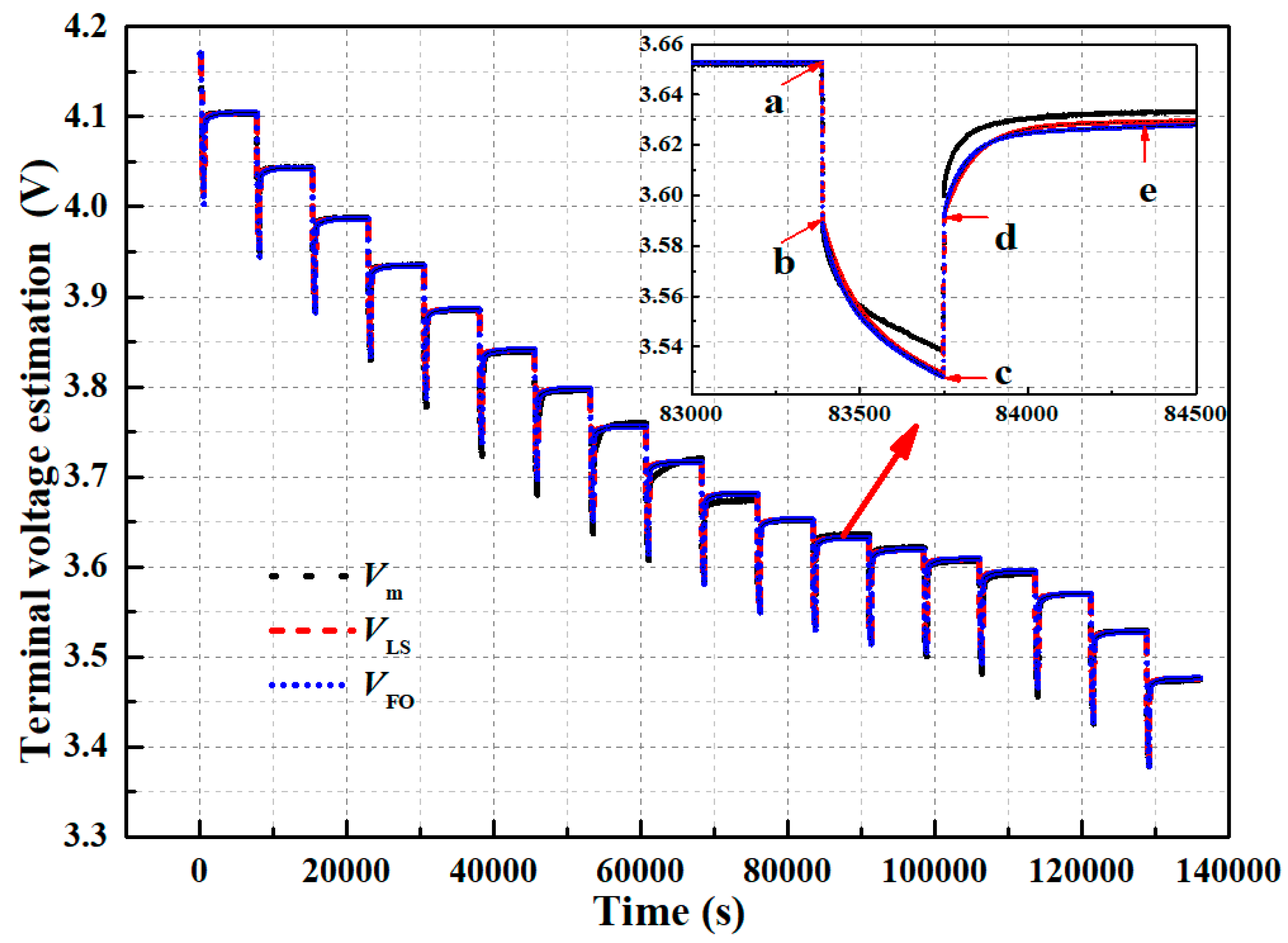
where Va, Vb, Vc, and Vd are the voltage at point a, b, c, and d (as shown in Figure 3), respectively.
The response of an RC circuit with resistance R, capacitance C, and constant current I is crucial for identification and can be described as:
V ( t ) = V ( t 0 ) e t t 0 τ + I R ( 1 e t t 0 τ )
where t0 is the initial time.
The time constants τ1 and τ2 are determined in the relaxation process c-d-e. Voltage V1 and V2 can be written as:
V 1 ( t ) = V 1 ( t c ) e t t c τ 1
V 2 ( t ) = V 2 ( t c ) e t t c τ 2
In accordance with Equation (2), they can be written as:
V ( t ) = V O C V V 1 ( t c ) e t t c τ 1 V 2 ( t c ) e t t c τ 2
This also can be written as:
V T = α 1 α 2 e t t c β 1 α 3 e t t c β 2
where α1 can be obtained after the relaxation process (at point e), and the optimal coefficients α2, α3, β1, and β2 can be obtained by the “Custom Equation” function invoked in MATLAB.
Parameters R1, C1, R2, and C2 can be identified during the battery discharge process a-b-c. The end of the previous relaxation process is at point a, V1(ta) = 0, and V2(ta) = 0. From Equation (4), it can be written as:
V 1 ( t ) = I R 1 ( 1 e t t a τ 1 )
V 2 ( t ) = I R 2 ( 1 e t t a τ 2 )
Resistances R1 and R2 can be obtained from the following formula:
R 1 = V 1 ( t c ) I ( 1 e t c t a τ 1 )
R 2 = V 2 ( t c ) I ( 1 e t c t a τ 2 )
{ τ 1 = R 1 C 1 τ 2 = R 2 C 2 C 1 = τ 1 R 1 C 2 = τ 2 R 2
Table 2 lists the completed identification of the parameters of IOM.

Parameter Identification of Fractional-Order Model

The frequently used fractional-order calculus can be described as follows:
α D t r f ( t ) = lim h 0 h r i = 0 ( t α ) / h ( 1 ) i ( r i ) f ( t i h )
α D t r f ( t ) = { d r f ( t ) / d t r , r > 0 1 , r = 0 α t f ( t ) ( d t r ) , r < 0
where αDtr is a fractional-order calculus operation, α and t are the ceiling and floor values of the integration limits, respectively, and r is the fractional order; h is the step size and is set to 0.1 s, and the value of i is 0, 1, 2....
The capacitive elements C1 and C2 are shown in fractional order, which can be expressed as:
{ Z C 1 ( j ω ) = 1 [ C 1 ( j ω ) ] m Z C 2 ( j ω ) = 1 [ C 2 ( j ω ) ] n
where m and n are the orders of the polarization capacitance and diffusion capacitance, m, nR, 0 ≤ m ≤ 1, and 0 ≤ n ≤ 1.
In accordance with Thevenin’s theorem, the current equation can be written as:
I = C 1 D m V 1 + V 1 R 1 = C 2 D n V 2 + V 2 R 2
V R = I R
The FOM for a Li-ion battery can be expressed as:
{ S O C = S O C 0 1 Q n t 0 t I d t I = C 1 D m V 1 + V 1 R 1 = C 2 D n V 2 + V 2 R 2 V T = V O C V R I V 1 V 2
The state-space equation of the FOM can be written as:
{ D α x = A x + B I y = C x + D I
where A = [ T s / ( R 1 C 1 ) T s / ( R 2 C 2 ) 0 ] , B = [ T s / C 1 T s / C 2 T s / Q n ] , x = [ V 1 V 2 SOC ] , C = [−1 −1 0]; D = [−R0]; α = [m n 1]; Qn is the rated capacity of the lithium battery.

2.3. UKF and Multi-Information

The UKF algorithm proceeds as follows [56]:
(1) The initial value of state is x 0 and the initial value of a posteriori state error covariance is P 0 .
x ^ 0 = E [ x 0 ]
P 0 = E [ ( x 0 x ^ 0 ) ( x 0 x ^ 0 ) T ]
(2) Calculate the sampling points.
{ x k 0 = x ^ k x k i = x k + ( L + λ ) P k 1 , i = 1 L x k i = x k ( L + λ ) P k 1 , i = L + 1 2 L
where L is the length of the state vector.
The weight value is expressed as:
{ λ = α 2 ( L + k i ) L W m 0 = λ L + λ , W m i = 1 2 ( L + λ ) , i = 1 2 L W c 0 = λ L + λ + 1 α 2 + β , W c i = 1 2 ( L + λ ) , i = 1 2 L
(3) Update the a priori state x ¯ k + 1 and system variance prediction P x x .
x ¯ k + 1 = i = 0 2 L W m i x k i
P x x = i = 0 2 L ( W c i ( x k i x ¯ k + 1 ) ( x k i x ¯ k + 1 ) T ) + Q k
where Q k is the noise covariance matrix.
(4) Update the observed value of y ^ k + 1 and the predicted value of observed variance P y y .
y ^ k + 1 = i = 0 2 L W m i y k i
P y y = i = 0 2 L ( W c i ( y k i y ^ k + 1 ) ( y k i y ^ k + 1 ) T ) + R k
(5) Update the covariance Pxy, a posteriori state value x ^ k + 1 , and a posteriori state error covariance P k .
P x y = i = 0 2 L W c i ( x k i x ¯ k + 1 ) ( y k i y ^ k + 1 ) T
K k = P x y P y y
x ^ k + 1 = x ¯ k + 1 + K k ( y k + 1 y ^ k + 1 )
P k = P x x K k P x y T
A single innovation of SOC estimation by the UKF can be expressed as:
e k = y k y ^ k = V T , k V O C V , k + I R 0 , k + U 1 , k + U 2 , k
The multi-information matrix is as follows [39]:
E p , k = [ e k e k 1 e k p + 1 ] = [ y k y ^ k y k 1 y ^ k 1 y k p y ^ k p + 1 ]
where p is the information length.
The Kalman filter gain (K) is extended to the gain matrix and the specific formula is:
K p , k = [ K x , k K x , k 1 K x , k p + 1 ]
The state variable estimating update is written as:
x k = x ¯ k / k 1 + K p , k E p , k
The covariance update is expressed as:
P x x , k = P x x , k / k 1 K x , k P y , k / k 1 K T x , k
The FOM parameters identified by the AGA are the optimal solutions for the whole pulse discharge process. Table 3 presents the parameter identification results.
Figure 3 shows the estimation of the terminal voltage by the IOM and FOM compared to the experimental data. The obtained experimental data are used as model inputs to obtain the terminal voltage at the output of the model. Then, the terminal voltages obtained at the output of the IOM and FOM are analyzed respectively.
As a measure for difference evaluation between the predicted and measured values of a model, RMSE is frequently used. The lower the RMSE value, the higher the accuracy of the prediction result. Similarly, MAE stands for the mean value of the absolute error between the predicted and measured values, which can better reflect the prediction error. A lower MAE means a better prediction result.
RMSE = i = 1 N ( x i x i ) 2 N
where xi stands for the estimation value and x i stands for the experimental value.
MAE = i = 1 N | x i x i | N
Table 4 lists the calculated MAE and RMSE of the IOM and FOM. The MAE and RMSE estimation results of the FOM are 0.0026 and 0.0205 V, respectively. The MAE and RMSE estimation results of the IOM are 0.0027 and 0.024 V, respectively. The MAE of FOM is lower than that of the IOM by 0.0001 V, and the RMSE is lower than that of the IOM by 0.0035 V.
Figure 4 presents a comparison of the estimation errors in the terminal voltage between the FOM and IOM. The terminal voltage error is lower with FOM than with IOM, which means that the former can track the experimental value well. The FOM possesses higher accuracy in tracking the terminal voltage, with lower error. The FOM can achieve a more precise reflection of the real situation of the battery than the IOM.

3. Experimental Validation and Discussion

3.1. SOC Estimation

3.1.1. FTP75

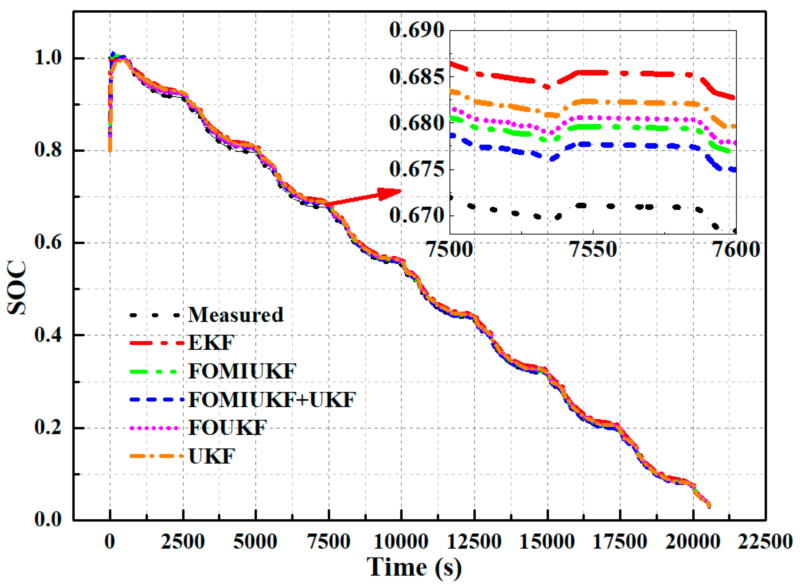
Under the same conditions (SOC initial value is 0.8), the battery SOC under the discharge condition laid out in FTP75 is estimated using EKF, UKF, FOUKF (fractional-order unscented Kalman filter) single estimation algorithms, and the FOMIUKF, and FOMIKUKF + UKF joint estimation algorithms, and then the results are compared with the SOC reference value. The results are shown in Figure 5. The EKF linearizes the state-space equation using the Taylor formula and only retains the linear term, which reduces the estimation accuracy. The UKF adopts a filter unscented transformation, thereby avoiding the linearization process and improving the estimation precision. Therefore, compared to the EKF algorithm, the SOC estimation of the UKF algorithm possesses higher accuracy. The SOC estimation value corresponding to the FOM method possesses higher accuracy than that of the IOM methods due to the higher accuracy of the FOM method. The MI method is a product of the processing of an iterative algorithm. This method is used to predict the error information and make the a posteriori correction more accurate. The combination of MI and UKF is helpful to improve the precision of the algorithm. Therefore, the estimation of SOC using FOMIUKF is more accurate. The SOC is closely related to the capacity. After obtaining a relatively precise SOC value, the capacity can be determined in accordance with the SOC value, and then the SOH calibration can be completed. With the change in SOH, the capacity is dynamic. Thus, the capacity value utilized in SOC estimation is dynamic. A coupling relationship is found between SOC and SOH. Thus, the SOC and SOH algorithms have an interdependent relationship. The design of a SOC–SOH cooperative estimation algorithm is the basis to achieve accurate SOC estimation under complex and changeable real vehicle conditions. Under the model parameters, the five algorithms can effectively track the reference value of SOC, with the best tracking effect possessed by the algorithm proposed in this study. Hence the proposed FOMIUKF + UKF algorithm has the highest SOC estimation accuracy.
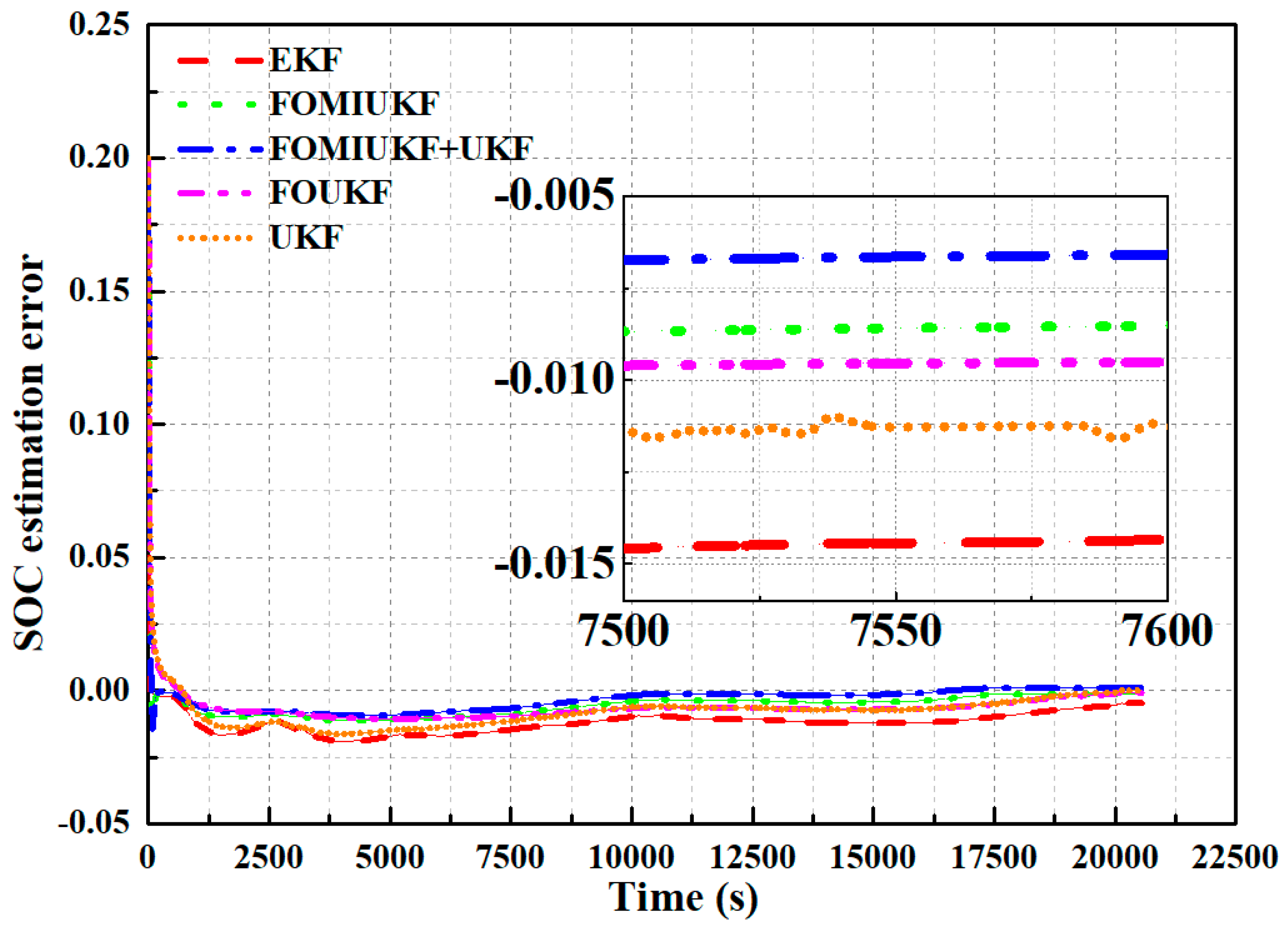
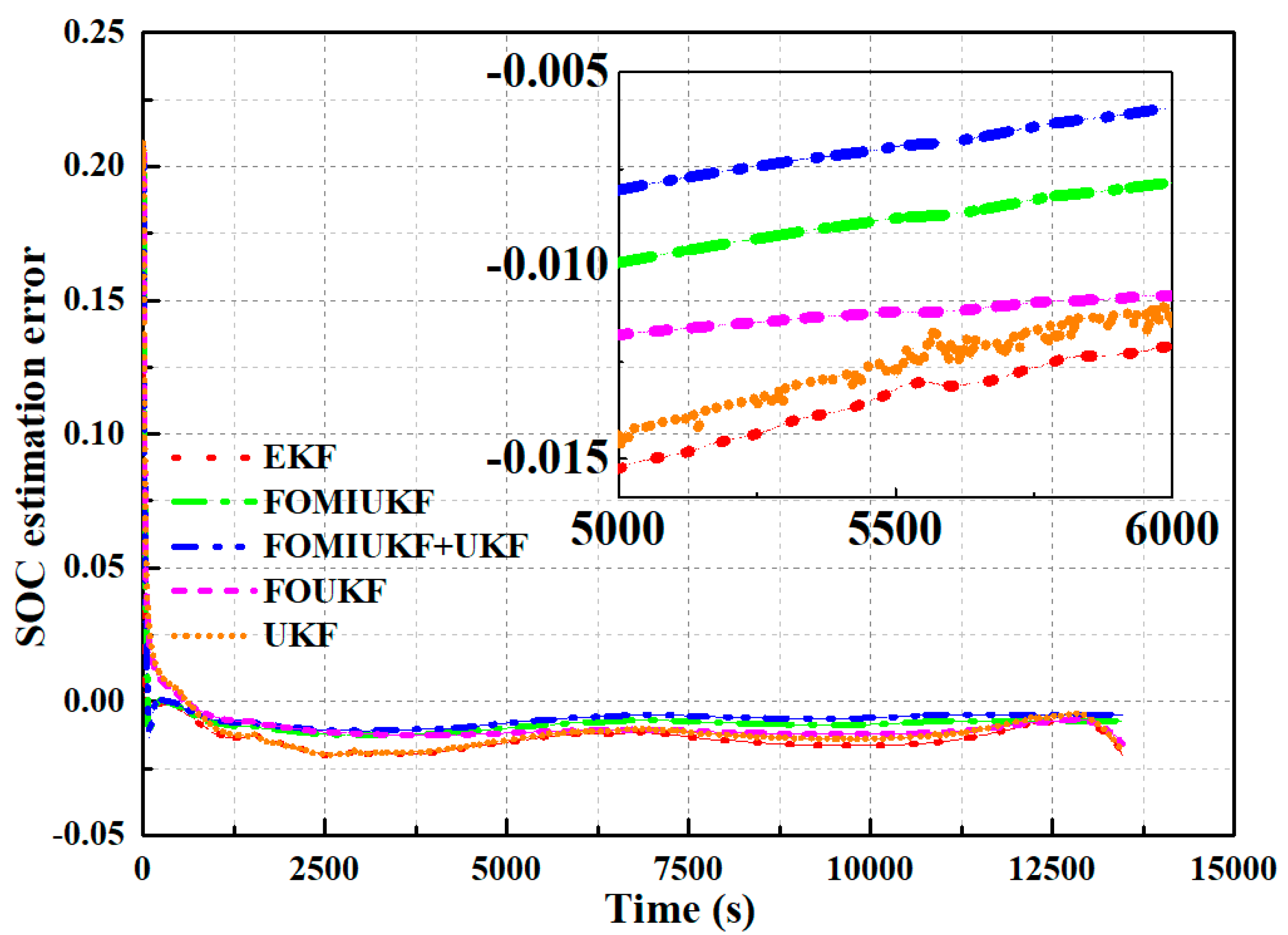
Figure 6 presents the SOC estimation errors of the five studied algorithms under the model parameters. For SOC estimation, under the discharge condition of FTP75, the MAE and RMSE of the EKF algorithm are 2.19% and 1.2%, respectively. The MAE and RMSE of the UKF are 1.66% and 0.84%, respectively. The MAE and RMSE of the FOUKF are 1.13% and 0.69%, respectively. The MAE and RMSE of the FOMIUKF are 1.05% and 0.57%, respectively. The MAE and RMSE of the FOMIUKF + UKF are 0.94% and 0.39%, respectively. Therefore, the proposed joint estimation algorithm of FOMIUKF + UKF has the highest SOC estimation accuracy.

3.1.2. Japan

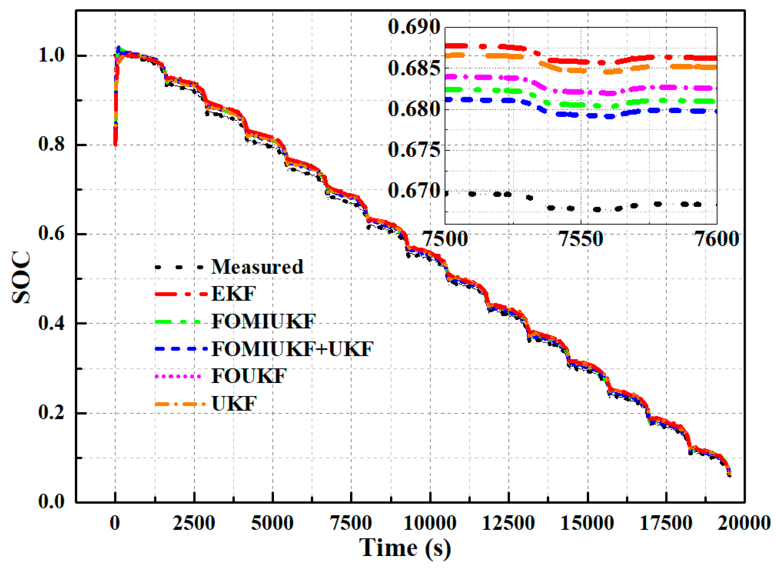
Under the same conditions (SOC initial value is 0.8), the EKF, UKF, FOUKF, FOMIUKF, and FOMIUKF + UKF estimating algorithms are utilized for SOC estimation of a single battery with a discharge under Japanese regulatory test conditions, and then compared with the SOC reference value. The results are shown in Figure 7. The five algorithms can effectively track the SOC reference value, and the proposed FOMIUKF + UKF algorithm achieved the best tracking effect among the algorithms. From the enlarged view in Figure 7, the EKF algorithm has the least precision of SOC estimation, while the proposed algorithm has the best. The order of SOC estimation accuracy of the five estimation algorithms ranked from low to high is SOCEKF < SOCUKF < SOCFOUKF < SOCFOMIUKF < SOCFOMIUKF+UKF.
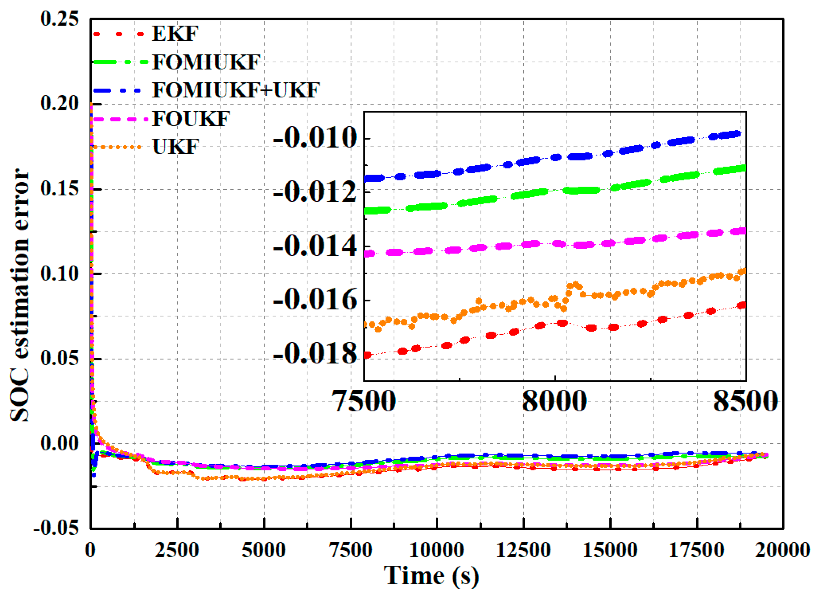
Figure 8 presents the SOC estimation errors of the five studied algorithms under the model parameters. Under the Japanese regulatory discharge conditions, from the figure, the MAE and RMSE of the EKF algorithm are 2.01% and 1.39%, respectively. The MAE and RMSE of the UKF are 2.01% and 1.28%, respectively. The MAE and RMSE of the FOMUKF are 1.6% and 1.05%, respectively. The MAE and RMSE of the FOMIUKF are 1.25% and 0.88%, respectively. The MAE and RMSE of the FOMIUKF + UKF are 1.09% and 0.68%, respectively. Hence, the FOMIUKF + UKF joint estimating algorithm possesses the best SOC estimation accuracy.

3.1.3. NEDC

Under the same conditions (SOC initial value is 0.8), the EKF, UKF, FOUKF, FOMIUKF, FOMIUKF + UKF estimation algorithms are utilized for the SOC estimation of a single battery under NEDC discharge conditions and then compared with the SOC reference value. The results are presented in Figure 9. Under the model parameters, the five algorithms can achieve effective tracking of the SOC reference value, and the FOMIUKF + UKF algorithm possesses the best tracking effect. From the enlarged view in Figure 9, the EKF algorithm has the worst effect on SOC estimation, while the algorithm proposed in the present study achieves the best tracking effect. The order of SOC estimation accuracy of the five estimation algorithms ranked from low to high is SOCEKF < SOCUKF < SOCFOUKF < SOCFOMIUKF < SOCFOMIUKF+UKF.
Figure 10 presents the SOC estimation errors of the five studied five algorithms under the model parameters. Under the NEDC discharge condition, from the figure, the MAE and RMSE of the EKF algorithm for SOC estimation are 2.12% and 1.51%, respectively. The MAE and RMSE of the UKF for SOC estimation are 2.09% and 1.38%, respectively. The MAE and RMSE of the FOMUKF for SOC estimation are 1.48% and 1.2%, respectively. The MAE and RMSE of the FOMIUKF for SOC estimation are 1.45% and 1.01%, respectively. The MAE and RMSE of the FOMIUKF + UKF for SOC estimation are 1.35% and 0.88%, respectively. Thus, the FOMIUKF + UKF joint estimation algorithm possesses the highest SOC accuracy of the five algorithms.

3.1.4. WLTC

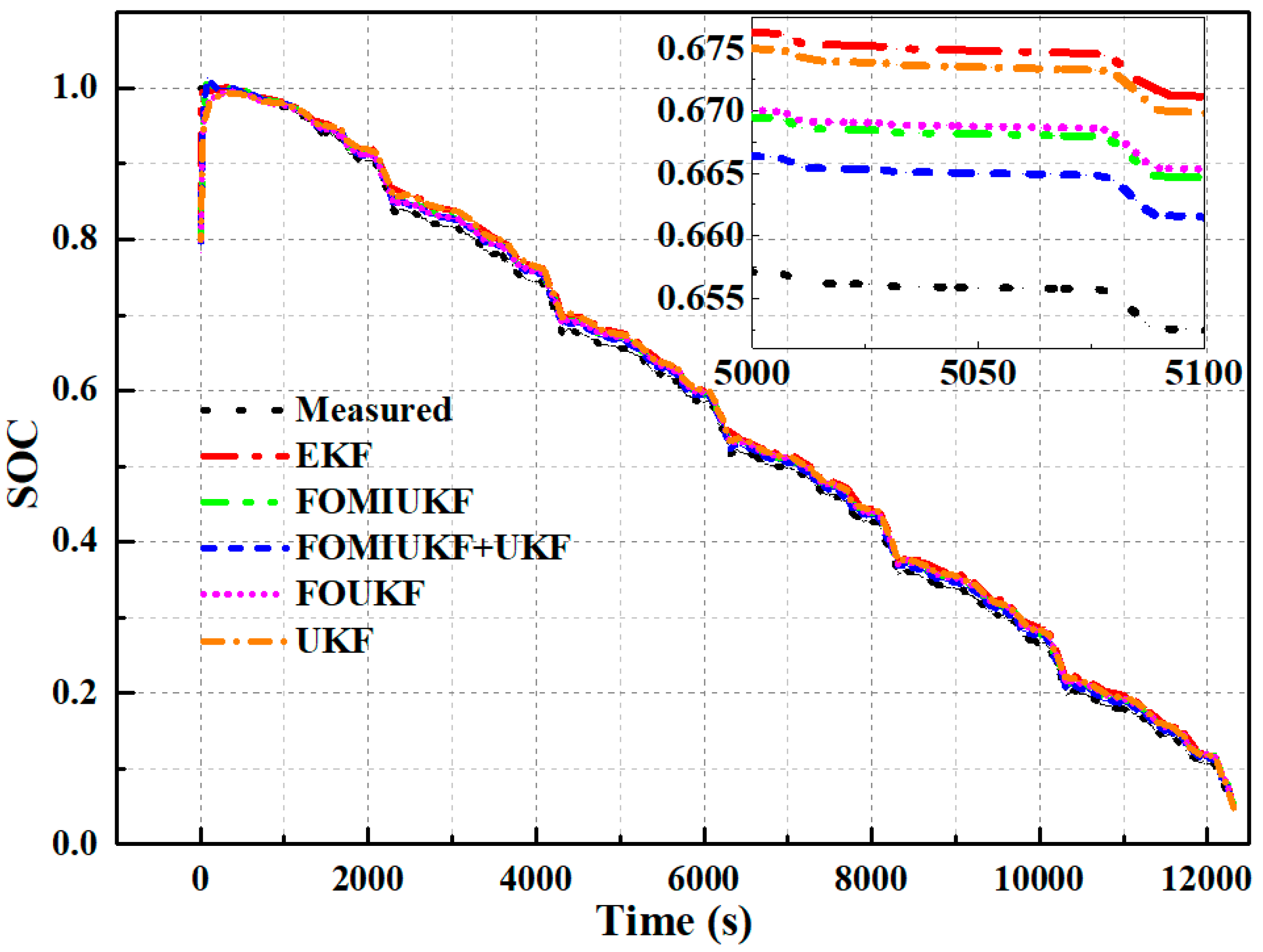
Under the same conditions (SOC initial value is 0.8), the EKF, UKF, FOUKF, FOMIUKF, and FOMIUKF + UKF estimation algorithms are utilized for the SOC estimation of a single battery under WLTC discharge conditions and then compared with the SOC reference value. The results are shown in Figure 11. The five algorithms can achieve effective tracking of the SOC reference value, and the proposed FOMIUKF + UKF algorithm has the best tracking effect. From the enlarged view in Figure 11, the EKF algorithm has the worst effect on SOC estimation, while the best tracking effect is achieved by the algorithm proposed in the present study. The order of SOC estimation accuracy of the five estimation algorithms ranked from low to high is SOCEKF < SOCUKF < SOCFOUKF < SOCFOMIUKF < SOCFOMIUKF+UKF.
Figure 12 presents the SOC estimation errors of the five studied algorithms under the model parameters. Under WLTC discharge conditions, the MAE and RMSE of the EKF algorithm for SOC estimation are 1.69% and 2.25%, respectively. The MAE and RMSE of the UKF for SOC estimation are 1.53% and 2.25%, respectively. The MAE and RMSE of the FOUKF for SOC estimation are 1.16% and 1.44%, respectively. The MAE and RMSE of the FOMIUKF for SOC estimation are 1.09% and 1.38%, respectively. The MAE and RMSE of SOC estimation by the FOMIUKF + UKF are 0.76% and 1.08%, respectively. Thus, the proposed FOMIUKF + UKF joint estimating algorithm has the highest SOC estimation accuracy.
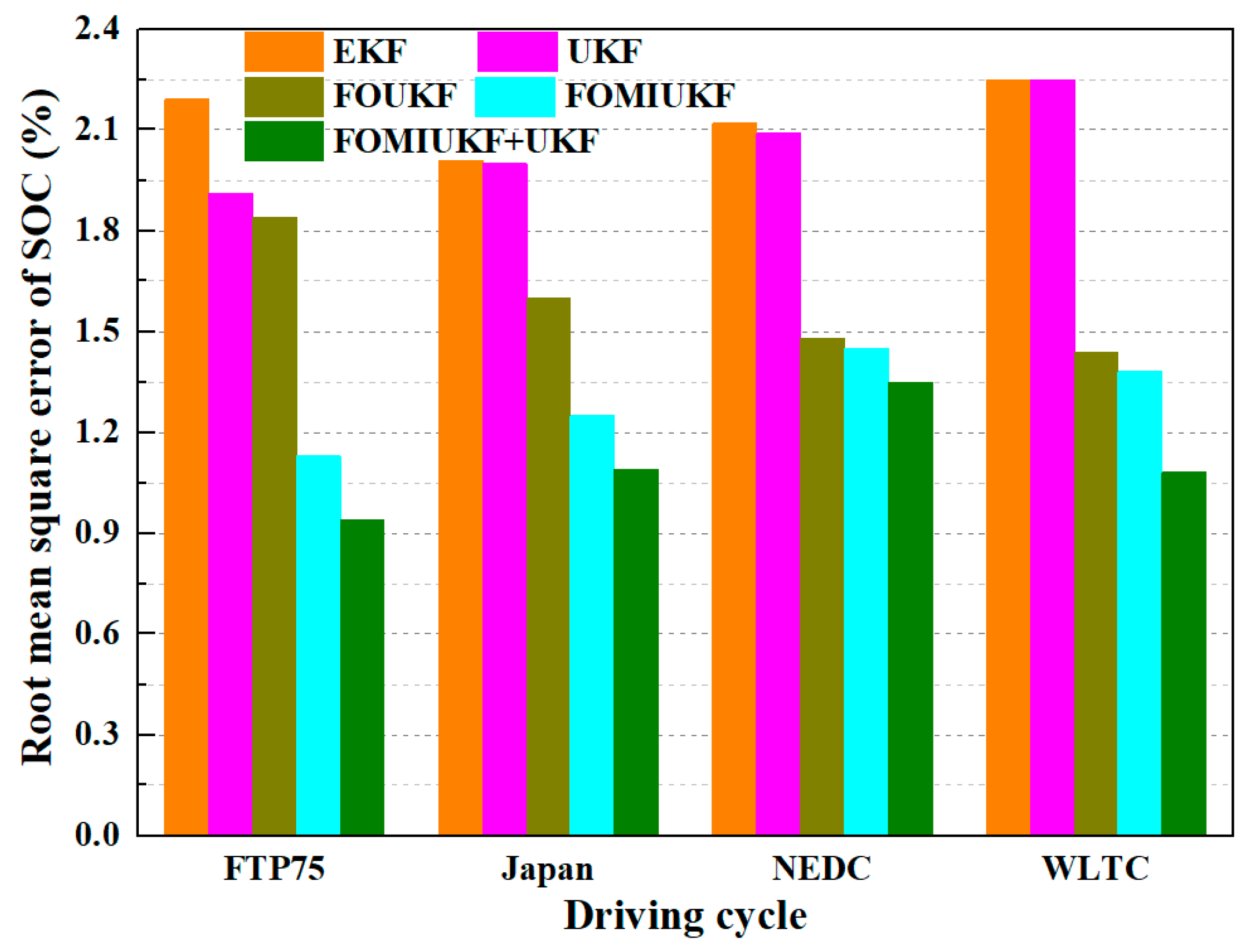
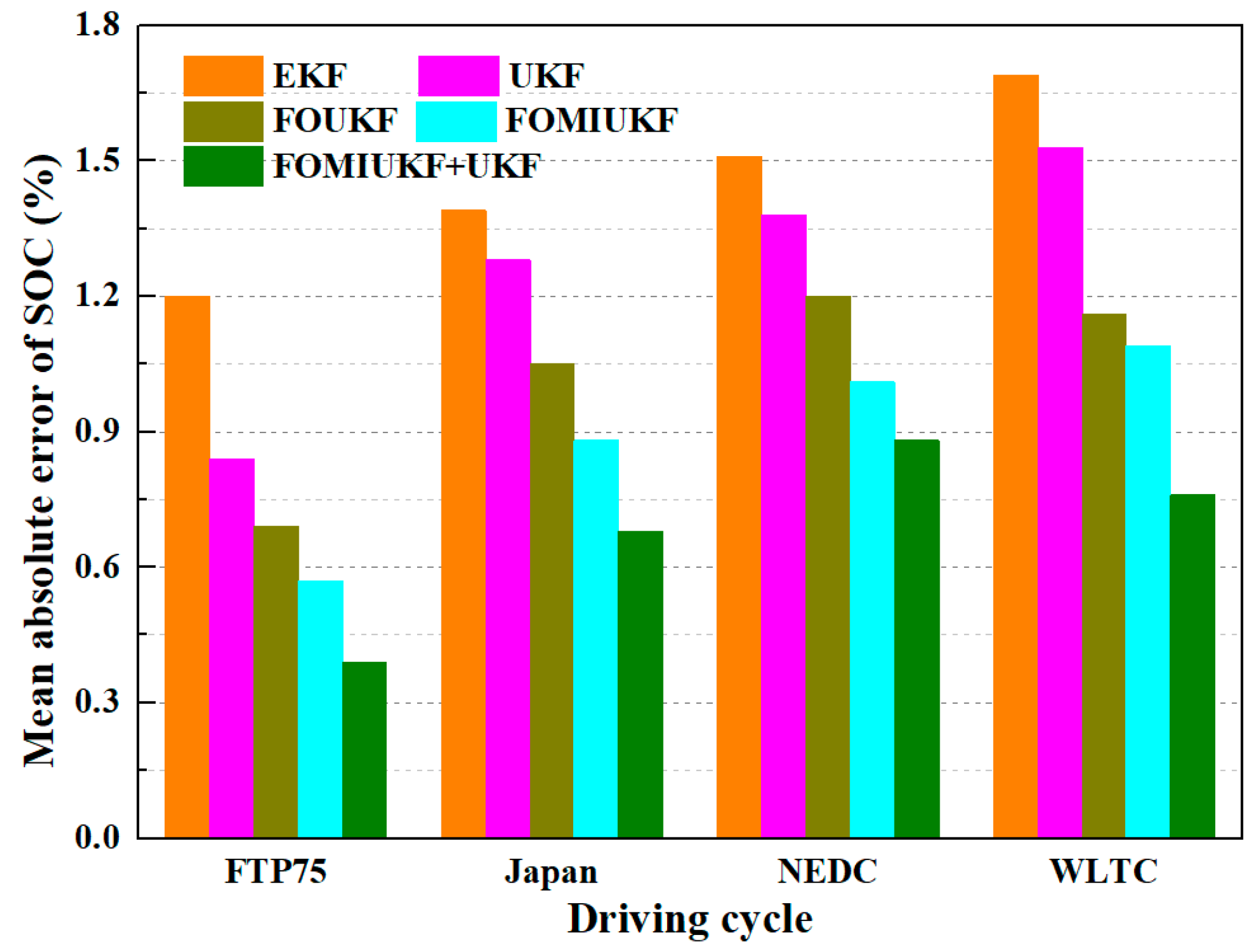
The MAE and RMSE corresponding to the SOC estimates among the EKF, UKF, FOUKF, FOMIUKF, and FOMIUKF + UKF algorithms for different operating conditions are shown in Figure 13 and Table 5. As shown in Figure 13, whether it is in MAE or RMSE, the proposed joint estimation method can achieve the best results, thereby proving its effectiveness.

3.2. Terminal Voltage Estimation

3.2.1. FTP75

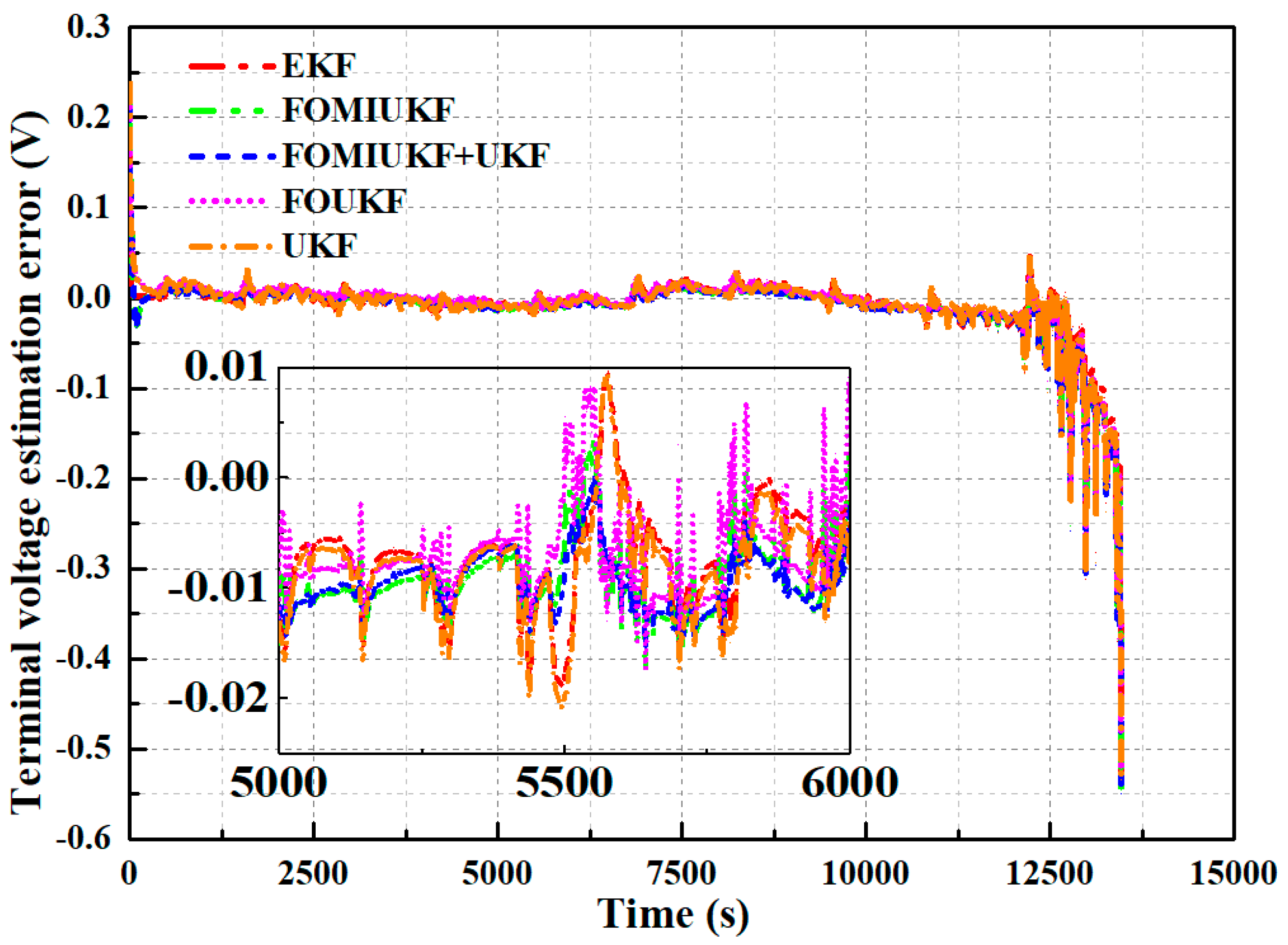
The terminal voltage of the battery measured in this test is compared with that outputted by models corresponding to the five studied algorithms. The results are shown in Figure 14. Under the working condition of FTP75, the terminal voltage output of models that correspond to the five algorithms is extremely close to the measured voltage, with an MAE value not exceeding 10 mV, which precisely simulates the battery dynamic characteristics. However, the prediction error in the terminal voltage is obviously large at the end of the FTP75 working condition, which may be related to the nonlinearity of batteries at low SOC. The relatively large MAE in the terminal voltage at the end of discharge may be caused by the unstable internal chemical structure of the battery during this period.
Figure 15 shows a comparison of terminal voltage errors generated by the models of the five studied algorithms under FTP75 working conditions. Under the discharge condition of FTP75, the MAE values corresponding to the EKF, UKF, FOUKF, FOMIUKF, and FOMIUKF + UKF algorithms are 0.0084, 0.0083, 0.008, 0.008, and 0.0078 V, respectively. Under FTP75 conditions, the proposed method is more accurate than the other algorithms.

3.2.2. Japan

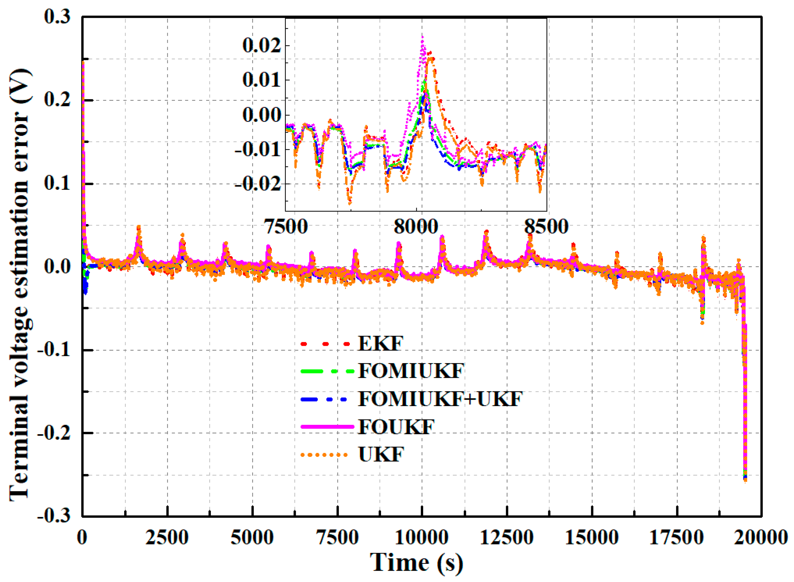
The terminal voltage of the battery measured in this test is compared with that outputted by models corresponding to five studied algorithms. The results are presented in Figure 16. Under the Japanese regulatory test working conditions, the terminal voltage output of the model corresponding to the five algorithms is extremely close to the measured voltage, and the MAE is less than 20 mV, showing a good simulation of battery dynamic characteristics. At the end of the Japanese regulatory test working conditions, the prediction error in the terminal voltage is obviously large, which may be related to the nonlinearity of batteries at low SOC. The relatively large MAE in the terminal voltage at the end of discharge may be caused by the unstable internal chemical structure of the battery during this period.
Figure 17 shows a comparison of the error in the terminal voltage of models corresponding to five studied algorithms under the Japanese regulatory test working conditions. Under the Japanese regulatory test discharge conditions, the MAE values corresponding to the EKF, UKF, FOUKF, FOMIUKF, and FOMIUKF + UKF algorithms are 0.0163, 0.0159, 0.0158, 0.0157, and 0.0153 V, respectively. Under the Japanese regulatory test working conditions, the proposed method is more accurate than the other algorithms.

3.2.3. NEDC

The terminal voltage of the battery measured experimentally is compared with the voltage output of the models corresponding to the five studied algorithms, and the results are shown in Figure 18. Under the NEDC condition, the terminal voltages of the models corresponding to the five algorithms are extremely close to the measured voltages with the MAE values not exceeding 10 mV, demonstrating a good simulation of the battery’s dynamic characteristics. However, the prediction error of the terminal voltage is obviously large at the end of the NEDC conditions, which may be related to the nonlinearity of batteries at low SOC. The relatively large MAE in the terminal voltage at the end of discharge may be caused by the internal chemical structure instability of the battery during this period.
Figure 19 shows a comparison of the error in the terminal voltage of the models corresponding to the five algorithms and the actual terminal voltage measured in the test under NEDC working conditions. Under NEDC discharge conditions, the MAE values corresponding to the EKF, UKF, FOUKF, FOMIUKF, and FOMIUKF + UKF algorithms are 0.0089, 0.0086, 0.00081, 0.0078, and 0.0076 V, respectively. Under NEDC conditions, the proposed method is more accurate than the other algorithms.

3.2.4. WLTC

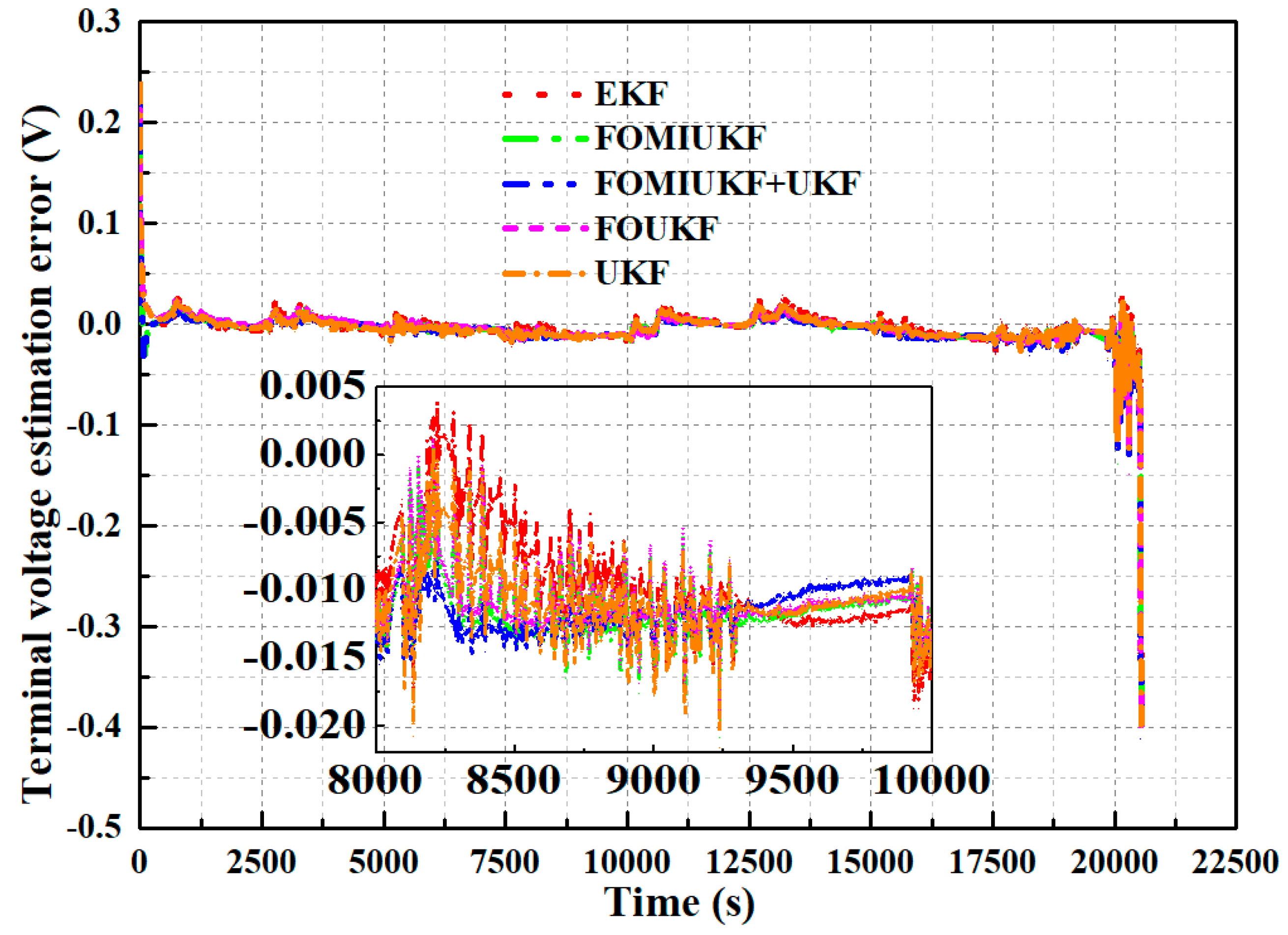
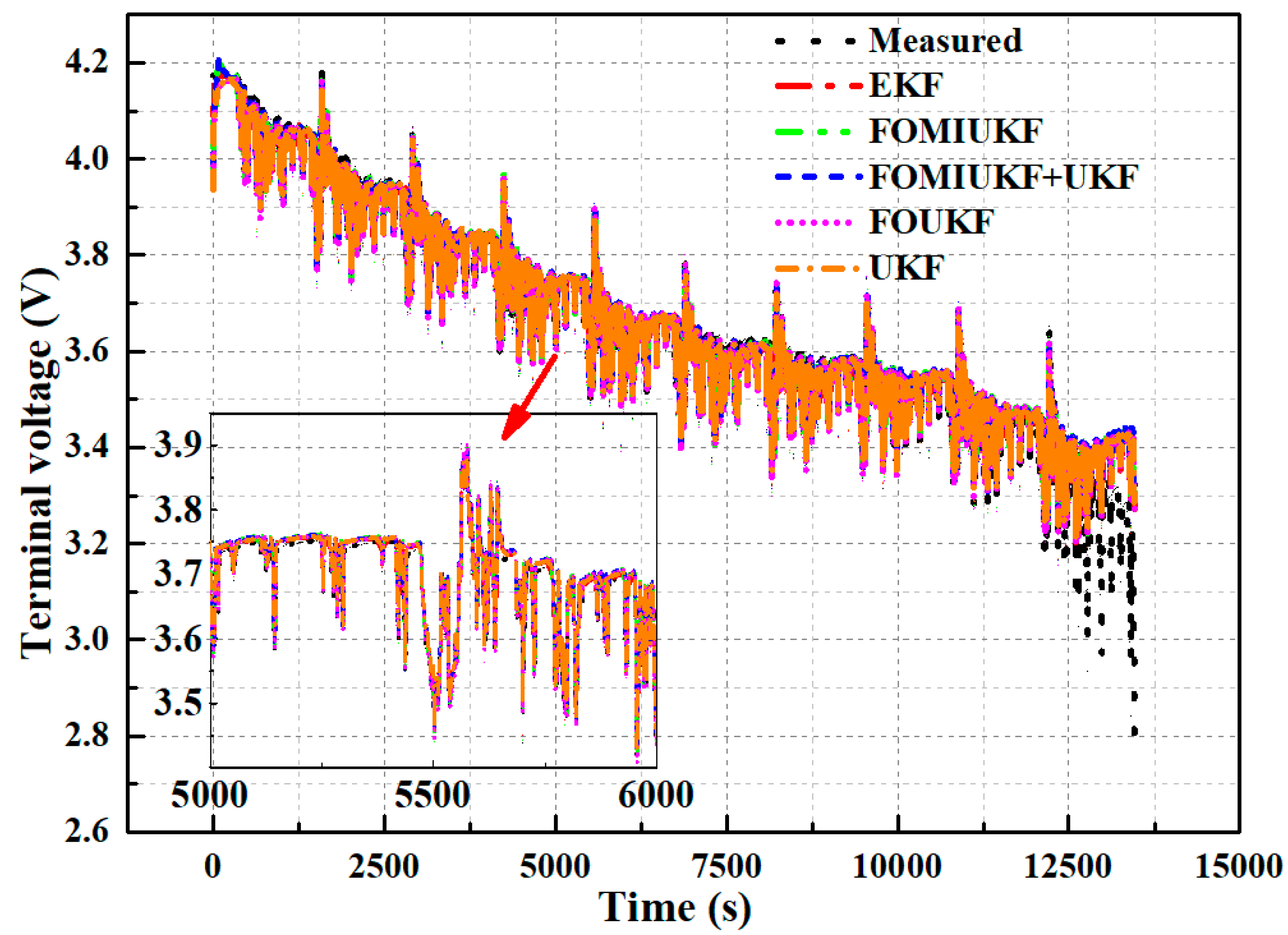
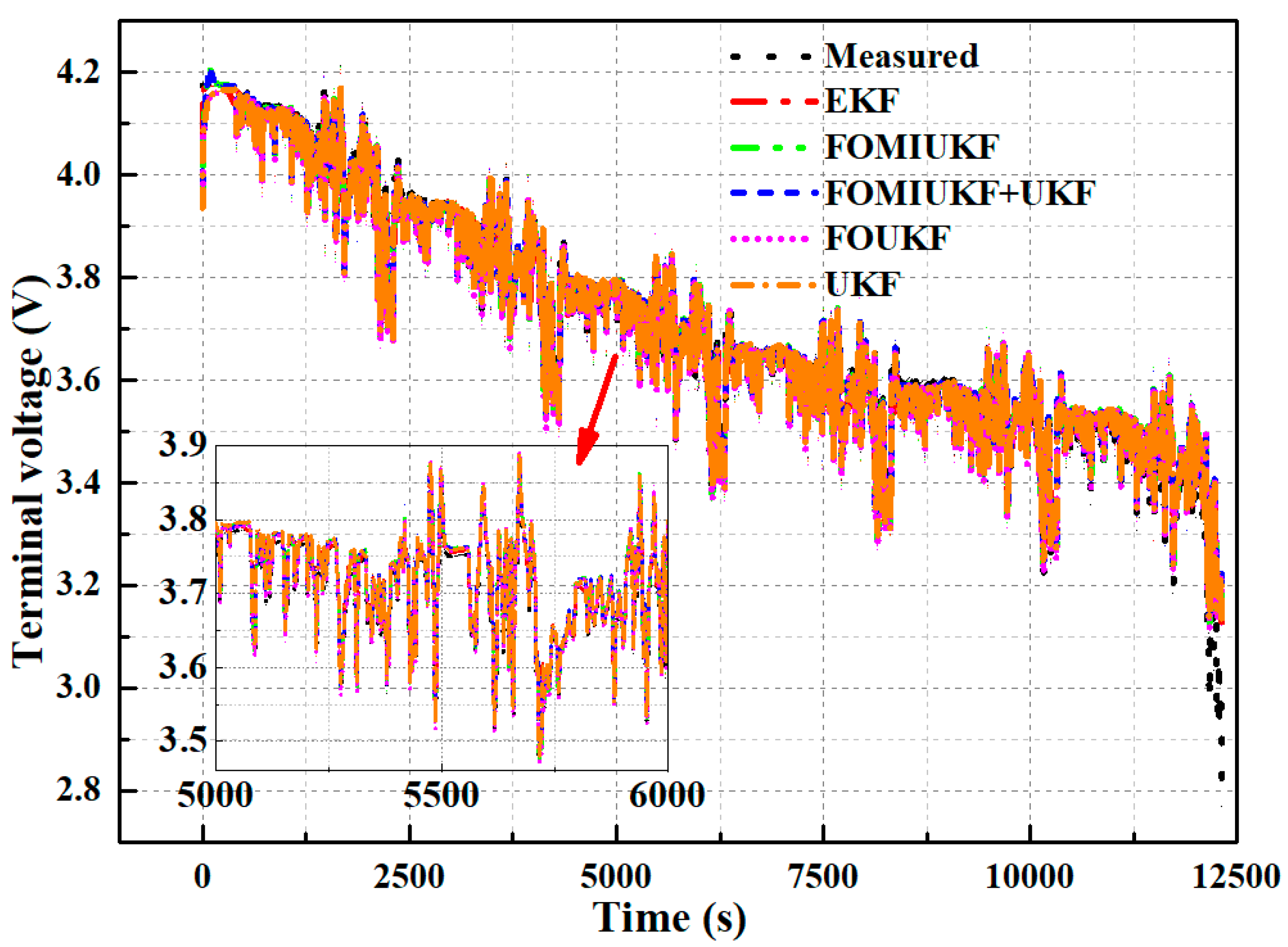
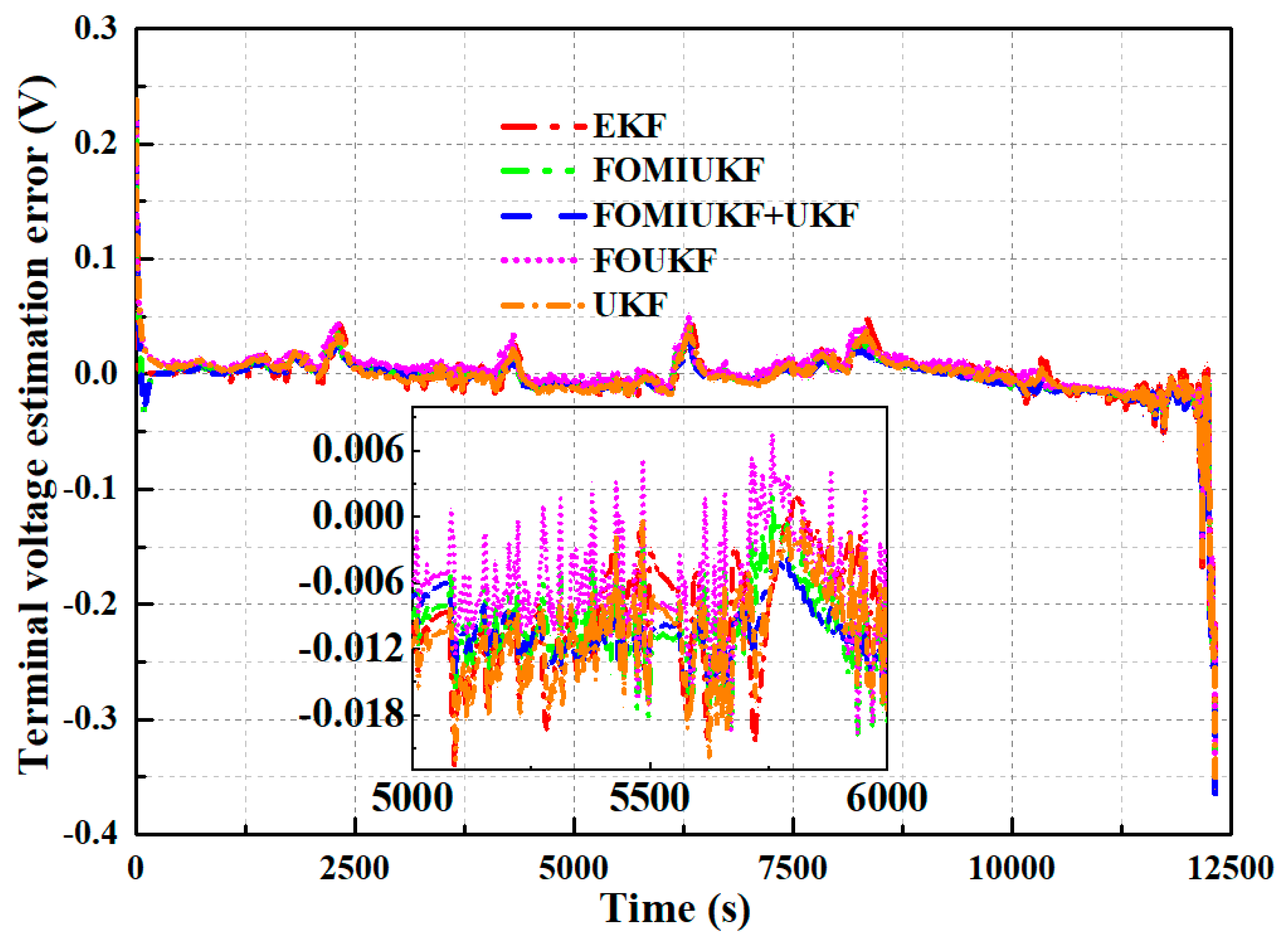
The terminal voltage of the battery measured in the test is compared with that outputted by models corresponding to the five studied algorithms. The results are presented in Figure 20. Under WLTC conditions, the terminal voltage of the model output corresponding to the five algorithms is extremely close to the measured voltage, and the MAE is less than 20 mV, demonstrating a good simulation of the battery’s dynamic characteristics. The prediction error in the terminal voltage is obviously large by the end of the WLTC working conditions, which may be related to the nonlinearity of the battery at low SOC. The relatively large average absolute error in the terminal voltage at the end of discharge may be caused by the unstable internal chemical structure of the battery during this period.
Figure 21 shows a comparison of the error in the terminal voltage of the models corresponding to the five algorithms under WLTC working conditions. Under WLTC discharge conditions, the average absolute errors corresponding to the EKF, UKF, FOUKF, FOMIUKF, and FOMIUKF + UKF algorithms are 0.0117, 0.0116, 0.0114, 0.0107, and 0.0102 V, respectively. Under WLTC conditions, the proposed method is more accurate than the other algorithms.

3.3. SOH Estimation

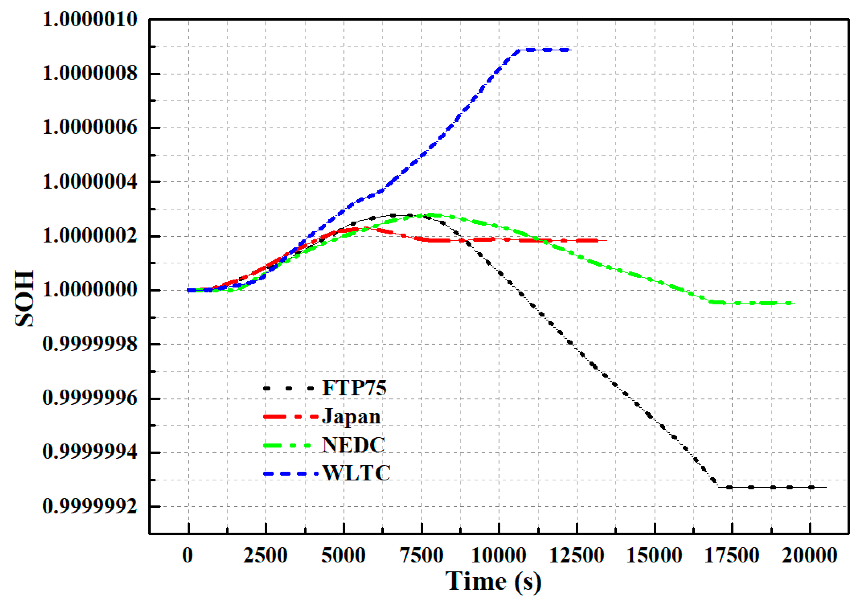
The battery used in this study is new, and the current maximum available capacity is measured by the capacity test and set as the reference value. The SOH of the battery is obtained by dividing the current maximum available capacity by the rated capacity. Thus, assuming the initial value of the SOH is 1, the change curve of the SOH of the battery under different working conditions is shown in Figure 22.

4. Summary and Conclusions

This study establishes a FOM of a battery and proposes a joint estimation algorithm that can be utilized in SOC and SOH based on multiple timescales to maximize the utilization of battery power, prolong battery service life, as well as improve the efficiency of electric vehicle energy management. The proposed joint estimation algorithm is experimentally validated under different dynamic operating conditions. The main conclusions that can be drawn are the following:
(1) The use of the FOM achieves a great reduction in the computational complexity of excessive RC modules and enhances the accuracy of the battery model. The FOM has reduced MAE and RMSE compared with an IOM, which demonstrates that the FOM possesses a higher accuracy than the IOM.
(2) MI combined with a Kalman filter based on FOM is used to propose a FOMIUKF based on fractional order for the enhancement of SOC estimation accuracy.
(3) A joint estimation algorithm of SOC and SOH based on multiple timescales is established to increase SOC estimation accuracy and reduce computational effort.
(4) The proposed joint algorithm is experimentally validated under different dynamic working conditions. From the experimental results, the proposed joint estimation algorithm possesses high estimation accuracy with an MAE of less than 1% and RMSE of 1.35%.

Author Contributions

Conceptualization, Y.X. and H.Z.; Methodology, Y.X., H.Z. and C.L.; software, Y.X., X.W., F.Y. and L.M.; validation, C.L. and X.W.; formal analysis, L.M. and Y.W.; Investigation, Y.W. and L.M.; resources, H.Z. and F.Y.; Validation, Y.X. and H.Z.; Writing—Original Draft. Y.X. and H.Z.; Investigation, L.M. and Y.W.; visualization, F.Y. and Y.W.; Supervision, X.W.; project administration, C.L. and X.W.; funding acquisition, H.Z. and X.W. All authors have read and agreed to the published version of the manuscript.

Funding

This work was sponsored by the Beijing Natural Science Foundation (Grant No. 3222024), Tianjin Science and Technology Committee (Grant No. 19YFZCGX00060), and supported by the State Key Laboratory of Engines, Tianjin University (Grant No. K2020-08). The authors would like to express their sincere appreciation to the editors and reviewers for their valuable comments on this research.

Institutional Review Board Statement

Not applicable.

Informed Consent Statement

Informed consent was obtained from all subjects involved in the study.

Data Availability Statement

Data are available upon request.

Conflicts of Interest

The authors declare no conflict of interest.

Nomenclature

VVoltage (V)
Rresistance (Ω)
Ccapacitance (F)
Vmmeasured voltage (V)
VLSEstimation voltage with least square integer-order model (V)
VFOEstimation voltage with fractional-order model (V)
FOMfractional-order model
IOMinteger-order model
SOCstate of charge
SOHstate of health
EKFextended Kalman filter
UKFunscented Kalman filter
MImulti-innovation
RULremaining useful life
EVMequivalent circuit model
OCVopen circuit voltage
RMSEroot mean squared error
MAEmean absolute error
AGAadaptive genetic algorithm
LSleast square
FOUKFfractional-order model unscented Kalman filter
FOMIUKFfractional-order model multi-innovation unscented Kalman filter

References

  1. Huo, W.; Li, W.; Zhang, Z.; Sun, C.; Zhou, F.; Gong, G. Performance prediction of proton-exchange membrane fuel cell based on convolutional neural network and random forest feature selection. Energy Convers. Manag. 2021, 243, 114367. [Google Scholar] [CrossRef]
  2. Xu, Y.; Zhang, H.; Yang, F.; Tong, L.; Yang, Y.; Yan, D.; Wang, C.; Ren, J.; Wu, Y. Experimental study on small power generation energy storage device based on pneumatic motor and compressed air. Energy Convers. Manag. 2021, 234, 113949. [Google Scholar] [CrossRef]
  3. Wang, B.; Yu, X.; Xu, H.; Wu, Q.; Wang, L.; Huang, R.; Li, Z.; Zhou, Q. Scenario analysis, management, and optimization of a new Vehicle-to-Micro-Grid (V2μG) network based on off-grid renewable building energy systems. Appl. Energy 2022, 325, 119873. [Google Scholar] [CrossRef]
  4. Zhang, S.; Hao, X.; Chen, Y.; Wu, J. Thermodynamic study on power and refrigeration cogeneration Kalina cycle with adjustable refrigeration temperature. Int. J. Refrig. 2021, 131, 706–713. [Google Scholar] [CrossRef]
  5. Gao, Y.; Wang, X.; Shu, G.; Tian, H.; Shi, X. Applicability analysis of waste heat recovery technology and strategy exploration for hybrid electric vehicles under diverse road conditions. Energy Convers. Manag. 2021, 230, 113780. [Google Scholar] [CrossRef]
  6. Xu, Y.; Zhang, H.; Yang, F.; Tong, L.; Yan, D.; Yang, Y.; Ren, J.; Ma, L.; Wang, Y. State of charge estimation of supercapacitors based on multi-innovation unscented Kalman filter under a wide temperature range. Int. J. Energy Res. 2022, 46, 16716–16735. [Google Scholar] [CrossRef]
  7. Shrivastava, P.; Soon, T.; Idris, M.; Mekhilef, S. Overview of model-based online state-of-charge estimation using Kalman filter family for lithium-ion batteries. Renew. Sustain. Energy Rev. 2019, 113, 109233. [Google Scholar] [CrossRef]
  8. Yang, B.; Wang, J.; Cao, P.; Zhu, T.; Shu, H.; Chen, J.; Zhang, J.; Zhu, J. Overview of model-based online state-of-charge estimation using Kalman of lithium-ion batteries used in electric vehicles: A critical comprehensive survey. J. Energy Storage 2021, 39, 102572. [Google Scholar] [CrossRef]
  9. Wang, Y.; Gao, G.; Li, X.; Chen, Z. A fractional-order model-based state estimation approach for lithium-ion battery and ultra-capacitor hybrid power source system considering load trajectory. J. Power Sources 2020, 449, 227543. [Google Scholar] [CrossRef]
  10. Ruan, H.; Sun, B.; Jiang, J.; Zhang, W.; He, X.; Su, X.; Bian, J.; Gao, W. A modified-electrochemical impedance spectroscopy-based multi-time-scale fractional-order model for lithium-ion batteries. Electrochim. Acta 2021, 394, 139066. [Google Scholar] [CrossRef]
  11. Zhang, Q.; Shang, Y.; Li, Y.; Cui, N.; Duan, B.; Zhang, C. A novel fractional variable-order equivalent circuit model and parameter identification of electric vehicle Li-ion batteries. ISA Trans. 2020, 97, 448–457. [Google Scholar] [CrossRef] [PubMed]
  12. Eddine, A.; Huard, B.; Gabano, J.; Poinot, T. Initialization of a fractional order identification algorithm applied for lithium-ion battery modeling in time domain. Commun. Nonlinear Sci. Numer. Simul. 2018, 59, 375–386. [Google Scholar] [CrossRef]
  13. Sanchez, L.; Otero, J.; Ansean, D.; Couso, I. Health assessment of LFP automotive batteries using a fractional-order neural network. Neurocomputing 2020, 391, 345–354. [Google Scholar] [CrossRef]
  14. Zou, C.; Zhang, L.; Hu, X.; Wang, Z.; Wik, T.; Pecht, M. A review of fractional-order techniques applied to lithium-ion batteries, lead-acid batteries, and supercapacitors. J. Power Sources 2018, 390, 286–296. [Google Scholar] [CrossRef] [Green Version]
  15. Hidalgo-Reyes, J.; Gomez-Aguilar, J.; Alvarado-Martinez, V.; Lopez-Lopez, M.; Escobar-Jimenez, R. Battery state-of-charge estimation using fractional extended Kalman filter with Mittag-Leffler memory. Alex. Eng. J. 2020, 59, 1919–1929. [Google Scholar] [CrossRef]
  16. Meng, J.; Boukhnifer, M.; Diallo, D. Lithium-Ion Battery Monitoring and Observability Analysis with Extended Equivalent Circuit Model. In Proceedings of the 2020 28th Mediterranean Conference on Control and Automation (MED), Saint-Raphaël, France, 15–18 September 2020; IEEE: Piscataway, NJ, USA, 2020; pp. 764–769. [Google Scholar]
  17. Fotouhi, A.; Auger, D.; Propp, K.; Longo, S. Lithium–sulfur battery state-of-charge observability analysis and estimation. IEEE Trans. Power Electron. 2017, 33, 5847–5859. [Google Scholar] [CrossRef]
  18. Rausch, M.; Streif, S.; Pankiewitz, C.; Findeisen, R. Nonlinear observability and identifiability of single cells in battery packs. In Proceedings of the 2013 IEEE International Conference on Control Applications (CCA), Hyderabad, India, 28–30 August 2013; IEEE: Piscataway, NJ, USA, 2013; pp. 401–406. [Google Scholar]
  19. Zhao, S.; Duncan, S.; Howey, D. Observability analysis and state estimation of lithium-ion batteries in the presence of sensor biases. IEEE Trans. Control Syst. Technol. 2016, 25, 326–333. [Google Scholar] [CrossRef] [Green Version]
  20. Fotouhi, A.; Auger, D.; Propp, K.; Longo, S. Electric vehicle battery parameter identification and SOC observability analysis: NiMH and Li-S case studies. IET Power Electron. 2017, 10, 1289–1297. [Google Scholar] [CrossRef] [Green Version]
  21. Ahmed, M.; Raihan, S.; Balasingam, B. A scaling approach for improved state of charge representation in rechargeable batteries. Appl. Energy 2020, 267, 114880. [Google Scholar] [CrossRef]
  22. Sun, D.; Yu, X.; Wang, C.; Zhang, C.; Huang, R.; Zhou, Q.; Amietszajew, T.; Bhagat, R. State of charge estimation for lithium-ion battery based on an Intelligent Adaptive Extended Kalman Filter with improved noise estimator. Energy 2021, 214, 119025. [Google Scholar] [CrossRef]
  23. Wang, Y.; Chen, Z. A framework for state-of-charge and remaining discharge time prediction using unscented particle filter. Appl. Energy 2020, 260, 114324. [Google Scholar] [CrossRef]
  24. Knap, V.; Stroe, D. Effects of open-circuit voltage tests and models on state-of-charge estimation for batteries in highly variable temperature environments: Study case nano-satellites. J. Power Sources 2021, 498, 229913. [Google Scholar] [CrossRef]
  25. Zhu, R.; Duan, B.; Zhang, J.; Zhang, Q.; Zhang, C. Co-estimation of model parameters and state-of-charge for lithium-ion batteries with recursive restricted total least squares and unscented Kalman filter. Appl. Energy 2020, 277, 115494. [Google Scholar] [CrossRef]
  26. Sun, C.; Lin, H.; Cai, H.; Gao, M.; Zhu, C.; He, Z. Improved parameter identification and state-of-charge estimation for lithium-ion battery with fixed memory recursive least squares and sigma-point Kalman filter. Electrochim. Acta 2021, 387, 138501. [Google Scholar] [CrossRef]
  27. Xue, Z.; Zhang, Y.; Cheng, C.; Ma, G. Remaining useful life prediction of lithium-ion batteries with adaptive unscented kalman filter and optimized support vector regression. Neurocomputing 2020, 376, 95–102. [Google Scholar] [CrossRef]
  28. Křivík, P.; Vaculík, S.; Bača, P.; Kazelle, J. Determination of state of charge of lead-acid battery by EIS. J. Energy Storage 2019, 21, 581–585. [Google Scholar] [CrossRef]
  29. Ling, L.; Sun, D.; Yu, X.; Huang, R. State of charge estimation of Lithium-ion batteries based on the probabilistic fusion of two kinds of cubature Kalman filters. J. Energy Storage 2021, 43, 103070. [Google Scholar] [CrossRef]
  30. Girade, P.; Shah, H.; Kaushik, K.; Patheria, A.; Xu, B. Comparative analysis of state of charge based adaptive supervisory control strategies of plug-in Hybrid Electric Vehicles. Energy 2021, 230, 120856. [Google Scholar] [CrossRef]
  31. Loukil, J.; Masmoudi, F.; Derbel, N. A real-time estimator for model parameters and state of charge of lead acid batteries in photovoltaic applications. J. Energy Storage 2021, 34, 102184. [Google Scholar] [CrossRef]
  32. Ragone, M.; Yurkiv, V.; Ramasubramanian, A.; Kashir, B.; Mashayek, F. Data driven estimation of electric vehicle battery state-of-charge informed by automotive simulations and multi-physics modeling. J. Power Sources 2021, 483, 229108. [Google Scholar] [CrossRef]
  33. Ee, Y.; Tey, K.; Lim, K.; Shrivastava, P.; Adnan, S.B.R.S.; Ahmad, H. Lithium-Ion Battery State of Charge (SOC) Estimation with Non-Electrical parameter using Uniform Fiber Bragg Grating (FBG). J. Energy Storage 2021, 40, 102704. [Google Scholar] [CrossRef]
  34. Sandoval-Chileño, M.; Castañeda, L.; Luviano-Juárez, A.; Gutierrez-Frias, O.; Vazque-Arenas, J. Robust State of Charge estimation for Li-ion batteries based on Extended State Observers. J. Energy Storage 2020, 31, 101718. [Google Scholar] [CrossRef]
  35. Ceraolo, M.; Lutzemberger, G.; Poli, D.; Scarpelli, C. Luenberger-based State-Of-Charge evaluation and experimental validation with lithium cells. J. Energy Storage 2020, 30, 101534. [Google Scholar] [CrossRef]
  36. Li, W.; Rentemeister, M.; Badeda, J.; Jost, D.; Schulte, D.; Sauer, D. Digital twin for battery systems: Cloud battery management system with online state-of-charge and state-of-health estimation. J. Energy Storage 2020, 30, 101557. [Google Scholar] [CrossRef]
  37. Li, Y.; Wang, C.; Gong, J. A combination Kalman filter approach for State of Charge estimation of lithium-ion battery considering model uncertainty. Energy 2016, 109, 933–946. [Google Scholar] [CrossRef]
  38. Liu, Z.; Dang, X.; Jing, B. A novel open circuit voltage based state of charge estimation for lithium-ion battery by multi-innovation Kalman filter. IEEE Access 2019, 7, 49432–49447. [Google Scholar] [CrossRef]
  39. Ding, F.; Wang, X.; Mao, L.; Xu, L. Joint state and multi-innovation parameter estimation for time-delay linear systems and its convergence based on the Kalman filtering. Digit. Signal Process. 2017, 62, 211–223. [Google Scholar] [CrossRef]
  40. Sassi, H.; Errahimi, F.; ES-Sbai, N. State of charge estimation by multi-innovation unscented Kalman filter for vehicular applications. J. Energy Storage 2020, 32, 101978. [Google Scholar] [CrossRef]
  41. Cui, X.; Xu, B. State of Charge Estimation of Lithium-ion Battery Using Robust Kernel Fuzzy Model and Multi-innovation UKF Algorithm under Noise. IEEE Trans. Ind. Electron. 2022, 69, 11121–11131. [Google Scholar] [CrossRef]
  42. Liu, B.; Tang, X.; Gao, F. Joint estimation of battery state-of-charge and state-of-health based on a simplified pseudo-two-dimensional model. Electrochim. Acta 2020, 344, 136098. [Google Scholar] [CrossRef]
  43. Song, Y.; Liu, D.; Liao, H.; Peng, Y. A hybrid statistical data-driven method for on-line joint state estimation of lithium-ion batteries. Appl. Energy 2020, 261, 114408. [Google Scholar] [CrossRef]
  44. Xiong, R.; Wang, J.; Shen, W.; Tian, J.; Mu, H. Co-estimation of State of charge and capacity for Lithium-ion batteries with multi-stage model fusion method. Engineering 2021, 7, 1469–1482. [Google Scholar] [CrossRef]
  45. Zhang, S.; Zhang, X. Joint estimation method for maximum available energy and state-of-energy of lithium-ion battery under various temperatures. J. Power Sources 2021, 506, 230132. [Google Scholar] [CrossRef]
  46. Li, X.; Long, T.; Tian, J.; Tian, Y. Multi-state joint estimation for a lithium-ion hybrid capacitor over a wide temperature range. J. Power Sources 2020, 479, 228677. [Google Scholar] [CrossRef]
  47. Li, P.; Zhang, Z.; Xiong, Q.; Ding, B.; Hou, J.; Luo, D.; Rong, Y.; Li, S. State-of-health estimation and remaining useful life prediction for the lithium-ion battery based on a variant long short term memory neural network. J. Power Sources 2020, 459, 228069. [Google Scholar] [CrossRef]
  48. Cui, Z.; Wang, C.; Gao, X.; Tian, S. State of health estimation for lithium-ion battery based on the coupling-loop nonlinear autoregressive with exogenous inputs neural network. Electrochim. Acta 2021, 393, 139047. [Google Scholar] [CrossRef]
  49. Yang, Q.; Xu, J.; Li, X.; Xu, D.; Cao, B. State-of-health estimation of lithium-ion battery based on fractional impedance model and interval capacity. Int. J. Electr. Power Energy Syst. 2020, 119, 105883. [Google Scholar] [CrossRef]
  50. Propp, K.; Auger, D.; Fotouhi, A.; Marinescu, M.; Vaclav, K.; Longo, S. Improved state of charge estimation for lithium-sulfur batteries. J. Energy Storage 2019, 26, 100943. [Google Scholar] [CrossRef]
  51. Meng, J.; Boukhnifer, M.; Diallo, D.; Wang, T. A new cascaded framework for lithium-ion battery state and parameter estimation. Appl. Sci. 2020, 10, 1009. [Google Scholar] [CrossRef] [Green Version]
  52. Park, J.; Lee, M.; Kim, G.; Park, S.; Kim, J. Integrated approach based on dual extended Kalman filter and multivariate autoregressive model for predicting battery capacity using health indicator and SOC/SOH. Energies 2020, 13, 2138. [Google Scholar] [CrossRef]
  53. Lai, X.; Yuan, M.; Tang, X.; Yao, Y.; Weng, J.; Cao, F.; Ma, W.; Zheng, Y. Co-Estimation of State-of-Charge and State-of-Health for Lithium-Ion Batteries Considering Temperature and Ageing. Energies 2022, 15, 7416. [Google Scholar] [CrossRef]
  54. Xu, Y.; Chen, X.; Zhang, H.; Yang, F.; Tong, L.; Yang, Y.; Yan, D.; Yang, A.; Yu, M.; Liu, Z.; et al. Online identification of battery model parameters and joint state of charge and state of health estimation using dual particle filter algorithms. Int. J. Energy Res. 2022, 46, 19615–19652. [Google Scholar] [CrossRef]
  55. Wang, B.; Li, S.; Peng, H.; Liu, Z. Fractional-order modeling and parameter identification for lithium-ion batteries. J. Power Sources 2015, 293, 151–161. [Google Scholar] [CrossRef]
  56. Peng, N.; Zhang, S.; Guo, X.; Zhang, X. Online parameters identification and state of charge estimation for lithium-ion batteries using improved adaptive dual unscented Kalman filter. Int. J. Energy Res. 2021, 45, 975–990. [Google Scholar] [CrossRef]
Figure 1. Experimental platform and test procedure.
Sustainability 14 15538 g001
Figure 2. Fractionalorder ECM.
Sustainability 14 15538 g002
Figure 3. Comparison of the estimated and experimental values of the terminal voltage of the IOM and the FOM, the battery stays on static before the experiment time tta; when the time duration [ta tc], the battery is in the discharging state; c-d-e is the relaxation process.
Sustainability 14 15538 g003
Figure 4. Comparison of the terminal voltage estimation error of the FOM and IOM.
Sustainability 14 15538 g004
Figure 5. SOC estimation result under the FTP75 cycle condition.
Sustainability 14 15538 g005
Figure 6. SOC estimation error result under the FTP75 cycle condition.
Sustainability 14 15538 g006
Figure 7. SOC estimation result under Japanese regulatory tests cycle conditions.
Sustainability 14 15538 g007
Figure 8. SOC estimation error result under the Japanese regulatory test cycle conditions.
Sustainability 14 15538 g008
Figure 9. SOC estimation result under the NEDC cycle conditions.
Sustainability 14 15538 g009
Figure 10. SOC estimation error result under the NEDC cycle condition.
Sustainability 14 15538 g010
Figure 11. SOC estimation result under WLTC cycle conditions.
Sustainability 14 15538 g011
Figure 12. SOC estimation error result under WLTC cycle conditions.
Sustainability 14 15538 g012
Figure 13. Estimating results of MAE and RMSE under different working conditions.
Sustainability 14 15538 g013aSustainability 14 15538 g013b
Figure 14. Terminal voltage estimation result under FTP75 cycle conditions.
Sustainability 14 15538 g014
Figure 15. Terminal voltage estimation error result under FTP75 cycle conditions.
Sustainability 14 15538 g015
Figure 16. Terminal voltage estimation result under the Japanese regulatory test cycle conditions.
Sustainability 14 15538 g016
Figure 17. Terminal voltage estimation error result under the Japanese regulatory test cycle conditions.
Sustainability 14 15538 g017
Figure 18. Terminal voltage estimation result under NEDC cycle conditions.
Sustainability 14 15538 g018
Figure 19. Terminal voltage estimation error result under NEDC cycle conditions.
Sustainability 14 15538 g019
Figure 20. Terminal voltage estimation result under WLTC cycle conditions.
Sustainability 14 15538 g020
Figure 21. Terminal voltage estimation error result under WLTC cycle conditions.
Sustainability 14 15538 g021
Figure 22. Variation curve of SOH estimation under different cycle conditions.
Sustainability 14 15538 g022
Table 1. Key parameters of the battery.
TypeNominal Capacity (0.5 C)Upper Cut-Off VoltageLower Cut-Off VoltageCharge Cut-Off Current
NCM5232.6 A h4.2 V2.75 V0.05 C
Table 2. Parameters identification of integer-order model.
R0/ΩR1/ΩR2/ΩC1/FC2/F
0.04940.02860.01713029.585,581
Table 3. Parameters identification of fractional-order model.
R0/ΩR1/ΩR2/ΩC1/FC2/Fmn
0.04940.03290.02551151.643,5920.80630.989
Table 4. MAE and RMSE estimation results.
Mean Absolute Error (V)Root Mean Square Error (V)
Integer-order model0.00270.024
Fractional-order model0.00260.0205
Table 5. SOC estimation results of MAE and RMSE.
FTP75JapanNEDCWLTC
MAERMSEMAERMSEMAERMSEMAERMSE
EKF1.21.911.392.011.512.121.692.25
UKF0.841.661.282.011.382.091.532.25
FOUKF0.691.131.051.61.21.481.161.44
FOMIUKF0.571.050.881.251.011.451.091.38
FOMIUKF + UKF0.390.940.681.090.881.350.761.08
Publisher’s Note: MDPI stays neutral with regard to jurisdictional claims in published maps and institutional affiliations.