Review

On the Technology of Solid Oxide Fuel Cell (SOFC) Energy Systems for Stationary Power Generation: A Review

by
Orlando Corigliano
*,
Leonardo Pagnotta
and
Petronilla Fragiacomo
Department of Mechanical, Energy and Management Engineering, University of Calabria, 87036 Rende, CS, Italy
*
Author to whom correspondence should be addressed.
Sustainability 2022, 14(22), 15276; https://doi.org/10.3390/su142215276
Submission received: 18 September 2022 / Revised: 4 November 2022 / Accepted: 11 November 2022 / Published: 17 November 2022
(This article belongs to the Section Energy Sustainability)

Abstract

:
This paper presents a comprehensive overview on the current status of solid oxide fuel cell (SOFC) energy systems technology with a deep insight into the techno-energy performance. In recent years, SOFCs have received growing attention in the scientific landscape of high efficiency energy technologies. They are fuel flexible, highly efficient, and environmentally sustainable. The high working temperature makes it possible to work in cogeneration, and drive downstream bottomed cycles such as Brayton and Hirn/Rankine ones, thus configuring the hybrid system of a SOFC/turbine with very high electric efficiency. Fuel flexibility makes SOFCs independent from pure hydrogen feeding, since hydrocarbons can be fed directly to the SOFC and then converted to a hydrogen rich stream by the internal thermochemical processes. SOFC is also able to convert carbon monoxide electrochemically, thus contributing to energy production together with hydrogen. SOFCs are much considered for being supplied with biofuels, especially biogas and syngas, so that biomass gasifiers/SOFC integrated systems contribute to the “waste to energy” chain with a significant reduction in pollution. The paper also deals with the analysis of techno-energy performance by means of ad hoc developed numerical modeling, in relation to the main operating parameters. Ample prominence is given to the aspect of fueling, emphasizing fuel processing with a deep discussion on the impurities and undesired phenomena that SOFCs suffer. Constituent materials, geometry, and design methods for the balance of plant were studied. A wide analysis was dedicated to the hybrid system of the SOFC/turbine and to the integrated system of the biomass gasifier/SOFC. Finally, an overview of SOFC system manufacturing companies on SOFC research and development worldwide and on the European roadmap was made to reflect the interest in this technology, which is an important signal of how communities are sensitive toward clean, low carbon, and efficient technologies, and therefore to provide a decisive and firm impulse to the now outlined energy transition.

1. Introduction

Energy production and its environmental impact are currently among the most important and discussed issues around the world. Electrical power is still mainly supplied by conventional power generation technologies based on the combustion of fossil fuels, with the generation of various polluting emissions. However, the most pressing and immediate problem is global warming, which is directly linked to greenhouse gas emissions into the atmosphere. At the end of the last decade, globally, about 40 Gtoneq CO2 have been produced, which means that a narrow gap has remained before reaching the temperature rise to within two Celsius degrees, as agreed during the Paris Agreement [1].
Due to increasing demand for energy and the depletion of fossil resources, efficient energy systems and new energy conversion processes are urgently needed, enabling the shift from a fossil fuel-based economy to a new paradigm. Therefore, an energy transition is now more mandatory than ever. In 1997, the United States Department of Energy launched its Vision 21st program [2,3], which aimed to conduct conceptual feasibility studies for the evaluation of high-efficiency fossil fuel power plants and then develop the technologies for a fleet that is fuel-flexible.
Currently, governments are adopting rules to limit the emissions of carbon dioxide and other greenhouse gases on a large scale. Various methods can be adopted to mitigate pollutant emissions such as imposing taxes on carbon emissions or on gasoline, so that individuals and companies have a greater incentive to save energy and pollute less [4].
In the last decade, renewable energy production has grown exponentially, going from an installed power of 110 GW (2011) to 280 GW (2020) [5], indicating a new way for decarbonization. The total decarbonization of some sectors such as transport, industry, and uses with a high requirement of heat, which is currently difficult to achieve only by means of electrification. This challenge could be addressed by using hydrogen technologies. The report of the International Renewable Energy Agency (IRENA) presents a technology outlook for the energy transition [6] and many publications have focused on the energy transition toward hydrogen energy [7,8,9,10,11] as being the cleanest fuel. Hydrogen energy represents the new energy paradigm, in which hydrogen has the main role of an energy carrier, being a transformation gas that can be stored and used by occurrence, thus producing non pollutant emissions. Hydrogen is unequivocally connected to fuel cells, which are the main electrochemical devices that convert it into energy at high efficiency.
In this regard, this paper reviews and provides an overview of high temperature solid oxide fuel cell (SOFC) energy systems, notoriously considered by the scientific and industrial communities due to the strength shown. The SOFC fuel cell is constructed from anode and cathode electrodes that sandwich a solid oxide electrolyte. Its operating principle is based on semi-electroreactions occurring at the electrodes. The fuel is fed to the anode where the hydrogen oxidation reaction (HOR) occurs, while air is fed to the cathode where the oxygen reduction reaction (ORR) takes place [12]. HOR generates the production of electrons by means of hydrogen reacting with oxygen ions. Electrons circulate into an external circuit closed to the cathode at which they accomplish the oxygen ions of the ORR by encountering the entering oxygen. Oxygen ions are then transported by the electrolyte, which is selective for these anions, to the anode where they continue progressing the life cycle of SOFC electrochemical processes.
The electrochemical processes occurring are highly exothermic, thus raising the temperature to very high levels that can be operated in SOFCs due to the constitutive elements employed. This makes it possible to work in cogeneration and deliver high quality heat. The high temperature exhaust gases can be processed in heat recovery devices, thus delivering thermal energy. Moreover, by integrating absorption cooling machines, the SOFC-based energy systems extend themselves to trigenerative systems.
SOFC systems offer high efficiency pathways to produce electricity from fuels. Their peculiarity consists in being flexible in fuels and high efficiency with regard to the generation of electric energy, also delivering a valid contribution to the issue of environmental sustainability when fed with biofuels.
The big difference between SOFCs and the other types of fuel cells is hence the fuel flexibility that makes SOFCs independent from pure hydrogen feeding. This is a great strength, since hydrogen is not immediately available in the environment. Hydrocarbons fed to SOFC are subsequently converted to a hydrogen rich stream by the internal thermochemical processing (reforming and CO-shift processes), favored by the internal thermodynamic condition [13,14,15,16]. The resulting process gas is a current of H2, CO, CO2, H2O, N2, and CH4 in different proportions, depending on the primary source treated and on the thermodynamic conditions. SOFC is also able to convert carbon monoxide electrochemically, thus contributing to energy production together with hydrogen [17,18,19]. Figure 1 reports the processes occurring in a SOFC by feeding it with a reformate or syngas stream.
Given the above, SOFC has attracted increasing attraction in the scientific panorama of “green and clean energy technologies”. Several studies have been involved in “waste biomass to energy” by investigating the integration of a biomass gasifier with SOFC energy systems [20,21,22,23,24]. In particular, biogas and syngas have been studied intensively as supply fluids for SOFC.
One further advantage of SOFCs is the possibility of configuring hybrid systems by combining them with a steam or gas turbine, thus grafting a bottomed Rankine or Brayton cycle. High temperature operation, and therefore the utilization of high-quality heat and residual fuel outgoing from the SOFC, can further improve the efficiency of the system. It is possible to implement a Rankine/Hirn cycle by recovering the exhaust heat in the downstream bottomed process while a Brayton cycle is implementable by integrating the SOFC inside the Brayton process, substituting the central combustor with the SOFC itself. This allows the SOFC system to enhance the overall electric efficiency due to the additional electric power generation of the bottomed process [25,26,27,28].
Regarding the materials making up the stack, current SOFC models make use of Y2O3 and stabilized ZrO2 (yttria-stabilized zirconia (YSZ)) over a nickel matrix (YSZ/Ni) for anodes, YSZ for electrolytes, and LaxSryMnO3 (typically La0.8Sr0.2MnO3—LSM) for cathodes [29]. Ordinary solid oxide fuel cells must work at temperatures of 800–1000 °C [30] in order to provide the optimal electrolyte and electrode performance as well as technical ones [31]. The SOFC system electric efficiency is around 45–50%, which increases to around 60% in the case of hybrid systems.
On the other hand, the high working temperature can also bring some disadvantages as it leads to material degradation and incurs high maintenance costs, thus hindering their economic feasibility. Moreover, great attention has been paid to the thermomechanical behavior of the various elements to avoid drawbacks related to the difference between the thermal expansion coefficients that can induce joint and sealing problems. This opens up the challenge versus the material addressing sealing and degradation, searching for novel materials that are highly resistant and efficient. The subsequent challenge is that of researching how to lower the operating temperatures to an intermediate range (500–800 °C), in order to reduce the costs and improve the stability [32,33,34] by trying to keep the strength in energy performance. Electrodes, seals, interconnections, and other parts of the fuel cell (necessary to the overall functional aggregation of the device) must therefore be manufactured with special materials and by special techniques, which are suitable for the delicate working environment.
In addition, there are also problems related to: undesired phenomena that lead to a degradation of energy performance as well as to a physical degradation of the electrodes that can become irreversible and thus damage the device; the impurities contained in the fuel; and the carbon deposition. Raw fuels can contain impurities such as sulfur compounds and others that can entail catalyst malfunction and microstructure degradation [35,36,37,38]. Carbon rich fuels can cause carbon formation on the reaction surface, with resulting obstruction of porous electrocatalytic sites, implying rapid and irreversible performance degradation of the SOFC [39,40,41].
SOFC systems have been reviewed over time [42,43,44,45,46], with particular attention to the constituent materials and the fabrication techniques [47,48,49]. The SOFC/turbine hybrid system has also attracted a lot of attention and produced extensive research [50,51,52], which has contributed to an ever better understanding of this technology and has identified future challenges to be faced in order to improve it.

Contribution

This paper aimed at presenting a comprehensive understanding of the current status of SOFC energy systems technology with a deep insight into the techno-energy performance of SOFC systems.
The study begins by describing the results of an in-depth parametric numerical analysis based on the influence of operational factors, starting from the basic principle of the thermo-electrochemistry. For this purpose, a numerical model developed ad hoc by the authors of the present paper was used. The model allowed us to simulate the behavior of the SOFC core, taking into account the concurrent thermo-electrochemical processes.
A review on the constituent materials follows to circumscribe the optimal packing of elements in order to satisfy the electric and the thermo-mechanical requisites.
The constructive geometries adopted and the balance of plant for self-sustained functioning is then illustrated. SOFC fuel processing is presented and discussed extensively by describing the various processes that bring about the generation of a hydrogen rich stream. The topic is then completed with numerical simulations to analyze the steam reforming performance.
A great deal of attention is devoted to analyzing the carbon formation and deposition phenomena in order to detect the thermodynamic conditions to be adopted in order to operate safely.
In this paper, for the sake of completeness, a wide and deepened analysis on the impurities in the SOFC feed is reported and the possible fuels that can be converted into energy are examined.
Moreover, an overview on the status of the research in the field of SOFC/turbine hybrid power plants is reported, illustrating all the existing matchings and configurations to converge to the real installations worldwide. The topic continues with the analysis of the integrated systems of a biomass gasifier/SOFC, presenting the basic principles and focusing on the technology behind it, with particular emphasis on plants based on biogas and syngas.
Finally, after having produced a list of the main manufacturers and commercial companies of SOFC systems worldwide, the European roadmap 2020–2030 is presented.
SOFC technology has been advancing at a rapid rate over the last two decades. Many review and research papers have been published. Significant papers have appeared in the meantime, but each of them has always and only deepened a specific aspect. Even the reviews themselves, although quite complete, did not submit a comprehensive coverage of the subject. The present paper has the purpose of filling the remaining gaps by addressing a complete discussion that also takes into account the multi-disciplinarity around the connections of the SOFC technology for power generation. The advancements of the present review compared to those already published rely on the originality of the approach used. This paper overviews the technology by means of the analysis of the results provided by a numerical model, built up ad hoc, and validated, also deepening the techno-energy performance of SOFC systems and all the ways to manage a SOFC system by changing the exercise parameters. Moreover, from the basic to the most varied applications, the review presents the European roadmap for the diffusion of SOFC technology, therefore, the great international interest that surrounds it in the now traced route of the energy and ecological transition, in which SOFC systems can be the main protagonist.
This review is believed to provide detailed up-to-date information for researchers, engineers, and designers who are going to make SOFCs commercial in the near future, in efficient power stations and in novel applications.

2. Thermo-Electrochemistry

Fuel cells are excellent electrochemical devices for the energy conversion of hydrogen by means of its electro-oxidation, producing water and electricity. A first classification of the technology is given by the type of electrolyte used, therefore, by the ionic species exchanged in it. A second categorization is given by the operating temperature, however, it is strictly related to the kind of material used to constitute the electrolyte. For the SOFC supply chain, the electrolyte used is selective toward the O ions. As for the material used for the ion exchange selectivity, this is analyzed later, in the next section. In the SOFC, the H2 electro-oxidation occurs at the anode side, as in Equation (1). This is accompanied by the oxygen reduction reaction, as shown in Equation (2), occurring at the cathode side, where oxygen anions are produced by means of the electrons produced at the anode, then they are transported to the anode via the electrolyte.
H 2 + O 2 H 2 O + 2 e
1 2 O 2 + 2 e O 2
The SOFC flexibility also allows for a mixture of gas that is rich in carbon monoxide, steam, carbon dioxide as well hydrogen, as will be discussed in detail in the next section. Therefore, the electro-oxidation of carbon monoxide and the CO-shift reaction (or water gas shift) occurring in parallel are also considered together to that of hydrogen, as shown in Equations (3) and (4), when a carbon rich fuel is fed.
CO + O 2 CO 2 + 2 e
CO + H 2 O H 2 + CO 2
Therefore, the synthesis gas feed, which is also rich in carbon monoxide contributes to the concurrent electro-oxidation. It is known that almost 25–30% of carbon monoxide reacts compared to the reacted hydrogen [53,54,55].
The study of the operating principles of a fuel cell is based on thermodynamic and chemical considerations. It is demonstrated that the maximum electrical work ( l el , max ) that can be extracted from a cell, under ideal conditions of reversibility, is equal to the variation in the free energy of Gibbs ( Δ G 0 ( T , p 0 ) , dependent on the temperature and pressure), as shown in expression (5).
l el , max = Δ G 0 ( T , p 0 )
If the process of electrochemical reactions taking place in the fuel cell is reversible, there are no losses in the cell and all the Gibbs free energy supplied by the reaction is converted into electrical work as in (6), where n e is the electrons exchanged, Fa is the Faraday constant, and E rev is the reversible voltage.
l el , max = n e · Fa · E rev
Therefore, the reversible voltage is determined as in (7), from which the Nernst voltage is calculated.
E rev = Δ G 0 ( T , p 0 ) n e · Fa
For the hydrogen reaction, the Nernst equation is written explicitly as in (8), where the partial pressure (p) of the reaction gases involved are evident, where and T represent the perfect gas constant and the temperature, respectively.
E N H 2 = Δ G H 2 0 n e · Fa + · T Fa · ln ( p H 2 · p O 2 0.5 p H 2 O )
In fact, the reality of the phenomena involves the rise in losses of chemical and electric nature that diminish the Nernst value to a real one, as expressed in (9).
V = E N η act η ohm η conc
These losses are of the polarization type and rise when the fuel cell is working. These are activation η act , ohmic η ohm , and concentration η conc type.
Activation overpotentials rise when the electrochemical reaction is about to trigger. They are associated with the energy needed to establish the reaction of hydrogen with oxygen ions at the anode side and electrons and oxygen at the cathode side. The base of the calculation is given by the Butler–Volmer Equation (10), which highlights the electric current density ( j ) as a function of the activation polarization ( η act ).
j =   j 0 [ exp ( α · n e · Fa · T η act ) exp ( ( 1 α ) · n e · Fa · T η act ) ]
The entity of cell activation losses is strongly conditioned by the value of the current exchange density of each electrode, j 0 , of which they are a function. This parameter can be considered as an estimate of the direct and inverse reaction rate for the reactions at the electrodes (oxidation and reduction). In fact, high values of the exchange current density involve high rates of electrochemical reactions, which result in lower activation losses and hence a high fuel cell performance. j 0 is strictly dependent on the properties of the electrode microstructure and operating conditions (gas composition, temperature, and operating pressure). The exchange current density was estimated for the anode and the cathode using the Arrhenius law. Instead, α is an empirical value.
The ohmic polarization losses are mainly caused by the resistance to ion conduction through the electrolyte and by the resistance encountered by electrons to flow through the electrodes. This kind of loss is determined by (11),
η ohm = k   η ohm , k η ohm , k = t k σ k ( T ) · j
where k is the index for the k-th element (anode, cathode, electrolyte). σ k ( T ) is the electric conductivity of the element, while t k is the thickness of the element.
Concentration losses occur at high current density values and are heavily influenced by the phenomena of the diffusion of gaseous substances in porous electrodes and, of course, by the concentrations of the species that take part in the processes occurring within the fuel cell.
Concentration losses are given by the sum of the concentration losses that occur at the anode and at the cathode. They are defined according to the partial pressure in the bulk of the species involved in cell global reactions ( p i o , functions of the molar fractions X), and to partial pressures of the same substances, but at the reaction sites ( p i ). For example, the hydrogen reaction concentration losses at the anode diffusion are expressed as in (12). (13) reports the cathodic concentration losses.
η conc , an = · T n e · Fa ln ( X H 2 · X H 2 O o X H 2 o · X H 2 O )
η conc , cat = · T n e · Fa ln ( X O 2 X O 2 o ) 0.5
The calculation accounts for the effective diffusion coefficient of the diffusing species (oxygen, hydrogen, water) in porous electrodes and in the gaseous mixture at the reaction site. This requires making use of an effective diffusion coefficient, which is obtained by combining the ordinary diffusion coefficient and the Knudsen diffusion coefficient, since both diffusion types occur at the same time.
This brief discussion on the thermo-electrochemistry on SOFC is addressed as the main direct electro-oxidation occurring to the fuel cell, but obviously, calculations have to be extended to the concurrent electro-oxidation of carbon monoxide, as discussed above.
More details on thermo-electrochemistry and modeling are reported in the paper [56].

2.1. Influence of Operational Parameters on Performance

The trend of the voltage of a fuel cell is influenced by the operating parameters of the same such as temperature, pressure, electric current density, the utilization of reactants as well as other factors such as gas composition and the possible presence of impurities (on which the next section is dedicated to its discussion). The assessment of how temperature and pressure affect the value of the ideal cell potential, Erev, can be made, based on the variation in the Gibbs free energy. In particular, the relation expressing the variation in the reversible potential as a function of temperature is given by Equation (14).
( E rev T ) p = Δ S n e · Fa
Given that a reaction in which H2 and O2 react, the variation of entropy Δ S is negative, and from Equation (14), it can be deduced that the curve Erev = f(T) has a negative slope, and therefore Erev decreases with the increasing temperature.
In the real operation of a fuel cell, an increase in temperature produces positive effects such as a reduction in the ohmic polarization due to the increase in ionic conductivity in the electrolyte, a reduction in the activation polarization due to the improvement in the electrode kinetics, and a reduction in the concentration polarization since an increase in temperature improves the transport phenomena and the tolerance to impurities present in the feed gas, so there is more efficient recovery of the heat produced.
For SOFCs the maximum temperature is limited to 1000/1050 °C. The maximum value is, in fact, limited by the acceleration of some phenomena that causes damage to the cell, which arise as corrosion phenomena, problems of sintering, and crystallization of the catalysts.
Regarding the pressure influence, the variation in the reversible cell potential as a function of the pressure is given by Equation (15). As can be observed, the ideal potential increases with increasing pressure.
E rev = · T 4 · Fa · ln ( p 2 p 1 )
In the actual operation of a fuel cell, pressure has a significant influence on the efficiency. In fact, an increase results in a corresponding increase in efficiency due to higher partial pressures of the reactant gases, greater solubility of the reacting gases, and higher mass transfer rates. However, the benefits deriving from an increase in pressure are opposed by problems related to the higher stress and corrosivity of materials. Hence, there is the need to minimize differential pressures to also avoid the escape of the reacting gases through the electrolyte and seals. SOFCs are devoted to hydrocarbon fuels such as methane, hence, the SOFC feed is often a fuel to be converted in a reforming process. This implies that the pressurized operations also account for the fuel processing. Operations at higher pressure imply a higher tendency for the formation of methane in the combustible gas with inefficient fuel conversion as well as the deposition of carbon, an undesired phenomenon, as will be seen in detail in the fuel processing section. Moreover, by considering the balance of plant, the pressurized operation of the cell determines an increase in the parasitic power absorbed by the pumps and compressors. This implies searching for a condition of compromise.
Other factors considered in fuel cell operations are the reactant utilization coefficient (16) (where F k , in and F k , out are the reactant at inlet and output), the fuel utilization factor made explicit in (17), Uf, and the oxidant utilization factor made explicit in (18), Uo. In the equations, i fc is the electric current operated by the fuel cell, m . is the flow rate [g·s−1], and MW is the molecular weight.
U k = F k , in F k , out F k , in
U f = i fc · MW H 2 m . H 2 · 2 · Fa
U o = i fc 2 · 4.76 · MW air m . air · 2 · Fa
Depending on the gas-feed management, the gas utilization factor can be set to a fixed value (gas feeding is proportional to the electric current required) or kept free and variable (gas feeding fixed to the nominal value independently of the electric current required).
In any case, it is not convenient to push the conversion of the fuel over 85–90% due to the onset of some losses that are related to the poor concentration of the reactants. Therefore, it is necessary to maintain a certain amount of non-oxidized fuel. This is why the percentage of unreacted fuel is indispensable to provide energy to the fuel treatment system (if the fuel cell system considers it) and to avoid an abrupt fall in the voltage curve. Regarding the oxidant utilization factor, this should be managed between 0.2 and 0.5 as it is necessary to avoid the occurrence of high losses as well as allow for efficient cooling of the cell by exploiting the flow of excess air.

2.2. Efficiency

The evaluation of the performance is based on the electric and thermal efficiencies derived from the SOFC operations. Equations (19)–(24) report the package of equations used for the calculations, starting from the initial concept to the final expression, giving evidence of the main parameters through which a fuel cell can be managed. The electric power (generated ‘gen’) is given in (19) by the product of the voltage ( V c fc ) and the electric current ( i fc ) of the single fuel cell (fc). Considering a stack, the number of cells composing the stack have to be computed ( n c ). The thermal power is given in (20). Making explicit the terms, it is a function of the electric current ( i fc ), the reaction enthalpy of the fuel fed ( Δ h ~ r , f ), and of the voltage ( V c fc ). Other terms represent the number of electrons involved in the electrochemical process ( n e ) and the Faraday constant ( Fa ).
P el ( gen ) = n c · V c fc · i fc
P th ( gen ) = n c · i fc n e · Fa · [ Δ h ~ r , f + ( n e · Fa · V c fc ) ]
The electric efficiency is also given in (21), weighted on the chemical power of the entering fuel ( P ch ( f ) ), and is made explicit in (22), highlighting the hydrogen contribution of the fuel. The term F represents a molar flow rate [mol·s−1].
η el = P el ( gen ) P ch ( f )
η el = n c · V c fc · i fc ( 1 U f · n c · i fc n e · Fa · MW H 2 · Δ h r , H 2 ) + f ( n c · F in , f · MW f · Δ h r , f )
The thermal efficiency is given in (23), and is made explicit in (24), highlighting the hydrogen contribution over the fuel.
η th = P th ( gen ) P ch ( f )
η th = n c · i fc n e · Fa · [ Δ h ~ r , f + ( n e · Fa · V c fc ) ] ( 1 U f · n c · i fc n e · Fa · MW H 2 · Δ h r , H 2 ) + f ( n c · F in , f · MW f · Δ h r , f )
As can be seen, the efficiencies are the function of the fuel utilization factor ( U f ). MW represents the molecular weight, x H 2 is the fraction of hydrogen contained in the feeding fuel, while Δ h r represents the reaction heat.

2.3. Thermo-Electrochemical Performance Evaluation

The present section reports the performance assessment of a SOFC electrochemical single cell, conducted by means of a numerical simulation model developed ad hoc by the authors of this paper [56]. It reports the performance variations, based on the change in the main operating parameters and of the layer thickness of the electrolyte, in order to detect how they influence the behavior. Table 1 reports the settings of the simulations in detail. The main exercise parameters analyzed were the temperature, pressure, and fluid supply considering its composition, while the layer influence was assessed by means of the change in the thickness of the electrolyte.
Two main methods of SOFC cell management were investigated. The first method analyzed consisted of constant feeding with the electric current of the anodic and cathodic fluid, therefore, with variable fuel and oxidant utilization with the electric current. The second method analyzed consisted of the variable and proportional feeding with the electric current of anodic and cathodic fluid, therefore with the fuel and oxidant utilization constant with the electric current. The simulations were based on the electric current change.
The temperature changed in the range 700–1000 °C, while the pressure was in the range of 3–20 bar. Three thicknesses of electrolyte were considered in the range 8–60 × 10−4 cm. The operating temperatures considered (700–1000 °C) were to evaluate the feasible range that can be operated and therefore discuss it. The pressure range considered (3–20 bar) is to evaluate possible operations as non-pressurized and pressurized. Three bar reflects a “non-pressurized” operation: three bar is the usual operative pressure for inlet gases, since the SOFC operates at a value of pressure slightly higher than the atmospheric one. More than 3 bar (i.e., 10, 20 bar) was used to evaluate the possible pressurized operation, for instance, those that can be operated when SOFC is coupled to gas turbines in hybrid systems (more details are shown in Section 10). The three compositions of the anodic fuel feeding reflect three possible synthesis gases derived from a reforming fuel processor that processes methane, natural gas, or biogas, consisting of a mixture of CH4, CO2, CO, H2, H2O, and N2. The layer of the electrodes and of the electrolyte were those of a typical SOFC cell. The thicker thickness reflects the electrode that supports the cell.
The fixed parameters consisted of the anode and cathode layer, respectively, 240 × 10−4 cm, and 40 × 10−4 cm, while the cell active area was 100 cm2. The material of the anode was Ni–YSZ, the cathode was (LSM) La0.8Sr0.2MnO3, and the electrolyte was (YSZ) ZrO2-Y2O3 (a complete overview about the constituent materials is reported in the next section).
The first four case analyses were based on the method of managing (method 1) the SOFC with constant anodic and cathodic flow rates, therefore, with fuel and oxidant utilization factors that are variable with the electric current.
The first case analysis was set based on the variation in the temperature in the range of 700–1000 °C, keeping fixed the parameters pressure (set at 3 bar), electrolytic layer (set at 34 × 10−4 cm), and anodic composition (set as n.2). The second case analysis was set based on the variation in the electrolyte layer in the range 8–60 × 10−4 cm, keeping fixed the parameters temperature (set at 1000 °C), pressure (set at 3 bar), and anodic composition (set as n.2). The third case analysis was set on the variation in the pressure in the range of 3–20 bar, keeping fixed the parameters temperature (set at 1000 °C), electrolytic layer (set at 34 × 10−4 cm), and anodic composition (set as n.2). The fourth case analysis was set based on the variation in the composition of the anodic gas supply (1–3), keeping fixed the parameters temperature (set at 1000 °C), electrolytic layer (set at 34 × 10−4 cm), and pressure (set at 3 bar).
The fifth case completed the analyses, since it considered the method of managing the SOFC according to a variable anodic and cathodic feeding, proportional to the electric current generated. This implies fixing of the fuel and oxidant utilization factors, set at Uf: 0.85 and Uo: 0.25, respectively.
The other parameters set were the following: temperature (set at 1000 °C), electrolytic layer (set at 34 × 10−4 cm), pressure (set at 3 bar), and composition (set as n.2).
The simulations aimed to investigate how the influence of the above discussed parameters impacted on the thermo-electrochemical performance of the SOFC single cell. The outcomes assessed involved the voltage, the electric and thermal power densities, and the electric and thermal efficiencies. Each case analysis was completed with the calculation of the output composition at the anodic exhaust in order to understand that the fuel processing occurred in the thermo-electrochemical sites. Figure 2, Figure 3, Figure 4, Figure 5, Figure 6 and Figure 7 illustrate the results and the plots over the electric current density.
As can be seen from the graphs, the voltage curve over the electric current showed a decreasing trend with it. As known, and as can be detected from the same graphs, at low electric current, the first drop in voltage was due to the activation polarization, the middle and linear zone of the plot were mainly affected by the ohmic polarization, which impacted the slope of the curve, while the last zone, at high electric currents, was affected by the concentration polarization that caused an abrupt fall in the voltage. As a consequence, the electric power had a parabolic trend, while the thermal one showed a parabolic ramp. Regarding the electric and thermal efficiencies, their trends depended strongly on the type of cell management regardless of whether the fuel utilization factor was variable or constant. When the fuel utilization factor was variable (proportional to electric current), the electric efficiency showed a parabolic profile with a maximum at high currents and mostly approximated the shape of the electric power. When the fuel utilization factor was constant, the electric efficiency showed a decreasing profile with higher values at low currents and mostly approximated the shape of the voltage curve. Regarding the thermal efficiency, it reflected the opposite profile since the thermal recovery is based on the irreversibility of the reactions. However, a more detailed discussion on the profile of the efficiencies is made at the end of this section.
Figure 2 illustrates the influence of the temperature on the thermo-electrochemical performance (constant anodic inlet flow rate).
A higher temperature is beneficial to thermo-electrochemical performance and has positive repercussions on the losses: they improve the kinetics of the processes and improve the ionic conduction, which is reflected in a lower ohmic loss. The slope of the curve is gentler at high temperatures. As a result, the electric power density, and thus the electric efficiency, was higher. The opposite behavior was shown by the thermal performance. The electric efficiency passed from 33% at 700 °C to 43% at 1000 °C. Therefore, a gain of about 10 points percentage was attained. The thermal efficiency passed from about 50% at 700 °C to 42% at 1000 °C. The values were considered in correspondence with the electric current at which the maximum efficiency occurs. From reading the outlet composition of the exhaust gas (the values are considered in correspondence with the electric current at which the maximum efficiency occurs), it can also be deduced that the higher temperature implies a minor negative repercussion on the fuel processing. In fact, the reverse water gas shift reaction has more force at higher temperature, consuming CO2 and H2 in favor of CO and H2O. Therefore, it can be deduced that CO2 passed from 16.4% (700 °C) to 15.9% (1000 °C), while CO passed from 1.2% to 1.6%. However, the influence of temperature on performance was more than positive, even if some minor negative effects occurred.
Figure 3 illustrates the influence of the electrolyte thickness on thermo-electrochemical performance (constant anodic inlet flow rate). It can be understood immediately that a lower thickness of the layer implies a higher performance. In fact, one challenge of the manufacturing industry is to create thinner and thinner layers, thus reducing the tri-phase-boundary (TPB). The electric efficiency was almost 32% at a thickness of 60 × 10−4 cm, while it reached 53% at the lowest thickness of 8 × 10⁻⁴ cm. Consequently, the thermal efficiency was in contrast to the electric efficiency (about 55–25%). Moreover, a lower thickness permitted pushing a higher electric current, therefore reaching a higher energy density, which is beneficial for the compactness of the device.
Figure 4 illustrates the influence of the pressure on the thermo-electrochemical performance (constant anodic inlet flow rate). Higher pressures are also beneficial to the performance, although with less importance compared to the change discussed above. A pressure increase directly reflects an increase in the Nernst voltage, which implies an offset of the entire voltage curve. However, as the pressure increases, the increase in electric performance is less and less incisive. The electric efficiency (42–45/46%) gained only three and four percentage points passing from 3 to 10 bar and from 3 to 20 bar. Clearly, it has to be underlined again that these simulations only concern the electrochemical section. For a complete system, other parts with a mechanical nature (e.g., compressors) have to be considered that require more energy at a higher pressure as well as considering the fuel processing, which is disadvantaged at a pressure higher than the atmospheric one (as will be discussed in next paragraphs). Although pressure implies a slight increase in the SOFC stack/cell electric performance; considering this, the overall balance of the plant performance decreases, without considering this, the effort on and of the seals to pressurized operations increases. Pressurized operations are required when coupling SOFCs with gas turbines.
Figure 5 illustrates the influence of three different anodic compositions of the feeding gas on the thermo-electrochemical performance (constant anodic inlet flow rate), keeping fixed the other parameters as specified in the box. Compositions 1, 2, and 3 were used to feed the anodic compartment. The compositions were very similar, since they derived from a reforming fuel processing of methane rich gas, exercised at different conditions.
It can be deduced that composition 3 implies the highest electric efficiency, of about 45%, although at the lowest electric current (0.5 A/cm2). Composition 2 shows the mid performance, while composition 3 showed the worst with 40% of electric efficiency, but at the highest electric current of 0.6 A/cm2. In contrast, composition 3 can account for much higher thermal efficiencies, and so much higher total efficiencies. In general (not only for this last case), an adequate techno-feasibility analysis is necessary to assess whether it is better working at higher electric current, thus benefiting from compactness and losing a few percentage points in electric efficiency, rather than working at lower currents, preferring higher electrical efficiencies at the expense of greater plant dimensions.
The last case of analysis considered the cell operations with a constant fuel utilization factor. This means working with the anode flow rate in supply proportional to the electric current. Therefore, the mathematical model calculates, according to an iterative computational process, the incoming flow as a function of the fixed outputs. Figure 6 reports the results and the table illustrates the set parameters as well as the output composition. The graphs of the voltage and the power density curves presented almost the same trend, where the big difference was instead highlighted in the graph of the efficiency curves. The electric efficiency reflected a decreasing profile with electric current, very similar in shape to the voltage trend. The thermal efficiency, instead, had the opposite behavior. The electric efficiency presented high values at low electric currents, and lower values when increasing in electric current. Therefore, the question on how to operate the fuel cell arises, and therefore the criterion in which to manage it. A criterion could be that of letting the SOFC work around the point of the maximum electric power, in order to establish a compromise between the efficiency and compactness, thus setting the cell design. For example, in this case, the SOFC could be operated around 0.6 A/cm2, presenting an electric efficiency of about 48–50%, with a consequent thermal efficiency of 35%. This way of management opens to off design work and partial load operations, still maintaining a very high performance. From observing the output molar composition of the anodic gas, presenting low amounts of undepleted fuels, the good utilization of the entering gas can be confirmed.
The graph in Figure 7 illustrates the fluid utilizations for the cases discussed above. Clearly, when managing at constant input flow rates (anodic and cathodic), the fuel and oxidant utilization factors are proportional and increase with the electric current. The fuel utilization factors, however, depend on the gas fed at the anodic section, and could be different in the function of processable gases (H2 and CO) in the anode compartment. Uf and Uo reflect compositions 1–3 used in this analysis. Conversely, from the management with fluids (anodic and cathodic), which are strictly calculated as proportional to the electric current desired, the fluid utilization factors must remain constant, and in this case, were fixed at 0.85 regarding the fuel utilization, and 0.25 for the oxygen utilization.
For the sake of completeness, a description of how the two management methods of SOFC reflect the two different trends and shapes of electric and thermal efficiency is opportune.
Analyzing the basic analytical expressions of the electric (22) and thermal (24) efficiency, it can be easily demonstrated that they can be written as expressions (25) and (26), respectively, where kel, kth1, and kth2 are numeric constants.
η el = k el · ( U f · V c fc )
η th = U f · [ k th 1 + k th 2 · V c fc ]
Equations (25) and (26) indicate that the electric and thermal efficiencies are the function of the fuel utilization factor Uf and of the fuel cell voltage Vcfc. By substituting the functions or the values of Uf and Vcfc, respectively, for the two methods of management, it can easily be demonstrated why the shape of the electric efficiency was parabolic for the first case (Uf variable), and decreased in the voltage shape for the second case (Uf constant). The thermal efficiency was consequently demonstrated.
Table 2 reports the conclusion of the analyses conducted. The increase in temperature produces an important gain in performance. Clearly, the constraint on the maximum value achievable has to be related to the material strength and to the thermo-mechanical stresses that arise. An increase in pressure is slightly beneficial at lower values, since beyond a specific value, the energy expenditure of the BoP is greater than the gain. However, pressurized operations are required in the case of combined systems. Regarding the anodic composition, its influence mainly depends on the grade of hydrogen, but also on the entire composition in relation to the thermodynamic conditions of the working environment. The first method of management (Uf variable) was not designed to be adopted by operating at partial loads, which is in contrast to the second method.

3. On the Constituent Material

The thermo-electrochemical process of SOFC must take place safely and efficiently and, therefore, the cell components involved must be made of suitable materials. This section examines with particular care all of the materials that are currently used for the construction of SOFCs.
A solid oxide fuel cell is a sandwich structure consisting of three elements (anode, cathode, and electrolyte), joined by a metal matrix, which also has the function of collecting the electric current to be delivered to an external circuit and the sealants.
The anode is the site of the electrochemical fuel oxidation, the cathode is the site of the oxidant reduction, and the electrolyte is the selective bridge carrying oxygen anions from the cathode to anode. The delicate work environment requires the presence of particular constituent materials such as nickel, oxides, ceramics, and perovskite, which are currently the most widely adopted [57,58].

3.1. Solid Electrolyte

The electrolyte has to meet several criteria for its good performance: dense and leak-tight, selective for oxygen anions at the operating temperatures, high strength to thermal shocks, chemical inertness with electrode elements, and economics. The first requirement is possessed by materials with crystal structures that show a large interionic open space [57] such as the cubic fluorite structure. Materials exhibiting this property are oxides such as ZrO2, CeO2, Bi2O3, LaGaO3-based perovskite, and others [59].
Over the years, different materials have been tested, but due to their good anionic conduction properties, the focus has always been on zirconia-based matrices such as zirconia doped with magnesia, yttria, or calcium oxide. Amongst these, yttria-stabilized zirconia (YSZ: ZrO2-Y2O3) is the most common for high temperature solid oxide fuel cells. Nernst investigated the characteristics of zirconia and found its ability to be an insulator at room temperature, ionic conductor from 600 °C to 1000 °C, and an electronic and ionic conductor at about 1500 °C [60]. As an oxide material, zirconia conducts oxide ions and has numerous advantages that make it ideal for this application such as abundance and chemical stability, moreover, it is non-toxic and inexpensive. In contrast, some drawbacks are evident such as the high coefficient of thermal expansion and the problems of joining and sealing the material.
Yttria is the main stabilizer, currently, it is used in about 15% in weight [60]; scandia and ytterbia, on the other hand, are more expensive and provide better ionic conductivity.
The most commonly used manufacturing method is electrochemical vapor deposition [60].

3.2. Anode

The main requirements that must be met by the anode are to allow for a rapid and clean reaction with the fuel and to provide good electronic conduction to the interconnector. Thermomechanical properties and the chemical inertia of the materials with which the anode is made must be similar to those of the closest components. These can be metals and or carbon-based materials such as, for example, platinum, iron, cobalt, nickel, and graphite. Generally, among these materials, the choice has always fallen on nickel for economic reasons. However, it presents some drawbacks such as a different thermal coefficient (13.3 ×10⁻⁶ K−1) compared to the electrolyte (11 × 10−6 K−1), which can cause flaking off [60], and the propensity to coke by covering itself with a carbon layer, thus risking the rupture by pushing the nickel particles apart and inhibiting the gas reaction [61]. However, flaking off is minimized by depositing a variable concentration of YSZ in the nickel matrix with the aim to obtain, near the interface, an expansion coefficient similar to that of the electrolyte [62,63]. This solution also improves the adhesion of the anode to YSZ. The problem of coking is inhibited by adding 5% of ceria and 1% of molybdena (percentages in weight) to the Ni + YSZ cermet [60].

3.3. Cathode

The cathode as well as the anode must satisfy a series of requirements such as high electronic conductivity, chemical compatibility with other components, cost effectiveness, etc.
The material choice over the years has fallen on perovskite-based oxides with the general formula ABO3 (LaMnO3, LaCoO3, LaFeO3) [64]. The most widely used material is constituted of lanthanum manganite LaMnO3, doped with a dopant substance to achieve a good compromise between a high electronic conductivity and thermal expansion coefficient. Typically, it is lanthanum manganite doped with strontium La1-xSrxMnO3 (LSM) [65]. A higher dopant level improves the conductivity at the cost of worsening the thermal expansion, reasonably the compromise is La0.8Sr0.2MnO3, which exhibits a high conductivity and good mechanical and chemical stability at operational temperatures. Other materials such as lanthanum cobaltite are even better than lanthanum manganite, but are unstable with zirconia [66]. In contrast, LSM becomes unstable above 1400 °C. The first layer of the cathode at the electrolyte side is made up of LSM powder with YSZ powder in a 50/50 proportion to enlarge the three-phase boundary. Various methods have been used for its application on electrolytes such as electrochemical vapor deposition and screen printing.

3.4. Interconnections

Interconnections are necessary to collect the electric current and transfer it to an external circuit. They have strict characteristics. Since they sandwich the three elements, they have to possess similar thermo-mechanical characteristics to be stable in oxidizing and reducing environments.
Lanthanum chromite (LaCrO3) has been adopted to carry out this function at a operating temperature close to 1000 °C. Doping with strontium at 20% mol permits achieving the same thermal expansion as YSZ [67]. For applications at lower temperature such as 700–850 °C, metallic alloys are more appropriate as the constituent material (ferritic stainless steel).

3.5. Sealants

The sealant material plays a key role in avoiding any leakages of either fuel and air from their respective chambers, thus preventing their possible mixing. The conditions of oxidizing and reducing environment impose very stringent characteristics to be fulfilled such as hermeticity, similarity in the coefficient of thermal expansion with the anode and cathode, inert environment and chemical stability, resistance to hydrogen embrittlement, no ionic and electronic conductivity, and low cost. It has to be underlined that sealing strictly refers to the geometry, for example, sealing is not a serious problem for tubular design (the cell-tube can be seal-less: the gas seals are just applied far from electrochemical sites with the possibility of using conventional metals), while it has to be deepened in the case of planar geometry. There are various types of sealant materials for high temperatures such as metal, glass-ceramic, brazing, and mica-based composites. Multiple sealant materials are also used when required. Regarding sealing methods, there are two standard methods: compressive (without tight fix) sealing or glass joining and rigid sealing. The category of compressive sealing is divided into metal and mica-based sealings. Since metals are susceptible of oxidation, the choice is restricted to noble metals such as platinum, gold, and silver. Generally, to satisfy the cost-effective requirement, silver is the best choice. Unfortunately, silver suffers the solubility of both hydrogen and oxygen with the risk of forming water. To overcome this problem, silver is combined with mica. The mica-based category is very appropriate to tolerate high thermal stresses, but mica has to be combined with glass and silver to increase the hermeticity capacity, also infiltrating bismuth nitrate [68]. A rigid sealant is produced by glass-ceramic and brazing alloy materials and offers advantages in terms of economics over the previous method. In this regard, alkaline earth silicate glasses are commonly used.
SOFCs can also be categorized according to the type of the cell support (i.e., anode, cathode, electrolyte, or porous substrate supported). The anode-supported cell design is the most common in this respect. The electrolyte-supported SOFCs, however, have relatively strong structures and are less susceptible to mechanical failure. In early designs of SOFC, the anode was primarily present for its electrode function. In these cases, the anode could be a relatively thin layer. The actual anode itself needs to be about 15–30 μm thick as the electrochemistry generally takes place very close to the electrolyte interface [69]. It is in this layer that the requirements of good ionic conductivity, high electrocatalytic activity, and high affinity with the electrolyte material are required. Compared to the mechanical properties of the other cell materials, researchers and manufacturers share the decision to attribute the burden of the load-bearing structure to the anode (mainly in planar design, the tubular Siemens–Westinghouse is cathode supported since the air is fed externally via the tube). Hence, the anode-supported cell became the prevalent design. An important aspect of the anode support is the current collection and distribution between the anode and the contact points of the interconnection. Numerous production routes have been utilized to fabricate anode-supported cells, finding a suitable thickness of 250–2000 μm [70].

4. SOFC Architecture

It is also possible to classify SOFCs according to the cell geometry. Two major SOFC design configurations are used: tubular geometry and planar geometry. Tubular design sees the three layers wrapped around themselves, as shown in Figure 8.
Although this type of cell is difficult both to design and build and it has a low power density, it shows some advantageous compared to the planar type when a stack of cells must be produced, thanks to the easy way in which both the gas sealing and the interconnections can be accomplished. Other advantages are the possibility of using thin electrolyte layers; the greater simplicity in fuel and air distribution manifolds; the higher ability to cope with higher thermal stresses; the faster response to load variations; and, finally, the higher tolerance to fuel feeding variations [72,73].
On the other hand, the planar type requires easier fabrication, and can also exhibit a power density higher than the tubular type (tubular design involves a long current collection path, which reflects a structural disadvantage regarding the power density). The interconnections in the planar design were composed of a channel separator and a channel rib, also acting as a distributor for the gas flow between the cells (see Figure 9). In this regard, recently, the planar SOFC, rather than the tubular type, has been studied and developed in two forms of radial and flat types [74].
Table 3 reports the comparison between the two geometries, taken from Timurkutluk et al. [75].
In general, the planar design is the typical geometry employed by most types of fuel cells and received much attention to its simple cell geometry and manufacturing process. The electrolyte is sandwiched between the electrodes.
Tubular SOFC can have an anode or cathode in the internal part of the tube. The main advantage of the tubular design is related to the sealing, since it does not require seals like the planar design, for which sealing is the main issue. On the other hand, the current collection is more challenging for the tubular design, especially when the anode is on the inside of the tube [76,77].
In general, layer structuring is made by means of the plasma spray process, implying a fast deposition rate and easy masking for the deposition of patterned structures; other film formation processes considered are electrochemical vapor deposition (EVD), sol–gel methods, and sputtering [78].
Concerning the tubular SOFC fabrication methods, in the last decade, many traditional techniques have been demonstrated to be usable, mainly including plastic extrusion [79], slip casting [80], and dip coating [81].
Planar SOFC stacks are produced by different methods. Two of the most widely used methods are dry pressing and screen printing [82].
The literature confirms an ever growing consideration of the micro-tubular SOFC design. This architecture presents several advantages over other types of SOFC architectures such as high volumetric power density, good endurance against thermal cycling, less robust sealing between fuel and air, and low costs [83,84]. The reduced dimensions of the components forming the microtubular SOFCs (diameters ranging from the millimeter scale to the sub-millimeter scale) make the latter suitable for small applications.
Other designs consist of the roll design and monolithic design. The roll design configuration is prepared using a tape-casting process, with each element of the fuel cell being cast individually as an easily manipulated, flexible tape. The anode, electrolyte, and cathode components are laminated jointly and arranged to give the preferred geometry (see Figure 10). Regarding the fuel supply, it can be introduced into both the anode and cathode (core) through stainless steel tubes [85].
SOFC’s monolithic design is based on the design of a primary structure comparable to that of a heat exchanger. Aside from the cathode and anode separated by the dense electrolyte, it includes the interconnection and current collectors put into a channeled structure together. Two distinct arrangements for this design are possible: gas co-flow and gas crossflow (Figure 11) [85].

5. From Cell to Stack to Balance of Plant

As previously illustrated, a single cell can be used individually to generate an electric current or voltage, in this section, however, it will be illustrated how the single cell can be considered the basic element with which to build much more powerful and complex modular systems called “stacks”. A stack can be created simply by connecting several cells in series. The stack, in turn, being modular, can be assembled in series or in parallel with other stacks in order to deliver the required voltage and current (see Figure 12).
However, this packaging cannot work alone. Extra components are required to operate the fuel cells by constituting the so called balance of plant (BoP). Air, fuel, and fluids need to be circulated through the stacks, so compressors, pumps, and blowers are necessary to move them. Electric motors, which drive these components, are a vital part of the fuel cell system. Therefore, part of the electric power generated by the same system will be destined for electric motors. The supply of hydrogen is also a very critical issue due to its lack in nature, so its storage is nowadays a very important problem. This has pushed technology to produce hydrogen in situ, directly from the available hydrocarbon, therefore, some form of fuel processing system is needed (as will be discussed in detail in the next section).
Where direct supply from the grid is not possible, it is necessary to have a system for the storage and purification (i.e., desulfurization) of the upstream fuel. Fuel processing in most cases is based on reforming, requiring a high content of heat. In this regard, the BoP considers a heat recovery system.
Fuel cells need electric current processing for a DC/AC conversion for the electric loads following. Power conditioning is nearly always needed to set and fix the load working point (the control of output voltage is more delicate for the power quality of SOFC [86]). Obviously, equipment such as control valves as well as pressure regulators are usually needed. In most cases, a control system is present to coordinate the parts of the system.
Figure 13 shows a technically complete balance of plant of a SOFC power plant, based on fuel processing via steam reforming. The plant scheme reported refers to a complex layout whose stream lines are subjected to various processes to accomplish the overall self-sustenance. As can be seen, there are three main streamlines: the fuel line, the water line, and the air line. These three streams are moved by proper compressors (CG, CA) and pumps for water (PW), which can regulate the pressure in the case of pressurized plant operations. Aside from the SOFC, which represents the core system in which the electro-chemical processes occur (Figure 13b), the plant in the case is, however, based on antecedent fuel processing and on a subsequent combustion process. This burns the remaining fuel traces contained in the exhaust stream and energizes it by further increasing its temperature to deliver thermal energy inside and outside the plant. Following the logical and consequential fluid routes, after pressurization, the water stream is soon vaporized by a an evaporator (EVA), which receives heat from a heat exchanger in the exhausted-combusted gas line. In parallel, fuel is pressurized and moved by its compressor. Steam and fuel are mixed in a collector (m) to then obtain a preheating in the HCFG, in parallel with the pressurized air. The heat exchanger is operated due to the high thermal energy amount of combusted gases. The fresh fuel is then mixed with recirculated anode off gases, whose function it is to dilute and further heat up the gas, which is being prepared to be subjected to the endothermic reforming and thus sustain the process thermally (PSR). This step is put into effect frequently in a real installation, since it is beneficial for SOFC performance and safety. In fact, it ensures at the inlet SOFC section, a gas that is rich in hydrogen and well diluted not to be dangerous in the case of undesired carbon deposition on composite materials. The reforming then continues inside the SOFC structure via indirect internal steam reforming (IISR), which completes the fuel transformation to hydrogen. In this, as presented in the next section, the steam plays a central role due to its reforming agent action. In fact, the fuel streams at the SOFC anode inlet section is composed of about 50–60% of hydrogen (if the steam reforming converts pure methane), while the rest is a mixture of steam, carbon monoxide, carbon dioxide, traces of methane, and a possible low content of nitrogen. The rich hydrogen stream is then subjected to exothermic electrochemical processes together with the pressurized air to generate electric and thermal energy. Apart from those that are recirculated, the rest of the anode exhaust gases are then sent to the combustion chamber (CC) together with the exhaust air that burns the remaining undepleted fuels (hydrogen, carbon monoxide, and unconverted methane), where the high amount of thermal energy possessed is finally yielded externally through a hot water based heat recovery system (HRHW).
Clearly, the balance of plant can be extended by adding a gas turbine (TG), which operates on the SOFC exhausted combusted gas, recreating a Brayton cycle. It can further be completed by adding a steam turbine (TS) in a downstream Hirn/Rankine cycle in which the steam (or fluid vapor) generation is still possible according to the gas turbine discharge gas still at high temperature. A plant with this typology makes the “hybrid plant SOFC–gas turbines–steam turbines (these will be discussed in detail in the next section).

6. Fuel Processing

The need for fuel processing comes from the impossibility of using pure hydrogen, given its absence over Earth and since direct hydrocarbon feeding has been demonstrated to be unfeasible [87,88,89,90,91,92,93,94,95,96]. Therefore, hydrogen must be produced by fuel processing methods involving chemical compounds that contain it in structure. There are many hydrogen generation methods [97]: water electrolysis [98], through which the water molecule is separated by means of the application of electric energy; water thermolysis, which accomplishes the splitting of the H2O molecule under the effect of thermal energy [99]; pyrolysis, which occurs by splitting the molecule of a hydrocarbon due to the supply of substantial quantities of thermal energy [100]; the photolysis of water, which involves the splitting of H2O molecules by solar radiation with the aid of a photocatalyst [101]; the gasification of coal and biomass [102] through which biomass is treated with an oxidizing media such as water, oxygen, and air and syngas rich in hydrogen is produced; the hydrocarbon reforming, which chemically converts the hydrocarbon into a gaseous stream that is rich in hydrogen by means of thermal energy supply and through the use of a process promoter, and the partial oxidation of hydrocarbons through which hydrocarbons receive heat to be converted into hydrogen, and carbon monoxide by means of the partial oxidation of the primary fuel [103].
Among these, the most widely adopted methods for future large scale hydrogen generation refer to electrolysis [104,105,106,107,108,109,110], and to reforming more specifically for hydrogen industrial production [111,112,113,114,115,116]. In fact, the proper ones to be strictly coupled and integrated with and into SOFC technology refer to reforming [117] and to partial oxidation [118].
The reforming and partial oxidation reactions are typically carried out in a heated furnace over a catalyst, usually nickel based. Several reforming technologies are available for getting the heat into the process. These technologies can be differentiated by the means of heat transfer based on convective heat transfer, radiant heat transfer, and internal combustion. For instance, most industrial hydrogen plants are based on radiant heat transfer in tubular reformers. The furnace consists of a box-type radiant section including the burners if needed, and a convection section to recover the waste heat of the flue gases leaving the radiant section. Clearly, although the principle is similar, reforming-integrated fuel cells differ in the system of delivering heat to the process, whether it is external (ER), direct internal (DIR), and indirect internal (IIR).
The matching with fuel reforming finds its feasibility in the high temperature operation of solid oxide fuel cells in the range of 800–1000 °C. Fuel reforming is a highly endothermic process and it is technically operated at 800 °C, so it can avail of the SOFC waste heat. The motivation of partial oxidation matching with SOFC is in the same fuel used, that is, first burned, thus generating heat at a temperature close to that of the SOFC to accomplish the fuel processing. Both processes deliver at output a resulting stream rich in hydrogen that is at high temperature, thus favoring SOFC electrochemical oxidation. Regarding the above remaining fuel processing methods, the scientific literature does not provide explicit evidence of matching, which is, however, possible but unattractive.
Fuel reforming processing technologies for high temperature fuel cells involve the generation of hydrogen rich fuels by the conversion of gaseous hydrocarbons, or even ammonia, gasoline, ethanol, or methanol. The development of converting hydrocarbon fuels to hydrogen-rich gas products more specifically fall in one of following processes: steam reforming (SR), autothermal reforming-partial oxidation (ATR-PO), CO2 dry reforming (DR), or a combination of two or more.
Steam reforming is a process that converts hydrocarbon into a hydrogen rich stream by means of steam acting as a reforming agent. The heat source is provided from a heat furnace or by recovering waste heat. Autothermal reforming and partial oxidation are quite similar, although some authors are keen to stress that some differences exist [119,120,121,122]. These processes use the same converting hydrocarbon to generate heat through partial oxidation that is then necessary to convert the unburned hydrocarbon to a hydrogen rich stream. CO2 dry reforming is a fuel reforming that uses CO2 as the reforming agent. It has strong rooting, especially by means of the use of biogas as a fuel feed with its copresence of methane and carbon dioxide. More details are reported in the next section.
The challenges and opportunities of the previous fuel reforming technologies for applications in fuel cells have attracted much interest in various scientific reviews in which steam reforming is especially praised [119,120,121,122]. The literature also presents a couple of exhaustive reviews on CO2 reforming and on the production of hydrogen from the steam reforming of ethanol and glycerol, respectively [123,124]. Reviews on the partial oxidation of methane are also available [125,126]. The reforming processes have a delicate role in hydrogen generation, especially integrated in SOFC, since they have to meet stringent requirements such as high activity in hydrocarbon conversion, high activity stability, good heat transfer, low pressure drop, high selectivity to hydrogen, high thermal stability and good mechanical strength, and high resistance to carbon formation, which is a big problem in hydrocarbon processing to hydrogen. Therefore, the catalyst plays a central role.
There are two internal reforming concepts; these are referred to as direct internal reforming (DIR) and indirect internal reforming (IIR).
In the DIR operation, the reforming reaction takes place at the anode of the fuel cell. For instance, heat and steam (which is the reforming agent for steam reforming) are supplied directly from the electrochemical reaction due to the hydrogen electroreaction. The main advantage of this type of operation is that the hydrogen consumption by the electrochemical reaction could directly promote the conversion of methane at the anode side of the fuel cell. Therefore, DIR results in high conversion of the fuel and high efficiency of the process self. However, DIR operations require an anode material exhibiting high catalytic properties, since carbon formation at the anode side could occur, therefore running the risk of the loss of cell performance and poor durability.
For IIR operation, the reforming reaction takes place at the reformer, which is in close thermal contact with the anode side of the fuel cell. IIR has the advantage of good heat transfer between the reformer and the fuel cell. The heat transfer between these two reactors is expected to provide an autothermal operation. However, unlike DIR operation, the reformer part and the anode side for IIR operation are operated separately. Therefore, the catalyst for the reforming reaction at the reformer part and the material for electrochemical reactions at the anode side of the fuel cell can be different and optimized individually.
The main problem of the internal reforming operation is the mismatch between the heat requirement for the reforming reaction and the heat available from the fuel cell section. At SOFC temperatures, the kinetics of the reforming reactions are extremely high. Although they are limited by mass and heat transfer considerations, they are still much higher than the corresponding fuel cell reactions. Therefore, the internal reforming operation could lead to local subcooling around the entrance area of the reformer part (inhomogeneous temperature distributions), which can result in mechanical failure due to thermally induced stresses [127].
A very evident problem related with the direct internal reforming (DIR) is the propensity to form carbon deposition on the anode side, which can occur due to the cracking reaction, favored at high temperature operations. The carbon formation could result in the deactivation of the anode material, which leads to the loss in fuel cell performance. The quantity of carbon deposited on the anode is affected by the operating temperature, the steam to carbon ratio, and other possible diluents such as CO2 and N2 that are present [128]. Clearly, the IIR process can be affected by carbon deposition, but unlike DIR, it does not directly damage the electro-oxidation zone. Another disadvantage of the internal reforming operation compared to external reforming is related to the poisoning by some impurities (e.g., sulfur components) that can be present in the feed fuel that can poison the reaction site, or by sintering the active metal and/or support at high temperature. Therefore, the integration of the combination between the reforming and electrochemical reactions might reduce the flexibility of the fuel cell operation. This disadvantage is likely to be more concerned with DIR operation compared with IIR, which is more protective compared to the latter.
Internal reforming hence presents advantages and disadvantages. For example, it has been demonstrated that internally reforming hydrocarbon fuels in SOFC improved, in addition to compactness, an efficiency of 8% compared to the external reformed fuel cell [129].
As above highlighted, carbon formation is a serious event to be avoided. In this regard, research has been oriented toward the study and the development of materials that show the properties aforementioned, many of which are nickel based. Many researchers have utilized CeO2. Zhan et al. [130] studied the Ru–CeO2 catalyst layer on the Ni cermet anode side for direct internal reforming. Klein et al. studied the Ir–CeO2 catalyst on the Ni–YSZ cermet anode for CH4 processing, which presented a still stable fuel cell operation after 120 h [131,132]. Wang et al. [133] studied the effect of Ru loading on Al2O3 supported catalysts during the activity of partial oxidation, steam reforming, and CO2 reforming. Wang et al. [134,135,136] also studied the effect of promoters such as Li2O, La2O3, CaO, CeO2, Pr2O3, etc. on the Ni–Al2O3 catalyst to monitor coking resistance. It was found that the addition of BaO on the Ni based anode improved the anti-coking properties [137].
Steam reforming is the most popular method to generate hydrogen rich gases inside a solid oxide fuel cell amongst all the reforming processes. The very interesting review of Sengodan et al. [138] presents a wide overview on the catalysts, supports, and methods of preparation in order to ensure high process activity. Clearly, the catalysts were Ni based. Ni/SiO2 prepared by impregnation, Ni/Al2O3, and catalysts based on noble metals such as Ru, Pt, Pd, Ir, etc. were overviewed. For instance, Pd–Rh metal foam (Pd 1.5% wt, Rh 0.16% wt, ZrO2 35%, Al2O3 63.7%) has been shown to exhibit good activity and stability with negligible carbon deposition after 200 h [139]. It has been reported that the commercial Ni/α-Al2O3 catalyst is stable at a steam to carbon ratio of 3, and deactivates rapidly at a steam to carbon ratio of 2, while Ru/γ-Al2O3 shows stability even at a low steam to carbon ratio of 1 [140]. This evidence shows how the operating parameter of the steam to carbon ratio affects the activity of the catalyst during the process. For instance, Sengodan et al. reported these other steam reforming catalyst as good materials: Ni/La2Zr2O7, manufactured by coprecipitation/impregnation and by adopting a steam to carbon ratio of 2 [141]; Ni-Pt/Al2O3 by adopting a steam to carbon ratio of 3 [142]; and Rh/CeO2 by adopting a steam to carbon ratio of 1.2 [143]. Regarding the partial oxidation, the catalysts were similar. Transition metals (Ni, Co, Fe), noble metals, and perovskite oxide-based materials have exhibited good catalytic activity, stability, and resistance to carbon deposition. Co/ZrO2 is reported to be an excellent low cost catalyst [144]. Additionally, for CO2 reforming, Ni- and Co-based catalysts are the best options mostly adopted due to their abundance, high activity, and economically feasible cost. Strengthening to overcome carbon deposition is performed by using the different types of catalysts widely adopted (Ni, Ru, Rh, Pd, Ir, Pt, and Co) on oxide supports such as SiO2, Al2O3, MgO, YiO2, CaO, ZrO2, and La2O3 [145,146].
While steam and CO2 reforming can occur inside the fuel cell architecture, partial oxidation cannot be acted inside a fuel cell depending on its process, but requires an external fuel processor.
Clearly, the only CO-shift process can also occur when feeding a gas mixture rich in CO and H2O. To trigger it, it requires the proper thermodynamic conditions that are favored at low temperatures, around 300 °C. These do not match those of SOFC, therefore, it should be operated externally, with the help of a catalyst, usually nickel based.

6.1. Thermodynamic Briefs on Reforming Fuel Processing

The present section briefly reports on the thermodynamics of the main fuel reforming processes. The equations illustrate the process constant (K) as a function of the partial pressures (p) of the gases involved, with their stoichiometries (m, n). The most adopted, as commonly known, is the steam reforming (SR) of hydrocarbons, whose chemical reactions are shown in Equation set (27). The reactions that strictly refer to steam reforming is the first one. As can be seen, the generic hydrocarbon is treated with a quantity of steam that is also the reforming promoter. The products are carbon monoxide and hydrogen. In fact, the first reaction is accompanied by a second one, which is the co-shift reaction. Undepleted water reacts with carbon monoxide, thus producing carbon dioxide and still hydrogen. For instance, by considering the steam reforming of methane, the potentialities of this process are shown, since four moles of hydrogen are produced by converting a mole of primary fuel.
Equation set (28) shows the PO-ATR reactions, (29) the DR reactions, while set (30) represents the only process of the CO-shift reaction that involves a gaseous stream with the presence of carbon monoxide and steam. The result is an enrichment of the hydrogen stream.
C n H m + nH 2 O   nCO + ( m 2 + n ) H 2   ( SR ) CO + H 2 O H 2 + CO 2 { K SR = p H 2 ( m 2 + n ) · p CO ( n ) p C n H m · p H 2 O ( n ) K CO shift = p H 2 · p CO 2 p CO · p H 2
C n H m + 1 2 nO 2 nCO + m 2 H 2   ( PO - ATR )   CO + H 2 O H 2 + CO 2 { K PO = p H 2 ( m 2 ) · p CO ( n ) p C n H m · p O 2 ( 1 2 n ) K CO shift = p H 2 · p CO 2 p CO · p H 2
C n H m + nCO 2 2 nCO + ( m 2 ) H 2   ( DR ) CO + H 2 O H 2 + CO 2 { K DR = p H 2 ( m 2 ) · p CO ( 2 n ) p C n H m · p CO 2 ( n ) K CO shift = p H 2 · p CO 2 p CO · p H 2
CO + H 2 O H 2 + CO 2   CO - shift   K CO shift = p H 2 · p CO 2 p CO · p H 2
A complete analysis cannot fail to consider the carbon deposition control. This is a problem to be absolutely avoided, since carbon deposits on the reaction sites hinder the encounter between the gaseous reactants [147,148]. Carbon deposition mainly occurs due to methane cracking reactions (C) (31), Boudouard (B) (32), and the production of water vapor (PV) (33). The parameter alpha ‘α’, presented for each of the above carbon activity in the formulations (34–36), provides evidence if the phenomenon has been triggered. If α > 1, carbon deposition occurs [149].
CH 4 2 H 2 + C
2 CO CO 2 + C
CO + H 2 H 2 O + C
α C = K C ( T ) · p CH 4 p H 2 2
α B = K B ( T ) · p CO 2 p CO 2
α PV = K PV ( T ) · p H 2 · p CO p H 2 O
All of the above reactions are accompanied by the process constant, as functions of partial pressure, for the understanding of the generation results by acting on the main parameters as the reforming the promoter content, temperature, and pressure.

6.2. Steam Methane Reforming Processing Assessment

Based on the previous considerations, an analysis on the steam reforming of methane as an example is reported as follows. This was to understand how to manage the parameters to carry out a safe and performing process, regardless of the reactor materials, considering the thermodynamics of the process. The plots are the results of an ad hoc mathematical numerical model developed by the authors of this review in the MATLAB environment.
Figure 14 reports the output molar composition of the resulting gas by varying the temperature in the range between 250 °C and 1200 °C, setting the pressure at 1 bar and 10 bar, and using a steam to carbon (STC) ratio of 2 and 3. Figure 15 shows the results of the previous analyses to understand and confirm if the performance are permitted by the safe behavior, far from the undesired phenomenon of carbon deposition. The range in the temperature is necessary to understand why and what temperature, or range, at which it is opportune to operate a performing process. The choice to set the steam to carbon ratio at a minimum of 2 derives from an understanding of the literature, in which below this value, steam pure methane reforming begins to show unfeasibility. The pressure choice of 1 and 10 bar lies in the comprehension of evaluating the performance if the reactor is pressurized in the case of its integration in the pressurized SOFC system or hybrid plant. As can be seen, the four different operating conditions produced four different results. Acting with a STC of 2 and pressure of 1 bar, the process began performing at 800 °C with the hydrogen content reaching over 60%, and the methane conversion was almost completed. Operating at a higher temperature did not produce significant increases, despite a high thermal energy expense. Turning the STC to 3 and keeping the pressure to 1 bar, the performance was lower in value, since the hydrogen content reached about 55% in the output mixture, but the process saturated its function at a lower temperature compared to the previous case. Increases in the pressure performance produced a strong drop. Under the same conditions of temperature and STC, the hydrogen content lost about 20 percentage points. It is necessary to increase the temperature significantly (1200 °C) to reach comparable values of performance, paying a very high expense in terms of energy.
Energy performance must be permitted by the correct and safe functioning, as above, many times repeated.
Carbon deposition is a very serious problem that afflicts high temperature hydrocarbon processing to hydrogen. Figure 15 reports on the carbon deposition analysis, and shows that the steam reforming of pure methane cannot be operated at across the whole temperature range. As can be observed in the results of the model, the different carbon deposition activity showed the opposite behavior with temperature to detect, in a rigorous way, the window of operability. Boudouard and the production of vapor are favored at low temperatures as opposed to cracking. Operating at 1 bar and at a STC of 2, temperatures higher than about 650 °C stopped coking by Boudouard and the production of vapor, but cracking increased its danger until a temperature higher than 850 °C caused carbon deposition. This means operating in the temperature range of 650–850 °C. In this regard, this condition can be sure effected in an external reformer. Although it is feasible, in an internal reformer, this condition limits the SOFC electrochemical core activity, since if they operate at higher temperatures they gain in efficiency, as analyzed in the subsequent section. Under the same conditions, but with STC equal to 3, increased safety and operation is possible at temperatures higher than about 600 °C. This scenario consents to its application in both external and internal reforming.
Increases in pressure cause a considerably high performance degradation, since they overly limit the range of safe operability.
Clearly, the performance is affected by the type of stream entering the reformer. For instance, dilution of the primary stream staves off carbon deposition. In this regard, many systems affect the recirculation of the anode off gas that is rich in steam, increasing the effective steam to carbon ratio [16,150,151]. Other dilutions consist of adding inert gas in the stream such as nitrogen as well as operating on the main control parameter, as described in the previous section [86,152,153,154]. The addition of carbon dioxide can also be carried out, but according to its composition, the reforming can turn into CO2 dry reforming [14,15,155].

7. Impurities in Fueling SOFC

A gaseous stream containing impurities can cause a series of problems to a typical SOFC Ni-YSZ-based anode. Due to the adsorption of the impurities on the surface of the anode, the mass transport of the fuel molecules is disturbed, and can lead to the consequent blocking of the gas diffusion channels. Impurities affect the catalytic capacity of Ni toward thermochemical and electrochemical reactions, and disturb the ability of the YSZ electrolyte to transport oxygen ions due to the formation of other phases (e.g., the formation of silicate or zirconium phosphate, theoretically possible). Impurities can disturb the electrical conductivity of Ni due to the formation of Ni alloys; the conductivity of the anode–interface interconnection, and can cause problems to the structural integrity of the Ni-YSZ and to sealing materials. Furthermore, it must be added that the interactions of the SOFC components with impurities can also influence other properties of the materials such as thermal conductivity, porosity, and elasticity modulus with a consequent reduction in mechanical performance. Experiments recognize sulfur as the first cause of catalyst deactivation [156,157,158]. This is a significant problem for SOFC, since many fuels and biofuels contain sulfur compounds.
Hagen et al., in their work [159], reported on a collection of possible fuels for SOFC containing sulfur compounds. For instance, simple sulfur (S) and disulfur (S2); hydrogen sulfide (H2S), hydrogen monosulfide (HS), hydrogen disulfide (H2S2), carbonyl sulfide (COS), and sulfur dioxide (SO2) are compounds that are contained in reformed gas, biogas and gas; methyl mercaptan (CH3–SH) is contained in city gas; dimethyl sulfide (CH3–S–CH3) is contained in city gas and in naphtha; and other compounds such as thiophene etc., and other fossil fuels such as kerosene, gasoline etc., are rich in sulfur. Sulfur compounds are readily bound to hydrogen, which is present in the synthesis gas stream, with the subsequent production of hydrogen sulfide. For example, the reaction of carbonyl sulfide is reported in (37) and (38).
COS + H 2 CO + H 2 S
( C 2 H 5 ) 2 S + 2 H 2 2 C 2 H 6 + H 2 S
As can be seen, sulfur with hydrogen tends to form hydrogen sulfide. Moreover, the nickel based catalyst tends to rapidly absorb, in various ways, the sulfur that is bound to hydrogen, as reported in the following expressions (39), (40), and (41), as an example of the many processes
0.5 Ni + H 2 S 0.5 NiS 2 + H 2
Ni + H 2 S NiS + H 2
1.5 Ni + H 2 S 0.5 Ni 3 S 2 + H 2
Sulfur absorption takes place in the order of a few minutes, inducing the blockage of the reaction sites and the rapid degradation of cell performance, as can be seen in Figure 16 in the study of Rasmussen et al. [160]. It must, however, be said that the process turns out to be reversible in the short-term, since, as can be seen from the same figure, the anode activities, after a few minutes, resume normal functions.
The reversibility of the process is probably due to the electrochemical activity that involves the sulfur itself, as the hydrogen “reabsorbs” it from nickel and brings it back into H2S to then be electro-oxidated, as shown in Equations (42)–(44). Therefore, short exposures to sulfur do not seem to damage the device [160].
NiS x + nH 2 xH 2 S
H 2 S + 3 O 2 H 2 O + SO 2 + 6 e
0.5 S 2 + 2 O 2 SO 2 + 4 e
The work of Goula et al. [161] contributes reporting on the impacts by impurities when fueling SOFC with gases mixtures. The impact of sulfur in the long-term is irreversible, as demonstrated by Riegraf et al. [162]. Nagel et al. studied the impact of thiophene in the fuel gas for a commercial solid oxide fuel cell (SOFC) system, in concentrations up to 400 ppmV [163]. They experimentally demonstrated the performance degradation, showing an abrupt drop in the voltage curve, turning from 0 to 400 ppmV of thiophene, and deactivation of the catalyst in the fuel processors was analyzed.
To avoid sulfur poisoning, the research is very active in developing a sulfur tolerant anode such as those of the SFM-GDC type (Sr2Fe1.5Mo0.5O6-d-Gd0.1Ce0.9O2-d), transition metal (Cu, Rh, Pd, Ag, Pt, and Au) doping into a Ni catalyst, and (Co, Ni)9S8-MoS2-YSZ, which is indicated as a promising sulfur tolerant material [164,165,166].
Therefore, the above discussion creates the necessity to operate a proper desulfurization before feeding the SOFC. The feature of sulfur impurity poisoning a nickel-based SOFC is not only related to sulfur concentrations [160,167], but also to operational temperatures [168], and current densities [169]. It is also evidently impacted by fuel compositions. Li and Wang [170] researched how the addition of steam was able to reduce the degree of the large scale sulfur poisoning of a SOFC.
Other substances that are considered as impurities for SOFCs are: arsenic, As, phosphorus, P, antimony, Sb, and chlorine, Cl, which can cause a severe degradation in performance. Sb, As, and P have the ability to react with Ni to form secondary phases that deteriorate the catalytic activity of the anode [171]. FESEM-EDX analysis (field emission scanning electron microscopy—energy dispersive X-ray) indicates that Cl2 poisoning causes the formation of nickel nanoparticles on zirconia crystals by means of NiCl2, while siloxane poisoning forms silica, SiO2, segregated in porous channels of the cermet anodes [172]. Arsenic is present in the synthesis gases from coal gasification in the form of AsH3. Studies have shown that the conversion of Ni to NiAS is very high [173] and that As is spread widely on the Ni surface. Regarding phosphorus under the SOFC operating conditions (typically 700–900 °C at atmospheric pressure), being in the form of PH3, this is hydrolyzed in the form of HPO2 vapors. Studies have shown that PH3 tends to form Ni5P2 on nickel beds. Exposure at 2 ppm of PH3 at 800 °C for 600 h [174] induced irreversible anodic degradation. Antimony can be found present in the form of SbO2H2. Sb reacts with nickel to give NiSb alloys. However, it should be noted that the conversion is not high. A total of 8 ppm of SbO in the feed flow did not lead to significant deterioration: a decrease in power density of about 1% at 850 °C after 100 h was found. Chlorine is typically present in the form of HCl and CH3Cl in a gasification synthesis gas. Anodic exposure after 140 h at 40 ppm of CH3Cl at 800 °C does not result in significant degradation. However, as the temperature increased from 800 °C to 850 °C, the performance variations decreased up to 6%. For HCl, the tests carried out at 800 °C and 900 °C indicate that 20–160 ppm of HCl resulted in a performance degradation of 13–52% [175]. Selenium can be found in the form of H2Se, AsSe, and PbSe. The introduction of 0.5 ppm of H2Se caused a constant degradation in the power density. H2Se concentrations of 5 ppm resulted in a significant loss of performance of about 20–25% in power density after 75 h of exposure. Other impurities easily detectable in synthesis gas such as mercury, Hg, cadmium, Cd, and silicon, Si. Studies have shown that their feeding does not involve particular performance variations, even if silicon is in large quantities, at temperatures operating SOFCs, can result in the stratification on the anode surface of SiO3.

8. Fueling SOFC

Given the peculiarities of SOFC and the great work undertaken in the search for advanced and strong materials, SOFC results in being very flexible in fuel feeding. This flexibility is to mainly search for high temperature activities that permit the elaboration of a gaseous mixture of hydrogen, carbon monoxide, steam, carbon dioxide, and nitrogen, which is subsequently subjected to electro-oxidation, despite its danger for other fuel cell typologies; and in the possibility to implement a fuel processing reactor inside the structure, which converts the originally complex hydrocarbon fuels into a mixture such as that aforementioned. Regarding the fuel admissibility, despite other low temperature fuel cells, SOFC admits the partial electro-oxidation of CO content in the gaseous stream into CO2 [176,177,178,179].
Of course, as discussed above, not everything can feed a SOFC, and the feeding must first be cleaned of impurities. Research activities are very active in this field, with several researchers working to demonstrate the possibility of using different SOFC fuels. Fuel flexibility has been a long-studied concept. For instance, in 2005, Yi et al. [180] analyzed the variety of fuels that could be fed into an integrated 25 kW SOFC reformer system, concluding that SOFC reformer systems may require significant changes in operating condition and/or system design in order to perform well on a variety of fuels.
The literature presents methane as the most adopted SOFC fuel feeding. Methane, CH4, is the cleanest and simplest hydrocarbon, although it must be subjected to fuel treatment before being electro-oxidated [181,182,183,184,185], revealing electric efficiencies higher than 45%. In fact, it is the fuel most subjected to steam reforming for the production of hydrogen [186,187,188,189,190]. By typing the string “steam methane reforming” into the web page of a well-known “search engine”, more than 23,000 results related to peer-reviewed journals were found, while more than 5000 results were obtained by typing the string “methane SOFC”. These data confirm that the most adopted natural fuel is methane, a natural gas containing traces of dispersed nitrogen and other compounds [191,192,193,194]. The research is also pushing to develop high-strength materials and performing systems for the direct oxidation of methane, trying to improve the already high efficiency, even if the danger of carbon deposition by cracking is very high [195,196,197,198]. Propane, C3H8, is also considered as a possible feeding for SOFC [199,200]. The review of Antolini [201] is significantly focused on the SOFC fueling by means of propane, indicating that fuel cells comprising perovskites as all the active components are the most promising design of propane-fed SOFCs. Less considered is butane, C4H10, for which the experiments seem to be outdated and reveal a high carbon deposition [202]. The high efficiency shown by the SOFC technology is enriched if the same technology is connotated as sustainable and ecofriendly. From this point of view, biofuels appear particularly interesting for feeding a SOFC. Biogas is highly studied by researchers as it is renewable, and because its clean and green nature. It is close to methane, as it is composed of mainly methane, with carbon dioxide and traces of other disperse compounds (CH4, CO2, H2S, NH3, N2, H2). Furthermore, unlike methane, it is not a fossil fuel, but the product of waste organic fermentation, thus improving the environmental sustainability and contributing to the “waste to energy” chain [203,204,205,206,207]. Its energy potential has been studied greatly given the high quantity of waste organics [208]. The production of hydrogen from biogas is therefore very attractive [209,210]. Research in this field began a long time ago. As early as 1998, Staniforth and Kendall studied the feed of biogas to SOFCs, claiming high performance and discussing the dilution of the inlet stream to avoid carbon deposition [211], and in 2004, Van Herle et al. [212] estimated the biogas data on the actual production and future potential. They presented the thermodynamics of the biogas reforming and electrochemical conversion processes, predicting an electric efficiency of about 43%. Mehr et al. emphasized anode and cathode recirculation to obtain high performance of a complete system fed by biogas, and they predicted electric efficiencies of about 40% [213]. The paper by de Arespacochaga et al. presented the pilot performance of a 2.8 kWe SOFC unit powered with cleaned sewage biogas for around 700 h in a wastewater treatment plant [214]. At optimized conditions for electrical production, the authors showed that the system’s electrical and thermal efficiencies accounted for 34% and 28%, respectively. The attraction of biogas also derives from the presence of carbon dioxide, which assumes an active role in the fuel processing by acting in the CO2 reforming [215]. Moreover, with the presence of a proper quantity of steam, the fuel processing is the combined steam and CO2 reforming type [216]. Like methane, biogas was also analyzed as a direct SOFC feed. Yentekakis analyzed the behavior of an intermediate temperature GDC-SOF, with Ni(Au)-GDC cermet anodes, operating with direct simulated biogas. The author presented promising results for electrical energy production [217] and an equimolar CH4/CO2 feed ratio to maximize the rate of the dry internal reforming reaction of methane and to control the carbon deposition. Although feasible and less dangerous than pure methane, researchers have shown that the direct feeding of biogas is difficult for high temperature SOFC due to the risk of carbon deposition [218]. Continuing to discuss biofuels, it must said that the scientific literature is rich in articles on SOFC fed by syngas and that the research has been going on for a long time [219,220,221,222,223]. Syngas is the product of the gasification process of coal, wood, and dry biomass, which is similar to a reformate stream gas (H2, CO, H2O, N2, CH4), and therefore very appropriate for SOFC. Syngas is rich in hydrogen, carbon monoxide, and carbon dioxide. Therefore, researchers in this field have analyzed the threshold value of carbon monoxide (or the CO/H2 ratio), below which it can operate safely when performed [224,225,226,227]. For example, Palomba et al. [23] developed a simulation model of a CCHP system of a 630 kWe SOFC fed with syngas derived from a biomass gasification plant. The authors predicted a net electric efficiency of 36% for the industrial case study. The syngas can first be subjected to an external CO-shift process and then electro-oxidated, or being subjected directly in the SOFC core to electro-oxidation and the internal CO-shift process. Moreover, being a SOFC peculiarity, part of its CO content is electro-oxidated into CO2, as discussed above.
Fuel flexibility can be analyzed widely.
Lo Faro et al. [228] investigated the direct oxidation of various fuels in SOFCs including hydrogen, reforming gas, methanol, glycerol, and propane by adopting an anodic catalyst consisting of a Ni-modified composite perovskite mixed with Ce0.9Gd0.1O2. They demonstrated how this anodic layer has a stable performance with a very low amount of carbon deposition over 130 h.
Rokni [229] analyzed, through a numerical simulation, the influence of the anode off gas recycling, depending on the type of feed. The goal of the paper was to find the optimal recirculation point in order to maximize the efficiency of a SOFC plant with an external steam reformer. The gases supplied were ammonia, pure hydrogen, methanol, ethanol and dimethyl ether, and biogas. Feeding with ammonia, NH3, is even seen as the most efficient method of generating power with a SOFC. A comprehensive review has been dedicated to understanding this type of feeding [230]. Other papers have described this feeding as efficient and promising, and even more efficient than an equivalent hydrogen power supply, due to the cooling effect of the internal reactions that reduce ancillary energy consumptions related to the cathode air flow [231,232]. The literature can count on many other contributions on ammonia feeding [233,234].
Some authors have also considered the possibility of using urea, CO(NH2)2, since it is the synthesis product of the known Stamicarbon process using ammonia and carbon dioxide. Cinti and Desideri, in particular, performed an experimental activity on the SOFC stack, fed with a composition simulating the reformed urea, obtaining efficiencies up to 40% [235].
Many studies have also focused on liquid fuel feedings.
Chen et al. [236] presented the preliminary results on the performance and operation stability of tubular SOFCs with the conventional Ni-yttria stabilized zirconia (Ni-YSZ) cermet anode and the (La,Sr)MnO3-YSZ(LSM-YSZ) composite cathode running on mallee wood derived bio-oil and biofuels. They analyzed the addition of CO2 to suppress the carbon deposition.
Santin et al. [237] analyzed the design of solid oxide fuel cells and gas turbine hybrids fed by methanol, CH3OH, and kerosene, CxHy (mixture of hydrocarbons, with x ranging from 6 to 16, while y is 2x + 2), by means of an ad hoc software.
The study of Cocco and Stola [238] showed the main operating parameters of the fuel reforming section (temperature and steam-to-carbon ratio) to choose to optimize the hybrid plant performance.
Therefore, the attention on alcohols seems to be very high (i.e., methanol and ethanol, CH3CH2OH), especially ethanol, since it is the product of alcoholic fermentation that occurs in many organics containing glucose [239,240,241,242,243]. Wang and Cao analyzed butanol, C4H10, feeding [244].
Paraffins, CnH2n+2 (in the gaseous state, at room temperature, if the number of carbon atoms, n, is equal to 5, or in the liquid state if n is included in a range from 5 to 15) are considered as a fuel supply for SOFC in the study of Chen et al. [245]. The authors showed how an alternative way of cogeneration systems for refinery and the petrochemical plant is possible, starting from the steam reforming of paraffins.
Diesel fuels (12–20 carbon atoms) [246,247,248], gasoline fuels (mix of paraffin hydrocarbons between C6H14 and C8H18) [249,250], and n-octane, in general [251,252], are also considered in the production of a bibliography. It has to be highlighted that this type of fueling involves a high level of attention, given the complex hydrocarbon chain composing the molecules.
Most of the literature has considered external fuel processing, mainly based on partial oxidation, in order not to contaminate the SOFC anode, although some authors have even studied their direct electro-oxidation [253]. All of the studies carried out on liquid fuels have considered that their use as feed to SOFC is possible, paying particular attention to the adoption of the proper condition in order to stave off carbon deposition. The fuel processors widely adopted are based on steam reforming.

9. Some Studies on Balance of Plant of SOFC

The present section reviews some recent papers that have focused on the balance of plant of SOFC for co-trigenerative purposes in order to highlight the most adopted configurations.
As stated in a previous paragraph, the SOFC stack alone was not able to work as it requires adequate equipment to compose the balance of plant. The BoP layout depends on several conditions, mainly fueling, but the application is also an influencing factor. The tendency to a greater or lesser complexity of the plant depends on the former conditions. For example, a hydrocarbon fuel supply requires a fuel processing section. Instead, syngas and pure hydrogen fueling can avoid the latter.
Various BoP layouts are discussed in the literature, but they all share four fundamentals sections, aside from the one relating to the electrochemical core: clean-up, fluid supply, power conditioning, and heat supply.
Peters et al. [254] discussed different configurations of the SOFC system combinations, in terms of the power generation scale, cell type, fuel utilization, fuel type, anode recirculation ratio, and driving force. Their investigations confirmed the importance of the anode off gas recirculation (AGR) as they indicate that these systems can have up to a 16% higher electrical efficiency compared to one-path systems.
System configurations of small-scale CHP based on SOFC with an off gas recycle system at two fuel reforming processes (i.e., steam reforming and partial oxidation) have also been discussed by several researchers.
Liso et al. [255] simulated natural gas-fueled small-scale CHP based on an SOFC with anode and cathode gas recycle systems. They reported a 4.4% increase in the electrical efficiency with a steam reforming process due to a reduction in the amount of steam provided and the heat input at the preheater. In addition, their results showed that the CH4 conversion at pre-reforming increased with the recirculation ratio.
Dietrich et al. [256] experimentally demonstrated a net efficiency of 41% for steady-state operation of 300 W SOFCs fueled by propane with AGR using partial oxidation and external steam reforming during the start-up and steady state, respectively.
Powell et al. [257] reported the performance of a 2 kW SOFC system with an AGR loop constructed with an external reformer, blower, and recuperator. The blower was installed to recycle anodic gas by cooling the anodic off gas emitted from SOFC to 200 °C, and the compact recuperator with a microchannel was used because of their large heat transfer coefficients, and the small size and volume per unit heat load. Although the single-pass fuel utilization, which was based on the fuel flow rate at a SOFC inlet, was only 0.55, the overall fuel utilization was up to 0.93 at an anode recirculation ratio of 0.90. They obtained 1720 W net output power with an electric efficiency of 56.6% at an overall fuel utilization of 0.91.
In the following, some of the schemes recently published are reported and discussed.
Figure 17 reports the BoP layout considered in [258]. This SOFC system is fueled with natural gas. The layout does not consider an off gas recirculation system, but has a peculiarity with regard to the presence of four heat exchangers and a recovery system for water from exhaust. HEx1 receives heat from the combustor exhaust to preheat the fresh natural gas before entering the steam reformer. HEx2 generates steam from the hot gas outgoing HEx1, HEx3 preheats the incoming air flow from the hot gas outgoing HEx2, while HEx4 serves to warm the water to be sent to the associate tank for the delivery of hot water to users. The off gas of HEx4 is sent to a separator to recover water and recycle it again into the plant.
The fuel cell operates at 800 °C, while the combustor was close to 1000 °C. The steam to carbon analyzed was 2.5–4.0. The net electric efficiency for this plant was calculated as 38.2%.
Ma et al. [259] analyzed a biogas–SOFC CHP system analysis in detail considering four layouts characterized by hot and cold recirculation of the anode off gas, partial oxidation, and complete internal reforming (see Figure 18). Analyses were performed with design variables including the recirculation ratio and external reformer temperature. The SOFC is of the anode supported type and operates at 800 °C and a current density of 0.4 A/cm2. The results show that pre-reforming with hot recirculation (HR) and cold recirculation (CR) schemes achieved the highest system efficiency between 56% and 63%. The hot recirculation pre-reforming scheme had a wider self-sustaining water range by eliminating the risk of carbon deposition at the recirculation ratio of 42–78% and reforming temperature of 400–650 °C. The no pre-reforming with hot recirculation (NR) scheme achieved the maximum system efficiency of 58% due to the fuel dilution. Moreover, the partial oxidation with the hot recirculation scheme maximum efficiency was limited to 58.9%, given that the partial oxidation reaction was less efficient than the steam and dry reforming reactions.
Pérez-Fortes et al. [260] analyzed and developed a tool design for a pilot hydrogen and electricity producing plant that used natural gas (or biomethane) as the raw material in the SOFC-based energy plant destinated to a hydrogen refueling station. The refueling station (HRS) has to work at different operation periods characterized by the hydrogen demand and the electricity needed for supply and self-consumption. Heating and cooling were also considered, for which the heat exchanger settings and combinations are fundamental. The results showed that the plant could reach a daily weighted efficiency exceeding 60%, and up to 80% when considering heat utilization. The work was framed within the EU H2020 CH2P project (Cogeneration of Hydrogen, Heat and Power using a solid oxide-based system fed by methane rich gas). The SOFC-based CH2P system provides (i) hydrogen (H2) for fuel cell electric vehicles; (ii) hot water that can be used in the retail station (for instance, in car wash facilities); and (iii) electricity that is required by the retail station and the HRS itself, with an excess that can be injected into the grid, stored, and/or supplied to nearby stationary users or to BEVs and PHEVs. The CH2P project, the concept of which a simplified is illustrated in Figure 19, aims at building a prototype plant producing 20 kg of H2 per day and 25 kW of gross power at full capacity, trying to reach the final step with a full size plant, producing 400 kg of H2 per day and 500 kW of gross power.
Figure 20 illustrates a BoP layout that puts into concrete the concept in Figure 19 by means of the two options studied. This is a case study for which the layout strictly depends on the application. The idea behind this is to not complete the electrochemical process in order to still have a synthesis gas at SOFC exhaust that can be subjected to the CO-shift process to enrich the hydrogen content. Through a pressure swing adsorption device, hydrogen is separated from the syngas, and the remaining fuels are sent to the combustor.
The paper of Pfeifer et al. [261] concerns a SOFC system prototype created on the collaborative project “LOTUS—Low temperature SOFC for micro-CHP applications”, funded under the 7th Framework Program of the European Commission by the Fuel Cell and Hydrogen Joint Undertaking (FCH-JU). The system layout is in a CHP arrangement and is equipped with an external steam reformer with an operating temperature of about 550–650 °C, a 650 °C SOFC core, and an afterburner that delivers heat to the reformer, preheats the fresh fuel, vaporizes water, and finally delivers the remaining thermal energy to a hot water circuit at 70 °C. The electric efficiency reached 43%, while the overall one reached 64%. The fueling considered refers to methane-based gases.
Al Moussawi et al. [262] studied a SOFC based energy system that was evaluated under the 4-E assessment criteria—energy, exergy, economy, and environment—and optimized it via a multi-objective procedure. The system was analyzed to serve as a trigeneration plant. Its layout presents three heat exchangers to preheat fresh gases, a post combustor fed with the anode and cathode off gases, and an anode recirculation system. Two preheaters work by means of the combustor exhaust gases that preheat the anode and the cathode entering the fresh stream anode, the other one is operated with part of the cathode exhaust gases not entering the combustor. The SOFC operated with pure hydrogen and reached almost 55% of electric efficiency.
Mehr et al. [263], in their work, referred to a SOFC based complex energy system funded by the Fuel Cells and Hydrogen 2 Joint Undertaking under the grant agreement ‘DEMOSOFC (Demonstration of large SOFC systems fed with biogas from WWTP)’ supported by the European Union’s Horizon 2020 research and innovation program. The project is based on the massive production of energy from the exploitation of wastewater treatment plants for the service of 270,000 inhabitants. The project focused on anaerobic digestion plants through which biogas is produced. Concentrated solar power systems were studied for the thermal sustainment of the anaerobic plants and three SOFC modules of 65 kWel were taken into consideration for the energy conversion of the biogas (electric efficiency higher than 53%). The layout of the SOFC system features a mixture of fresh biogas with anode recirculated off gases, an external pre-reformer that generates a stream gas rich in hydrogen, and the SOFC core in which as well as the electrochemical processes, the methane reforming has completion. In addition, the system presents an afterburner with a function of fresh air preheating and with the function of delivering the thermal energy generated to the external environment.
Casas Ledòn et al. [264,265] studied a SOFC system integrated with an ethanol steam reforming unit, and evaluated its goodness by means of exergo-economic analysis. The process flow diagram of the ethanol-fueled SOFC power plant was based on an energy integrated system including five stages: feedstock (ethanol/water) preparation, fuel vaporization and pre-heating, syngas production (via steam reforming), SOFC, and post-combustion for energy recovery for preheating fresh gases and sustaining reforming (no recirculation was considered). The electric efficiency of the energy systems was equal to 40.5%.
It should be emphasized that the technology of SOFC systems is ripe for fueling from carbon-based fuel gas (such as methane, natural gas, various hydrocarbons, syngas, etc.) as well as from hydrogen, of course.
The SOFC technology is less mature, even at a commercial level, to contemplate more particular feeds such as ammonia and liquid hydrocarbons, a technology that has, instead, been studied extensively in a numerical environment and in an experimental laboratory.
Small commercial SOFC systems (of the order of kW) refer to layouts of the type shown in Figure 17 and usually adopt a planar designed for cells and stacks.
For larger sizes (tens of kW and over), tubular technologies and high recirculation-off gas systems (devoted to preparing reforming and stabilizing thermal gradients) can also bee considered.

10. Hybrid SOFC–Turbine Systems

High temperature fuel cells lend themselves to drive bottomed thermodynamic cycles due to their exhaust gases at very high energy content.
Microturbines have been shown to be amenable to integration with a high temperature fuel cell due to the well-matched temperature and pressure characteristics.
Hybrid systems have been called one of the most promising technologies to meet the demands for high efficiency and low emissions power generation: to achieve a higher electrical efficiency, minimize environmental pollution, produce electricity at a competitive cost, and capture and sequester CO2. A market study by the Research Dynamics Corporation concluded that hybrid systems could compete in electricity costs with other distributed generation technologies [266]. High temperature solid oxide fuel cell–turbine hybrid power systems theoretically possess the highest efficiency and the cleanest emissions of all fossil fueled power plants in any given size class [267]. As shown in Figure 13, in the section “From Cell—stack—Balance of Plant”, the main peculiarity is that the gaseous flows leaving the fuel cell can be sent to a turbine where they expand, producing additional electricity. At the turbine exit, the gases can be further sent to a heat recovery unit and exploited for co/trigenerative purposes and for internal purposes of the plant itself.
In some configurations, the fuel cell substitutes the combustor, in others, it is placed in series with a post-combustor located downstream of it (see Figure 13). The fuel cell electrochemical module can also be combined with a steam cycle, recovering the heat contained in the exhaust stream of the fuel cell to supply a boiler for the production of steam to be sent to a steam turbine that generates power.
Another type of hybrid system that can be created involves the integration of a fuel cell module with a gas/steam cycle, combining the strengths of the gas cycle with those of the steam cycle, which is represented by the system in Figure 13. In fact, the gaseous flows output from the electrochemical module can be sent into a combustor and subsequently expanded into a gas turbine. The exiting gases flow into a countercurrent recovery boiler fed with a flow of water, thus producing steam, which then expands into the steam turbine.
The biggest difference between the SOFC/gas turbine and the SOFC/steam turbine power plants is that the first operate in series, thus adopting a compromise pressure ratio, while the second present a sort of parallel operation, since the steam cycle does not depend directly on SOFC, unlike the first. This means that the SOFC and steam turbine cycle can be operated at different pressure ratios without disturbing each other.

10.1. SOFC–Gas Turbine Hybrid Systems

Among all of the possible hybrid systems, those of type “SOFC–gas turbines” are, currently the only ones to be in the prototype and experimentation phase. These can reach the highest values of electrical efficiency and have lower plant complexity in relation to the lower number of components present compared to the other types of plant.
Hybrid systems that are SOFC-based have attracted a large number of researchers, and many scientific papers [268,269,270,271,272] presented in the most important international journals of the field have recorded this interest as well as the reviews testifying to it [273,274].
The selection of a SOFC/GT plant layout depends on several design parameters such as the operating temperature and pressure of the SOFC stack; type of fuel and peculiarities of the fuel processing sub system (steam reforming if internal or external, direct or indirect, partial oxidation, autothermal reforming, etc.); anode recirculation; heat recovery systems for the heat supply of the endothermic processes; type of Brayton cycle if basic, intercooled, and/or regenerative.
Buonomano et al. developed an extensive study on the various possible SOFC/GT power system layouts [275]. Integrating SOFC and GT technologies means establishing a first compromise on the pressure ratio, since SOFC system diminishes its performance when increasing pressure (sealing difficulties and less performant reforming system in the conversion to hydrogen of the primary fuel), unlike the GT system. In fact, the usual pressure ratios operated did not distance themselves much from the unitary value. To overcome this, power systems with SOFC and GT, which operate in a sort of parallel manner, were also studied.
Park and Kim [276] conducted a study by comparing the pressurized and atmospheric SOFC/GT cycles, whose scheme is shown in Figure 21. As can be seen in Figure 21b, SOFC is not affected by the pressures imposed by the compressor of the GT group, which despite this, has its own feeding system. SOFC exhaust gases are only sent to a heat exchanger to heat the compressed air before entering the combustor, but they are not burnt, although they contain a significant content of burnable fuel. The combustion occurs by means of a fresh fuel that is bypassed over SOFC. In the work of Park and Kim, both pressurized and atmospheric configurations considered internal reforming and anode recirculation. The authors concluded that the efficiency of the ambient SOFC/GT system was 5–10% lower than the one achieved by the respective pressurized system. Moreover, this was accompanied by a significant decrease in the temperature at the turbine inlet for higher pressure ratios.
Therefore, for the electrical efficiency, the pressurized layout is the most opportune choice, cheaper and less complex.
As far as fuel treatment is concerned, internal reforming is more attractive due to its higher performance and lower complexity, leading to lower costs.
Obviously, it is important to evaluate direct and indirect internal reforming, since the direct one implies a strong temperature gradient on SOFC.
Another important assessment concerns the recovery of heat from exhaust gases, which have a high energy content convertible for the production of steam for the fuel processing.
Moreover, steam can be supplied by the internal anodic recirculation, which is very rich in steam, produced by the thermo-electrochemical reactions [277].
Externally reformed SOFC/GT layouts are taken into account more in the case of more complex fuel types such as biogas, syngas, diesel fuels, etc. The layouts have the peculiarity of presenting a fuel processor external to the SOFC, thus taking care of any problem of carbon deposition and therefore protecting the more delicate electrochemical sites.
With regard to the internal reforming of SOFC/GT power plants, the SOFC layout can present the DIR modality and/or the IIR modality. Clearly, what was discussed above for these two modalities of fuel processing is also valid for these applications. DIR could dramatically drop the capital costs, but the fuel processing is much more delicate, since it occurs at the same time as the electrochemical reactions. It requires a strong catalyst and can be much more problematic if carbon deposition is triggered, thus deactivating the electrocatalytic sites. Moreover, being an endothermic process, DIR could create a strong temperature gradient over the cell surfaces. For this, IIR is preferred, since it occurs when separated from the electrochemical core.
Calise et al. [278,279] studied an internally DIR reformed SOFC/GT power plant with an anodic recirculation, for which the GT cycle is a recuperative Brayton cycle. The system was fed with methane, which was first pre-reformed, and subsequently DIR reformed. The pressure ratio operated was about 8, the steam to carbon ratio and the fuel utilization factor were 2 and 0.85, respectively. The calculation for this plant revealed a net total power of 1.5 MW and an electrical efficiency of 67.9%.
Song et al. [280] investigated a similar layout, but the fuel processing was operated by means of the IIR modality. Regarding the values used for the parameters, the turbine inlet temperature, 840 °C; pressure ratio about 3; and steam to carbon ratio and fuel utilization factors of 2.5 and 0.85, respectively. The power plant was 840 kW in size, while the calculations revealed an overall electric efficiency of 60.2%.
Yang et al. [281] carried out an interesting comparison between the internal and external SOFC/GT power systems. The plant layout investigated also featured an anodic recirculation system. For the externally reformed plant, it was heated by a heat exchanger by the SOFC cathode exhaust gases, while the internally reformed one received heat directly from SOFC. Using the same operating parameters (steam to carbon ratio of 3; the pressure ratio and the utilization of, respectively, 3.5 and 0.70, SOFC temperature 700–1000 °C, turbine inlet temperature 750–1050 °C), the results showed that the internally reformed SOFC/GT power plant showed a better performance than the externally reformed one. In fact, in the first case, the efficiency ranged between 42% and 70%, while the efficiency of the externally reformed power plant varied between 32% and 60%. The authors concluded that the external reforming arrangement was penalized by a more complex thermal management, since additional amounts of fuel are required to achieve comparable thermodynamic conditions. The absence of anodic recirculation is compensated by having a heat recovery system for steam generation, necessary for the fuel processing.
There are several studies on this topic, demonstrating that its presence confirms the high plant performance [282,283].

10.2. SOFC–Steam Turbine Hybrid Systems

Unlike hybrid SOFC/gas turbine systems, which have been extensively studied, there are only a few papers on SOGC/steam turbine (SOFC/ST) systems in the literature. Figure 22 shows a typical SOFC/ST power system scheme. As can be seen, the complete power system even considers the desulfurization of the fuel before being subjected to an external pre-reforming process based on cPOX. Reforming receives heat by means of the SOFC anodic exhaust gases possessing a temperature close to that of the fuel cell. Similarly to air, which is preheated with that coming from the cathodic exhaust, in this specific case [284], the combustion takes place after the various pre-heating processes and is aided by fresh fuel, if necessary, which can be bypassed directly to the combustor. This represents the heat generator for the bottomed steam/Rankine power cycle. This layout presents all of the typical elements of a Rankine plant, with a suction pump downstream of the condenser, a feed pump for the work fluid, a steam generator with the three phases of economization, evaporation, and superheating to produce steam at the required thermodynamic conditions of the steam turbine. Consequently, the steam turbine, which can also have regenerative steam spills, is put into operation.
One of the first studies dates back to Dunbar et al. [285]. The authors compared the fuel cells coupled with a Rankine bottomed cycle with conventional Rankine cycle plants. They showed that the efficiency increased from the value of 41.5% for the conventional power plant without fuel cells to about 62% for the fuel-cell-topped power plant. The authors concluded that the improvements stemmed primarily from the improved exergetic efficiency of fuel oxidation in these proposed topping power plants, in contrast to the highly dissipative combustion process in conventional fuel-fired ones.
Rokni [284] numerically developed the power system scheme reported in Figure 22. The author studied two cases of the SOFC/ST system when fed by natural gas subjected to steam reforming and to catalytic partial oxidation before entering the SOFC. The results indicate that for simple combinations, the electric efficiencies of the system can reach approximately 62% and 61%, respectively, for the fuel processors. Adopting a cathode air pre-heating led to a plant energy efficiency of 68%, since it increased the steam cycle efficiency significantly due to better use of the off gas energy and lowering the stack temperature.
Ugartemendia et al. [286] presented a 120 kW hydrogen powered solid oxide fuel cell–steam turbine hybrid system and studied its optimal operating conditions, in order to better suit the characteristics of hydrogen as a fuel. The authors developed a two level control structure in order to achieve the optimal fuel efficiency for a given power demand. The heat supply to the bottomed cycle is affected by means of an heat exchanger fed with the SOFC exhaust gases and by recovering the excess heat from the SOFC stack. The analysis was mainly based on searching for the optimum temperature and fuel utilization factor in SOFC while varying the electric current. The calculation revealed an optimal efficiency, higher than 65%, under the nominal output power with a utilization factor of 0.65 and a working temperature of 900 °C.
Pierobon et al. [287] studied a 100 kW SOFC/ST hybrid plant for which the fuel was generated by a wood gasification system. The authors considered more than a hundred fluids as possible alternatives for the organic cycle and adopted a genetic algorithm to select the optimal working fluid and the maximum pressure for the bottoming cycle. Calculations revealed that the highest electric efficiency, 56.4%, was achieved with propyl cyclohexane when the Rankine cycle was operated at about 16 bar.

10.3. SOFC–Gas and Steam Turbine Hybrid Systems

For SOFC–gas and steam turbine hybrid power systems (SOFC/GT/ST), refer to the scheme of Figure 13 in section “From Cell—Stack—Balance of Plant”.
There have been many studies on SOFC/GT/ST [288,289,290,291,292]. The goal is to obtain waste heat recovery from SOFC/GT using a bottoming steam Rankine cycle by trying to score an electrical efficiency higher than the SOFC/GT system.
Jia et al. [293] concluded that the SOFC/GT/ST system would not improve the electrical efficiency over the SOFC-GT topping, as the reduction in the GT cycle power output incurred to maintain a high GT exhaust temperature for steam generation. Arsalis [294] calculated efficiencies of approximately 65% for a 10 MW SOFC/GT/ST system with triple pressure, and reheat SRC, declaring 65% as the required value to economically justify the bottoming GT and ST cycles.
Gogoi et al. [295] contrived to increase the power outputs and efficiencies of the bottoming cycles, where it was necessary to apply 50% additional fuel burning in the SOFC afterburner.
From the various analyses, it can be concluded that SOFC/GT/ST arrangement brings an increase in the system cost and complexity without producing any significant improvement in performance. Assistance may come by considering that the organic Rankine cycle (ORC) can exploit the lower temperature of the GT cycle better than the conventional Rankine cycle. In the literature, there are still only a few studies investigating the extension of SOFC/GT hybrid systems to bottoming ORCs. ORCs can yield 3–6% higher combined cycle efficiencies at GT exhaust temperatures of 380 °C and 440 °C, with favorable economics [296].

10.4. Hybrid Systems—Experimental Tests and Real Installations

Since the SOFC/GT power systems are the most considered, the experimentation strictly refers to this type of system.
Experimental activity on SOFC–gas turbine hybrid systems has not been abundant. This is due to the high cost of building prototypes, even on a laboratory scale. The most popular prototype is the 220 kW SOFC/GT system installed at the University of California, manufactured by Siemens-Westinghouse [297,298]. It was the world’s first solid oxide fuel cell/gas turbine hybrid system, delivered to the National Fuel Cell Research Center in June 2000 for operation and testing on behalf of Southern California Edison and in cooperation with the Siemens Westinghouse Power Corporation. The system showed a total output of 220 kW, with an output of approximately 180 kW from the SOFC and approximately 40 kW from the microturbine generator, with the time world record fuel-to-electricity conversion efficiency of approximately 53% for this size class. The system was fueled with natural gas that was pre-reformed and included a recuperative heat exchanger. SOFC was operated at 1000 °C, 3 bar, with an air inlet preheated at 500 °C. A total of 1152 tubular cells (arranged in 12 rows, of bundles of 24 cells of 1500 mm, and 22 mm of diameter) were employed to produce 180 kW, while a turbine of 70 kW of nominal power was adopted, at an inlet temperature of 800–900 °C [299,300]. Figure 23 shows the simplified system layout for the 220 kW Siemens-Westinghouse SOFC/GT prototype [301]. As can be seen, a high pressure turbine is used to drive the air compressor, while a low pressure turbine drives the electric generator.
It has to be underlined that the system was redesigned, since the first time tests recorded a 49.1% electrical efficiency. The subsequent tests revealed an efficiency of 53%, lower than the expected 58%. A similar prototype was tested in Pittsburg [302].
A hybrid system was integrated and tested in the 2004 timeframe that consisted of a 250 kW fuel cell stack and a 30 kW Capstone MTG configured as an indirect bottoming cycle [303].
Recently, a prototype of the 250 kW hybrid SOFC-MGT has been demonstrated by Mitsubishi Heavy Industries at Tokyo Gas Senju Techno Station. The system was stable without voltage degradation for 4100 h [304]. Additionally, Mitsubishi Heavy Industries tested a 200 kW SOFC/GT power system from 2004 to 2006 [305,306,307,308]. The working principle was basically similar as that of Siemens-Westinghouse. Tubular SOFC was used at a 1500 mm length and 28 mm diameter for an electric power provided of 151 W (SOFC operated at 1000 °C and at 0.65 V voltage). The main differences from the Siemens-Westinghouse project were the single shaft gas turbine employed, the anode recirculation (not affected in the Siemens-Westinghouse), and the combustions solely involved the anode and cathode exhaust gases, while in the Siemens-Westinghouse, fresh air and natural gas could also be bypassed to the two combustors. The prototype delivered an electric efficiency of 50%. To date, only a few laboratory scale SOFC/GT prototypes have been presented in the literature. A small SOFC/GT prototype based on a 5 kW SOFC (manufactured by Forschungszentrum Julich (FZJ) in Germany,) was experimented in KIER Korea. Other projects are being led by Rolls Royce, Allison Engine Company, and McDermot Technology, but no experimental data are currently available [309,310,311].
Even if there are a few real installations in the world, some research centers can count on devices called “emulators” that approximate the integration of a part or various parts (that are not present) inside the hybrid system [312,313]. The SOFC stack is emulated and its resulting effects are emulated. The emulator is composed of two pressure vessels. One represents the cathode volume and includes installations to adapt the residence time and pressure loss. The installations direct the flow through the pressure vessel. The size was originally based on an estimated volume of a proper fuel cell system. The second pressure vessel, adequately equipped with a gas preheater, emulates the anode by means of a gas combustor that approximates the possible gas production downstream of an anode semi electroreaction. Depending on the working conditions, it is possible to vary the SOFC to emulate the temperature and exhaust composition.
The National Energy Technology Laboratory (NETL) designed and built a SOFC-GT hybrid emulation, known as the hybrid performance, by coupling a physical gas turbine with the cyber-physical system of the SOFC stack to detect the dynamic performance and develop control systems [314,315]. At NETL, the researchers were mainly involved in the investigation of control strategies to minimize the degradation effects on the system performance [316]. The Thermochemical Power Group of the University of Genova is very active in this field [317,318]. The researchers were very involved in the start-up, shut down, and load changes of the system. The literature also shows the conspicuous activity carried out by the German Aerospace Center (DLR), which has analyzed the impact of different ambient conditions and the influence of gas mixtures on the operational stability, operation range, and operation strategy [319,320].

11. Integrated System Biomass Gasifier/SOFC

The integrated system biomass gasifier/SOFC represents a valid opportunity to generate energy at high efficiency, protecting the environment. Biomass is a renewable material and is the best sequestration system of carbon dioxide since it follows a biological cycle, according to which CO2 is captured and converted in green and clean energy. Biomass is everything belonging to organics, and therefore putrescible over time. Often, organics used as “fuel” in these plants are in the form of waste. For example, the food waste of urban solid waste, the animal manure, waste water, non-edible products, and waste from the agri-food industry. In the case of waste organics, the overall energy plant becomes more relevant since it produces highly efficient and clean energy with a double useful effect by removing a material that is originally waste. In other cases, organics are properly produced and so acquire the definition of energy crops. These kinds of organics belong to the humid material. Since they present a carbon/nitrogen ratio lower then 25–30, the gasification process to which they are subjected is anaerobic digestion, which produces biogas [321]. Unlike the latter, one can also consider woody biomass, which is treated to a different gasification process that brings about the production of syngas. Biogas is mainly composed of methane (60%) and carbon dioxide (40%), but it also contains ammonia and hydrogen sulfide. Syngas contains hydrogen and carbon monoxide in a similar content as well as carbon dioxide, nitrogen, and steam with variable compositions, depending on the kind of oxidant that is used in the process (the oxidant can be air, oxygen, steam).
Anaerobic digestion process for the production of biogas involves the degradation of organic matter by micro-organisms in anaerobiosis conditions [322,323], and occurs by means of a series of subsequent processes, briefly discussed here.
-
Hydrolysis, the process in which organic molecules undergo splitting in simpler compounds such as monosaccharides, amino acids, and fatty acids.
-
Acidogenesis, the process in which further splitting takes place in even simpler molecules such as volatile fatty acids (for example, acetic, propionic, butyric, and valeric acid), with the production of ammonia, carbon dioxide, and hydrogen sulfide as sub-products.
-
Acetogenesis, the process in which the simple molecules produced in the previous stages are further digested, mainly producing carbon dioxide, hydrogen, and acetic acid.
-
Methanogenesis, by hydrogenotrophic bacteria that act in the anaerobic oxidation of hydrogen according to reaction (45) with production of methane, carbon dioxide, and water.
CO 2 + 4 H 2 CH 4 + 2 H 2 O
Together with the anaerobic reaction of acetic acid (via acetoclastic) reported in expression (46), this leads to the formation of methane and carbon dioxide.
CH 3 COOH CH 4 + CO 2
The overall process can be modeled by an unique process, described by the Buswell reaction [324,325,326,327], as reported in expression (47). As can be observed, starting from the organics, structures such as molecules of methane, carbon dioxide, ammonia, and hydrogen sulfide are produced in the stoichiometric quantities reported in Formula (47).
C a H b O c N d S e + ( 4 a b 2 c + 3 d + 2 e 4 ) H 2 O ( 4 a + b 2 c 3 d 2 e 8 ) CH 4 + ( 4 a b + 2 c + 3 d + 2 e 8 ) CO 2 + dNH 3 + eH 2 S
The process is conducted in the temperature range of 20–60 °C by psychrophilic, mesophilic, and thermophilic conditions [328].
With regard to the gasification of carbonaceous material for the production of syngas, a series of different processes occur [329,330,331,332], as briefly discussed here.
-
The dehydration process, occurring at around 100 °C. The resulting steam is then mixed into the gas flow and is involved in the subsequent chemical reactions such as the CO-shift reaction.
-
The pyrolysis process, occurring at around 200–300 °C. It is a process of the thermochemical decomposition of organic materials, obtained by the application of heat, and in the complete absence of an oxidizing agent, volatiles are released and char, which is a solid carbonaceous, very similar to coal, is produced. This subprocess implies a 70% weight loss for coal. The process is dependent on the properties of the carbonaceous material and determines the structure and composition of the char, which will then undergo subsequent gasification reactions.
-
The combustion process, occurring when volatile products and some of the char react with oxygen to primarily form carbon dioxide and small amounts of carbon monoxide, which provides heat for the subsequent gasification reactions (expression (48)).
C + O 2   CO 2
-
The gasification process, which occurs as the char reacts with steam to produce carbon monoxide and hydrogen (expression (49)).
C + H 2 O   H 2 + CO
-
The CO-shift process involves carbon monoxide and steam to produce carbon dioxide and hydrogen. In fact, as can be seen from expression (50) and as discussed in the previous section on fuel processing, it is an exothermic process, therefore, at the high temperature of the gasification reactor, the equilibrium could be moved to the left side in favor of carbon monoxide.
CO + H 2 O   H 2 + CO 2
Further reactions occur when the formed carbon monoxide and residual water from the organic material react to form methane and excess carbon dioxide, as reported in expression (51).
4 CO + 2 H 2 O   CH 4 + 3 CO 2
The former reaction occurs more abundantly in reactors that increase the residence time of the reactive gases and organic materials as well as the heat and pressure.
The plants can be differentiated according to the reaction temperatures; those that operate at a temperature higher than 1000 °C react faster, while those operating at temperatures of 350–700 °C have a very long reaction time, even 24 h. Therefore, it is evident that the range of operating temperature is very similar to that of SOFC, which can provide its waste heat to the gasifier for its internal aims. The generalized gasification reaction of biomass is reported in (52). The molecular formula of dry biomass is reported as CHpNqOr, considering an aggregate of hydrogen, carbon, nitrogen, and oxygen. The values of ‘p’, ‘q’, ‘r’ are estimated from the elemental analysis of the biomass. ‘yw’ is the amount of moisture present per mole of biomass, ‘yo’ determines the amount of air needed for the gasification of 1 mole of biomass, while ‘yH2’, ‘yCO’, ‘yH2O’, ‘yCH4’, and ‘yN2’ determine the mole of gases produced [333].
CH p N q O r + y w H 2 O + y o ( O 2 + 3.76 N 2 ) y H 2 H 2 + y CO CO + y H 2 O H 2 O + y CH 4 CH 4 + y N 2 N 2
Based on the above premises and the discussion performed in the section regarding “Fuel processing” and “Impurity in the fueling”, the great opportunity from utilizing biomass energetically is evident, therefore, it is clear how good the matching is between the gasifiers and SOFC-based energy systems.
The concept of a power system coupling an anaerobic digestion reactor and a solid oxide fuel cell (AD/SOFC) has only been evaluated a few times in the literature, although there are numerous papers concerning biogas from anaerobic digestion reactors fueling a SOFC-based power system.
Papurello et al. [205] completed a pilot scale study of a waste-to-energy system that successfully coupled the anaerobic digestion of organic waste from municipal sources and SOFC technology. In their work, they cited three years of anaerobic digestion development to obtain a high methane concentration in the biogas. However, their system achieved a digester efficiency of 20% and had a retention time of 40 days. In addition, their system achieved an overall electrical efficiency of 17%. Their experimental research suggests that coupling AD and SOFC technologies is feasible, but emphasize the need for optimization of the fuel cell system.
Rayner et al. [334] carried out a comprehensive review with the aim to present a simplified AD/SOFC system model that cumulatively explained the diverse breadth of the technology (organic waste processing, anaerobic digestion, biogas production, and SOFC performance) to demonstrate the benefits and feasibility of the entire AD/SOFC process. The objective of their review was to provide a meaningful commentary on the design and implications of AD/SOFC systems.
A schematic of the process flow diagram for the AD/SOFC system is presented in Figure 24. The authors considered an integrated system composed of the anaerobic digestion section, the SOFC energy unit, and an additional energy unit represented by a steam turbine. The anaerobic digester elaborates sewage sludge with organic waste. Organics are mixed and then pumped through a pre-heating stage to raise the temperature to approximately 55 °C in order to make the anaerobic digester work in thermophilic conditions. An effluent loop was evaluated as opportune to increase the digester efficiency while enhancing the spread of bacteria. The biogas generation needs to be purified before being used. Hence, a clean-up section was implemented by means of a bio-trickling filter, necessary to break down the H2S gas, but dangerous for SOFC as discussed in the section “Impurities in SOFC”. The refined biogas can then be sent to the SOFC or stored for subsequent and necessary uses. The solid digestate is subjected to a dewatering process for further possible composting, while the extracted water enters the effluent loop. The water extracted from the digestate can be recycled and used for inner operations. In the system scheme in Figure 24, it is sent to a boiler to be converted into steam and feeds a steam turbine, but it could also feed the SOFC BoP, for example, to help and control the steam reforming of biogas. The excess heat generated by the SOFC/turbine section can be used to provide the temperature control directly over the digester and/or by preheating fresh materials, or passed to a combined heat and power (CHP) unit to produce thermal power.
Corigliano et al. [335] investigated an integrated anaerobic digester–solid oxide and molten carbonate fuel cell system in a cogenerative arrangement for a more rational use of energy. The integrated system energy performances were investigated in relation to the amount of carbon dioxide fed to the anodes of the fuel cells, which can vary depending on the material made up of the organic fraction. The results of the numerical simulation showed good performance of the overall system, with an electrical efficiency around 40%.
Unlike the AD/SOFC, there have been several papers concerning the integrated systems gasifier/SOFC [336,337,338,339,340], with some comprehensive reviews [341] where the gasifier produces the syngas fuel that feeds the SOFC-based energy generation system.
Given the very abundant literature, only some plants are discussed in the following.
First of all is the plant in Hosseinpour et al. (see Figure 25) [342]. The authors studied a new cogeneration system consisting of biomass gasification fed by wood, a solid oxide fuel cell, and a Goswami cycle, which is a combination of a Kalina and an absorption refrigeration cycle (whose scheme is reported in Figure 25). The syngas produced by the gasification reactor provides the required fuel for the SOFC system and the heat of the combustion gases produced by the complete oxidization of the unreacted gases from the SOFC, which provides adequate energy to drive the bottomed Goswami cycle. The Goswami cycle acts to recover waste heat of the SOFC in order to produce a cooling effect along with additional electricity. As can be seen, the undepleted gases in the outlet of the SOFC are burnt in a post combustor, which serves as a boiler to supply heat to the ammonia–water cycle as well as act as a preheater for the fresh air entering SOFC. The mixture is pumped to a higher pressure level and is then divided into two streams (20A and 20B). Stream 20B is heated in a recovery heat exchanger by the hot weak (low concentration) mixture from the boiler (stream 28), while stream 20A is preheated in the rectifier (stream 31) after purifying the ammonia vapor from the boiler. The two exiting streams from the rectifier (stream 31 and 23) are mixed with the preheated stream from the recovery heat exchanger (stream 32), and the mixture (stream 21) is sent to the boiler. There, the mixture is partially boiled and becomes two separate streams (streams 22 and 28) after being heated by the thermal energy of the exhaust gases (stream 17), as stated before. The weak solution (stream 28) is throttled and returned to the absorber, passing through the recovery heat exchanger (preheating stream 20B), while the saturated ammonia vapor (stream 22) is precooled in the rectifier to remove the water content to produce a strong ammonia mixture with the highest possible ammonia concentration. This purified ammonia is sent to the superheater, where it is superheated, and then to the turbine (stream 25) to produce additional electrical power. The power plant revealed a nominal power of 481.6 kW, and about 60% of electric efficiency.
Another interesting plant is that of Recalde et al. [343]. These authors studied a gasification–solid oxide fuel cell power plant configured for high-efficiency energy recovery from fecal sludge. Dried fecal sludge was fed to a two-stage gasification process, with a pyrolysis zone reactor (PZR) and a plasma gasifier (PG), resulting in the production of syngas. The use of the plasma torch favored the complete reforming of tar, thus overcoming the most problematic issue for this kind of primary waste material. The waste heat from the SOFC and the heat required for the PZR were comparable, therefore, this favored the matching between the plants. The two-stage SOFC (serial connection) in the plant layout shows that it was used to improve the plant efficiency, as numerically demonstrated by Araki et al. [344]. Moreover, there was sufficient heat to drive a micro steam turbine. The plant was inclusive of all the proper systems for the fecal drying and for the syngas clean up. Thermodynamic calculations indicated that the plant could reach a net electrical efficiency to the order of 65%. As a result, a gasification–SOFC power plant is more suitable for energy recovery than any other process such as biochar production by pyrolysis. Hence, it might become a technology that is financially feasible and can be used globally for sanitation purposes.
Jia et al. [345] carried out an energy analysis and a techno-economic assessment on a hybrid system gasifier/SOFC/GT in the CHP layout, based on the co-gasification of woody biomass and animal manure. The evaluations on the overall performance of the CHP system lie in the operating parameters such as the air flow rate in the gasifier, moisture content of the blended fuel, and mass fraction of the woody biomass in blended fuel. The most favorable conditions concerning the entire conversion of char in the gasifier and in the highest electric efficiency of the CHP power system above 45% were achieved by adopting the mass fraction of animal manure of less than 0.4, aa moisture content less than 0.4, and a mass flow rate of gasification air more than 47 kg/h, as the total mass flow rate of the blended fuel was equal to 28 kg/h for a developed overall electric power of about 30 kW. Economic analysis showed the convenience of moving toward the woody biomass rather than animal manure in the blend, despite the low cost of animal manure.

12. SOFC Companies

This section is intended to present an overview of SOFC system manufacturers around the world. The interest in SOFC energy is noteworthy, such that the industrial community has decided to invest heavily in these systems in the last twenty years, also in light of the already traced route of the energy and ecological transition. Below is a list of the main companies producing SOFC models and systems. It should be emphasized that the following list exclusively considers the fabrication of energy systems in the SOFC fuel cell modality. It has to be noticed that, recently, many SOFC manufacturers have started to also fabricate an electrolyzer (SOE) for hydrogen production [346,347,348,349] (also at an industrial scale) and reversible solid oxide fuel cells (rSOFC) [350] for the combined utilization of the devices, both in the fuel cell modality and electrolysis/co-electrolysis modality. Table 4 summarizes the main information discussed below.
Atrex Energy (Walpole Park South in Walpole, MA, USA)—Atrex Energy began as the advanced Research and Development division of Acumentrics Corporation, and in 2015, it was formed as an independent, stand-alone company. Since 2000 Atrex Energy has spent over $100 million on the research and development of a commercially viable remote power generator utilizing SOFC. Its design technology was based on aa tubular shape. The company commercialized a small sized SOFC with a power of 100 W–4.5 kW fed by propane and natural gas.
Bloom Energy (San Jose, CA, USA)—Bloom Energy was founded in 2001, with the name Ion America, and has bases in California. It has commercialized SOFC systems that present an electric efficiency of over 50%. Their SOFC architecture is based on planar geometry, electrolyte supported. The company offers different SOFC class sizes, organized in servers ranging from 100 to 250 kWel. The core of the server is a 1 kWel SOFC stack, which is composed of 40 cells of 25 Wel each. The SOFC systems can be fueled with natural gas and biogas. The company launched a program in 2011 named “Bloom Energy’s electron as a service”, through which customers buy power delivered by the SOFC instead of buying the fuel cells directly. Many famous multinationals (e.g., Google, Coca Cola, Ebay, Walmart, Bank of America) have chosen to install Bloom Energy’s servers to power their buildings. The servers can be grid connected or have a stand-alone configuration.
Convion Ltd. (Espoo, Finland)—This company was established in 2012 and took over Wärtsilä’s fuel cell program. The company has developed SOFC systems for electric power output in the range of 50–300 kW, showing an electric efficiency higher than 53%, and recovering the waste heat. The fueling is based on natural gas and biogas.
Coorstek (Denver West Pkwy. Golden, CO, USA)—Coorstek develops components for SOFC. In particular, it is involved in the development of active ceramic membranes for high-value chemical conversions. Coorsek works with leading technology partners—applying ceramic membranes to empower new applications in the energy, automotive, and chemical sectors. Its design for SOFC is based on planar geometry.
Delphi (Fenton, MI, USA)—Delphi is a leader in electronics for automotive technologies. Delphi began work on solid oxide fuel cells in 1998. It is mainly involved in practical, operational SOFC auxiliary power units (APUs) for heavy duty commercial trucks. Delphi has developed rectangular robust anode-supported cells. A product is the Delphi Gen 4 SOFC Stack providing 9 kW of electric power. This has a modular design and can be integrated into larger power plants. The company presents electric efficiencies from 30 to 50% for the Gen 4 stack products.
Fuel Cell Energy (Canada, USA, Germany—Global headquarters Danbury, CT)—Fuel Cell Energy started to develop molten carbonate fuel cell systems. Subsequently, it absorbed Canadian Versa Power (2004), thus progressively promoting SOFC technology. Fuel Cell Energy FCE has been awarded 10 Million USD by the DOE for the design, fabrication, and testing of a 400 kilowatt (kW) prototype system comprised of two thermally self-sustaining atmospheric-pressure 200 kW solid oxide fuel cell (SOFC) power generators to be installed and operated at a prominent site. This project was important to acquire reliability and know-how for the development of larger systems built up through its modularity and assembly. Fuel Cell Energy has relationships with the U.S. Navy, leading to contracts to develop and apply portable power applications. Moreover, the U.S. Navy is evaluating the use of SOFC power for the propulsion and ship power of unmanned submarine applications, while the U.S. Defense Advanced Research Projects Agency, with which it has a subcontract, is evaluating SOFC-based systems for unmanned airborne applications. One famous product is the SureSource 4000, which is the largest power plant fleet and generates 3.7 megawatts (MW) of ultra-clean power with an industry-leading electrical efficiency of approximately 50%. The SureSource plants are scalable so that multiple systems can be combined to provide tens of megawatts. This high power density is exemplified in a five-unit 15 MW fuel cell park located in CT, in Bridgeport, USA.
h2e Power Systems Inc. (India, USA—Pune, India)—The product focus is solutions based on solid oxide fuel cell technology for off-grid and grid-connected distributed power generation from the kW to MW scale. The company currently commercializes SOFC systems in the size class of 250 W–10 kW, in a CHP arrangement. The systems show an electric efficiency up to 60%, reaching 90% in CHP mode. The systems are marketed to be powered with natural gas, biofuels, biogas, diesel fuel, propane, and LPG. The company certifies its products for a 40,000–60,000 h lifetime.
LG Fuel Cell Systems (UK, USA, and Singapore, Canton, OH, USA)—This company is part of the Korean multinational company LG. It acquired U.S. Rolls Royce Fuel Cell Systems in June 2012. The geometry design is based on flat tubular cells.
Since 2008, they have been involved in the development of a hybrid pressurized SOFC/GT system, with a nominal power higher than 1 MWel. The design base is the assembly of four 250 kWel modules. The company has the mission to develop suitable SOFC technology for integrated coal gasification plants with sizes greater than 100 MW, achieving an overall efficiency higher than 50%.
Mitsubishi-Hitachi Heavy Industries (Japan)—The company treats energy, chemical processes, fuel production, and oil and gas from 360 degrees. It has been involved in high temperature technology since the nineties. In particular, its strength lies in the SOFC/GT hybrid power system. In 2004, the company developed the first domestic combined-cycle system combining SOFC and a micro gas turbine, with a generation of 75 kW. As a consequence, in 2007, the company decided to scale up the system to 200 kW, with a maximum power output of 229 kW, revealing an electric efficiency of 52%. The SOFC design is based on a built mono-block layer. It is a compact planar that includes, in one block, the ceramic substrate for the anode, electrolyte, and cathode. The company website reports that larger power systems “HYBRID-FC 250 kW” and “HYBRID-FC 1000 kW” are in the development phase.
mPower GmbH (Dresden, Germany)—mPower GmbH is a startup of h2e Power Systems Inc., which is involved in complete systems from 1 kw to 10 kW for stationary power applications with proven reliability of more than a 20,000 h operational lifetime. Projects in progress are aimed to develop 50 kW complete systems. The devices are designed for multi-fuel operation.
New enerday GmbH (Dresden, Germany)—This company is developing electricity generators based on solid oxide fuel cells. In particular, the company is involved in the marketing of SOFC energy converters fed by liquid fuels in the class size of 250–500 W (EN 200, EN 400), showing an electric efficiency of 35%. The lifetime certified was higher than 5000 h. At the end of 2019, the company became Sunfire Fuel Cells.
SOLIDpower SpA (Pergine Valsugana (TN), Italy)—This company was named as SOFCpower SpA before January 2015. In early 2007, SOLIDpower acquired 100% of HTceramix SA and in 2015, it acquired the business and employees of Ceramic Fuel Cells GmbH in Heinsberg, Germany, after the Australian parent company, Ceramic Fuel Cells Ltd., ceased activities. SOLIDpower specializes in the development, manufacturing, and commercialization of SOFC technology and systems for micro-cogeneration stationary applications. Over 750 SOLIDpower micro-CHP systems have already been sold globally. Its main products concern the “GEN” series, which are cogenerators of some kW for civilian uses, fed by natural gas and biogas. The tests on SOFC systems revealed about 60% of electric efficiency. The design geometry based is the planar one.
Sunfire-Staxera (Dresden, Germany)—This company was born out of the merge between the energy-related German company Sunfire and the SOFC developer Staxera in 2011. Sunfire uses the Staxera stack technology, based on a planar design. Staxera-Sunfire has commercialized products up to 4.5 kW. The stack is designed to operate in combination with a wide range of fuel gases that are processed in the fuel processor that act in catalytic partial oxidation or steam reforming. The overall system has an electric efficiency higher than 48%. The company is in a strong phase of expansion with the acquisition of other companies, and also with the extension to other technologies such as that of alkaline electrolyzers.
POSCO Energy (Teheran-ro, Gangnam-gu, Seul, South Korea)—This is an energy provider. The company currently supplies 100 kW, 300 kW, and 2.5 MW fuel cell products. The systems marketed can be fueled by natural gas and biogas.
SOFCMAN Energy Technology Co., Ltd. (Yinzhou District, China)—This company manufactures and sells planar anode supported cells for the international market. Stacks of 500 W to kW power range are built and tested, while a multi-kilowatt single stack is under development. The architecture design is of the planar type with the successful manufacturing of 30 × 30 cm2 cells. The current activities are focused on low cost raw materials and components, manufacturing and offering low cost single cells for the international market. The electric efficiency of the systems tested ranges from 30% to 50%.
Zegpower (Fornebu, Norway)—This company is involved in hybrid technology for the highly efficient production of electric power and/or hydrogen from hydrocarbon fuels with integrated CO2-capture. Zegpower plants are based on locally available, cheap biomass resources (purified landfill gas, biogas or gasified biomass) for the on-site production of hydrogen from biomass. The company has installed a BioZEG plant at Hynor Lillestrøm, Akershus Energy Park of 50 kW. The company recently launched the ZEG P15 Plant, which is a H15 plant integrated with a turbine for clean power production, of about 12 MW at 50% of net electrical efficiency.
Other companies worldwide—Adelan (Birmingham, UK)—This company leads portable fuel cell projects. Its products deliver electric power up to 250 W and heat up to 1 kW. Ceres Power (Horsham, West Sussex, UK)—This company has developed micro-CHP SOFC systems for the residential sector and for energy security applications. The company has based the core market on using the new generation of ceramic material such as CGO (cerium gadolinium oxide) instead of the industry standard YSZ (yttria-stabilized zirconia), making it possible to operate SOFC at a temperature range of 500–600 °C, significantly lower than the cells designed with conventional materials. Elcogen (Tallin, Estonia, Vantaa, Finland)—Its cell technology is optimized for a 600–700 °C operating temperature with state-of-the art cell performance proven in both the fuel cell and electrolysis operation modes. The design is modular to enable its use in applications ranging from hundreds of watts to hundreds of kilowatts. The design geometry is planar, circular, and rectangular. Haldor Topsøe AS (Kgs. Lyngby, Denmark)—This company is a world leader in catalysis, is involved in the field of energy, chemical processes, and of oil and gas from 360 degrees, but is also involved in SOFC technology, developing residential micro-CHP and auxiliary power units with SOFC planar anode supported technology. Kerafol GmbH (Eschenbach in der Oberpfalz, Germany)—This company is mainly involved in producing SOFC basic components, and the SOFC electrolyte supported was subsequently assembled in the balance of plant. MiCo (Anseong-si, Gyeonggi-do, South Korea)—This company is involved in various ceramic parts and in the manufacturing of planar cells and micro-tubular cells. The company, in 2022, announced the development of an 8 kW SOFC system exhibiting an electric efficiency higher than 45%. Huatsing Jingkun New Energy Technology Co., Ltd. (China)—This is involved in the manufacturing of stacks in the size class stack 2.5–5 kW. Chaozhou Three-Circle Co., Ltd. (China)—This is involved in ceramic materials concerning the fuel cell energy compartment. Mitsubishi Power (Japan) has developed a combined SOFC system of 250 kW. The SOFC is coupled with a gas turbine that connects in its turn a steam turbine, working as a CHP system, making it register an electric efficiency of about 55%.

13. SOFC Systems Roadmap in the Energy Transition

At the end of 2020, the Hydrogen Europe and Hydrogen Europe Research published a document containing the Strategic Research and Innovation Agenda (SRIA) of the Clean Hydrogen for Europe Institutionalized Partnership (IEP) [351]. The SRIA was prepared in the form of a series of interrelated technology development roadmaps, all centered around the role of hydrogen and fuel cells toward the decarbonization of energy. Within the EU strategy on Energy System Integration, the EU hydrogen strategy sets clear and ambitious objectives for the hydrogen sector. It oversees the deployment of 6 GW of electrolysis and 1 million tons of annual production of clean hydrogen in the first half of this decade. By 2030, it foresees in the EU 40 GW of electrolysis and 40 GW in neighboring countries. It also foresees the corresponding consumption of hydrogen in the end-use applications and the required distribution infrastructure. This will be achieved by a combination of regulations and policies, funding, and financing portfolios of large-scale industrial project as well as research to develop the next generation of applications. The ramp-up should start now since hydrogen and fuel cells are technically ready for most segments and the EU industry must scale up to reduce costs and gain a leading position in the global energy transition economy. The reflections consider that around 24% of the total European energy demand will be met by hydrogen systems (around 2250 TWh) by 2050. The use of hydrogen would abate about 560 Mt of CO2 (equal to 15% of emissions), thus significantly contributing to the containment of global warming. This will contribute to creating more than 5.4 million direct jobs by 2050, with the generation of more than 800 billion Euros annually. With regard to fuel cells for power production in the stationary CHP, the considerations deduced in the document showed that high temperature fuel cells have shown great potential for residential μCHP as well as for industrial decarbonization. Technology leaders in this sector are approaching commercialization following extensive field trials in the range of 10,000 units of installed μCHP FC systems. Additionally, larger demonstration units (industrial size) have proven the viability of this application. Maturity is therefore not far off. The main pillar consists of: producing and delivering clean hydrogen at low cost, enabling a higher integration of renewables, developing a hydrogen infrastructure with refueling stations, ensuring the competitiveness of hydrogen mobility, meeting demands for heat and power by fuel cell systems, and decarbonizing industry with hydrogen technologies.
The decarbonization of power and heat is the main goal of the energy transition. The strategy relies on technologies whose high efficiency will guarantee the minimum emissions compared to conventional energy systems. CHP systems offer high flexibility in the residential, commercial, and industrial sectors, and support the realization of the distributed energy generation paradigm, also able to ensure the balancing of grid transmission lines, both in small and large contexts. The roadmap regarding the CHP–fuel cell system foresees installations in the range of some kW to some MW. These systems are favored by the coupling of high temperature fuel cells with biogenic gases from anaerobic digestion and/or waste gasification, thus pushing the “waste to clean energy” chain. Most installations in Europe have been supported by incentive programs.
Figure 26 illustrates the European roadmap in the mid-term for the present decade (2020–2030) regarding the diffusion of the high temperature fuel cell systems as CHP. At the end of 2020, more than 2000 μCHP fuel cells are present in the territory. The cost of the system was estimated as 10,000 €/kW, and the largest installation in Europe is of the MCFC type with 1.4 MW. SOFC systems are present in the size to the order of hundreds of kW. The prediction by 2030, on the actual timeline and with the policies and incentives derived from the already tracked route of the energy transition era, considers the CAPEX costs decreasing to 2000 €/kW and an O&M cost around to 2 €ct/kW, especially for a large SOFC. Concerning the cell performance, the technological improvement will permit a high reduction in degradation from a loss in voltage of 0.6%/1000 h to 0.2%/1000 h, thus ensuring an important extension in its life.
By 2030, it is predicted that there will be a wide diffusion of μCHP, both for residential and commercial users, with more than 2.5 GW of installed power. Hence, it is predicted that there will be a sale of 500 MW per year. In addition, high temperature solid oxide fuel cells are very attractive for their reversible functioning, which by occurrence can be converted to a hydrogen or clean syngas generator.

14. Conclusions

The present paper presented a comprehensive overview on the current status of solid oxide fuel cell (SOFC)-energy systems technology with a deep insight into the techno-energy performance. The aim was to present a technology that exhibits great potential in playing a central role in the energy transition process.
Current SOFC models make use of Y2O3-stabilized ZrO2 (yttria-stabilized zirconia (YSZ)) over a nickel matrix (YSZ/Ni) as the anodes, YSZ as the electrolytes, and LaxSryMnO3 (typically La0.8Sr0.2MnO3—LSM) as the cathodes to permit a good techno-energy performance at the high working temperatures of 800–1000 °C at which they are actually operated. However, the research currently is focused on lowering the working temperature and validating new composites (such as those based on CeO2 and Gd).
Two main configurations of the cell were adopted: planar and circular. The tubular design was seal-less, representing a significant advantage, despite showing a harder fabrication. Instead, the planar design seems to be the most adopted, especially for small sizes.
The fuel cell is the electrochemical core, but a balance of plant (BoP) is necessary to achieve a working energy system. The SOFC BoP is made up of compressors for the anode and cathode fluid supply, pumps and blowers, a combustor for burning traces of fuels in the exhaust stream, aside from heat exchangers for waste heat recovery and possible recirculation pipelines. Layouts can differ depending on the primary fuel treated and on the application.
The results carried out by a numerical model simulation (built ad hoc by the same authors) showed that electric efficiencies are strictly dependent on the exercise conditions and ranges from 35 to 53%, also exhibiting significant performance in off design uses.
The great strength of SOFC is that it is fuel flexible, with the possibility of considering the supply of different fluids and diverse hydrocarbons. For this purpose, a fuel processing section was necessary, which found that the most widely adopted was steam reforming, which is highly compatible with the working environment of SOFC. Hence, the necessity was born to research the working environment in terms of the material as well as the thermodynamic conditions to stave off and control the undesired phenomenon of carbon deposition. Catalysts such as Ni and Ru on oxide supports such as SiO2 and Al2O3 were adopted, while the thermodynamic conditions involved high temperatures (higher than 800 °C), low pressure (close to atmospheric), and steam to carbon ratios equal/higher than 2.
Biofuels are very attractive for feeding SOFC. The integrated system biomass gasifier/SOFC represents a valid opportunity to generate energy at high efficiency, exploiting waste material and thus protecting the environment. Through the biomass gasification processes, adopting cold (anaerobic digestion) and hot (gasification) gasification, biogas and syngas can be generated, respectively. Biogas has been heavily considered in research due to its renewability, clean, and green nature. Its feeding involves an electric efficiency of about 40%. Research on syngas feeding has also shown a net electric efficiency of the system of about 35% and more.
The fueling aspect is very delicate, since some compounds affect the catalytic capacity of Ni toward thermochemical and electrochemical reactions, hindering the ability of the YSZ electrolyte to transport oxygen ions. Sulfur compounds are the main cause of catalyst deactivation and their impact in the long-term is irreversible. To oppose sulfur poisoning, the research is very active in developing sulfur tolerant anodes such as those of the SFM-GDC type as well as pushing systems that demand raw gas cleanup.
SOFCs lend themselves to drive bottomed thermodynamic cycles, exploiting the still high energy content from the exhaust, configuring hybrid system SOFC/turbines. SOFC/gas turbines are currently the only ones to be in the prototype and experimentation phase. Their electric efficiency reaches values up to 60%. The most popular prototype is the 220 kW SOFC/GT system by Siemens-Westinghouse, installed at the University of California, exhibiting an electric efficiency of 53%.
An overview on SOFC system manufacturing companies worldwide reflects the increasing interest in this energy technology, which was also confirmed by the number of projects worldwide on SOFC research and development. This is an important signal in how governments in developed nations are sensitive toward clean, low carbon, and efficient technologies. The European roadmap 2020–2030 further confirms this trend, since the estimates foresee a strong diffusion of SOFC systems and their penetration in the market, with a consequent lowering of costs due to the economy of scale. Based on the above facts, it is believed that the development of SOFC systems can run parallel and contextually together to spread the energy transition concept, especially with regard to the waste to energy, and to the experimentation and validation of new components and materials, able to work efficiently in order to ensure the durability of the devices. Future works are scheduled to review the technology of solid oxide electrolysis and co-electrolysis for clean hydrogen and syngas generation.

Author Contributions

Conceptualization, O.C., L.P. and P.F.; Methodology, O.C., L.P. and P.F.; Project administration, P.F.; Software, O.C.; Validation, O.C.; Formal analysis, O.C.; Investigation, O.C., L.P. and P.F.; Resources, L.P. and P.F.; Data curation, O.C.; Writing—original draft preparation, O.C. and P.F.; Writing—review and editing, L.P. and P.F.; Visualization, O.C., L.P. and P.F.; Supervision, P.F. All authors have read and agreed to the published version of the manuscript.

Funding

This research received no external funding.

Institutional Review Board Statement

Not applicable.

Informed Consent Statement

Not applicable.

Data Availability Statement

Not applicable.

Acknowledgments

The authors gratefully acknowledge Elsevier for having received the permission to use figures published in Elsevier’s own journals.

Conflicts of Interest

The authors declare no conflict of interest.

References

  1. Available online: https://treaties.un.org/Pages/ViewDetails.aspx?src=TREATY&mtdsg_no=XXVII-7-d&chapter=27&lang=_en&clang=_en (accessed on 16 September 2022).
  2. Vision 21 Program Plan-Clean Energy Plants for the 21st Century; U.S. Department of Energy: Washington, DC, USA, 1999.
  3. Institutional Plan-FY 2003–2007; U.S. Department of Energy, Office of Fossil Energy, National Energy Technology Laboratory: Morgantown, WV, USA, 2002.
  4. Available online: https://www.nationalgeographic.com/environment/global-warming/pollution/ (accessed on 16 September 2022).
  5. Available online: https://www.iea.org/reports/renewable-energy-market-update-2021/renewable-electricity (accessed on 16 September 2022).
  6. IRENA. Hydrogen from Renewable Power: Technology Outlook for the Energy Transition; International Renewable Energy Agency: Abu Dhabi, United Arab Emirates, 2018. [Google Scholar]
  7. Stern, A.G. A new sustainable hydrogen clean energy paradigm. Int. J. Hydrogen Energy 2018, 43, 4244–4255. [Google Scholar] [CrossRef]
  8. Viktorsson, L.; Heinonen, J.T.; Skulason, J.B.; Unnthorsson, R. A Step towards the Hydrogen Economy—A Life Cycle Cost Analysis of A Hydrogen Refueling Station. Energies 2017, 10, 763. [Google Scholar] [CrossRef]
  9. Dincer, I.; Acar, C. Smart energy solutions with hydrogen options. Int. J. Hydrogen Energy 2018, 43, 8579–8599. [Google Scholar] [CrossRef]
  10. Hanley, E.S.; Deane, J.P.; Gallachóir, B.P.Ó. The role of hydrogen in low carbon energy futures–A review of existing perspectives. Renew. Sustain. Energy Rev. 2018, 82, 3027–3045. [Google Scholar] [CrossRef]
  11. Uyar, T.S.; Beşikci, D. Integration of hydrogen energy systems into renewable energy systems for better design of 100% renewable energy communities. Int. J. Hydrogen Energy 2017, 42, 2453–2456. [Google Scholar] [CrossRef]
  12. Ruiz-Morales, J.C.; Marrero-López, D.; Gálvez-Sánchez, M.; Canales-Vázquez, J.; Savaniu, C.; Savvin, S.N. Engineering of Materials for Solid Oxide Fuel Cells and other Energy and Environmental Applications. Eng. Environ. Sci. 2010, 11, 1670–1681. [Google Scholar] [CrossRef]
  13. Corigliano, O.; Fragiacomo, P. Technical analysis of hydrogen-rich stream generation through CO2 reforming of biogas by using numerical modeling. Fuel 2015, 158, 538–548. [Google Scholar] [CrossRef]
  14. Corigliano, O.; Fragiacomo, P. Numerical modeling of an indirect internal CO2 reforming solid oxide fuel cell energy system fed by biogas. Fuel 2017, 196, 352–361. [Google Scholar] [CrossRef]
  15. Corigliano, O.; Fragiacomo, P. Numerical simulations for testing performances of an Indirect Internal CO2 Reforming Solid Oxide Fuel Cell System fed by biogas. Fuel 2017, 196, 378–390. [Google Scholar] [CrossRef]
  16. De Lorenzo, G.; Corigliano, O.; Lo Faro, M.; Frontera, P.; Antonucci, P.; Zignani, S.C.; Trocino, S.; Mirandola, F.A.; Aricò, A.S.; Fragiacomo, P. Thermoelectric characterization of an intermediate temperature solid oxide fuel cell system directly fed by dry biogas. Energy Convers. Manag. 2016, 127, 90–102. [Google Scholar] [CrossRef]
  17. Donazzi, A.; Rahmanipour, M.; Maestri, M.; Groppi, G.; Bardini, L.; Pappacena, A.; Boaro, M. Experimental and model analysis of the co-oxidative behavior of syngas feed in an Intermediate Temperature Solid Oxide Fuel Cell. J. Power Sources 2016, 306, 467–480. [Google Scholar] [CrossRef] [Green Version]
  18. Patel, H.C.; Tabish, A.N.; Comelli, F.; Aravind, P.V. Oxidation of H2, CO and syngas mixtures on ceria and nickel pattern anodes. Appl. Energy 2015, 154, 912–920. [Google Scholar] [CrossRef]
  19. Modjtahedi, A.; Hedayat, N.; Chuang, S.S.C. Diffusion-limited electrochemical oxidation of H2/CO on Ni-anode catalyst in a CH4/CO2-solid oxide fuel cell. Catal. Today 2016, 278, 227–236. [Google Scholar] [CrossRef] [Green Version]
  20. Costa, P.; Pinto, F.; André, R.N.; Marques, P. Integration of Gasification and Solid Oxide Fuel Cells (SOFCs) for Combined Heat and Power (CHP). Processes 2021, 9, 254. [Google Scholar] [CrossRef]
  21. Fragiacomo, P.; De Lorenzo, G.; Corigliano, O. Performance Analysis of a Solid Oxide Fuel Cell-Gasifier Integrated System in Co-Trigenerative Arrangement. J. Energy Resour. Technol. Trans. ASME 2018, 140, 092001. [Google Scholar] [CrossRef]
  22. Borji, M.; Atashkari, K.; Ghorbani, S.; Nariman-Zadeh, N. Parametric analysis and Pareto optimization of an integrated autothermal biomass gasification, solid oxide fuel cell and micro gas turbine CHP system. Int. J. Hydrog. Energy 2015, 40, 14202–14223. [Google Scholar] [CrossRef]
  23. Palomba, V.; Prestipino, M.; Galvagno, A. Tri-generation for industrial applications: Development of a simulation model for a gasification-SOFC based system. Int. J. Hydrogen Energy 2017, 42, 27866–27883. [Google Scholar] [CrossRef]
  24. Wang, Q.; Wei, H.-H.; Xu, Q. A Solid Oxide Fuel Cell (SOFC)-Based Biogas-from-Waste Generation System for Residential Buildings in China: A Feasibility Study. Sustainability 2018, 10, 2395. [Google Scholar] [CrossRef] [Green Version]
  25. Perna, A.; Minutillo, M.; Jannelli, E.; Cigolotti, V.; Nam, S.W.; Yoon, K.J. Performance assessment of a hybrid SOFC/MGT cogeneration power plant fed by syngas from a biomass down-draft gasifier. Appl. Energy 2018, 227, 80–91. [Google Scholar] [CrossRef]
  26. Toonssen, R.; Sollai, S.; Aravind, P.V.; Woudstra, N.; Verkooijen, A.H.M. Alternative system designs of biomass gasification SOFC/GT hybrid systems. Int. J. Hydrogen Energy 2011, 36, 10414–10425. [Google Scholar] [CrossRef]
  27. Reyhani, H.A.; Meratizaman, M.; Ebrahimi, A.; Pourali, O.; Amidpour, M. Thermodynamic and economic optimization of SOFC-GT and its cogeneration opportunities using generated syngas from heavy fuel oil gasification. Energy 2016, 107, 141–164. [Google Scholar] [CrossRef]
  28. Bellomare, F.; Rokni, M. Integration of a municipal solid waste gasification plant with solid oxide fuel cell and gas turbine. Renew. Energy 2013, 55, 490–500. [Google Scholar] [CrossRef]
  29. Jung, G.-B.; Chang, C.-T.; Yeh, C.-C.; Nguyen, X.-V.; Chan, S.-H.; Lin, C.-Y.; Yu, J.-W.; Lee, W.-T.; Chang, S.-W.; Kao, I.-C. Study of reversible solid oxide fuel cell with different oxygen electrode materials. Int. J. Hydrogen Energy 2016, 41, 21802–21811. [Google Scholar] [CrossRef]
  30. Yamamoto, O. Solid oxide fuel cells: Fundamental aspects and prospects. Electrochim. Acta 2000, 45, 2423–2435. [Google Scholar] [CrossRef]
  31. Skinner, S.J. Recent advances in Perovskite-type materials for solid oxide fuel cell cathodes. Int. J. Inorg. Mater. 2001, 3, 113–121. [Google Scholar] [CrossRef]
  32. Wang, S.F.; Hsu, Y.F.; Chang, J.H.; Cheng, S.; Lu, H.C. Characteristics of Cu and Mo-doped Ca3Co4O9-δ cathode materials for use in solid oxide fuel cells. Ceram. Int. 2016, 42, 11239–11247. [Google Scholar] [CrossRef]
  33. Wu, W.; Zhao, Z.; Zhang, X.; Liu, Z.; Cui, D.; Tu, B.; Ou, D.; Cheng, M. Structuredesigned gadolinia doped ceria interlayer for solid oxide fuel cell. Electrochem. Commun. 2016, 71, 43–47. [Google Scholar] [CrossRef]
  34. Irshad, M.; Khalid, M.; Rafique, M.; Tabish, A.N.; Shakeel, A.; Siraj, K.; Ghaffar, A.; Raza, R.; Ahsan, M.; Ain, Q.T.; et al. Electrochemical Investigations of BaCe0.7-xSmxZr0.2Y0.1O3-δ Sintered at a Low Sintering Temperature as a Perovskite Electrolyte for IT-SOFCs. Sustainability 2021, 13, 12595. [Google Scholar] [CrossRef]
  35. Kuramoto, K.; Hosokai, S.; Matsuoka, K.; Ishiyama, T.; Kishimoto, H.; Yamaji, K. Degradation behaviors of SOFC due to chemical interaction between Ni-YSZ anode and trace gaseous impurities in coal syngas. Fuel Process. Technol. 2017, 160, 8–18. [Google Scholar] [CrossRef]
  36. Li, T.S.; Xu, M.; Gao, C.; Wang, B.; Liu, X.; Li, B.; Wang, W.G. Investigation into the effects of sulfur on syngas reforming inside a solid oxide fuel cell. J. Power Sources 2014, 258, 1–4. [Google Scholar] [CrossRef]
  37. Boldrin, P.; Millan-Agorio, M.; Brandon, N.P. Effect of Sulfur- and Tar-Contaminated Syngas on Solid Oxide Fuel Cell Anode Materials. Energy Fuels 2015, 29, 442–446. [Google Scholar] [CrossRef] [Green Version]
  38. Pumiglia, D.; Vaccaro, S.; Masi, A.; McPhail, S.J.; Falconieri, M.; Gagliardi, S.; Della Seta, L.; Carlini, M. Aggravated test of Intermediate temperature solid oxide fuel cells fed with tar-contaminated syngas. J. Power Sources 2017, 340, 150–159. [Google Scholar] [CrossRef]
  39. Chen, T.; Wang, W.I.G.; Miao, H.; Li, T.; Xu, C. Evaluation of carbon deposition behavior on the nickel/yttrium-stabilized zirconia anode-supported fuel cell fueled with simulated syngas. J. Power Sources 2011, 196, 2461–2468. [Google Scholar] [CrossRef]
  40. Stoeckl, B.; Subotić, V.; Reichholf, D.; Schroettner, H.; Hochenaue, C. Extensive analysis of large planar SOFC: Operation with humidified methane and carbon monoxide to examine carbon deposition based degradation. Electrochim. Acta 2017, 256, 325–336. [Google Scholar] [CrossRef]
  41. Bian, L.Z.; Chen, Z.Y.; Wang, L.J.; Li, F.S.; Chou, K.C. Electrochemical performance and carbon deposition of anode-supported solid oxide fuel cell exposed to H2-CO fuels. Int. J. Hydrogen Energy 2017, 42, 14246–14252. [Google Scholar] [CrossRef]
  42. Stambouli, A.B.; Traversa, E. Solid oxide fuel cells (SOFCs): A review of an environmentally clean and efficient source of energy. Renew. Sustain. Energy Rev. 2002, 6, 433–455. [Google Scholar] [CrossRef]
  43. Laosiripojana, N.; Wiyaratn, W.; Kiatkittipong, W.; Arpornwichanop, A.; Soottitantawat, A.; Assabumrungrat, S. Reviews on solid oxide fuel cell technology. Eng. J. 2009, 13, 65–83. [Google Scholar] [CrossRef]
  44. Adams, T.A.; Nease, J.; Tucker, D.; Barton, P.I. Energy Conversion with Solid Oxide Fuel Cell Systems: A Review of Concepts and Outlooks for the Short- and Long-Term. Ind. Eng. Chem. Res. 2013, 52, 3089–3111. [Google Scholar] [CrossRef]
  45. Minh, N.; Mizusaki, J.; Singhal, S.C. Advances in Solid Oxide Fuel Cells: Review of Progress through Three Decades of the International Symposia on Solid Oxide Fuel Cells. ECS Trans. 2017, 78, 63–73. [Google Scholar] [CrossRef]
  46. Koteswararao, P.; Suresh, B.M.; Wani, B.N.; Rao, P.V.B. Review on Different Components of Solid Oxide Fuel Cells. J. Powder Metall. Min. 2017, 6, 1000181. [Google Scholar]
  47. Krishnan, V.V. Recent developments in metal-supported solid oxide fuel cells. WIREs Energy Environ. 2017, 6, e246. [Google Scholar] [CrossRef]
  48. Mahmud, L.S.; Muchtara, A.; Somalu, M.R. Challenges in fabricating planar solid oxide fuel cells: A review. Renew. Sustain. Energy 2017, 72, 105–116. [Google Scholar] [CrossRef]
  49. Sartori da Silva, F.; de Souza, T.M. Novel materials for solid oxide fuel cell technologies: A literature review. Int. J. Hydrogen Energy 2017, 42, 26020–26036. [Google Scholar] [CrossRef] [Green Version]
  50. White, D.J. Hybrid gas turbine and fuel cell systems in perspective review. In Proceedings of the International Gas Turbine & Aeroengine Congress & Exhibition, Indianapolis, Indiana, 7–10 June 1999. [Google Scholar]
  51. Cheddie, D.F. Integration of A Solid Oxide Fuel Cell into A 10 MW Gas Turbine Power Plant. Energies 2010, 3, 754–769. [Google Scholar] [CrossRef] [Green Version]
  52. Chiang, H.-W.D.; Hsu, C.-N.; Huang, W.-B.; Lee, C.-H.; Huang, W.-P.; Hong, W.-T. Design and Performance Study of a Solid Oxide Fuel Cell and Gas Turbine Hybrid System Applied in Combined Cooling, Heating, and Power System. J. Energy Eng. 2012, 138, 205–214. [Google Scholar] [CrossRef]
  53. Shi, Y.; Li, C.; Cai, N. Experimental characterization and mechanistic modeling of carbon monoxide fiele solid oxide fuel cell. J. Power Sources 2011, 196, 5526–5537. [Google Scholar] [CrossRef]
  54. Homer, M.; Gur, T.M.; Koh, J.H.; Virkar, A.V. Carbon monoxide-fueled solid oxide fuel cell. J. Power Sources 2010, 195, 6367–6372. [Google Scholar]
  55. Ye, X.-F.; Wang, S.R.; Zhou, J.; Zeng, F.R.; Nie, H.W.; Wen, T.L. Assessment of the performance of Ni-yttria-stabilized zirconia anodes in anode-supported solid oxide fuel cells operating on H2-CO syngas fuels. J. Power Sources 2010, 195, 7264–7267. [Google Scholar] [CrossRef]
  56. Corigliano, O.; Fragiacomo, P. Extensive analysis of SOFC fed by direct syngas at different anodic compositions by using two numerical approaches. Energy Convers. Manag. 2020, 209, 112664. [Google Scholar] [CrossRef]
  57. Xia, C. Electrolytes. In Solid Oxide Fuel Cells: Materials Properties and Performance; Fergus, J.W., Hui, R., Li, X., Wilkinson, D.P., Zhang, J., Eds.; CRC Press, Taylor & Francis Group: Boca Raton, FL, USA, 2009. [Google Scholar]
  58. Wang, M.; Wang, H.; Li, W.; Hu, X.; Sun, K.; Zang, Z. Defect passivation using ultrathin PTAA layers for efficient and stable perovskite solar cells with a high fill factor and eliminated hysteresis. J. Mater. Chem. A 2019, 7, 26421–26428. [Google Scholar] [CrossRef]
  59. Kharton, V.V.; Marques, F.M.B.; Atkinson, A. Transport properties of solid oxide electrolyte ceramics: A brief review. Solid State Ion. 2004, 174, 135–149. [Google Scholar] [CrossRef]
  60. Singhal, S.C.; Kendall, K. High Temperature Solid Oxide Fuel Cells Fundamentals, Design and Applications; Elsevier: Oxford, UK, 2003. [Google Scholar]
  61. Nikooyeh, K.; Clemmer, R.; Alzate-Restrepo, V.; Hill, J.M. Effect of hydrogen on carbon formation on Ni/YSZ composites exposed to methane. Appl. Catal. A Gen. 2008, 347, 106–111. [Google Scholar] [CrossRef]
  62. Kim, S.D.; Moon, H.; Hyun, S.H.; Moon, J.; Kim, J.; Lee, H.W. Performance and durability of Ni-coated YSZ anodes for intermediate temperature solid oxide fuel cells. Solid State Ion. 2006, 177, 931–938. [Google Scholar] [CrossRef]
  63. Waldbillig, D.; Wood, A.; Ivey, D.G. Thermal analysis of the cyclic reduction and oxidation behaviour of SOFC anodes. Solid State Ion. 2005, 176, 847–859. [Google Scholar] [CrossRef]
  64. Jiang, S.P. Development of lanthanum strontium manganite perovskite cathode materials of solid oxide fuel cells: A review. J. Mater. Sci. 2008, 43, 6799–6833. [Google Scholar] [CrossRef]
  65. Kuo, J.H.; Anderson, H.U.; Sparlin, D.M. Oxidation-reduction behavior of undoped and Sr-doped LaMnO3: Defect structure, electrical conductivity, and thermoelectric power. J. Solid State Chem. 1990, 87, 55–63. [Google Scholar] [CrossRef]
  66. Mims, C.A.; Joos, N.I.; Heide, P.; Jacobson, A.J.; Chen, C.; Chu, C.W.; Kim, B.I.; Perry, S.S. Oxygen Transport in Oxide Thin Film Structures Oriented La0.5Sr0.5CoO3−x on Single-Crystal Yttria-Stabilized Zirconia. Electrochem. Solid-State Lett. 2000, 3, 59. [Google Scholar] [CrossRef]
  67. Wu, J.; Liu, X. Recent development of SOFC metallic interconnect. J. Mater. Sci. Technol. 2010, 26, 293–305. [Google Scholar] [CrossRef]
  68. Mahato, N.; Banerjee, A.; Gupta, A.; Omar, S.; Balani, K. Progress in material selection for solid oxide fuel cell technology: A review. Prog. Mater. Sci. 2015, 72, 141–337. [Google Scholar] [CrossRef]
  69. Brown, M.; Primdahl, S.; Mogensen, M. Structure/Performance Relations for Ni/Yttria-Stabilized Zirconia Anodes for Solid Oxide Fuel Cells. J. Electrochem. Soc. 2000, 147, 475–485. [Google Scholar] [CrossRef]
  70. Tietz, F.; Buchkremer, H.-P.; Stöver, D. Components manufacturing for solid oxide fuel cells. Solid State Ion. 2002, 152–153, 373–381. [Google Scholar] [CrossRef]
  71. Zhu, H.; Key, R.J. The influence of current collection on the performance of tubular anode supported SOFC cells. J. Power Sources 2007, 169, 315–326. [Google Scholar] [CrossRef]
  72. Huang, K.; Singhal, S.C. Cathode-supported tubular solid oxide fuel cell technology: A critical review. J. Power Sources 2013, 237, 84–97. [Google Scholar] [CrossRef]
  73. Du, Y.; Sammes, N.M. Fabrication and properties of anode-supported tubular solid oxide fuel cells. J. Power Sources 2004, 136, 66–71. [Google Scholar] [CrossRef]
  74. Zeng, Y.K.; Fan, P.; Zhang, X.; Fu, C.; Li, J.; Li, G. Sensitivity analysis for a planar SOFC: Size effects of the porous gas diffusion layer underneath the channel rib. Fuel Cells 2014, 14, 123–134. [Google Scholar] [CrossRef]
  75. Timurkutluk, B.; Timurkutluk, C.; Mat, M.D.; Kaplan, Y. A review on cell/stack designs for high performance solid oxide fuel cells. Renew. Sustain. Energy Rev. 2016, 56, 1101–1121. [Google Scholar] [CrossRef]
  76. Bai, Y.; Wang, C.; Jin, C.; Liu, J. Anode current collecting efficiency of tubular anode-supported solid oxide fuel cells. Fuel Cells 2011, 11, 465–468. [Google Scholar] [CrossRef]
  77. Mahata, T.; Nair, S.R.; Lenka, R.K.; Sinha, P.K. Fabrication of Ni–YSZ anode supported tubular SOFC through iso-pressing and co-firing route. Int. J. Hydrogen Energy 2012, 37, 3874–3882. [Google Scholar] [CrossRef]
  78. Li, C.-J.; Li, C.-X.; Ning, X.-J. Performance of YSZ electrolyte layer deposited by atmospheric plasma spraying for cermet-supported tubular SOFC. Vacuum 2004, 73, 699–703. [Google Scholar] [CrossRef]
  79. Suzuki, T.; Yamaguchi, T.; Fujishiro, Y.; Awano, M. Fabrication and characterization of micro tubular SOFCs for operation in the intermediate temperature. J. Power Sources 2006, 160, 73–77. [Google Scholar] [CrossRef]
  80. Ding, J.; Liu, J.; Yuan, W.S.; Zhang, Y.H. Slip casting combined with colloidal spray coating in fabrication of tubular anode-supported solid oxide fuel cells. J. Eur. Ceram. Soc. 2008, 28, 3113–3117. [Google Scholar] [CrossRef]
  81. Chen, C.; Liu, M.; Bai, Y.; Yang, L.; Xie, E.; Liu, M. Anode-supported tubular SOFCs based on BaZr0.1Ce0.7Y0.1Yb0.1O3−δ electrolyte fabricated by dip coating. Electrochem. Community 2011, 13, 615–618. [Google Scholar] [CrossRef]
  82. Baharuddin, N.A.; Muchtar, A.; Sulong, A.B.; Abdullah, H. Fabrication methods for planar solid oxide fuel cells: A review. Adv. Mater. Res. 2013, 662, 396–401. [Google Scholar]
  83. Sumi, H.; Yamaguchi, T.; Hamamoto, K.; Suzuki, T.; Fujishiro, Y. Electrochemical analysis for anode-supported microtubular solid oxide fuel cells in partial reducing and oxidizing conditions. Solid State Ion. 2014, 262, 407–410. [Google Scholar] [CrossRef]
  84. Monzon, H.; Laguna-Bercero, M.A.; Larrea, A.; Arias, B.I.; Varez, A.; Levenfeld, B. Design of industrially scalable microtubular solid oxide fuel cells based on an extruded support. Int. J. Hydrogen Energy 2014, 39, 5470–5476. [Google Scholar] [CrossRef] [Green Version]
  85. Mendonça, C.; Ferreira, A.; Santos, D.M.F. Towards the Commercialization of Solid Oxide Fuel Cells: Recent Advances in Materials and Integration Strategies. Fuels 2021, 2, 393–419. [Google Scholar] [CrossRef]
  86. Sun, L.; Hua, Q.; Shen, J.; Xue, Y.; Li, D.; Lee, K.Y. A Combined Voltage Control Strategy for Fuel Cell. Sustainability 2017, 9, 1517. [Google Scholar] [CrossRef] [Green Version]
  87. Baldinelli, A.; Barelli, L.; Bidini, G.; Di Michele, A.; Vivani, R. SOFC direct fuelling with high-methane gases: Optimal strategies for fuel dilution and upgrade to avoid quick degradation. Energy Convers. Manag. 2016, 124, 492–503. [Google Scholar] [CrossRef]
  88. Song, C. Recent Advances in Catalysis for Hydrogen Production and Fuel Processing for Fuel Cells. Top Catal 2008, 49, 1–3. [Google Scholar] [CrossRef]
  89. Farrell, B.; Linic, S. Direct electrochemical oxidation of ethanol on SOFCs: Improved carbon tolerance of Ni anode by alloying. Appl. Catal. B Environ. 2016, 183, 386–393. [Google Scholar] [CrossRef] [Green Version]
  90. He, H.; Vohs, J.M.; Gorte, R.J. Carbonaceous deposits in direct utilization hydrocarbon SOFC anode. J. Power Sources 2005, 144, 135–140. [Google Scholar] [CrossRef]
  91. Kaklidis, N.; Pekridis, G.; Besikiotis, V.; Athanasiou, C.; Marnellos, G.E. Direct electro-oxidation of acetic acid in a solid oxide fuel cell. Solid State Ion. 2012, 225, 398–407. [Google Scholar] [CrossRef]
  92. Choi, Y.; Brown, E.C.; Haile, S.M.; Jung, W.C. Electrochemically modified, robust solid oxide fuel cell anode for direct-hydrocarbon utilization. Nano Energy 2016, 23, 161–171. [Google Scholar] [CrossRef]
  93. Jiang, S.P.; Ye, Y.; He, T.; Ho, S.B. Nanostructured palladium–La0.75Sr0.25Cr0.5Mn0.5O3/Y2O3–ZrO2 composite anodes for direct methane and ethanol solid oxide fuel cells. J. Power Sources 2008, 185, 179–182. [Google Scholar] [CrossRef]
  94. Bae, J.; Lee, S.; Kim, S.; Oh, J.; Choi, S.; Bae, M.; Kang, I.; Katikaneni, S.-P. Liquid fuel processing for hydrogen production: A review. Int. J. Hydrog. Energy 2016, 41, 19990–20022. [Google Scholar] [CrossRef]
  95. Xu, H.; Chen, B.; Zhang, H.; Kong, W.; Ni, M. The thermal effect in direct carbon solid oxide fuel cells. Appl. Therm. Eng. 2017, 118, 652–662. [Google Scholar] [CrossRef] [Green Version]
  96. Steil, M.C.; Nobrega, S.D.; Georges, S.; Gelin, P.; Uhlenbruck, S.; Fonseca, F.C. Durable direct ethanol anode-supported solid oxide fuel cell. Appl. Energy 2017, 199, 180–186. [Google Scholar] [CrossRef]
  97. Rosen, M.A.; Scott, D.S. Comparative efficiency assessments for a range of hydrogen production processes. Int. J. Hydrogen Energy 1998, 23, 653–659. [Google Scholar] [CrossRef]
  98. Koj, J.C.; Wulf, C.; Schreiber, A.; Zapp, P. Site-Dependent Environmental Impacts of Industrial Hydrogen Production by Alkaline Water Electrolysis. Energies 2017, 10, 860. [Google Scholar] [CrossRef] [Green Version]
  99. Li, Q.; Li, F.; Meng, A.; Tan, Z.; Zhang, Y. Thermolysis of scrap tire and rubber in sub/super-critical water. Waste Manag. 2018, 71, 311–319. [Google Scholar] [CrossRef]
  100. Luo, S.; Guo, J.; Feng, Y. Hydrogen-rich gas production from pyrolysis of wet sludge in situ steam agent. Int. J. Hydrogen Energy 2017, 42, 18309–18314. [Google Scholar] [CrossRef]
  101. Khetkorn, W.; Rastogi, R.P.; Incharoensakdi, A.; Lindblad, P.; Madamwar, D.; Pandey, A.; Larroche, C. Microalgal hydrogen production—A review. Bioresour. Technol. 2017, 243, 1194–1206. [Google Scholar] [CrossRef]
  102. Inayat, A.; Ahmad, M.M.; Yusup, S.; Mutalib, M.I.A. Biomass Steam Gasification with In-Situ CO2 Capture for Enriched Hydrogen Gas Production: A Reaction Kinetics Modelling Approach. Energies 2010, 3, 1472–1484. [Google Scholar] [CrossRef]
  103. Chaubey, R.; Sahu, S.; James, O.O.; Maity, S. A review on development of industrial processes and emerging techniques for production of hydrogen from renewable and sustainable sources. Renew. Sustain. Energy Rev. 2013, 23, 443–462. [Google Scholar] [CrossRef]
  104. Schmidt, O.; Gambhir, A.; Staffell, I.; Hawkes, A.; Few, S. Future cost and performance of water electrolysis: An expert elicitation study. Int. J. Hydrogen Energy 2017, 52, 30470–30492. [Google Scholar] [CrossRef]
  105. Barelli, L.; Bidini, G.; Cinti, G.; Ottaviano, A. Study of SOFC-SOE transition on a RSOFC stack. Int. J. Hydrogen Energy 2017, 42, 26037–26047. [Google Scholar] [CrossRef]
  106. Saba, S.M.; Müller, M.; Robinius, M.; Stolten, D. The investment costs of electrolysis—A comparison of cost studies from the past 30 years. Int. J. Hydrogen Energy 2017, 43, 1209–1223. [Google Scholar] [CrossRef]
  107. Vincent, I.; Bessarabov, D. Low cost hydrogen production by anion exchange membrane electrolysis: A review. Renew. Sustain. Energy Rev. 2018, 81, 1690–1704. [Google Scholar] [CrossRef]
  108. Hake, J.-F.; Koj, J.C.; Kuckshinrichs, W.; Schlör, H.; Ketelaer, T. Towards a Life Cycle Sustainability Assessment of Alkaline Water Electrolysis. Energy Procedia 2017, 105, 3403–3410. [Google Scholar] [CrossRef]
  109. Lee, B.; Chae, H.; Choi, N.H.; Moon, C.; Lim, H. Economic evaluation with sensitivity and profitability analysis for hydrogen production from water electrolysis in Korea. Int. J. Hydrogen Energy 2017, 42, 6462–6471. [Google Scholar] [CrossRef]
  110. Zhang, W.; Zheng, Y.; Yu, B.; Wang, J.; Chen, J. Electrochemical characterization and mechanism analysis of high temperature Co-electrolysis of CO2 and H2O in a solid oxide electrolysis cell. Int. J. Hydrogen Energy 2017, 42, 29911–29920. [Google Scholar] [CrossRef]
  111. Tran, A.; Aguirre, A.; Durand, H.; Crose, M.; Christofides, P.D. CFD modeling of a industrial-scale steam methane reforming furnace. Chem. Eng. Sci. 2017, 171, 576–598. [Google Scholar] [CrossRef]
  112. Ma, R.; Castro-Dominguez, B.; Mardilovich, I.P.; Dixon, A.G.; Ma, Y.H. Experimental and simulation studies of the production of renewable hydrogen through ethanol steamreforming in a large-scale catalytic membrane reactor. Chem. Eng. J. 2016, 303, 302–313. [Google Scholar] [CrossRef]
  113. Sisinni, M.; Di Carlo, A.; Bocci, E.; Micangeli, A.; Naso, V. Hydrogen-Rich Gas Production by Sorption Enhanced Steam Reforming of Woodgas Containing TAR over a Commercial Ni Catalyst and Calcined Dolomite as CO2 Sorbent. Energies 2013, 6, 3167–3181. [Google Scholar] [CrossRef] [Green Version]
  114. Kumar, A.; Edgar, T.F.; Baldea, M. Multi-resolution model of an industrial hydrogen plant for plantwide operational optimization with non-uniform steam-methane reformer temperature field. Comput. Chem. Eng. 2017, 107, 271–283. [Google Scholar] [CrossRef]
  115. Zamaniyan, A.; Behroozsarand, A.; Ebrahimi, H. Modeling and simulation of large scale hydrogen production. J. Nat. Gas Sci. Eng. 2010, 2, 293–301. [Google Scholar] [CrossRef]
  116. Rúa, D.; Hernández, L. Phenomenological evaluation of industrial reformers for glycerol steam reforming. Int. J. Hydrogen Energy 2016, 41, 13811–13819. [Google Scholar] [CrossRef]
  117. Dewa, M.; Yu, W.; Dale, N.; Hussain, A.-M.; Grant Norton, M.; Ha, S. Recent progress in integration of reforming catalyst on metal-supported SOFC for hydrocarbon and logistic fuels. Int. J. Hydrog. Energy 2021, 46, 33523–33540. [Google Scholar] [CrossRef]
  118. Cimenti, M.; Hill, J.M. Thermodynamic analysis of solid oxide fuel cells operated with methanol and ethanol under direct utilization, steam reforming, dry reforming or partial oxidation conditions. J. Power Sources 2009, 186, 377–384. [Google Scholar] [CrossRef]
  119. Cheekatamarla, P.K.; Finnerty, C.M. Reforming catalysts for hydrogen generation in fuel cell applications. J. Power Sources 2006, 160, 490–499. [Google Scholar] [CrossRef]
  120. Holladay, J.D.; Hu, J.; King, D.L.; Wang, Y. An overview of hydrogen production technologies. Catal. Today 2009, 139, 244–260. [Google Scholar] [CrossRef]
  121. Wei, Z.; Sun, J.; Li, Y.; Datye, A.K.; Wang, Y. Bimetallic catalysts for hydrogen generation. Chem. Soc. Rev. 2012, 41, 7994–8008. [Google Scholar] [CrossRef] [PubMed]
  122. Xuan, J.; Leung, M.K.H.; Leung, D.Y.C.; Ni, M. A review of biomass-derived fuel processors for fuel cell systems. Renew. Sustain. Energy Rev. 2009, 13, 1301–1313. [Google Scholar] [CrossRef]
  123. Adhikari, S.; Fernando, S.D.; Haryanto, A. Hydrogen production from glycerol: An update. Energy Convers. Manag. 2009, 50, 2600–2604. [Google Scholar] [CrossRef]
  124. Haryanto, A.; Fernando, S.; Murali, N.; Adhikari, S. Current status of hydrogen production techniques by steam reforming of ethanol: A review. Energy Fuels 2005, 19, 2098–2106. [Google Scholar] [CrossRef]
  125. Pakhare, D.; Spivey, J. A review of dry (CO2) reforming of methane over noble metal catalysts. Chem. Soc. Rev. 2014, 43, 7813–7837. [Google Scholar] [CrossRef]
  126. Enger, B.C.; Lodeng, R.; Holmen, A. A review of catalytic partial oxidation of methane to synthesis gas with emphasis on reaction mechanisms over transition metal catalysts. Appl. Catal. A Gen. 2008, 346, 1–27. [Google Scholar] [CrossRef]
  127. Rostrup-Nielsen, J.R.; Christiansen, L.J. Internal steam reforming in fuel cells and alkali poisoning. Appl. Catal. A Gen. 1995, 126, 381–390. [Google Scholar] [CrossRef]
  128. Finnerty, C.M.; Coe, N.J.; Cunningham, R.H.; Ormerod, R.M. Carbon formation on and deactivation of nickelbased/zirconia anodes in solid oxide fuel cells running on methane. Catal. Today 1998, 46, 137–145. [Google Scholar] [CrossRef]
  129. Liese, E.A.; Gemmen, R.S. Performance comparison of internal reforming against external reforming in a solid oxide fuel cell, gas turbine hybrid system. J. Eng. Gas Turbines Power 2005, 127, 86–90. [Google Scholar] [CrossRef]
  130. Zhan, Z.; Barnett, S.A. An octane-fueled solid oxide fuel cell. Science 2005, 308, 844–847. [Google Scholar] [CrossRef] [PubMed]
  131. Klein, J.-M.; Hénault, M.; Roux, C.; Bultel, Y.; Georges, S. Direct methane solid oxide fuel cell working by gradual internal steam reforming: Analysis of operation. J. Power Sources 2009, 193, 331–337. [Google Scholar] [CrossRef]
  132. Klein, J.-M.; Hénault, M.; Gélin, P.; Bultel, Y.; Georges, S. A solid oxide fuel cell operating in gradual internal reforming conditions under pure dry methane. Electrochem. Solid-State Lett. 2008, 11, B144–B147. [Google Scholar] [CrossRef]
  133. Wang, W.; Ran, R.; Shao, Z. Combustion-synthesized Ru–Al2O3 composites as anode catalyst layer of a solid oxide fuel cell operating on methane. Int. J. Hydrogen Energy 2011, 36, 755–764. [Google Scholar] [CrossRef]
  134. Wang, W.; Ran, R.; Shao, Z. Lithium and lanthanum promoted Ni-Al2O3 as an active and highly coking resistant catalyst layer for solid-oxide fuel cells operating on methane. J. Power Sources 2011, 196, 90–97. [Google Scholar] [CrossRef]
  135. Wang, W.; Su, C.; Ran, R.; Shao, Z. A new Gd-promoted nickel catalyst for methane conversion to syngas and as an anode functional layer in a solid oxide fuel cell. J. Power Sources 2011, 196, 3855–3862. [Google Scholar] [CrossRef]
  136. Wang, W.; Su, C.; Ran, R.; Park, H.J.; Kwak, C.; Shao, Z. Physically mixed LiLaNi–Al2O3 and copper as conductive anode catalysts in a solid oxide fuel cell for methane internal reforming and partial oxidation. Int. J. Hydrogen Energy 2011, 36, 5632–5643. [Google Scholar] [CrossRef]
  137. Yang, L.; Choi, Y.; Qin, W.; Chen, H.; Blinn, K.; Liu, M.; Liu, P.; Bai, J.; Tyson, T.A.; Liu, M. Promotion of water-mediated carbon removal by nanostructured barium oxide/nickel interfaces in solid oxide fuel cells. Nat. Commun. 2011, 2, 357. [Google Scholar] [CrossRef] [Green Version]
  138. Sengodan, S.; Lan, R.; Humphreys, J.; Du, D.; Xu, W.; Wang, H.; Tao, S. Advances in reforming and partial oxidation of hydrocarbons for hydrogen production and fuel cell applications. Renew. Sustain. Energy Rev. 2018, 82, 761–780. [Google Scholar] [CrossRef]
  139. Roy, P.S.; Park, N.-K.; Kim, K. Metal foam-supported Pd–Rh catalyst for steam methane reforming and its application to SOFC fuel processing. Int. J. Hydrogen Energy 2014, 39, 4299–4310. [Google Scholar] [CrossRef]
  140. Simakov, D.S.A.; Luo, H.Y.; Román-Leshkov, Y. Ultra-low loading Ru/γ-Al2O3: A highly active and stable catalyst for low temperature solar thermal reforming of methane. Appl. Catal. B Environ. 2015, 168–169, 540–549. [Google Scholar] [CrossRef]
  141. Ma, Y.; Wang, X.; You, X.; Liu, J.; Tian, J.; Xu, X.; Peng, H.; Liu, W.; Li, C.; Zhou, W.; et al. Nickel-supported on La2Sn2O7 and La2Zr2O7 pyrochlores for methane steam reforming: Insight into the difference between tin and zirconium in the B site of the compound. ChemCatChem 2014, 6, 3366–3376. [Google Scholar] [CrossRef]
  142. Zhou, L.; Guo, Y.; Kameyama, H.; Basset, J.-M. An anodic alumina supported Ni–Pt bimetallic plate-type catalysts for multi-reforming of methane, kerosene and ethanol. Int. J. Hydrogen Energy 2014, 39, 7291–7305. [Google Scholar] [CrossRef]
  143. Vita, A.; Cristiano, G.; Italiano, C.; Pino, L.; Specchia, S. Syngas production by methane oxy-steam reforming on Me/CeO2 (Me=Rh, Pt, Ni) catalyst lined on cordierite monoliths. Appl. Catal. B Environ. 2015, 162, 551–563. [Google Scholar] [CrossRef]
  144. Choi, S.O.; Moon, S.H. Performance of La1−xCexFe0.7Ni0.3O3 perovskite catalysts for methane steam reforming. Catal. Today 2009, 146, 148–153. [Google Scholar] [CrossRef]
  145. Rostrup-Nielsen, J.R. Production of synthesis gas. Catal. Today 1993, 18, 305–324. [Google Scholar] [CrossRef]
  146. Kaydouh, M.N.; El Hassan, N.; Davidson, A.; Casale, S.; El Zakhem, H.; Massiani, P. Highly active and stable Ni/SBA-15 catalysts prepared by a “two solvents” method for dry reforming of methane. Microporous Mesoporous Mater. 2016, 220, 99–109. [Google Scholar] [CrossRef] [Green Version]
  147. Foo, S.Y.; Cheng, C.K.; Nguyen, T.; Kennedy, E.M.; Dlugogorski, B.Z.; Adesina, A.A. Carbon deposition and gasification kinetics of used lanthanide-promoted Co–Ni/Al2O3 catalysts from CH4 dry reforming. Catal. Commun. 2012, 5, 183–188. [Google Scholar] [CrossRef]
  148. Nikoo, M.K.; Amin, N.A.S. Thermodynamic analysis of carbon dioxide reforming of methane in view of solid carbon formation. Fuel Process. Technol. 2011, 92, 678–691. [Google Scholar] [CrossRef] [Green Version]
  149. Sameshima, S.; Furukawa, N.; Hiratan, Y.; Shimonosono, T. Cell performance of SOFC using CH4–CO2 mixed gases. Ceram. Int. 2014, 40, 6279–6284. [Google Scholar] [CrossRef]
  150. Liu, M.; Lanzini, A.; Halliop, W.; Cobas, V.R.M.; Verkooijen, A.H.M.; Aravind, P.V. Anode recirculation behavior of a solid oxide fuel cell system: A safety analysis and a performance optimization. Int. J. Hydrogen Energy 2013, 38, 2868–2883. [Google Scholar] [CrossRef]
  151. Tsai, T.-I.; Troskialina, L.; Majewski, A.; Steinberger-Wilckens, R. Methane internal reforming in solid oxide fuel cells with anode off-gas recirculation. Int. J. Hydrogen Energy 2016, 41, 553–561. [Google Scholar] [CrossRef] [Green Version]
  152. Aslannejad, H.; Barelli, L.; Babaie, A.; Bozorgmehri, S. Effect of air addition to methane on performance stability and coking over NiO–YSZ anodes of SOFC. Appl. Energy 2016, 177, 179–186. [Google Scholar] [CrossRef]
  153. Adiya, Z.I.S.G.; Dupont, V.; Mahmud, T. Effect of hydrocarbon fractions, N2 and CO2 in feed gas on hydrogen production using sorption enhanced steam reforming: Thermodynamic analysis. Int. J. Hydrogen Energy 2017, 42, 21704–21718. [Google Scholar] [CrossRef]
  154. Kendall, K.; Finnerty, C.M.; Saunders, G.; Chung, J.T. Effects of dilution on methane entering an SOFC anode. J. Power Sources 2002, 106, 323–327. [Google Scholar] [CrossRef]
  155. Chen, Z.; Bian, L.; Wang, L.; Chen, N.; Zhao, H.; Li, F.; Chou, K.C. Effect of hydrogen and carbon dioxide on the performance of methane fueled solid oxide fuel cell. Int. J. Hydrogen Energy 2016, 41, 7453–7463. [Google Scholar] [CrossRef]
  156. Sasaki, K. Thermochemical stability of sulfur compounds in fuel cell gases related to fuel impurity poisoning. J. Fuel Cell Sci. Technol. 2008, 5, 031212. [Google Scholar] [CrossRef]
  157. Ryan, E.M.; Xu, W.; Sun, X.; Khaleel, M.A. A damage model for degradation in the electrodes of solid oxide fuel cells: Modeling the effects of sulfur and antimony in the anode. J. Power Sources 2012, 210, 233–242. [Google Scholar] [CrossRef]
  158. da Silva, A.L.; Heck, N.C. Thermodynamics of sulfur poisoning in solid oxide fuel cells revisited: The effect of H2S concentration, temperature, current density and fuel utilization. J. Power Sources 2015, 296, 92–101. [Google Scholar] [CrossRef]
  159. Hagen, A.; Rasmussen, J.F.B.; Thydén, K. Durability of solid oxide fuel cells using sulfur containing fuels. J. Power Sources 2011, 196, 7271–7276. [Google Scholar] [CrossRef]
  160. Rasmussen, J.B.; Hagen, A. The effect of H2S on the performance of Ni–YSZ anodes in solid oxide fuel cells. J. Power Surces 2009, 191, 534–541. [Google Scholar] [CrossRef]
  161. Goula, G.; Kiousis, V.; Nalbandian, L.; Yentekakis, I.V. Catalytic and electrocatalytic behavior of Ni-based cermet anodes under internal dry reforming of CH4 + CO2 mixtures in SOFCs. Solid State Ion. 2006, 177, 2119–2123. [Google Scholar] [CrossRef]
  162. Riegraf, M.; Zekri, A.; Knipper, M.; Costa, R.; Schiller, G.; Friedrich, K.A. Sulfur poisoning of Ni/Gadolinium-doped ceria anodes: A long-term study outlining stable solid oxide fuel cell operation. J. Power Sources 2018, 380, 26–36. [Google Scholar] [CrossRef]
  163. Nagel, F.P.; Schildhauer, T.J.; Sfeir, J.; Schuler, A.; Biollaz, S.M.A. The impact of sulfur on the performance of a solid oxide fuel cell (SOFC) system operated with hydrocarboneous fuel gas. J. Power Sources 2009, 189, 1127–1131. [Google Scholar] [CrossRef]
  164. Zhang, Y.; Shao, J.; Tao, Y.; Wang, S. Pentlandite-MoS2 as sulfur tolerant anode materials for solid oxide fuel cells. J. Alloy. Compd. 2018, 737, 477–483. [Google Scholar] [CrossRef]
  165. Hwang, B.; Kwon, H.; Ko, J.; Kim, B.-K.; Han, J.W. Density functional theory study for the enhanced sulfur tolerance of Ni catalysts by surface alloying. Appl. Surf. Sci. 2018, 429, 87–94. [Google Scholar] [CrossRef]
  166. Han, Z.; Wang, Y.; Yang, Y.; Li, L.; Yang, Z.; Han, M. High-performance SOFCs with impregnated Sr2Fe1.5Mo0.5O6-δ anodes toward sulfur resistance. J. Alloy. Compd. 2017, 703, 258–263. [Google Scholar] [CrossRef]
  167. Hong, J.; Anisur, M.R.; Heo, S.J.; Dubey, P.K.; Singh, P. Sulfur Poisoning and Performance Recovery of SOFC Air Electrodes. Front. Energy Res. 2021, 9, 643431. [Google Scholar] [CrossRef]
  168. Lohsoontorn, P.; Brett, D.J.L.; Brandon, N.P. The effect of fuel composition and temperature on the interaction of H2S with nickel–ceria anodes for Solid Oxide Fuel Cells. J. Power Sources 2008, 183, 232–239. [Google Scholar] [CrossRef]
  169. Cheng, Z.; Zha, S.; Liu, M. Influence of cell voltage and current on sulfur poisoning behavior of solid oxide fuel cells. J. Power Sources 2007, 172, 688–693. [Google Scholar] [CrossRef]
  170. Li, T.S.; Wang, W.G. Sulfur-poisoned Ni-based solid oxide fuel cell anode characterization by varying water content. J. Power Sources 2011, 196, 2066–2069. [Google Scholar] [CrossRef]
  171. Cayana, F.N.; Zhia, M.; Pakalapatia, S.R.; Celika, I.; Wu, N.; Gemmen, R. Effects of coal syngas impurities on anodes of solid oxide fuel cells. J. Power Sources 2008, 185, 595–602. [Google Scholar] [CrossRef]
  172. Haga, K.; Adachi, S.; Shiratori, Y.; Itoh, K.; Sasaki, K. Poisoning of SOFC anodes by various fuel impurities. Solid State Ion. 2008, 179, 1427–1431. [Google Scholar] [CrossRef]
  173. Trembly, J.P.; Gemmen, R.S.; Bayless, D.J. The effect of IGFC warm gas cleanup system conditions on the gas-solid partitioning and form of trace species in coal syngas and their interactions with SOFC anodes. J. Power Sources 2007, 163, 986–996. [Google Scholar] [CrossRef] [Green Version]
  174. Krishnan, G.N.; Jayaweera, P.; Lau, K.; Sanjurjo, A. Effect of Coal Contaminants on Solid Oxide Fuel System Performance and Service Life; Technical Progress Report 3; SRI International: Morgantown, WV, USA, 2006. [Google Scholar]
  175. Trembly, J.P.; Gemmen, R.S.; Bayless, D.J. The effect of coal syngas containing HCl on the performance of solid oxide fuel cells: Investigations into the effect of operational temperature and HCl concentration. J. Power Sources 2007, 169, 347–354. [Google Scholar] [CrossRef]
  176. Andersson, M.; Yuan, J.; Sundén, B. SOFC modeling considering hydrogen and carbon monoxide as electrochemical reactants. J. Power Sources 2013, 232, 42–54. [Google Scholar] [CrossRef] [Green Version]
  177. Penchini, D.; Cinti, G.; Discepoli, G.; Sisani, E.; Desideri, U. Characterization of a 100 W SOFC stack fed by carbon monoxide rich fuels. Int. J. Hydrogen Energy 2013, 38, 525–531. [Google Scholar] [CrossRef]
  178. Spallina, V.; Mastropasqua, L.; Iora, P.; Romano, M.C.; Campanari, S. Assessment of finite volume modeling approaches for intermediate temperature Solid Oxide Fuel Cells working with CO-rich syngas fuels. Int. J. Hydrogen Energy 2015, 40, 15012–15031. [Google Scholar] [CrossRef]
  179. Hartwell, A.R.; Wilhelm, C.A.; Welles, T.S.; Milcarek, R.J.; Ahn, J. Effects of Synthesis Gas Concentration, Composition, and Operational Time on Tubular Solid Oxide Fuel Cell Performance. Sustainability 2022, 14, 7983. [Google Scholar] [CrossRef]
  180. Yi, Y.; Rao, A.D.; Brouwer, J.; Samuelsen, G.S. Fuel flexibility study of an integrated 25kW SOFC reformer system. J. Power Sources 2005, 144, 67–76. [Google Scholar] [CrossRef] [Green Version]
  181. Gur, T.M. Comprehensive review of methane conversion in solid oxide fuel cells: Prospects for efficient electricity generation from natural gas. Prog. Energy Combust. Sci. 2016, 54, 1–64. [Google Scholar] [CrossRef] [Green Version]
  182. Farsi, A.; Mansouri, S.S. Influence of nanocatalyst on oxidative coupling, steam and dry reforming of methane: A short review. Arab. J. Chem. 2016, 9, S28–S34. [Google Scholar] [CrossRef] [Green Version]
  183. Kupecki, J.; Motylinski, K.; Milewski, J. Dynamic modelling of the direct internal reforming (DIR) of methane in 60-cell stack with electrolyte supported cells. Energy Procedia 2017, 105, 1700–1705. [Google Scholar] [CrossRef]
  184. Diglio, G.; Hanak, D.P.; Bareschino, P.; Mancusi, E.; Pepe, F.; Montagnaro, F.; Manovic, V. Techno-economic analysis of sorption-enhanced steam methane reforming in a fixed bed reactor network integrated with fuel cell. J. Power Sources 2017, 364, 41–51. [Google Scholar] [CrossRef] [Green Version]
  185. Souentie, S.; Athanasiou, M.; Niakolas, D.K.; Katsaounis, A.; Neophytides, S.G.; Vayenas, C.G. Mathematical modeling of Ni/GDC and Au–Ni/GDC SOFC anodes performance under internal methane steam reforming conditions. J. Catal. 2013, 306, 116–128. [Google Scholar] [CrossRef]
  186. Nobandegani, M.S.; Birjandi, M.R.S.; Darbandi, T.; Khalilipour, M.M.; Shahraki, F.; Mohebbi-Kalhori, D. An industrial Steam Methane Reformer optimization using response surface methodology. J. Nat. Gas Sci. Eng. 2016, 36, 540–549. [Google Scholar] [CrossRef] [Green Version]
  187. Latham, D.A.; McAuley, K.B.; Peppley, B.A.; Raybold, T.M. Mathematical modeling of an industrial steam-methane reformer for on-line deployment. Fuel Process. Technol. 2011, 92, 1574–1586. [Google Scholar] [CrossRef]
  188. Jin, M.-H.; Lee, C.-B.; Lee, D.-W.; Lee, S.-W.; Park, J.-W.; Oh, D.; Hwang, K.-R.; Lee, K.-Y.; Park, J.-S. Microchannel methane steam reformers with improved heat transfer efficiency and their long-term stability. Fuel 2016, 176, 86–92. [Google Scholar] [CrossRef]
  189. Yang, J.-I.; Kim, T.W.; Park, J.C.; Lim, T.-H.; Jung, H.; Chun, D.H. Development of a stand-alone steam methane reformer for on-site hydrogen production. Int. J. Hydrogen Energy 2016, 41, 8176–8183. [Google Scholar] [CrossRef]
  190. Kumar, A.; Baldea, M.; Edgar, T.F. Real-time optimization of an industrial steam-methane reformer under distributed sensing. Control. Eng. Pract. 2016, 54, 140–153. [Google Scholar] [CrossRef] [Green Version]
  191. Campanari, S.; Mastropasqua, L.; Gazzani, M.; Chiesa, P.; Romano, M.C. Predicting the ultimate potential of natural gas SOFC power cycles with CO2 capture—Part A: Methodology and reference cases. J. Power Sources 2016, 324, 598–614. [Google Scholar] [CrossRef]
  192. Ogden, J.; Myers Jaffe, A.; Scheitrum, D.; McDonald, Z.; Miller, M. Natural gas as a bridge to hydrogen transportation fuel: Insights from the literature. Energy Policy 2018, 115, 317–329. [Google Scholar] [CrossRef]
  193. Iora, P.; Taher, M.A.A.; Chiesa, P.; Brandon, N.P. A novel system for the production of pure hydrogen from natural gas based on solid oxide fuel cell–solid oxide electrolyzer. Int. J. Hydrogen Energy 2010, 35, 12680–12687. [Google Scholar] [CrossRef]
  194. Yen, T.-H.; Hong, W.-T.; Huang, W.-P.; Tsai, Y.-C.; Wang, H.-Y.; Huang, C.-N.; Lee, C.-H. Experimental investigation of 1 kW solid oxide fuel cell system with a natural gas reformer and an exhaust gas burner. J. Power Sources 2010, 195, 1454–1462. [Google Scholar] [CrossRef]
  195. Yang, X.; Panthi, D.; Hedayat, N.; He, T.; Chen, F.; Guand, W.; Du, Y. Molybdenum dioxide as an alternative catalyst for direct utilization of methane in tubular solid oxide fuel cells. Electrochem. Commun. 2018, 86, 126–129. [Google Scholar] [CrossRef]
  196. Ideris, A.; Croiset, E.; Pritzker, M.; Amin, A. Direct-methane solid oxide fuel cell (SOFC) with Ni-SDC anode-supported cell. Int. J. Hydrogen Energy 2017, 42, 23118–23129. [Google Scholar] [CrossRef]
  197. Qu, J.; Wang, W.; Chen, Y.; Deng, X.; Shao, Z. Stable direct-methane solid oxide fuel cells with calcium-oxide-modified nickel-based anodes operating at reduced temperatures. Appl. Energy 2016, 164, 563–571. [Google Scholar] [CrossRef]
  198. Xie, Y.; Ding, H.; Xue, X. Multi-physicochemical modeling of direct methane fueled solid oxide fuel cells. J. Power Sources 2013, 241, 718–727. [Google Scholar] [CrossRef]
  199. Huang, T.-J.; Wu, C.-Y.; Wang, C.-H. Fuel processing in direct propane solid oxide fuel cell and carbon dioxide reforming of propane over Ni–YSZ. Fuel Process. Technol. 2011, 92, 1611–1616. [Google Scholar] [CrossRef]
  200. Zhang, L.; Yang, C.; Frenkel, A.I.; Wang, S.; Xiao, G.; Brinkman, K.; Chen, F. Co-generation of electricity and chemicals from propane fuel in solid oxide fuel cells with anode containing nano-bimetallic catalyst. J. Power Sources 2014, 262, 421–428. [Google Scholar] [CrossRef]
  201. Antolini, E. Direct propane fuel cells. Fuel 2022, 315, 123152. [Google Scholar] [CrossRef]
  202. Gupta, G.K.; Dean, A.M.; Ahn, K.; Gorte, R.J. Comparison of conversion and deposit formation of ethanol and butane under SOFC conditions. J. Power Sources 2006, 158, 497–503. [Google Scholar] [CrossRef]
  203. Elizalde-Blancas, F.; Celik, I.B.; Rangel-Hernandez, V.; Hernandez-Guerrero, A.; Riesco-Avila, J.M. Numerical modeling of SOFCs operating on biogas from biodigesters. Int. J. Hydrogen Energy 2013, 38, 377–384. [Google Scholar] [CrossRef]
  204. Shiratori, Y.; Ijichi, T.; Oshima, T.; Sasaki, K. Internal reforming SOFC running on biogas. Int. J. Hydrogen Energy 2010, 35, 7905–7912. [Google Scholar] [CrossRef]
  205. Papurello, D.; Lanzini, A.; Tognana, L.; Silvestri, S.; Santarelli, M. Waste to energy: Exploitation of biogas from organic waste in a 500 Wel solid oxide fuel cell (SOFC) stack. Energy 2015, 85, 145–158. [Google Scholar] [CrossRef]
  206. Kupecki, J.; Skrzypkiewicz, M.; Wierzbicki, M.L.; Stepien, M. Experimental and numerical analysis of a serial connection of two SOFC stacks in a micro-CHP system fed by biogas. Int. J. Hydrogen Energy 2017, 42, 3487–3497. [Google Scholar] [CrossRef]
  207. Ramírez-Minguela, J.J.; Rangel-Hernández, V.H.; Alfaro-Ayala, J.A.; Uribe-Ramírez, A.R.; Mendoza-Miranda, J.M.; Belman-Flores, J.M.; Ruiz-Camacho, B. Energy and entropy study of a SOFC using biogas from different sources considering internal reforming of methane. Int. J. Heat Mass Transf. 2018, 120, 1044–1054. [Google Scholar] [CrossRef]
  208. Rios, M.; Kaltschmitt, M. Electricity generation potential from biogas produced from organic waste in Mexico. Renew. Sustain. Energy Rev. 2016, 54, 384–395. [Google Scholar] [CrossRef]
  209. Nahar, G.; Mote, D.; Dupont, V. Hydrogen production from reforming of biogas: Review of technological advances and an Indian perspective. Renew. Sustain. Energy Rev. 2017, 76, 1032–1052. [Google Scholar] [CrossRef]
  210. Cipitì, F.; Barbera, O.; Briguglio, N.; Giacoppo, G.; Italiano, C.; Vita, A. Design of a biogas steam reforming reactor: A modelling and experimental approach. Int. J. Hydrogen Energy 2016, 41, 11577–11583. [Google Scholar] [CrossRef]
  211. Staniforth, J.; Kendall, K. Biogas powering a small tubular solid oxide fuel cell. J. Power Sources 1998, 71, 275–277. [Google Scholar] [CrossRef]
  212. Van Herle, J.; Membrez, Y.; Bucheli, O. Biogas as a fuel source for SOFC co-generators. J. Power Sources 2004, 127, 300–312. [Google Scholar] [CrossRef]
  213. Mehr, A.S.; Mahmoudi, S.M.S.; Yari, M.; Chitsaz, A. Thermodynamic and exergoeconomic analysis of biogas fed solid oxide fuel cell power plants emphasizing on anode and cathode recycling: A comparative study. Energy Convers. Manag. 2015, 105, 596–606. [Google Scholar] [CrossRef]
  214. de Arespacochaga, N.; Valderrama, C.; Peregrina, C.; Mesa, C.; Bouchy, L.; Cortina, J.L. Evaluation of a pilot-scale sewage biogas powered 2.8 kWe Solid Oxide Fuel Cell: Assessment of heat-to-power ratio and influence of oxygen content. J. Power Sources 2015, 300, 325–335. [Google Scholar] [CrossRef] [Green Version]
  215. Kushi, T. Heat balance of dry reforming in solid oxide fuel cell systems. Int. J. Hydrogen Energy 2017, 42, 11779–11787. [Google Scholar] [CrossRef]
  216. Manenti, F.; Pelosato, R.; Vallevi, P.; Leon-Garzon, A.R.; Dotelli, G.; Vita, A.; Lo Faro, M.; Maggio, G.; Pino, L.; Aricò, A.S. Biogas-fed solid oxide fuel cell (SOFC) coupled to tri-reforming process: Modelling and simulation. Int. J. Hydrogen Energy 2015, 40, 14640–14650. [Google Scholar] [CrossRef]
  217. Yentekakis, I.V. Open-and closed-circuit study of an intermediate temperature SOFC directly fueled with simulated biogas misture. J. Power Sources 2006, 160, 422–425. [Google Scholar] [CrossRef]
  218. Shiratori, Y.; Oshima, T.; Sasaki, K. Feasibility of direct-biogas SOFC. Int. J. Hydrogen Energy 2008, 33, 6316–6321. [Google Scholar] [CrossRef]
  219. Alderucci, V.; Antonucci, P.L.; Maggio, G.; Giordano, N.; Antonucci, V. Thermodynamic analysis of SOFC fuelled by biomass-derived gas. Int. J. Hydrogen Energy 1994, 19, 369–376. [Google Scholar] [CrossRef]
  220. Baldinelli, A.; Barelli, L.; Bidini, G. Performance characterization and modelling of syngas-fed SOFCs (solid oxide fuel cells) varying fuel composition. Energy 2015, 90 Pt 2, 2070–2084. [Google Scholar] [CrossRef]
  221. Yang, W.; Zhao, Y.; Liso, V.; Brandon, N. Optimal design and operation of a syngas-fuelled SOFC micro-CHP system for residential applications in different climate zones in China. Energy Build. 2014, 80, 613–622. [Google Scholar] [CrossRef] [Green Version]
  222. Tabish, A.N.; Patel, H.C.; Aravind, P.V. Electrochemical Oxidation of Syngas on Nickel and Ceria Anodes. Electrochim. Acta 2017, 228, 575–585. [Google Scholar] [CrossRef]
  223. Wan, W. An innovative system by integrating the gasification unit with the supercritical water unit to produce clean syngas for solid oxide fuel cell (SOFC): System performance assessment. Int. J. Hydrogen Energy 2016, 48, 22698–22710. [Google Scholar] [CrossRef]
  224. De Lorenzo, G.; Fragiacomo, P. Energy analysis of an SOFC system fed by syngas. Energy Convers. Manag. 2015, 93, 175–186. [Google Scholar] [CrossRef]
  225. Murgi, N.; De Lorenzo, G.; Corigliano, O.; Mirandola, F.A.; Fragiacomo, P. Influence of Anodic Gas Mixture Composition on Solid Oxide Fuel Cell Performance: Part 1. Int. J. Heat Technol. 2016, 34, S303–S308. [Google Scholar] [CrossRef]
  226. Murgi, N.; De Lorenzo, G.; Corigliano, O.; Mirandola, F.A.; Fragiacomo, P. Influence of Anodic Gas Mixture Composition on Solid Oxide Fuel Cell Performance: Part 2. Int. J. Heat Technol. 2016, 34, S309–S314. [Google Scholar] [CrossRef] [Green Version]
  227. Fragiacomo, P.; Corigliano, O.; De Lorenzo, G.; Mirandola, F.A. Experimental Activity on a 100-W IT-SOFC Test Bench Fed by Simulated Syngas. J. Energy Eng. 2018, 144, 04018006. [Google Scholar] [CrossRef]
  228. Lo Faro, M.; Antonucci, V.; Antonucci, P.L.; Aricò, A.S. Fuel flexibility: A key challenge for SOFC technology. Fuel 2012, 102, 554–559. [Google Scholar] [CrossRef]
  229. Rokni, M. Addressing fuel recycling in solid oxide fuel cell systems fed by alternative fuels. Energy 2017, 137, 1013–1025. [Google Scholar] [CrossRef] [Green Version]
  230. Afif, A.; Radenahmad, N.; Cheok, Q.; Shams, S.; Kim, J.H.; Azad, A.K. Ammonia-fed fuel cells: A comprehensive review. Renew. Sustain. Energy Rev. 2016, 60, 822–835. [Google Scholar] [CrossRef]
  231. Fuerte, A.; Valenzuela, R.X.; Escudero, M.J.; Daza, L. Ammonia as efficient fuel for SOFC. J. Power Sources 2009, 192, 170–174. [Google Scholar] [CrossRef]
  232. Cinti, G.; Discepoli, G.; Sisani, E.; Desideri, U. SOFC operating with ammonia: Stack test and system analysis. Int. J. Hydrogen Energy 2016, 41, 13583–13590. [Google Scholar] [CrossRef]
  233. Miyazaki, K.; Okanishi, T.; Muroyama, H.; Matsui, T.; Eguchi, K. Development of Ni–Ba(Zr,Y)O3 cermet anodes for direct ammonia-fueled solid oxide fuel cells. J. Power Sources 2017, 365, 148–154. [Google Scholar] [CrossRef]
  234. Molouk, A.F.S.; Yang, J.; Okanishi, T.; Muroyama, H.; Matsui, T.; Eguchi, K. Comparative study on ammonia oxidation over Ni-based cermet anodes for solid oxide fuel cells. J. Power Sources 2016, 305, 72–79. [Google Scholar] [CrossRef] [Green Version]
  235. Cinti, G.; Desideri, U. SOFC fuelled with reformed urea. Appl. Energy 2015, 154, 242–253. [Google Scholar] [CrossRef]
  236. Chen, K.; Zhang, L.; Gholizadeh, M.; Ai, N.; Hasan, M.D.M.; Mourant, D.; Li, C.Z.; Jiang, S.P. Feasibility of tubular solid oxide fuel cells directly running on liquid biofuels. Chem. Eng. Sci. 2016, 154, 108–118. [Google Scholar] [CrossRef]
  237. Santin, M.; Traverso, A.; Magistri, L. Liquid fuel utilization in SOFC hybrid systems. Appl. Energy 2009, 86, 2204–2212. [Google Scholar] [CrossRef]
  238. Cocco, D.; Tola, V. Externally reformed solid oxide fuel cell–micro-gas turbine (SOFC–MGT) hybrid systems fueled by methanol and di-methyl-ether (DME). Energy 2009, 34, 2124–2130. [Google Scholar] [CrossRef]
  239. Douvartzides, S.L.; Coutelieris, F.A.; Demin, A.K.; Tsiakaras, P.E. Electricity from ethanol fed SOFCs: The expectations for sustainable development and technological benefits. Int. J. Hydrogen Energy 2004, 29, 375–379. [Google Scholar] [CrossRef]
  240. Liso, V.; Cinti, G.; Nielsen, M.P.; Desideri, U. Solid oxide fuel cell performance comparison fueled by methane, MeOH, EtOH and gasoline surrogate C8H18. Appl. Therm. Eng. 2016, 99, 1101–1109. [Google Scholar] [CrossRef] [Green Version]
  241. Lo Faro, M.; Reis, R.M.; Saglietti, G.G.A.; Oliveira, V.L.; Zignani, S.C.; Trocino, S.; Maisano, S.; Ticianelli, E.A.; Hodnik, N.; Ruiz-Zepeda, F.; et al. Solid oxide fuel cells fed with dry ethanol: The effect of a perovskite protective anodic layer containing dispersed Ni-alloy @ FeOx core-shell nanoparticles. Appl. Catal. B Environ. 2018, 220, 98–110. [Google Scholar] [CrossRef]
  242. Oliva, D.G.; Francesconi, J.A.; Mussati, M.C.; Aguirre, P.A. Ethanol and glycerin processor systems coupled to solid oxide fuel cells (SOFCs). Optimal operation and heat exchangersnetwork synthesis. Int. Hydrog. Energy 2013, 38, 7140–7158. [Google Scholar] [CrossRef]
  243. Burhan, H.; Arıkan, K.; Ozdemir, S.; Isik, I.; Şen, F. Direct alcohol-fed solid oxide fuel cells. Nanomaterials for Direct Alcohol Fuel Cells. In Micro and Nano Technologies; Elsevier: Amsterdam, The Netherlands, 2021; pp. 481–510. [Google Scholar]
  244. Wang, W.; Cao, Y. Hydrogen-rich gas production for solid oxide fuel cell (SOFC) via partial oxidation of butanol: Thermodynamic analysis. Int. J. Hydrogen Energy 2010, 35, 13280–13289. [Google Scholar] [CrossRef]
  245. Chen, H.-J.; Yang, S.-H.; Huang, S.-H.; Chyou, Y.P. A paraffin-fueled SOFC system design and integration. J. Chin. Inst. Chem. Eng. 2007, 38, 185–190. [Google Scholar] [CrossRef]
  246. Dhingra, H.; Peppley, B.A. Sensitivity analysis of a 1 kW diesel-fuelled SOFC generator: A single and paired-variable study, H. Dhingra, B.A. Peppley. J. Power Sources 2013, 239, 527–537. [Google Scholar] [CrossRef]
  247. Schluckner, C.; Subotić, V.; Lawlor, V.; Hochenauer, C. Three-dimensional numerical and experimental investigation of an industrial-sized SOFC fueled by dieselreformat—Part II: Detailed reforming chemistry and carbon deposition analysis. Int. J. Hydrogen Energy 2015, 40, 10943–10959. [Google Scholar] [CrossRef]
  248. Jeong, J.; Baek, S.-W.; Bae, J. A diesel-driven, metal-based solid oxide fuel cell. J. Power Sources 2014, 250, 98–104. [Google Scholar] [CrossRef]
  249. Zhao, K.; Hou, X.; Bkour, Q.; Norton, M.G.; Ha, S. NiMo-ceria-zirconia catalytic reforming layer for solid oxide fuel cells running on a gasoline surrogate. Appl. Catal. B Environ. 2018, 224, 500–507. [Google Scholar] [CrossRef]
  250. Hou, X.; Marin-Flores, O.; Kwon, B.W.; Kim, J. Gasoline-fueled solid oxide fuel cell using MoO2-Based Anode. J. Power Sources 2014, 268, 546–549. [Google Scholar] [CrossRef]
  251. Sasaki, K.; Takahashi, I.; Kuramoto, K.; Tomomichi, K.; Terai, T. Reactions on Ni-YSZ cermet anode of solid oxide fuel cells during internal steam reforming of n-octane. Electrochim. Acta 2018, 259, 94–99. [Google Scholar] [CrossRef]
  252. Al-Musa, A.; Kaklidis, N.; Al-Saleh, M.; Al-Zahrani, A.; Kyriakou, V.; Marnellos, G.E. Iso-octane internal reforming in a solid oxide cell reactor. Solid State Ion. 2016, 288, 135–139. [Google Scholar] [CrossRef]
  253. Kaklidis, N.; Pekridis, G.; Athanasiou, C.; Marnellos, G.E. Direct electro-oxidation of iso-octane in a solid electrolyte fuel cell. Solid State Ion. 2011, 192, 435–443. [Google Scholar] [CrossRef]
  254. Peters, R.; Deja, R.; Blum, L.; Pennanen, J.; Kiviaho, J.; Hakala, T. Analysis of Solid Oxide Fuel Cell System Concepts With Anode Recycling. Int. J. Hydrogen Energy 2013, 38, 6809–6820. [Google Scholar] [CrossRef]
  255. Liso, V.; Olesen, A.C.; Nielsen, M.P.; Kær, S.K. Performance Comparison Between Partial Oxidation and Methane Steam Reforming Processes for Solid Oxide Fuel Cell (SOFC) Micro Combined Heat and Power (CHP) System. Energy 2011, 36, 4216–4226. [Google Scholar] [CrossRef]
  256. Dietrich, R.-U.; Oelze, J.; Lindermeir, A.; Spitta, C.; Steffen, M.; Küster, T.; Chen, S.; Schlitzberger, C.; Leithner, R. Efficiency Gain of Solid Oxide Fuel Cell Systems by Using Anode Offgas Recycle—Results for a Small Scale Propane Driven Unit. J. Power Sources 2011, 196, 7152–7160. [Google Scholar] [CrossRef]
  257. Powell, M.; Meinhardt, K.; Sprenkle, V.; Chick, L.; McVay, G. Demonstration of a Highly Efficient Solid Oxide Fuel Cell Power System Using Adiabatic Steam Reforming and Anode Gas Recirculation. J. Power Sources 2012, 205, 377–384. [Google Scholar] [CrossRef]
  258. Arsalis, A.; Georghiou, G.E. Thermoeconomic Optimization of a Hybrid Photovoltaic-Solid Oxide Fuel Cell System for Decentralized Application. Appl. Sci. 2019, 9, 5450. [Google Scholar] [CrossRef] [Green Version]
  259. Ma, S.; Loreti, G.; Wang, L.; Marechal, F.; Van Herle, J.; Dong, C. Comparison and optimization of different fuel processing options for biogas-fed solid-oxide fuel cell plants. Int. J. Hydrogen Energy 2022, 47, 551–564. [Google Scholar] [CrossRef]
  260. Pérez-Fortes, M.; Mian, A.; Srikanth, S.; Wang, L.; Diethelm, S.; Varkaraki, E.; Mirabelli, I.; Makkus, R.; Schoon, R.; Maréchal, F.; et al. Design of a Pilot SOFC System for the Combined Production of Hydrogen and Electricity under Refueling Station Requirements. Fuel Cells 2019, 19, 389–407. [Google Scholar] [CrossRef] [Green Version]
  261. Pfeifer, T.; Nousch, L.; Lieftink, D.; Modena, S. System design and process layout for a SOFC micro-CHP unit with reduced operating temperatures. Int. J. Hydrogen Energy 2013, 38, 431–439. [Google Scholar] [CrossRef]
  262. Al Moussawi, H.; Fardoun, F.; Louahli, H. 4-E based optimal management of a SOFC-CCHP system model for residential applications. Energy Convers. Manag. 2017, 151, 607–629. [Google Scholar] [CrossRef]
  263. Mehr, A.S.; Gandiglio, M.; Mosayeb-Nezhad, M.; Lanzini, A.; Mahmoudi, S.M.S.; Yari, M.; Santarelli, M. Solar-assisted integrated biogas solid oxide fuel cell (SOFC) installation in wastewater treatment plant: Energy and economic analysis. Appl. Energy 2017, 191, 620–638. [Google Scholar] [CrossRef]
  264. Ledòn, Y.C.; Arteaga-Perez, L.E.; Toledo, J.; Dewulf, J. Exergoeconomic evaluation of an ethanol-fueled solid oxide fuel cell power plant. Energy 2015, 93, 1287–1295. [Google Scholar] [CrossRef]
  265. Arteaga-Perez, L.E.; Casas Ledòn, Y.; Peralta, L.M.; Kafarov, V.; Dewulf, J.; Giunta, P. An autosustainable solid oxide fuel cell system fueled by bio-ethanol. Process simulation and heat exchanger network synthesis. Chem. Eng. J. 2009, 150, 242–251. [Google Scholar] [CrossRef]
  266. Brouwer, J. Hybrid gas turbine fuel cell systems, Chapter 4. In The Gas Turbine Handbook; Dennis Richard, A., Ed.; U.S. Department of Energy: Washington, DC, USA, 2006; DOE/NETL-2006/1230. [Google Scholar]
  267. Winkler, W.; Nehter, P.; Williams, M.C.; Tucker, D.; Gemmen, R. General fuel cell hybrid synergies and hybrid system testing status. J. Power Sources 2006, 159, 656–666. [Google Scholar] [CrossRef]
  268. Chanh, S.H.; Ho, K.; Tian, Y. Multi-level modeling of SOFC–gas turbine hybrid system. Int. J. Hydrogen Energy 2003, 28, 889–900. [Google Scholar] [CrossRef]
  269. McPhail, S.J.; Aarva, A.; Devianto, H.; Bove, R.; Moreno, A. SOFC and MCFC: Commonalities and opportunities for integrated research. Int. J. Hydrogen Energy 2011, 36, 10337–10345. [Google Scholar] [CrossRef]
  270. Bakalis, D.P.; Stamatis, A.G. Optimization methodology of turbomachines for hybrid SOFC–GT applications. Energy 2014, 70, 86–94. [Google Scholar] [CrossRef]
  271. Chen, J.; Li, J.; Zhou, D.; Zhang, H.; Weng, S. Control strategy design for a SOFC-GT hybrid system equipped with anode and cathode recirculation ejectors. Appl. Therm. Eng. 2018, 132, 67–79. [Google Scholar] [CrossRef]
  272. Corigliano, O.; De Lorenzo, G.; Fragiacomo, P. Techno-energy-economic sensitivity analysis of hybrid system Solid Oxide Fuel Cell/Gas Turbine. AIMS Energy 2021, 9, 934–990. [Google Scholar] [CrossRef]
  273. Ali Azizi, M.; Brouwer, J. Progress in solid oxide fuel cell-gas turbine hybrid power systems: System design and analysis, transient operation, controls and optimization. Appl. Energy 2018, 215, 237–289. [Google Scholar] [CrossRef]
  274. Veyo, S.E.; Lundberg, W.L.; Vora, S.D.; Litzinger, K.P. Tubular SOFC Hybrid Power System Status. In Turbo Expo: Power for Land, Sea, and Air; ASME: New York, NY, USA, 2003; Volume 2, pp. 649–655. [Google Scholar]
  275. Buonomano, A.; Calise, F.; Dentice d’Accadia, M.; Palombo, A.; Vicidomini, M. Hybrid solid oxide fuel cells–gas turbine systems for combined heat and power: A review. Appl. Energy 2015, 156, 32–85. [Google Scholar] [CrossRef]
  276. Park, S.K.; Kim, T.S. Comparison between pressurized design and ambient pressure design of hybrid solid oxide fuel cell gas turbine systems. J. Power Sources 2006, 163, 490–499. [Google Scholar] [CrossRef]
  277. Milewski, J.; Miller, A.; Sałacinski, J. Off-design analysis of SOFC hybrid system. Int. J. Hydrogen Energy 2007, 32, 687–698. [Google Scholar] [CrossRef]
  278. Calise, F.; Dentice d’Accadia, M.; Vanoli, L.; von Spakovsky, M.R. Full load synthesis/design optimization of a hybrid SOFC GT power plant. Energy 2007, 32, 446–458. [Google Scholar] [CrossRef]
  279. Calise, F.; Dentice d’Accadia, M.; Vanoli, L.; von Spakovsky, M.R. Single-level optimization of a hybrid SOFC GT power plant. J. Power Sources 2006, 159, 1169–1185. [Google Scholar] [CrossRef]
  280. Song, T.W.; Sohn, J.L.; Kim, J.H.; Kim, T.S.; Ro, S.T.; Suzuki, K. Performance analysis of a tubular solid oxide fuel cell/micro gas turbine hybrid power system based on a quasi-two dimensional model. J. Power Sources 2005, 142, 30–42. [Google Scholar] [CrossRef]
  281. Yang, W.J.; Park, S.K.; Kim, T.S.; Kim, J.H.; Sohn, J.L.; Ro, S.T. Design performance analysis of pressurized solid oxide fuel cell/gas turbine hybrid systems considering temperature constraints. J. Power Sources 2006, 160, 462–473. [Google Scholar] [CrossRef]
  282. Granovskii, M.; Dincer, I.; Rosen, M.A. Performance comparison of two combined SOFC gas turbine systems. J. Power Sources 2007, 165, 307–314. [Google Scholar] [CrossRef]
  283. Chinda, P.; Brault, P. The hybrid solid oxide fuel cell (SOFC) and gas turbine (GT) systems steady state modeling. Int. J. Hydrogen Energy 2012, 37, 9237–9248. [Google Scholar] [CrossRef] [Green Version]
  284. Rokni, M. Thermodynamic analysis of an integrated solid oxide fuel cell cycle with a rankine cycle. Energy Convers. Manag. 2010, 51, 2724–2732. [Google Scholar] [CrossRef]
  285. Dunbar, W.R.; Lior, N.; Gaggioli, R.A. Combining fuel cells with fuel-fired power plants for improved exergy efficiency. Energy 1991, 16, 1259–1274. [Google Scholar] [CrossRef]
  286. Ugartemendia, J.; Ostolaza, J.X.; Zubia, I. Operating Point Optimization of a Hydrogen Fueled Hybrid Solid Oxide Fuel Cell-Steam Turbine (SOFC-ST) Plant. Energies 2013, 6, 5046–5068. [Google Scholar] [CrossRef]
  287. Pierobon, L.; Rokni, M.; Larsen, U.; Haglind, F. Thermodynamic analysis of an integrated gasification solid oxide fuel cell plant combined with an organic Rankine cycle. Renew. Energy 2013, 60, 226–234. [Google Scholar] [CrossRef] [Green Version]
  288. Yan, Z.; Zhao, P.; Wang, J.; Dai, Y. Thermodynamic analysis of an SOFC-GT-ORC integrated power system with liquefied natural gas as heat sink. Int. J. Hydrogen Energy 2013, 38, 3352–3363. [Google Scholar] [CrossRef]
  289. Ebrahimi, M.; Moradpoor, I. Combined solid oxide fuel cell, micro-gas turbine and organic Rankine cycle for power generation (SOFC–MGT–ORC). Energy Convers. Manag. 2016, 116, 120–133. [Google Scholar] [CrossRef]
  290. Choi, J.H.; Ahn, J.H.; Kim, T.S. Performance of a triple power generation cycle combining gas/steam turbine combined cycle and solid oxide fuel cell and the influence of carbon capture. Appl. Therm. Eng. 2014, 71, 301–309. [Google Scholar] [CrossRef]
  291. Eveloy, V.; Karunkeyoon, W.; Rodgers, P.; Alili, A.A. Energy, exergy and economic analysis of an integrated solid oxide fuel cell e gas turbine e organic Rankine power generation system. Int. J. Hydrogen Energy 2016, 41, 13843–13858. [Google Scholar] [CrossRef]
  292. Sarmah, P.; Gogoi, T.K. Performance comparison of SOFC integrated combined power systems with three different bottoming steam turbine cycles. Energy Convers. Manag. 2017, 132, 91–101. [Google Scholar] [CrossRef]
  293. Jia, J.; Abudula, A.; Wei, L.; Shi, Y. Performance comparison of three solid oxide fuel cell power systems. Int. J. Energy Resour. 2013, 37, 1821–1830. [Google Scholar] [CrossRef]
  294. Arsalis, A. Thermoeconomic modeling and parametric studyof hybrid SOFC-gas turbine-steam turbine power plants ranging from 1.5 to 10MWe. J. Power Sources 2008, 181, 313–326. [Google Scholar] [CrossRef]
  295. Gogoi, T.K.; Sarmah, P.; Nath, D.D. Energy and exergy based performance analyses of a solid oxide fuel cell integrated combined cycle power plant. Energy Convers. Manag. 2014, 86, 507–519. [Google Scholar] [CrossRef]
  296. Chacartegui, R.; Sanchez, D.; Munoz, J.M.; Sanchez, T. Alternative ORC bottoming cycles for combined cycle power plants. Appl. Energy 2009, 86, 2162–2170. [Google Scholar] [CrossRef]
  297. Roberts, R.A.; Brouwer, J. Dynamic Simulation of a Pressurized 220kW Solid Oxide Fuel-Cell–Gas-Turbine Hybrid System: Modeled Performance Compared to Measured Results. ASME J. Fuel Cell Sci. Technol. 2005, 3, 18–25. [Google Scholar] [CrossRef] [Green Version]
  298. Veyo, S.E.; Vora, S.D.; Litzinger, K.P.; Lundberg, W.L. Status of pressurized SOFC/gas turbine power system development at siemens Westinghouse. In Turbo Expo 2002: Power for Land, Sea, and Air; American Society of Mechanical Engineers: New York, NY, USA, 2002; pp. 823–829. [Google Scholar]
  299. Available online: http://www.nfcrc.uci.edu/3/research/researchsummaries/Hybrid_FC-GT_Systems/HYBRIDfuelCELL_Hybrid_220kwSOFC.pdf (accessed on 16 September 2022).
  300. Available online: http://www.nfcrc.uci.edu/3/research/researchsummaries/Hybrid_FC-GT_Systems/HYBRIDfuelCELL_GASturbineSystems-AnalysesHybridFuelCellGasTurbineSystems.pdf (accessed on 16 September 2022).
  301. George, R.A. Status of tubular SOFC field unit demonstrations. J. Power Sources 2000, 86, 134–139. [Google Scholar] [CrossRef]
  302. Veyo, S.E.; Shockling, L.A.; Dederer, J.T.; Gillett, J.E.; Lundberg, W.L. Tubular solid oxide fuel cell/gas turbine hybrid cycle power systems: Status. J. Eng. Gas Turbines Power 2002, 124, 845–849. [Google Scholar] [CrossRef] [Green Version]
  303. Samuelsen, S.; Brouwer, J. Fuel cell/gas turbine hybrid. In Encyclopedia of Electrochemical Power Sources; Garche, J., Ed.; Elsevier B.V.: Amsterdam, The Netherlands, 2009; pp. 124–134. [Google Scholar]
  304. Miyamoto, K.; Mihara, M.; Oozawa, H.; Hiwatashi, K.; Tomida, K.; Nishiura, M.; Kishizawa, H.; Mori, R.; Kobayashi, Y. Recent progress of SOFC combined cycle system with segmented-in-series tubular type cell stack at mhps. ECS Trans. 2015, 68, 51–58. [Google Scholar] [CrossRef]
  305. Gengo, T.; Kobayashi, Y.; Ando, Y.; Hisatome, N.; Kabata, T.; Kosaka, K. Development of 200 kW Class SOFC Combined Cycle System and Future View; Technical Review; Mitsubishi Heavy Industries, Ltd.: Tokyo, Japan, 2008; p. 45. [Google Scholar]
  306. Zhang, X.; Chan, S.H.; Li, G.; Ho, H.K.; Li, J.; Feng, Z. A review of integration strategies for solid oxide fuel cells. J. Power Sources 2010, 195, 685–702. [Google Scholar] [CrossRef]
  307. Seidler, S.; Henke, M.; Kallo, J.; Bessler, W.G.; Maier, U.; Friedrich, K.A. Pressurized solid oxide fuel cells: Experimental studies and modeling. J. Power Sources 2011, 196, 7195–7202. [Google Scholar] [CrossRef]
  308. Zhou, N.; Yang, C.; Tucker, D.; Pezzini, P.; Traverso, A. Transfer function development for control of cathode airflow transients in fuel cell gas turbine hybrid systems. Int. J. Hydrogen Energy 2015, 40, 1967–1979. [Google Scholar] [CrossRef] [Green Version]
  309. Available online: https://www.netl.doe.gov/publications/proceedings/99/99ats/2-12.pdf (accessed on 16 September 2022).
  310. Hughes, D.; Wepfer, W.J.; Davies, K.; Ford, J.C.; Haynes, C.; Tucker, D. A real-time spatial sofc model for hardware-based simulation of hybrid systems. In Proceedings of the ASME 2011 9th International Conference on Fuel Cell Science, Engineering and Technology Collocated with ASME 2011 5th International Conference on Energy Sustainability, Washington, DC, USA, 7–10 August 2011; American Society of Mechanical Engineers: New York, NY, USA, 2011; pp. 409–428. [Google Scholar]
  311. Hosseini, M.; Dincer, I.; Ahmadi, P.; Avval, H.B.; Ziaasharhagh, M. Thermodynamic modelling of an integrated solid oxide fuel cell and micro gas turbine system for desalination purposes. Int. J. Energy Res. 2013, 37, 426–434. [Google Scholar] [CrossRef]
  312. Baudoin, S.; Barelli, L. Analysis and validation of a biogas hybrid SOFC/GTEmulator. In Proceedings of the Conference: Intelligent Energy Systems (IWIES), 2014 IEEE International Workshop, San Diego, CA, USA, 8 October 2014; IEEE: Piscataway, NJ, USA, 2014. [Google Scholar]
  313. Zhoua, N.; Zaccaria, V.; Tucker, D. Fuel composition effect on cathode airflow control in fuel cell gas turbine hybrid systems. J. Power Sources 2018, 384, 223–231. [Google Scholar] [CrossRef]
  314. Dennis, R.; Samuelsen, S.; Williams, M.; Holcombe, N.; Layne, A. Turbo Expo 2002: Power for Land, Sea, and Air; American Society of Mechanical Engineers: New York, NY, USA, 2002; pp. 817–822. [Google Scholar]
  315. Restrepo, B.; Banta, L.E.; Tucker, D. Simulation of model predictive control for a fuel cell/gas turbine power system based on experimental data and the recursive identification method. In Proceedings of the ASME 2016 14th International Conference on Fuel Cell Science, Engineering and Technology collocated with the ASME 2016 Power Conference and the ASME 2016 10th International Conference on Energy Sustainability, Charlotte, NC, USA, 26–30 June 2016; American Society of Mechanical Engineers: New York, NY, USA, 2016; p. V001T04A004. [Google Scholar]
  316. Zaccaria, V.; Branum, Z.; Tucker, D. Fuel cell temperature control with a precombustor in SOFC gas turbine hybrids during load changes. J. Electrochem. Energy Convers. Storage 2017, 14, 031006. [Google Scholar] [CrossRef]
  317. Caratozzolo, F.; Ferrari, M.L.; Traverso, A.; Massardo, A.F. Real-Time Hardware-in-the-Loop Tool for a Fuel Cell Hybrid System Emulator Test Rig. In Proceedings of the ASME International Conference on Fuel Cell Science, Engineering and Technology, ASME 2011 9th International Conference on Fuel Cell Science, Engineering and Technology, Washington, DC, USA, 7–10 August 2011; pp. 949–959. [Google Scholar] [CrossRef]
  318. Caratozzolo, F.; Ferrari, M.L.; Traverso, A.; Massardo, A.F. Emulator Rig for SOFC Hybrid Systems: Temperature and Power Controlwith a Real-Time Software. Fuel Cells 2013, 13, 1123–1130. [Google Scholar] [CrossRef]
  319. Hohloch, M.; Widenhorn, A.; Lebküchner, D.; Panne, T.; Aigner, M. Micro Gas Turbine Test Rig for Hybrid Power Plant Application, GT2008-50443. In Turbo Expo: Power for Land, Sea and Air; ASME: Berlin, Germany, 2008. [Google Scholar]
  320. Hohloch, M.; Huber, A.; Aigner, M. Experimental Investigation of a SOFC/MGT Hybrid Power Plant Test Rig—Impact and Characterization of Coupling Elements and Pressure Vessels. In Proceedings of the ASME Turbo Expo 2014: Turbine Technical Conference and Exposition, Düsseldorf, Germany, 16–20 June 2014. GT2014-25918. [Google Scholar]
  321. Holm-Nielsen, J.B.; Al Seadi, T.; Oleskowicz-Popiel, P. The future of anaerobic digestion and biogas utilization. Bioresour. Technol. 2009, 100, 5478–5484. [Google Scholar] [CrossRef]
  322. Appels, L.; Assche, A.V.; Willems, K.; Degrève, J.; Impe, J.V.; Dewil, R. Peracetic acid oxidation as an alternative pre-treatment for the anaerobic digestion of waste activated sludge. Bioresour. Technol. 2011, 102, 4124–4130. [Google Scholar] [CrossRef]
  323. Zhang, C.; Su, H.; Baeyens, J.; Tan, T. Reviewing the anaerobic digestion of food waste for biogas production. Renew. Sustain. Energy Rev. 2014, 38, 383–392. [Google Scholar] [CrossRef]
  324. Tarvin, D.; Buswell, A.M. The Methane Formation of Organic Acids and Carbohydrates. J. Am. Chem. Soc. 1934, 56, 1751–1755. [Google Scholar] [CrossRef]
  325. Buswell, A.M.; Hatfield, W.D. Anaerobic Fermentations; Bulletin; State of Illinois, Department of Registration and Education: Urbana, IL, USA, 1937; No. 32. [Google Scholar]
  326. Buswell, A.M.; Sollo, F.W. The Mechanism of the Methane Fermentation. J. Am. Chem. Soc. 1948, 70, 1778–1780. [Google Scholar] [CrossRef]
  327. Buswell, A.M.; Mueller, H.F. Mechanisms of Methane Fermentation. Ind. Eng. Chem. 1952, 44, 550–552. [Google Scholar] [CrossRef]
  328. Vindis, P.; Mursec, B.; Janzekovic, M.; Cus, F. The impact of mesophilic and thermophilic anaerobic digestion on biogas production. J. Achiev. Mater. Manuf. Eng. 2009, 36, 192–198. [Google Scholar]
  329. Göransson, K.; Söderlind, U.; He, J.; Zhang, W. Review of syngas production via biomass DFBGs. Renew. Sustain. Energy Rev. 2011, 15, 482–492. [Google Scholar] [CrossRef]
  330. Liu, K.; Song, C.; Subramani, V. Hydrogen and Syngas Production and Purification Technologies; Wiley: Hoboken, NJ, USA, 2010. [Google Scholar]
  331. Mondal, P.; Dang, G.S.; Garg, M.O. Syngas production through gasification and cleanup for downstream applications—Recent developments. Fuel Process. Technol. 2011, 92, 1395–1410. [Google Scholar] [CrossRef]
  332. Samiran, N.A.; MohdJaafar, M.N.; Ng, J.-H.; Lam, S.S.; Chong, C.T. Progress in biomass gasification technique—With focus on Malaysian palm biomass for syngas production. Renew. Sustain. Energy Rev. 2016, 62, 1047–1062. [Google Scholar] [CrossRef]
  333. Zainal, Z.A.; Ali, R.; Lean, C.H.; Seetharamu, K.N. Prediction of performance of a downgraft gasifier using equilibrium modeling for different biomass materials. Energy Convers. Manag. 2001, 42, 1499–1515. [Google Scholar] [CrossRef]
  334. Rayner, A.J.; Briggs, J.; Tremback, R.; Clemmer, R.M.C. Design of an organic waste power plant coupling anaerobic digestion and solid oxide fuel cell technologies. Renew. Sustain. Energy Rev. 2017, 71, 563–571. [Google Scholar] [CrossRef]
  335. Corigliano, O.; Florio, G.; Fragiacomo, P. A Performance Analysis of an Anaerobic Digester—High Temperature Fuel Cells Fed by Urban Solid Waste Biogas. Energy Sources Part A 2012, 34, 101–110. [Google Scholar] [CrossRef]
  336. Athanasiou, C.; Coutelieris, F.; Vakouftsi, E.; Skoulou, V.; Antonakou, E.; Marnellos, G.; Zabaniotou, A. From biomass to electricity through integrated gasification/SOFC system-optimization and energy balance. Int. J. Hydrogen Energy 2007, 32, 337–342. [Google Scholar] [CrossRef]
  337. Suranat, W.; Hiroshi, I.; Motohiro, S.; Hideo, Y. Performance evaluation of an integrated small-scale SOFC-biomass gasification power generation system. J. Power Sources 2012, 216, 314–322. [Google Scholar]
  338. El-Emam, R.S.; Ibrahim, D. Thermal modeling and efficiency assessment of an integrated biomass gasification and solid oxide fuel cell system. Int. J. Hydrogen Energy 2015, 40, 7694–7706. [Google Scholar] [CrossRef]
  339. Gholamian, E.; Zare, V.; Mousavi, S.M. Integration of biomass gasification with a solid oxide fuel cell in a combined cooling, heating and power system: A thermodynamic and environmental analysis. Int. J. Hydrogen Energy 2016, 41, 20396–20406. [Google Scholar] [CrossRef]
  340. Gadsbøll, R.Ø.; Thomsen, J.; Bang-Møller, C.; Ahrenfeldt, J.; Henriksen, U.B. Solid oxide fuel cells powered by biomass gasification for high efficiency power generation. Energy 2017, 131, 198–206. [Google Scholar] [CrossRef] [Green Version]
  341. Ud Din, Z.; Zainal, Z.A. Biomass integrated gasification–SOFC systems: Technology overview. Renew. Sustain. Energy Rev. 2016, 53, 1356–1376. [Google Scholar] [CrossRef]
  342. Hosseinpour, J.; Chitsaz, A.; Eisavi, B.; Yari, M. Investigation on performance of an integrated SOFC-Goswami system using wood gasification. Energy 2018, 148, 614–628. [Google Scholar] [CrossRef]
  343. Recalde, M.; Woudstra, T.; Aravind, P.V. Renewed sanitation technology: A highly efficient faecal-sludge gasification–solid oxide fuel cell power plant. Appl. Energy 2018, 222, 515–529. [Google Scholar] [CrossRef]
  344. Araki, T.; Ohba, T.; Takezawa, S.; Onda, K.; Sakaki, Y. Cycle analysis of planar SOFC power generation with serial connection of low and high temperature SOFCs. J. Power Sources 2006, 158, 52–59. [Google Scholar] [CrossRef]
  345. Jia, J.; Shu, L.; Zang, G.; Xu, L.; Abudula, A.; Ge, K. Energy analysis and techno-economic assessment of a co-gasification of woody biomass and animal manure, solid oxide fuel cells and micro gas turbine hybrid system. Energy 2018, 149, 750–761. [Google Scholar] [CrossRef]
  346. Fragiacomo, P.; Corigliano, O.; De Lorenzo, G. Design of an SOFC/SOE experimental station: Planning of simulation tests. Energy Procedia 2018, 148, 535–542. [Google Scholar] [CrossRef]
  347. Fragiacomo, P.; De Lorenzo, G.; Corigliano, O. Design of an SOFC/SOE experimental station: Experimental test campaigns. Energy Procedia 2018, 148, 543–550. [Google Scholar] [CrossRef]
  348. Fragiacomo, P.; De Lorenzo, G.; Corigliano, O. Performance Analysis of an Intermediate Temperature Solid Oxide Electrolyzer Test Bench under a CO2-H2O Feed Stream. Energies 2018, 11, 2276. [Google Scholar] [CrossRef] [Green Version]
  349. De Lorenzo, G.; Corigliano, O.; Fragiacomo, P. Analysing thermal regime and transient by using numerical modelling for solid oxide electrolyser aided by solar radiation. Int. J. Therm. Sci. 2022, 177, 107545. [Google Scholar] [CrossRef]
  350. Fragiacomo, P.; De Lorenzo, G.; Corigliano, O. Intermediate temperature solid oxide fuel cell/electrolyzer towards future large-scale production. Procedia Manuf. 2020, 42, 259–266. [Google Scholar] [CrossRef]
  351. Strategic Research and Innovation Agenda. Hydrogen Europe & Hydrogen Europe Research. October 2020. Available online: https://hydrogeneurope.eu/reports/ (accessed on 16 September 2022).
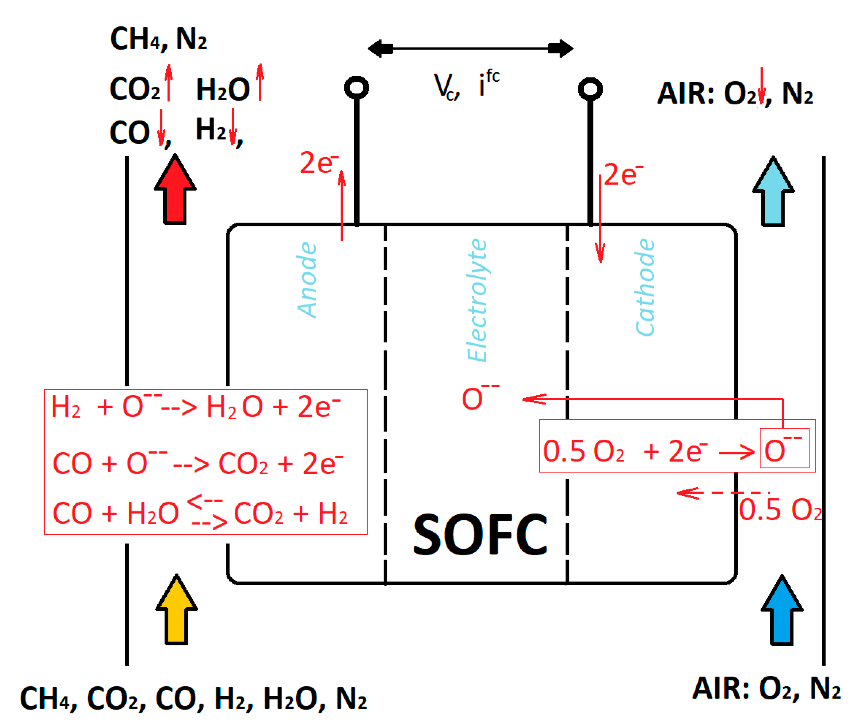
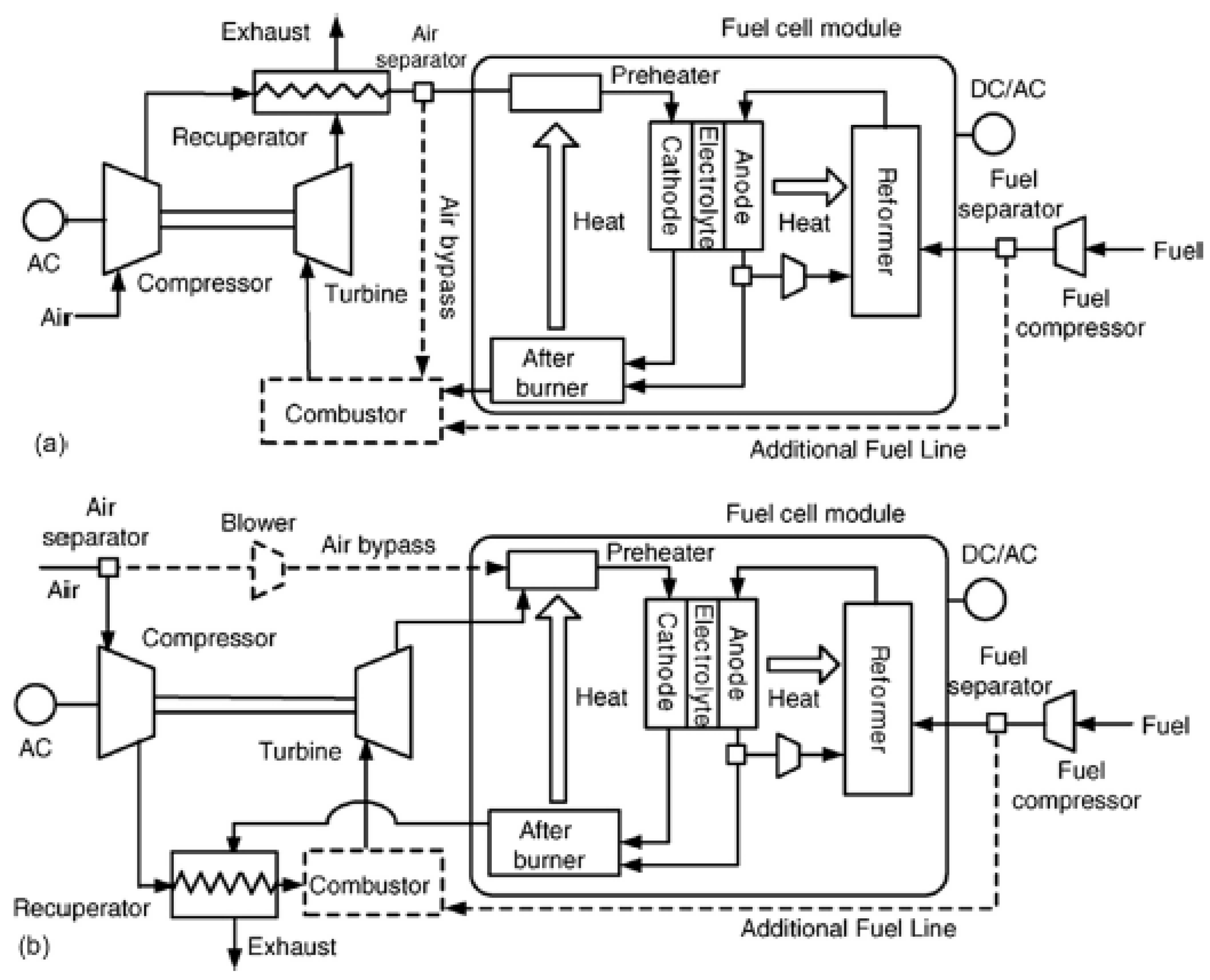
Figure 1. Thermo-electrochemical processes occurring in a SOFC core by feeding with a reformate or syngas stream.
Sustainability 14 15276 g001
Figure 2. Influence of the temperature on the thermo-electrochemical performance (constant anodic inlet flow rate).
Sustainability 14 15276 g002
Figure 3. Influence of the electrolyte thickness on the thermo-electrochemical performance (constant anodic inlet flow rate).
Sustainability 14 15276 g003
Figure 4. Influence of the pressure on the thermo-electrochemical performance (constant anodic inlet flow rate).
Sustainability 14 15276 g004
Figure 5. Influence of the anodic composition on the thermo-electrochemical performance (constant anodic inlet flow rate).
Sustainability 14 15276 g005
Figure 6. The thermo-electrochemical performance considering the anodic and cathodic inlet flow rate proportional to the electric current (constant Uf and Uo).
Sustainability 14 15276 g006
Figure 7. Plots of the fluid utilization factors regarding the cases assessed.
Sustainability 14 15276 g007
Figure 8. Typical anode supported tubular design SOFC, reprinted with permission from [71]. Copyright 2007 Elsevier B.V.
Sustainability 14 15276 g008
Figure 9. Scheme of the planar SOFC design.
Sustainability 14 15276 g009
Figure 10. Roll design.
Sustainability 14 15276 g010
Figure 11. Monolithic design: (a) co-flow, (b) cross-flow.
Sustainability 14 15276 g011
Figure 12. Cell modularity, series, and parallels.
Sustainability 14 15276 g012
Figure 13. Balance of plant of a SOFC power plant (the authors reserve the right to use the scheme in Figure 13 for a future paper). Power plant (a); SOFC core (b).
Sustainability 14 15276 g013
Figure 14. Molar concentration of the reforming output stream by converting pure methane as aa function of the steam to carbon ratio, temperature, and pressure.
Sustainability 14 15276 g014
Figure 15. Carbon deposition in the reactor by the Boudouard reaction, methane cracking, and the production of vapor as a function of the steam to carbon ratio, temperature, and pressure.
Sustainability 14 15276 g015
Figure 16. Test on the fuel feeding with H2S impurities (T: 850 °C, j: 1 A/cm2), reprinted with permission from [160]. Copyright 2009 Elsevier B.V.
Sustainability 14 15276 g016
Figure 17. Configuration diagram of the solid oxide fuel cell (SOFC) system, reprinted with permission from [258]. Copyright 2019 by the authors. Licensee MDPI, Basel, Switzerland. Open access article distributed under the terms and conditions of the Creative Commons Attribution (CC BY) license (http://creativecommons.org/licenses/by/4.0/).
Sustainability 14 15276 g017
Figure 18. Schematic representation of the four plant layouts with different anode off gas recirculation schemes and reforming options, reprinted with permission from [259]. Open access article under the CC BY-NC-ND license (http://creativecommons.org/licenses/by-nc-nd/4.0/).
Sustainability 14 15276 g018
Figure 19. Simplified BFD of the CH2P plant concept; SOFC-based distributed generation of H2 and electricity.
Sustainability 14 15276 g019
Figure 20. PFD of the CH2P prototype system, with permission from [259]. Open access article under the CC BY-NC-ND license (http://creativecommons.org/licenses/by-nc-nd/4.0/).
Sustainability 14 15276 g020
Figure 21. SOFC/GT cycle pressurized (a) and ambient (b) with internal reforming and anode recirculation, with permission from [276]. Copyright 2006 Elsevier B.V.
Sustainability 14 15276 g021
Figure 22. A typical SOFC/ST power system scheme, reprinted with permission from [284]. Copyright 2010 Elsevier Ltd.
Sustainability 14 15276 g022
Figure 23. Simplified system layout for the 220 kW Siemens-Westinghouse SOFC/GT prototype, reprinted with permission from [301]. Copyright 2000 Elsevier Science S.A.
Sustainability 14 15276 g023
Figure 24. Scheme of the power system AD/SOFC proposed in the work of Rayner et al., reprinted with permission from [334]. Crown Copyright 2016 Published by Elsevier Ltd.
Sustainability 14 15276 g024
Figure 25. Gasifier/SOFC/turbine power plant scheme, reprinted with permission from [342]. Copyright 2018 Elsevier Ltd.
Sustainability 14 15276 g025
Figure 26. SOFC system roadmap at the mid-term.
Sustainability 14 15276 g026
Table 1. The parameters and operation condition settings.
Case Values
Variable123
Temperature700 °C850 °C1000 °C
Layer (electrolyte)60 × 10−4 cm34 × 10−4 cm8 × 10−4 cm
Anode: 240 × 10−4 cm
Cathode: 40 × 10−4 cm
Pressure3 bar10 bar20 bar
Composition
Anodic:
CH4, CO2, CO, H2, H2O, N2
CH4CO2COH2H2ON2CH4CO2COH2H2ON2CH4CO2COH2H2ON2
0.05230.06720.05040.420.410100.04750.10650.06950.36570.410800.03470.15030.08230.31340.41920
Cathodic:
Air (N2, O2)
N2O2N2O2N2O2
0.790.210.790.210.790.21
Fluid utilizations and fluid supply(for Cases 1–3)
Uf, Uo: Variable with electric current (management method 1)
Anodic flow rate (constant): V ˙ a n , i n = ( 10 · C e l l   A r e a   ) [ mL · min 1 ]
Cathodic flow rate (constant): V ˙ c a t , i n = ( 10 · V ˙ a n , i n ) [ mL · min 1 ]
__________________
Uf, Uo: Fixed (management method 2);
Uf: 0.85
Uo: 0.25
Anodic flow rate (proportional to electric current): V ˙ a n , i n ( e l e c t r i c   c u r r e n t   ) [ mL · min 1 ]
Cathodic flow rate (proportional to electric current): V ˙ c a t , i n ( e l e c t r i c   c u r r e n t   ) [ mL · min 1 ]
Parameters
Cell area100 cm2
Cell materialsAnode: Ni–YSZ
Cathode: (LSM) La0.8Sr0.2MnO3
Electrolyte: (YSZ) ZrO2-Y2O3
For second SOFC management Composition 2 was used as the anodic feeding gas, layer 2 as the electrolyte thickness, temperature T: 1000 °C, pressure p: 3 bar.
Table 2. Influence on the performance.
Influence on Performance (+/−)
Temperature
(Increase)
Layer
(Decrease Thickness)
Pressure
(Increase)
Composition
++++++++Depending on the fuel processing
Method 1: Uf variableMethod 2: Uf constant
Partial LoadPartial Load
−−−+++
Table 3. A comparison of the tubular and planar designs.
PropertyTubularPlanar
Power densityLowHigh
Volumetric power densityLowHigh
High temperature sealingEasyDifficult
Start-up and shut-downFast Slow
Interconnector fabricationDifficultHigh cost
Production costHighLow
Thermal cycling stabilityHighLow
Table 4. SOFC companies worldwide and the main SOFC products.
CompanyCountryMain Product
(Characteristics)
FeedingWebsite
Atrex Energy USA100 W–4.5 kW
(SOFC tubular)
Propane and natural gashttp://www.atrexenergy.com/ (accessed on 12 July 2021)
Bloom Energy USA100–250 kW
(SOFC planar)
ηel: 50%
Natural gas and biogaswww.bloomenergy.com (accessed on 16 September 2022)
Convion Ltd. Finland50–300 kW
(SOFC planar)
ηel: 53–60%
Natural gas and biogashttp://convion.fi/ (accessed on 16 September 2022)
CoorstekUSAComponents for SOFC
(SOFC planar)
https://www.coorstek.com/english/materials/technical-ceramics/specialty/active-ceramic-membranes/ (accessed on 16 September 2022)
Delphi USAAPU SOFC
9 kW
ηel: 30–50%
Natural gas, diesel, bio-diesel, propane, gasoline, coal-derived fuelwww.delphi.com (accessed on 16 September 2022)
Fuel Cell EnergyCanada, USAHundreds kW–tens MW
ηel: 50%
Natural gaswww.fuelcellenergy.com (accessed on 16 September 2022)
h2e Power Systems Inc.India, USA250 W–10 kW
(kW—MW scale)
(CHP)
ηel: 50–60%
Natural gas, biogas (diesel optional with external reforming)http://h2epower.net (accessed on 16 September 2022)
LG Fuel Cell SystemsUK, USA, SingaporeSOFC/GT systems (250 kW)
(SOFC flat tubular)
ηel: 50–60%
Natural gashttps://www.hydrogen.energy.gov/pdfs/htac_apr13_6_fleiner.pdf (accessed on 16 September 2022)
Mitsubishi-Hitachi Heavy IndustriesJapanSOFC/GT systems (>200 kW–1 MW)
ηel: 52%
Methane basedhttps://www.mhi.com/products/energy/sofc.html (accessed on 16 September 2022)
mPower GmbHGermany1–10 kW → 50 kW
ηel: 50%
Multi fuelswww.mpowergmbh.de/ (accessed on 16 September 2022)
New enerday GmbHGermany500 W
ηel: 35%
Liquid fuelswww.new-enerday.com (accessed on 16 September 2022) *
SOLIDpower SpA ItalykW
(SOFC planar)
ηel: 60%
Gas, biogas, hydrogenhttps://solydera.com/ (accessed on 16 September 2022)
Sunfire-StaxeraGermany4.5 kW
ηel: 48%
Wide range gaseswww.sunfire.de (accessed on 16 September 2022)
POSCO EnergySouth Korea100–2.5 MWNatural gas, biogaswww.poscoenergy.com (accessed on 16 September 2022)
SOFCMAN Energy Technology Co., Ltd.China500 W–tens kW
ηel: 30–50%
Hydrogen, natural gas, biogas, propane, etc.www.sofcman.com (accessed on 16 September 2022)
ZegpowerNorway50 kW–tens MW
ηel: 50%
Purified landfill gas, biogas, gasified biomasswww.zegpower.no (accessed on 16 September 2022)
AdelainUK250 W–1 kW
(SOFC microtubular)
Hydrocarbon basedwww.adelan.co.uk (accessed on 16 September 2022)
Ceres PowerUKMicro-CHPNatural gaswww.cerespower.com/ (accessed on 16 September 2022)
ElcogenEstoniakW–hundreds kW
(SOFC planar, circular, rectangular)
Hydrocarbon basedwww.elcogen.com (accessed on 16 September 2022)
Haldor Topsøe ASDenmarkResidential micro-CHP www.topsoe.com (accessed on 16 September 2022)
Kerafol GmbHGermanySOFC components http://www.kerafol.com/en/sofc/ (accessed on 16 September 2022)
MiCoSouth KoreakW
Ceramics for
(SOFC planar, micro-tubular)
ηel > 50%
http://www.micopower.com/ (accessed on 16 September 2022)
Huatsing Jingkun New Energy Technology Co., Ltd.ChinakW
ηel: 50%
http://en.huatsing-power.com (accessed on 16 September 2022)
Chaozhou Three-Circle Co., Ltd.ChinaCeramics www.cctc.cc (accessed on 16 September 2022)
* Now acquired by sunfire-https://www.sunfire.de/en/ (accessed on 16 September 2022).
Publisher’s Note: MDPI stays neutral with regard to jurisdictional claims in published maps and institutional affiliations.

