Article

Seamless Power Management for a Distributed DC Microgrid with Minimum Communication Links under Transmission Time Delays

Department of Electrical and Information Engineering, Research Center for Electrical and Information Technology, Seoul National University of Science and Technology, 232 Gongneung-ro, Nowon-gu, Seoul 01811, Korea
*
Author to whom correspondence should be addressed.
Sustainability 2022, 14(22), 14739; https://doi.org/10.3390/su142214739
Submission received: 22 September 2022 / Revised: 3 November 2022 / Accepted: 5 November 2022 / Published: 9 November 2022
(This article belongs to the Special Issue Microgrid and Energy System Management)

Abstract

:
To maintain voltage stabilization under transmission time delays, this paper proposes a seamless power management scheme for a distributed DC microgrid (DCMG) with minimum digital communication links (DCLs). First, a DCL topology with minimum communication data is presented for the construction of distributed DCMG system not only to mitigate the communication burden but also to enhance the system’s flexibility and reliability. In addition, based on information gathered from nearby agents and local measurements, the operating modes of local agents in a DCMG system are determined properly to ensure a proper power balance under various conditions. During normal operation, the proposed scheme works as a distributed control scheme either in the grid-connected or islanded mode to take advantage of the distributed control method. To maintain seamless power management even under transmission time delays such as grid fault detection delays and grid recovery detection delays, the operating modes of each agent in a DCMG system are switched to a decentralized scheme based on the droop control method. When the utility grid information is properly identified by all power agents after a transmission time delay, the DCMG system returns to the distributed control scheme based on DC-link voltage (DCV) control to guarantee voltage stabilization. Furthermore, the scalability issue of a distributed DCMG system is also considered in this paper when an additional energy storage system (AESS) agent is involved in the DCMG system. For this purpose, a DCL topology with minimum communication data is designed for the AESS, which enables power units to participate in or to leave the distributed DCMG system easily. Simulation and experimental results under various conditions demonstrate the effectiveness and reliability of the proposed seamless power management strategy.

1. Introduction

Industrialization and modernization trends around the world have a significant impact on the increased level of global electricity demand. On the other hand, the limited supply of fossil fuels, such as petroleum, coal, and natural gas, used by conventional power generators is diminishing more every day. Moreover, the emissions produced by the use of fossil fuels have negative effects on the environment [1]. In this regard, microgrid systems which consist of a utility grid, an energy storage system (ESS), renewable energy sources (RESs), and loads, have received increased levels of attention from researchers [2].
Several RESs, such as photovoltaic (PV) and fuel cells, work as direct current (DC) sources [3]. In addition, the DC loads account for around 50% of overall building loads. Also, with the proliferation of electric vehicles (EVs), it can be expected that the demand for DC sources will increase rapidly in the near future [4].
Inspired by these concerns, the DC microgrid (DCMG) system has been the subject of much interest recently. In comparison to alternating current (AC) microgrids, DCMG not only eliminates the unnecessary AC–DC and DC–AC power conversion stage but also allows control issues such as the harmonics, frequency, and reactive power to be disregarded [5,6]. Furthermore, the complexity of controlling the DCMG system is significantly reduced compared to that of the AC microgrid.
From a communications perspective, DCMG control types can be classified into centralized control, distributed control, and decentralized control. Centralized control can be implemented by employing a centralized controller that connects to each power agent via digital communication links (DCLs) to manage the power in the DCMG system [7,8]. However, the centralized control method has many drawbacks related to system efficiency and flexibility. On the other hand, in decentralized control, each power unit independently maintains power to achieve a power balance by only using local measurements. This method is known to improve the flexibility and reliability of the DCMG system [9,10]. However, owing to the absence of DCLs, each power agent suffers from a lack of information on the global system, which leads to difficulty in achieving optimal power management in the DCMG system [11]. To overcome this weakness, distributed control is considered a replacement solution by combining the advantages as well as reducing the disadvantages of the above methods [12].
Generally, in distributed control, each power agent independently determines the operation and power flow based on information from nearby power units through DCLs [13]. Several DCMG systems using a distributed control method have been presented to ensure a proper system power balance under various conditions [14,15,16,17]. In study [14], a distributed control strategy for a multi-microgrid (MMG) system based on consensus control was proposed to achieve a power balance in a DCMG. A consensus algorithm is used to determine the operating modes of each agent with the information acquired from the neighboring agent. To optimize the power in real time and reduce the size of the transmitted data, a distributed control scheme was introduced for the DCMG structure [15]. To obtain the power allocation and voltage restoration in islanded DCMG system, a power management approach by combining the droop control and distributed secondary control schemes is presented in [16]. Also, this scheme introduces pinning gains in the distributed secondary control to improve the system’s scalability. Then, considering various energy-storage lifetimes and power costs, a study to obtain the optimal operation of a DCMG system under different scenarios was presented [17]. Although these control schemes in [13,14,15,16,17] achieve their main objectives, simplification of the DCMG communication structure using the minimum number of DCLs, as well as optimization of the DCMG system cost, requires further consideration.
Currently, considering the rapid development of EVs, which have been utilized to minimize not only global climate change but also economic consumption costs, the scalability issue of a DCMG system due to the involvement of additional energy storage agents has become another primary concern [18]. In study [19], a hybrid type of architecture with a minimum exchange data size was proposed for a DCMG when an ESS agent is added. Power management based on fuzzy logic control was presented to achieve the balanced battery state of charge (SOC) and voltage stabilization without transmission time delays by adjusting the droop coefficients [20]. In other works [21,22,23], different control methods were introduced to guarantee SOC balancing for multiple ESSs under transmission time delays in a DCMG system. However, the implementation of these schemes increases the number of communication links and communication burdens. In addition, the optimal communication topology issue was not specifically addressed in those studies [19,20,21,22,23].
DCLs, which are utilized to transmit data among power agents in a distributed DCMG system, may experience transmission time delays due to the distances among power agents, the size of the data, or the network protocol [24,25,26]. Transmission time delays hinder each power agent from coordinating optimally. Moreover, they have negative effects on the microgrid system, such as power imbalances and voltage oscillations [27,28]. Motivated by this concern, the researchers in [29] proposed a distributed secondary control to achieve voltage restoration and adjustable current sharing under uniform time delays. In the study [30], a novel distributed secondary method for DCMGs is presented under both fixed time delay and varying time delay. Specifically, the problem caused by transmission time delays is more critical during operational transitions of the microgrid system from the grid-connected mode to the islanded mode and vice versa. Normally, in the grid-connected mode, the utility grid maintains the power balance and regulates the voltage in the DCMG system. When a grid fault occurs, the utility grid agent transmits data to other agents through DCLs to provide information about the condition of the utility grid. Then, voltage stabilization and a proper power balance of the DCMG system are achieved by other power agents in the islanded mode. However, under a grid fault detection delay, the utility grid cannot transfer the exact grid condition at the proper moment to the other agents. Hence, the power balance in the DCMG system cannot be achieved because no power agents regulate the DC-link voltage (DCV). In contrast, a grid recovery detection delay implies a circumstance in which data received by other agents from the utility grid agent is delayed even when the utility grid recovers from the fault. Thus, the other power agents consider that the utility grid still has a fault. Then, there exists more than one power unit regulating the DCV at the same time, which causes the power-sharing in the DCMG to be unstable. To solve this problem, a distributed secondary control scheme was presented to achieve not only voltage restoration but also current sharing for the DCMG under bounded transmission time delays [29]. In another work [31], a power flow strategy for a distributed DCMG was designed to maintain the power balance in the presence of utility grid communication problems.
In this paper, seamless power management for a distributed DCMG with a minimum DCLs structure is proposed in an effort to enhance the voltage and power stabilization even under transmission time delays. As transmission time delays communication data, this paper considers both the grid fault detection delay and grid recovery detection delay conditions. During normal operation, the proposed scheme undertakes distributed control either in the grid-connected or islanded mode to use the advantages of the distributed control method. To achieve seamless power management as well as to ensure a power balance even under transmission time delays, the operating modes of each agent in a DCMG system are switched to the decentralized scheme based on the droop control method. Droop control determines the operations of the DCMG system based on the designed droop characteristic and local measurements of the DCV value. The control strategies of local power agents under transmission time delays are presented by the flow charts, which is a computationally efficient and simple way to implement them in a real embedded system. In addition, a simple communication topology is also introduced in this paper, not only to minimize the data size in an exchange packet but also to potentially optimize the DCMG system cost. To demonstrate its flexibility and scalability, the proposed scheme also presents a power management and minimum DCL topology when an additional ESS (AESS) agent is involved in an existing DCMG system. The validity of the proposed control strategy is verified by simulation and experimental results under a variety of scenarios. The main contributions of this paper are as follows:
(i)
A system communication topology for a distributed DCMG with minimum DCLs is proposed to achieve an optimal system cost. Because the proposed scheme relies on a limited exchange data size in a packet, general digital I/O port pins are sufficient to exchange the data between neighboring agents of a distributed DCMG system, which significantly simplifies the hardware architecture of the power agent.
(ii)
Seamless power management can be maintained even under transmission time delays, such as the grid fault detection delay and grid recovery detection delay conditions. In these situations, the DCMG system smoothly switches the operation to the decentralized scheme based on the droop control method to avoid miscoordination of each power unit, which may result in a system imbalance. When other power agents clearly detect the utility grid information precisely after a transmission time delay, the DCMG system changes the operation from decentralized control to distributed control to maintain the DCV at a nominal value.
(iii)
To enhance the scalability of the DCMG system, the proposed scheme presents a DCL topology with minimum communication data even when an AESS agent is present in an existing distributed DCMG system. The proposed scheme only requires two additional DCLs for AESS involvement, which enables power units to participate in or leave the distributed DCMG system easily.
This paper is organized as follows: Section 2 presents the system configuration and the proposed communication topology. Section 3 describes the power management and control strategy of each local agent under transmission time delays. Section 4 addresses the scalability issue of the proposed distributed DCMG due to the involvement of the AESS agent. Section 5 and Section 6 present the simulation and experimental results, respectively. Finally, Section 7 concludes the paper.

2. System Configuration of a Distributed DCMG

2.1. Configuration of DCMG

Figure 1 shows the configuration of the DCMG considered in this study, which is composed of four power agents: a battery agent, a load agent, a wind turbine agent, and a utility grid agent. The wind turbine agent only supplies power to a DC-link via a permanent magnet synchronous generator (PMSG) and a unidirectional AC/DC converter. The load agent only absorbs the power from the DC-link. When the supplied power is less than the demand power, the switches in the load agent are utilized to disconnect unnecessary DC loads. The utility grid agent and battery agent, which operate in a bidirectional manner, can supply power to the DC-link or absorb power from the DC-link by means of a bidirectional AC/DC converter and a bidirectional interleaved DC/DC converter, respectively.
Figure 1 also depicts the interconnections among power agents, showing the power lines, power flow, and DCLs to exchange information in a distributed control scheme. In Figure 1, P B , P L , P W , and P G denote the power flow of the battery, the load, the wind turbine, and the utility grid agents with the DC-link, respectively. To represent the power relationship in this paper clearly, it is defined that these variables have negative values when the power agents supply power into the DC-link. In contrast, they have positive values when the power agents absorb power from the DC-link. The DCLs are used to exchange information between nearby power agents. In this paper, power management is simply achieved using the minimum number of DCLs and the minimum data size. The operating modes of each agent can be determined by collecting data from neighboring agents and their corresponding local sensor measurements.

2.2. System Communication Topology

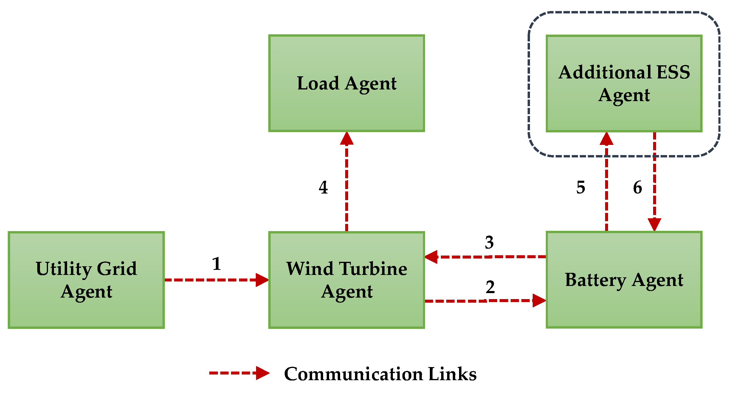
Figure 2 describes the system communication topology considered in this paper for distributed DCMG control. For the given DCMG system shown in Figure 1, which consists of four power agents, only four DCLs are sufficient to achieve a proper power balance as well as to optimize the system cost. Each DCL contains information to assist the receiver agent in determining the appropriate control mode. Table 1 presents detailed descriptions of the DCLs shown in Figure 2, specifically the exchange data variables, data type, and data information of each communication link. All communication data is in a binary data format, which minimizes communication efforts. The first communication link is assigned to transfer the data from the utility grid agent to the wind turbine agent ( D G W ). With this communication link, the utility grid agent sends to the wind turbine agent information on whether the utility grid agent regulates the DCV. The wind turbine agent transmits to the battery agent via the second communication link the information D W B as to whether the utility grid or wind turbine agent regulates the DCV. In contrast, the third communication link is utilized to transfer data from the battery agent to the wind turbine agent D B W , which indicates whether the DCV is controlled by the battery agent. The operating modes of the load agent can be determined clearly by gathering information from the wind turbine agent D W L , through the fourth communication link.
As mentioned earlier, if a DCMG system is expanded due to the involvement of an AESS agent, fifth and sixth communication links become necessary to exchange data between the battery agent and the AESS agent. The scalability issue of a DCMG system will be explained in detail in Section 4.

3. Power Management and Control Strategy of Local Agents under Transmission Time Delays

3.1. Control Strategy of the Utility Grid Agent

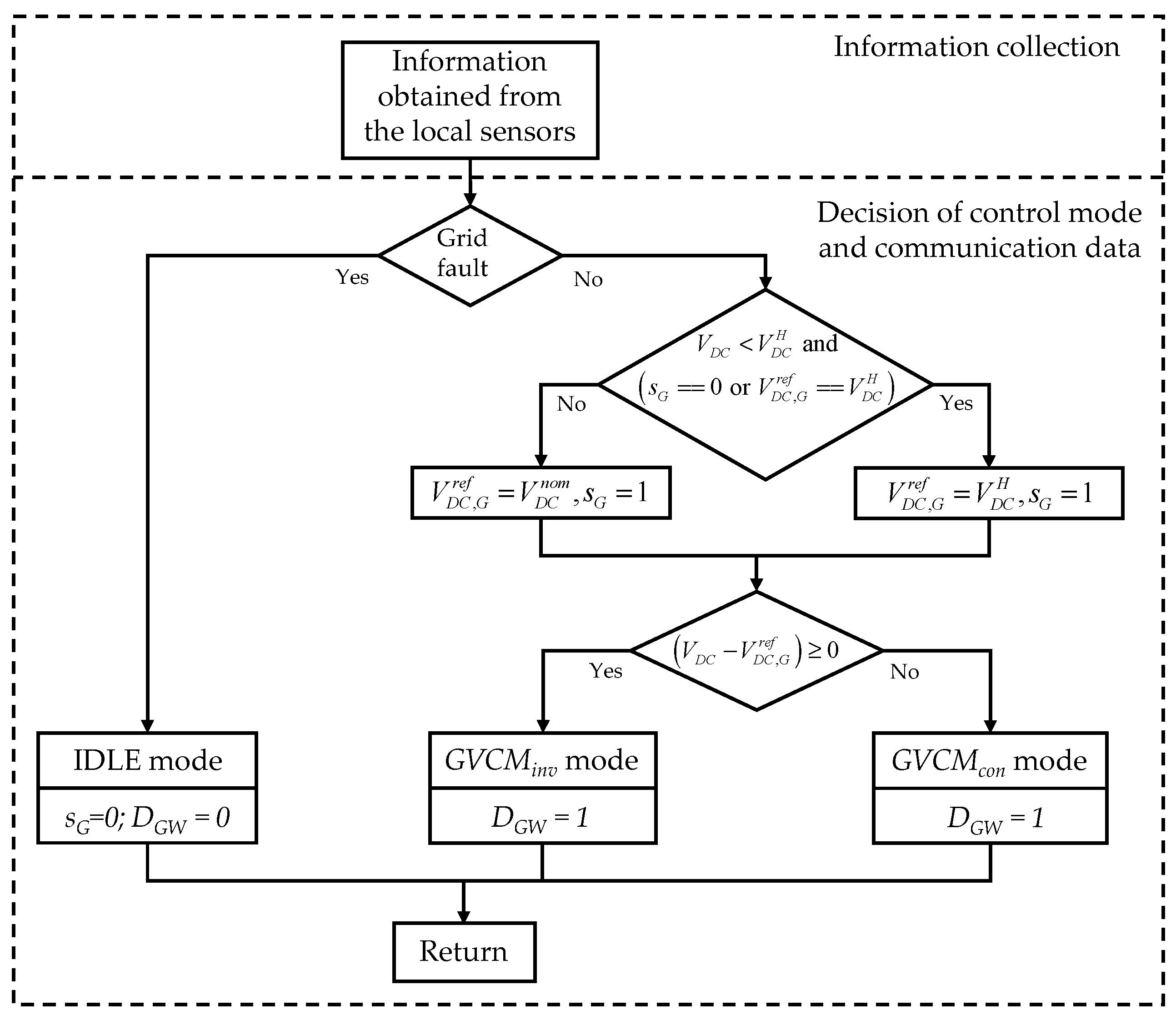
Figure 3 shows the control strategy of the utility grid agent in the proposed distributed DCMG system. In this figure, s G denotes the state of the utility grid agent, V D C is the measured DCV, V D C H is the highest DCV level, V D C , G r e f is the DC-link reference voltage of the utility grid agent, and V D C n o m is the nominal DCV. Instead of sharing the information with all agents in the DCMG, the utility grid agent only transfers data to the wind turbine agent to achieve power management with a minimum number of communication links and an optimized system cost. When a grid fault occurs, the utility grid agent cannot regulate the DCV. In this case, the information D G W , which is set to zero, is transmitted to the wind turbine agent. The state s G is used to represent the operation of the utility grid agent in the distributed DCMG system. When the state s G equals zero, it indicates that the distributed DCMG operates in the islanded mode. In contrast, if s G is set to one, the distributed DCMG operates in the grid-connected mode.
When the utility grid recovers from the grid fault, the grid recovery control strategy proposed in this study serves to avoid a situation in which two power agents regulate the DCV at the same time due to a grid recovery detection delay. In the islanded mode, the state of the utility grid agent sG equals zero and the DCV is controlled at V D C n o m either by the battery or the wind turbine agent.
In case of a grid recovery, to prevent the condition in which two power agents regulate the DCV at the same time under a grid recovery detection delay, the utility grid agent sets V D C , G r e f as V D C H , which is higher than the nominal voltage level, as shown in Figure 3. Moreover, the state of the utility grid agent s G is set to one. As a result, the battery or wind turbine agent stops regulating the DCV. Then, if V D C is higher than V D C , G r e f , the utility grid agent undertakes DCV control via the inverter mode ( G V C M i n v ). In contrast, if V D C is lower than V D C , G r e f , the utility grid agent undertakes DCV control in the converter mode ( G V C M c o n ). Both G V C M i n v and G V C M c o n modes use a proportional-integral (PI) controller for voltage regulation. Because the utility grid agent regulates the DCV, the communication data from the utility grid agent to the wind turbine agent, D G W , is set to one.
As soon as V D C reaches V D C H , the DC-link reference voltage of the utility grid agent V D C , G r e f is changed from the highest DCV level V D C H to the nominal DCV level V D C n o m to ensure voltage stabilization even under a transmission time delay of the grid recovery. According to the errors of the V D C and V D C , G r e f , the operating modes of the utility grid agent are determined autonomously as the G V C M i n v or G V C M c o n mode. The local tracking control of the utility grid agent is implemented by using the cascaded loops of an outer-loop voltage control and inner-loop current control with the PI controllers to ensure zero steady-state tracking errors [32].

3.2. Control Strategy of the Wind Turbine Agent

Figure 4 shows the control strategy of the wind turbine agent in the proposed distributed DCMG system. In this proposed distributed DCMG system, the wind turbine agent transmits binary data D W B and D W L to the battery and load agents, respectively. On the other hand, it receives binary data D G W and D B W from the utility grid and battery agents, respectively. In addition, the wind turbine agent uses the internal state variables s W and the DCV state ( V D C C o n ). According to the state value s W , the wind turbine agent operation is determined as follows:
  • Distributed scheme in grid-connected or islanded mode—when s W = 1;
  • Decentralized scheme in islanded mode—when s W = 2;
  • Decentralized scheme in grid-connected mode—when s W = 3.
The DCV state variable ( V D C C o n ) provides information about the DCV level. When V D C is in the region between the lowest DCV level ( V D C L ) and V D C H , the DCV state V D C C o n is set to one. Otherwise, V D C C o n is set to zero. In Figure 4, V D C , e r r o r is defined as V D C V D C n o m . When the DCMG works in the distributed islanded mode without transmission time delays, the data D G W is set to zero and s W is set to one, which indicates that the utility grid agent does not regulate the DCV and that the DCMG operates in the distributed mode. In this case, if V D C , e r r o r is higher zero and D B W = 0 (indicating that the battery agent does not regulate the DCV), the DCV is regulated in the DCV control mode by the wind turbine agent (VCM). In the VCM mode, the PI controller is utilized to regulate the DCV at V D C n o m . In this situation, the communication data D W B is set to one while the communication data D W L is set to zero. Suppose either the battery agent regulates the DCV ( D B W = 1 ) or V D C , e r r o r is less than zero, the wind turbine agent operates in the maximum power point tracking mode (MPPT) and D W B is set to zero while D W L equals one.
When the DCMG operates in the grid-connected mode without transmission time delays, the utility grid agent regulates the DCV ( D G W = 1 ), the wind turbine agent operates in the MPPT mode with D W B set to one, and D W L is set to zero.
Even in the case of transmission time delays related to grid fault detection and grid recovery detection, the feasibility of the proposed seamless power management scheme for a distributed DCMG is ensured by determining the operating modes of the wind turbine agent.
As the grid recovers from a fault, the utility grid agent returns to the regulation of the DCV at V D C H . However, for a grid recovery detection delay, the transmitted data D G W still equals zero. As V D C reaches the V D C H level, V D C C o n is set to zero, which causes the wind turbine agent to change its operation from the distributed islanded mode to the decentralized droop control mode. In this situation, s W is set to two and D W B and D W L do not change, as shown in Figure 4. The droop control mode will be explained in Section 3.5. When the wind turbine agent receives the grid recovery information as a result of D G W switching to one, which indicates that the utility grid returns to the grid-connected mode through regulation of the DCV at V D C n o m , the wind turbine agent operates in MPPT mode, and s W and D W B are set to one.
In the event of a grid fault detection delay, the communication data D G W set to one is transmitted to the wind turbine agent even if the utility grid agent is disconnected from the DCMG due to a fault. As a result, the DCV either rises rapidly due to the redundant power or falls quickly due to insufficient power, which causes V D C C o n to be set to zero because the DCV value escapes the region between V D C L and V D C H . In this situation, the wind turbine agent operates in the droop control mode to maintain the power balance, as shown in Figure 4. Even if the utility grid is disconnected from the DCMG, all agents recognize that the DCMG system operates in the decentralized grid-connected mode due to the communication time delay. As a result, s W is set to three while D W B and D W L do not change. Once the grid fault is identified by the wind turbine agent after the transmission time delays with the communication data D G W , the wind turbine agent operates with VCM or MPPT in the islanded mode depending on D B W and V D C , e r r o r , respectively. The local tracking control of the wind turbine agent is similarly realized with the cascaded control loops with the PI controls [9].

3.3. Control Strategy of the Battery Agent

Figure 5 shows the control strategy of the battery agent in the proposed distributed DCMG system. In the proposed system, the battery agent transmits two binary data D B W and D B A to the wind turbine and the AESS agents, respectively. In addition, the battery agent likewise receives two binary data D W B and D A B from the wind turbine and AESS agents, as shown in Figure 2. The control strategy of the battery agent due to the additional ESS involvement will be explained in Section 4.1. In Figure 5, S O C B denotes the battery SOC, S O C B , m i n and S O C B , m a x are correspondingly the minimum and maximum battery SOC, P B , c h a r m a x is the maximum battery charging power, and s B is the internal state variable of the battery agent. To minimize DCLs in this study, the battery agent does not exchange data directly with the utility grid agent. The operation of the battery agent is determined based on the internal state s B and communication data D W B , as follows:
  • Distributed scheme in grid-connected or islanded mode—when s B = 1;
  • Decentralized scheme in islanded mode—when s B = 2, D W B = 0;
  • Decentralized scheme in grid-connected or islanded mode—when s B = 3, D W B = 1.
When the DCMG works in the distributed islanded mode without transmission time delays, the data D W B is set to zero and s B is set to one, which indicates that the utility grid and wind turbine agents do not regulate the DCV and that the DCMG operates in the distributed mode. In this case, if V D C , e r r o r is lower than zero and S O C B is higher than S O C B , m i n , the battery agent undertakes DCV control in the battery discharging mode ( B V C M d i s ). In this situation, the communication data D B W is set to one. When V D C , e r r o r is higher than zero, S O C B is in the region between S O C B , m i n and S O C B , m a x , and P B is less than P B , c h a r m a x , the battery agent undertakes DCV control in the battery charging ( B V C M c h a r ) mode and D B W is also set to one. Both B V C M d i s and B V C M c h a r modes use a PI controller to regulate the DCV at V D C n o m . In contrast, if P B reaches P B , c h a r m a x , the battery agent undertakes constant current control in the battery charging ( B C C M c h a r ) mode. In this case, D B W is set to zero, which indicates that the battery agent does not regulate the DCV. In the B C C M c h a r mode, a PI controller is utilized to regulate the battery current at the maximum battery charging current. Once the S O C B value escapes the region between S O C B , m i n and S O C B , m a x , the battery agent operates in the IDLE mode and D B W is set to zero.
When the utility grid or wind turbine agent regulates the DCV without transmission time delays ( D W B = 1 ) and S O C B is less than S O C B , m a x , the battery agent operates in the B C C M c h a r mode. However, as S O C B reaches S O C B , m a x , the battery agent operates in the IDLE mode. In both situations, the battery agent does not regulate the DCV and D B W is set to zero, as shown in Figure 5.
Although the battery agent does not receive the utility grid information directly in the case of transmission time delays of grid fault detection and grid recovery detection, DCV stabilization is still guaranteed in the proposed scheme by determining the operating modes of the battery agent.
It is assumed that the battery agent regulates the DCV at V D C n o m in the islanded mode when the grid recovers from a fault. In this situation, the utility grid agent returns to the regulation of the DCV at V D C H . However, the transmitted data D W B still equals zero due to the grid recovery detection delay. As soon as V D C reaches the V D C H level, V D C C o n is set to zero, which causes the battery agent to change its operation from the distributed islanded mode to the decentralized droop control mode. As a result, the state s B is set to two without a change of D B W , as shown in Figure 5. When the grid recovery information is transferred to the wind turbine agent ( D G W switches to one), this is also transmitted to the battery agent by the data D W B , which indicates that the utility grid returns to the grid-connected mode by regulating the DCV at V D C n o m . As a result, the battery agent changes its operation to the B C C M c h a r or IDLE mode depending on the S O C B , s B is set to one, and D B W is set to zero.
If the wind turbine agent regulates the DCV at V D C n o m in the islanded mode ( D W B = 1) at the instant of grid recovery from a fault, the utility grid agent returns to the regulation of the DCV at V D C H . Similarly, the battery agent changes its operation from the distributed islanded mode to the decentralized droop control mode as soon as V D C C o n switches to zero. In this situation, s B is set to three while D B W does not change. Once the DCV returns to the V D C n o m value, the battery agent operation switches to the distributed grid-connected mode, s B is set to one, and D B W is set to zero.
In the event of a grid fault detection delay, the communication data D W B set to one is transmitted to the battery agent even if the utility grid agent is disconnected from the DCMG due to a fault. If the wind turbine agent supplies power exceeding the sum of the demand load and the maximum battery charging, the DCV rises rapidly. As the DCV reaches V D C H , V D C C o n switches to zero, which causes the battery agent to operate in the droop control mode to ensure voltage stabilization, as shown in Figure 5. As a result, D B W does not change, and s B is set to three. Even if the utility grid is disconnected from the DCMG, all agents recognize that the DCMG system operates in the decentralized grid-connected mode owing to the communication time delay. As noted earlier, when the wind turbine agent receives the grid fault information, D G W is set to zero, and the wind turbine agent operation switches to the distributed islanded mode. In this situation, because the generated power of the wind turbine agent exceeds the sum power of the demand load and the maximum battery charging, V D C , e r r o r increases. As a result, the wind turbine agent regulates the DCV at V D C n o m in the VCM mode, the communication data D W B is set to one, and the battery agent switches to operate in the B C C M c h a r or IDLE mode in the distributed islanded mode.
In contrast, if the wind turbine agent supplies power less than the sum of the demand load and the maximum battery charging, V D C drops rapidly. As soon as the DCV decreases to the V D C L level, V D C C o n also switches to zero. Similar to the previous condition, the battery agent switches its operation to the decentralized droop control in the grid-connected mode, s B is set to three, and D B W does not change. When the grid fault information is transferred to the wind turbine agent, D G W is set to zero. Because the wind turbine agent does not have enough power to regulate the DCV, D W B is set to zero. Then, the battery agent regulates the DCV at V D C n o m in the distributed control mode. The local tracking control of the battery agent is implemented with the voltage control and current control [32].

3.4. Load Agent

Figure 6 shows the control strategy of the load agent in the proposed distributed DCMG system. In the proposed system, the load agent only receives binary data D W L from the wind turbine agent, as shown in Figure 2. In Figure 6, V D C p r e is the measured DCV in the previous time step, V D C L i m i t is the limited DCV level, and i and n denote the number of operating loads and all loads in the DCMG, respectively.
When the DCV value is lower than V D C L i m i t in the islanded mode, the load shedding mode is activated to protect the DCMG system from a critical condition. Otherwise, the load agent operates in the normal mode. In load shedding mode without the transmission time delays, the DCV is less than V D C L , which causes both the wind turbine and battery agents to switch to the droop control mode with s W and s B set to two. If the DCV exceeds V D C L as a result of load shedding, the s W and s B   states are again set to one. Then, both the wind turbine and battery agents return to their operations in the distributed islanded mode.
When the utility grid or wind turbine agent regulates the DCV ( D W L = 1 ) without a transmission time delay, the load agent operates in the normal mode if the number of operating loads i equals the number of total loads n . In contrast, the load agent operates in the load reconnecting mode if i is smaller than n .
If there exists the grid fault detection delay in the DCL, the data D W L set to one is transmitted to the load agent temporarily when the utility grid agent is disconnected from the DCMG due to a fault. In this case, if the power in the DCMG by the power sources is lower than the demand load, the DCV falls rapidly due to an insufficient power condition. To avoid this critical circumstance, the proposed scheme uses two protection methods. First, as explained in Section 3.2 and Section 3.3, the wind turbine and battery agents switch to the droop control mode when the DCV value is lower than V D C L . In addition, if the DCV decreases further to   V D C L i m i t , the load shedding mode is activated in the load agent.

3.5. Droop Control for Wind Turbine and Battery Agents under Transmission Time Delays

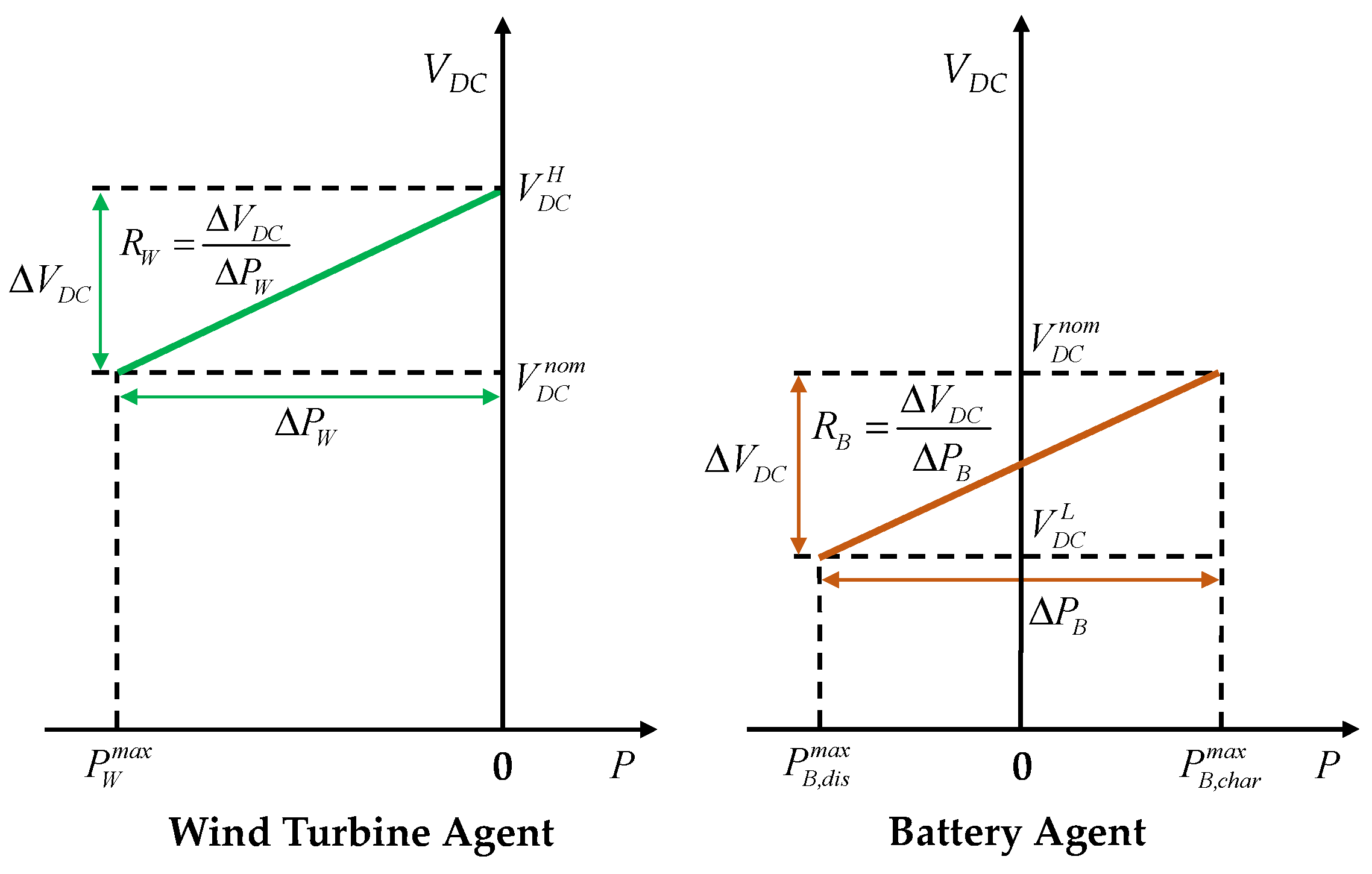
Droop control schemes are employed for wind turbine and battery agents in the proposed scheme when there are transmission time delays in the DCLs. Figure 7 shows the V-P droop curves for the wind turbine and battery agents in this case. In this figure, P W m a x denotes the maximum generation power of the wind turbine agent, P B , d i s m a x is the maximum battery discharging power, and R W and R B are the droop characteristics of the wind turbine and battery agents, respectively. According to the DCV level, the operation of droop control can be explained as follows:
  • For V D C n o m < V D C < V D C H : During this voltage interval, the wind turbine agent regulates the DCV via the voltage droop control mode (VDCM). In the V-P droop control scheme shown in Figure 7, R W can be obtained via Δ P W = 0 P W m a x and Δ V D C = V D C H V D C n o m . In this case, the battery agent operates in the BCCMchar mode for maximum charging.
  • For V D C L < V D C < V D C n o m : During this voltage interval, the battery agent regulates the DCV via the voltage droop control mode (BVDM). With Δ P B = P B , c h a r m a x P B , d i s m a x and Δ V D C = V D C n o m V D C L , R B can be obtained as shown in Figure 7. The wind turbine agent operates in the MPPT mode to supply the maximum level of power.

4. Scalability of the Proposed Distributed DCMG System

One of the desirable features of the DCMG system is that it enables various power sources to be integrated into the existing DCMG system simply and easily because it is much easier to construct a scalable DCMG system. To address this issue, the scalability of the proposed distributed DCMG system is discussed in this section.

4.1. Control Strategy of the Battery Agent in the Event of AESS Agent Involvement

Figure 8 shows the control strategy of the battery agent when an AESS agent is introduced into the existing DCMG system, as shown in Figure 2. When an AESS agent is involved, the battery agent gathers information about the AESS and transmits it to the other power agents. In this case, the communication data D B W   should be modified as follows:
0: Battery and AESS agents do not regulate DCV.
1: Battery/AESS agent regulates DCV.
The majority of the battery agent control algorithm is similar to Figure 5, even if an AESS agent is involved in the DCMG system as a power source. In this figure, the battery agent has different control schemes from those shown in Figure 8 when the utility grid and wind turbine agent cannot regulate the DCV.
If D W B = 0 without transmission time delays, S O C B > S O C B , m i n , V D C , e r r o r 0 , and P B is less than the maximum battery discharging power ( P B , c h a r m a x ), the battery agent undertakes constant current control in the battery discharging mode ( B C C M d i s ), D B A equals zero, and D B W is set to the same value as D A B . This indicates that if the AESS can regulate the DCV, this data is initially transmitted to the battery agent, after which it is also transmitted to the wind turbine agent.
If S O C B S O C B , m i n with D W B = 0 , the battery agent operates in the IDLE mode and D B A is set to zero. The value of D B W , which indicates whether the battery/AESS agent regulates the DCV, depends on D A B as determined by the AESS agent. If D A B is set to one, D B W also equals one, and vice versa.

4.2. Control Strategy of an AESS Agent

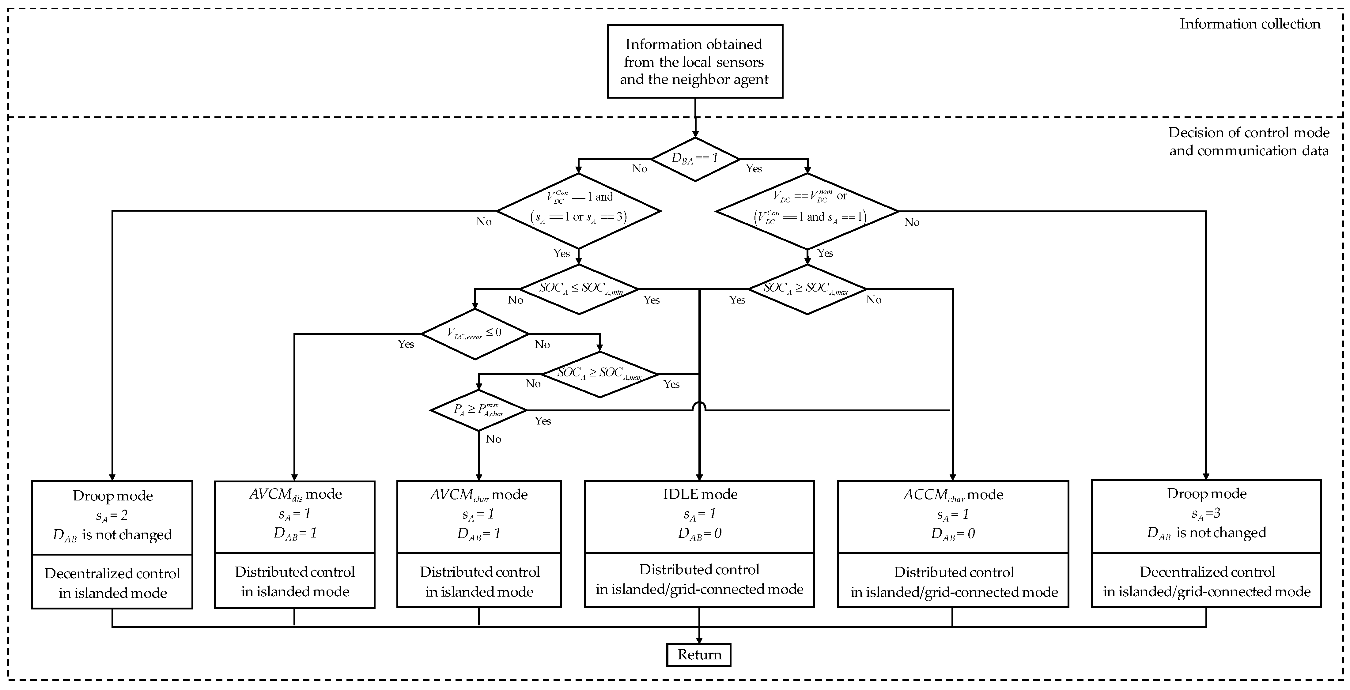
Figure 9 shows the control strategy of the AESS agent, which is identical to the control algorithm of the battery agent shown in Figure 5, with the only exceptions being the variables for the state and data, and the operating modes. In this figure, s A is the state of the AESS agent, S O C A ,   S O C A , m i n , and S O C A , m a x are the AESS SOC, minimum SOC, and maximum SOC, respectively; P A is the power flow between the AESS and the DC-link; and P A , c h a r m a x is the maximum AESS charging power. The operating modes of the AESS agent include DCV control in the AESS discharging ( A V C M d i s ) mode, DCV control in the AESS charging ( A V C M c h a r ) mode, and constant current control in the AESS charging ( A C C M c h a r ) mode.
Similarly, droop control schemes are also employed for the wind turbine, battery, and AESS agents under transmission time delays in the DCLs. Figure 10 shows the V-P droop curves in the event of AESS agent involvement. In this figure, P A , d i s m a x denotes the maximum AESS discharging power and V D C , B L is the low DCV level of the battery agent. According to the DCV level, the operation of the droop control scheme can be explained as follows:
  • For V D C n o m < V D C < V D C H : As mentioned earlier, the wind turbine agent regulates the DCV via VDCM with droop characteristic R W . In this case, the battery and AESS agents operate in the B C C M c h a r and A C C M c h a r modes for maximum charging.
  • For V D C , B L < V D C < V D C n o m : During this voltage interval, the battery agent regulates the DCV by BVDM with droop characteristic R B . With Δ P B = P B , c h a r m a x P B , d i s m a x and Δ V D C = V D C n o m V D C , B L , R B can be obtained, as shown in Figure 10. The wind turbine agent operates in the MPPT mode and the AESS operates in the A C C M c h a r mode.
  • For V D C L < V D C < V D C , B L : During this voltage interval, the AESS agent regulates the DCV via the voltage droop control mode (AVDM) with droop characteristic R A , which can be obtained as in Figure 10 with Δ P A = P A , c h a r m a x P A , d i s m a x and Δ V D C = V D C , B L V D C L . The battery and wind turbine agents operate in the B C C M d i s and MPPT mode, respectively, to supply the maximum level of power.

5. Simulation Results

In this section, the simulations are conducted for a distributed DCMG to verify the feasibility and reliability of the proposed control scheme based on the PSIM software. Simulation results are presented in the case of grid-connected mode, islanded mode, and transmission time delays with the system parameters listed in Table 2. As this study aims to construct a low-voltage DCMG, the nominal DCV is selected as 400 V, which enables easy connection to a 3-phase grid through a Y-Δ transformer. Other voltage levels are determined by considering the demand load power based on the studies in [9,31]. As transmission time delays, a time range of 0.5 to 1.0 s is used as in [27,33].

5.1. Transition from Grid-Connected to Islanded Mode without Grid Fault Detection Delay

Figure 11 shows the simulation results for the transition from the grid-connected to the islanded mode without the transmission time delays of the grid fault. In this figure, the DCV is controlled by the different agents to maintain a power balance under variations of wind power.
It is assumed that the DCMG system starts at t = 0.05 s in the grid-connected mode and S O C B is in the region between S O C B , m i n   and S O C B , m a x . Because the wind turbine agent supplies power lower than the sum of the demand load and the maximum battery charging, the utility grid agent regulates DCV at V D C n o m via G V C M c o n mode. In this situation, the wind turbine and battery agents operate in the MPPT and B C C M c h a r modes, respectively. Once the wind turbine agent injects power more than the sum of the demand load and maximum battery charging power at t = 0.3 s, the utility grid agent changes the operating mode from G V C M c o n to G V C M i n v mode to absorb the power from the DC-link.
As the grid fault occurs without transmission time delays at t = 0.5 s, the distributed DCMG system operation is switched to the islanded mode. In this case, depending on V D C , e r r o r and communication data D G W , D B W , and D W B as mentioned in Section 3.2 and Section 3.3, the wind turbine agent changes the operation from the MPPT mode to VCM mode to regulate DCV, and the battery agent keeps the B C C M c h a r mode. If the wind power suddenly falls at t = 0.8 s, the wind turbine agent does not have enough power to regulate the DCV. As a result, the battery agent operation switches from B C C M c h a r to B V C M c h a r mode to maintain the voltage stabilization at V D C n o m . The wind turbine returns to operate in MPPT mode. The result in Figure 11 clearly demonstrates that the power balance and voltage regulation are achieved for the proposed distributed DCMG system with minimum communication links. As compared to the study in [31], which produces a similar performance, the system structure becomes very simple, and the system cost is significantly reduced in the proposed scheme.

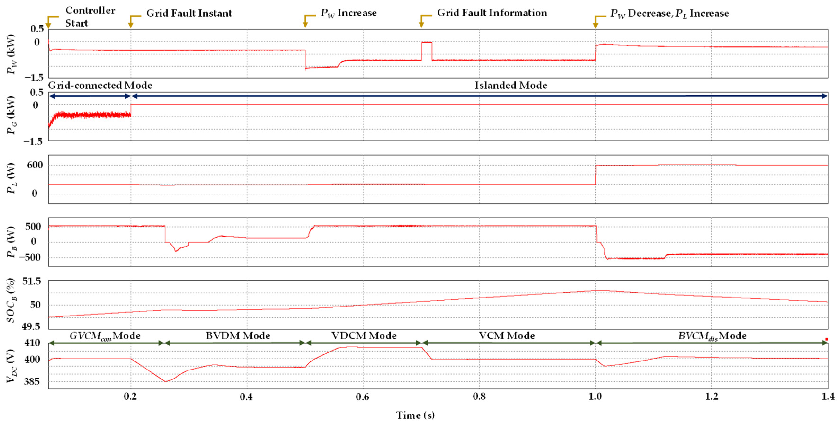
5.2. Case of Grid Fault Detection Delay

To verify the seamless power management of the proposed scheme, Figure 12 shows the simulation results under transmission time delays of grid fault detection. Similarly, all the agents start the control operation at t = 0.05 s in the grid-connected mode, S O C B is in the region between S O C B , m i n   and S O C B , m a x , and only load 1 is connected to the DC-link. The DCV is controlled at V D C n o m by utility grid agent in G V C M c o n mode, and the wind turbine and battery agents operate in the MPPT and B C C M c h a r modes, respectively.
At t = 0.2 s, the grid fault occurs. However, all the power agents recognize that the DCMG system operates in the distributed grid-connected mode because of communication time delays. As a result, V D C falls fast because the generated wind power is less than the sum of the demand load and maximum battery charging powers. When V D C decreases to V D C L , both the wind turbine and battery agents switch to the droop control mode. According to V-P droop curves in Figure 7 and V D C value, the battery agent changes from B C C M c h a r to BVDM mode to regulate DCV while the wind turbine agent keeps MPPT mode. Once the generated wind power rises rapidly at t = 0.5 s, the wind turbine agent changes the operation from MPPT to VDCM mode to ensure DCV stabilization. In this case, the battery agent switches to B C C M c h a r mode.
As soon as the grid fault information is properly transferred to the wind turbine agent at t = 0.7 s, the wind turbine agent changes the operation from VDCM to VCM mode to regulate DCV at V D C n o m while the battery agent operation is B C C M c h a r mode in the distributed islanded mode.
At t = 1.0 s, the wind power suddenly falls while the load agent needs to absorb more power from the DC-link. Then, the battery agent switches from B C C M c h a r to B V C M d i s mode to ensure the power balance. In this case, the wind turbine operation is switched to MPPT mode.

5.3. Case of Grid Recovery Detection Delay

To emphasize the uninterruptable power management of the proposed scheme, Figure 13 shows the simulation results in case of grid recovery detection delay when the battery agent regulates DCV. The DCMG system starts in the islanded mode with S O C B in the region between S O C B , m i n   and S O C B , m a x . Because the wind turbine agent does not have sufficient power to regulate the DCV, the battery agent regulates V D C at V D C n o m via B V C M c h a r Mode, and the wind turbine agent is in MPPT mode.
At t = 0.3 s, the utility grid is recovered from the fault, and the utility grid agent returns to regulate the DCV at V D C H . However, in case of the grid recovery detection delay, the transmitted data D G W still equals zero. As V D C reaches V D C H level, the wind turbine and battery agents switch the operation to the droop control mode. According to V-P droop curves in Figure 7, the wind turbine and battery agents operate in MPPT and B C C M c h a r modes, respectively. After that, the DCV is controlled by the utility grid agent to V D C n o m , which causes the battery agent operation to return to B C C M c h a r in the distributed grid-connected mode. When the wind power increases at t = 0.5 s, the utility grid agent also reduces the power supplied to the DC-link to maintain the power balance under transmission time delays.
When S O C B reaches to S O C B , m a x at t = 0.65 s, the battery agent operates in IDLE mode. Then, the wind power agent uses more power to supply the load, and the utility grid agent changes the operation from G V C M c o n to G V C M i n v mode to regulate DCV. As soon as the wind turbine agent receives the grid recovery information at t = 0.8 s, the wind turbine agent operation is returned to MPPT in the distributed grid-connected mode.

5.4. Case of AESS Agent Involvement

In this section, to demonstrate the flexibility of the proposed distributed DCMG system, an AESS agent is introduced in the existing DCMG system in Figure 1. Figure 14 presents the simulation results in the load-shedding mode when the AESS agent regulates DCV in the islanded mode. It is assumed that there are three loads in the DCMG structure, in which each load absorbs 500 W and has a priority in the order of load 1, load 2, and load 3.
Initially, the DCMG starts in the islanded mode, and both S O C B and S O C A are in the regions between the minimum and maximum, respectively. Because the sum of the wind turbine and maximum battery discharging power is lower than the demand load, the DCV is controlled to V D C n o m by AESS agent in A V C M d i s mode. The wind turbine agent operates in the MPPT mode while the battery agent runs the B C C M d i s mode, as shown in Figure 8.
At t = 0.2 s, the wind power suddenly falls, which causes the power in DCMG to be lower than the demand load. As a result, the DCV drops significantly to V D C L i m i t , and the load shedding mode is activated to avoid the power imbalance. After that, the AESS agent continues regulating DCV at V D C n o m , while the wind turbine and battery agents still operate in MPPT and B C C M d i s modes, respectively.
Once the utility grid agent recovers without the transmission time delays at t = 1.0 s, first, the DCV is controlled at V D C H by G V C M c o n as shown in Figure 3, with the state of the utility grid agent s G set to one. As a result, load 3 is reconnected to a DCMG system while the wind turbine, battery, and AESS agents temporarily switch to the droop control mode as soon as the DCV reaches to V D C H . After that, the DC-link reference voltage of the utility grid agent V D C , G r e f is changed from V D C H to V D C n o m , and the wind turbine, battery, and AESS agents operate in the MPPT, B C C M c h a r , and A C C M c h a r modes, respectively, in the distributed grid-connected mode.
To emphasize the reliability of the proposed control scheme under a more critical case, Figure 14b shows the simulation results in load shedding under grid fault detection delay with a transmission time delay of 0.2 s. It is assumed that the DCMG control starts in the grid-connected mode with S O C B in the maximum, and S O C A in the region between S O C A , m i n and S O C A , m a x . The utility grid agent regulates DCV at V D C n o m via G V C M c o n mode. The wind turbine, battery, and AESS agents operate in MPPT, IDLE, and A C C M c h a r modes, respectively.
At t = 0.2 s, the grid fault occurs. However, all the agents recognize that the DCMG system operates in the distributed grid-connected mode because of communication time delays. As soon as V D C falls to V D C L , the wind turbine, battery, and AESS agents switch operations to the droop control mode to maintain the power balance. Unfortunately, the demanded load power exceeds the sum of the generated wind, maximum battery discharging, and maximum AESS discharging powers. As a result, the DCV drops significantly to V D C L i m i t , and the load shedding mode is activated to avoid the power imbalance. After that, according to V-P droop curves as in Figure 10, the AESS agent regulates the DCV in the AVDM mode, and the battery and wind turbine agent agents switch to operate in the B C C M d i s and MPPT modes, respectively. Once the grid fault information is identified by all agents at t = 0.4 s, the AESS agent operation is changed from AVDM to the A V C M c h a r mode to regulate DCV at V D C n o m , and the battery and wind turbine agents operate in B C C M c h a r and MPPT modes, respectively, in the distributed islanded mode.
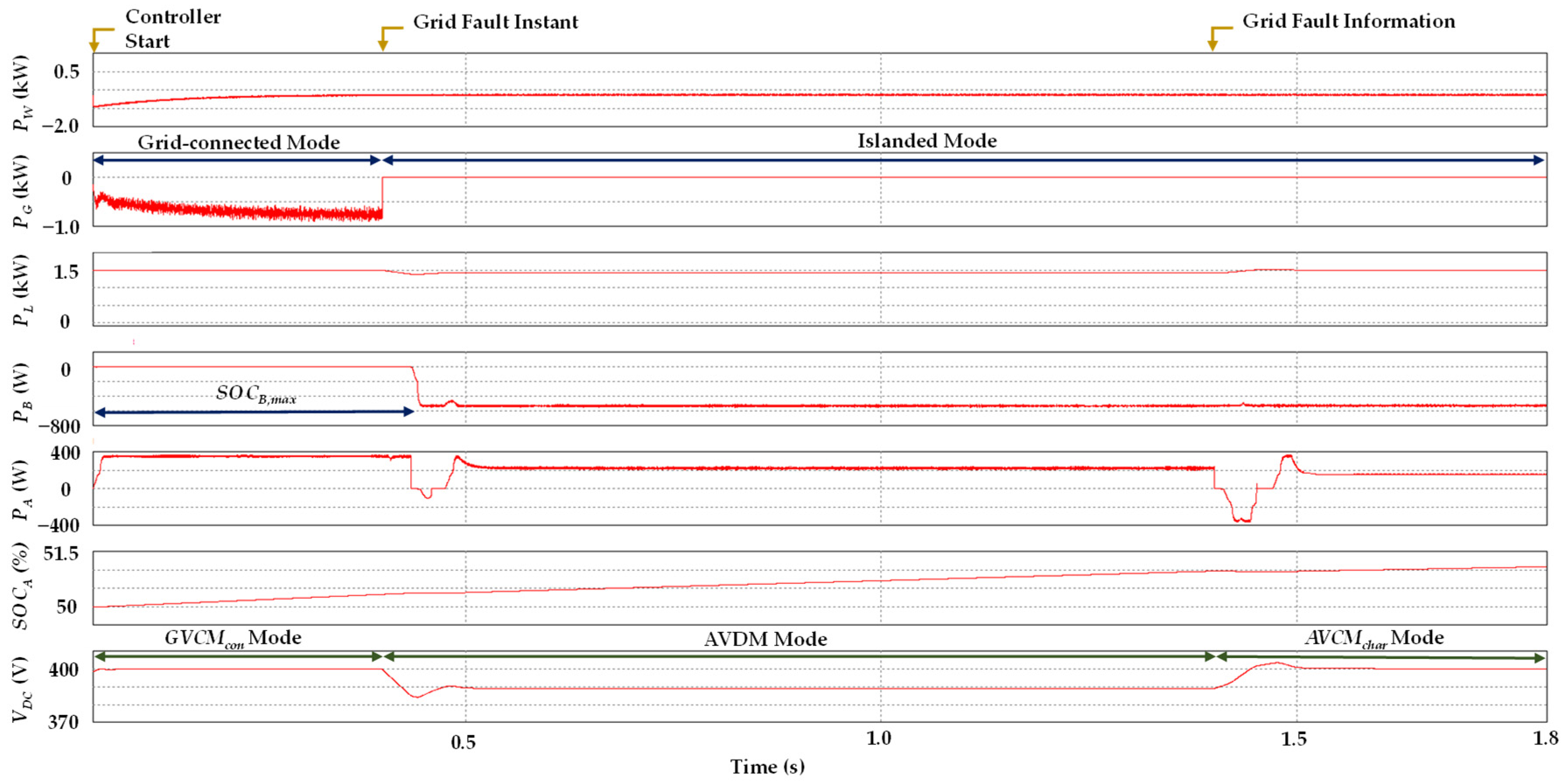
To demonstrate not only the scalability but also the seamless power management of the proposed scheme under transmission time delays, Figure 15 shows the simulation results in case of grid fault detection delay when the AESS agent regulates DCV.
The DCMG control starts in the grid-connected mode with S O C B in the maximum, and S O C A in the region between S O C A , m i n and S O C A , m a x . The utility grid agent regulates DCV at V D C n o m via G V C M c o n mode. The wind turbine, battery, and AESS agents operate in MPPT, IDLE, and A C C M c h a r modes, respectively.
At t = 0.4 s, the grid fault occurs. However, all the agents recognize that the DCMG system operates in the distributed grid-connected mode because of communication time delays. As soon as V D C falls to V D C L , the wind turbine, battery, and AESS agents switch operations to the droop control mode to maintain the power balance. Once the grid fault information is identified by all agents at t = 1.4 s, the AESS agent operation is changed from AVDM to A V C M c h a r mode to regulate DCV at V D C n o m , and the battery and wind turbine agents operate in B C C M c h a r and MPPT modes, respectively, in the distributed islanded mode.

6. Experimental Results

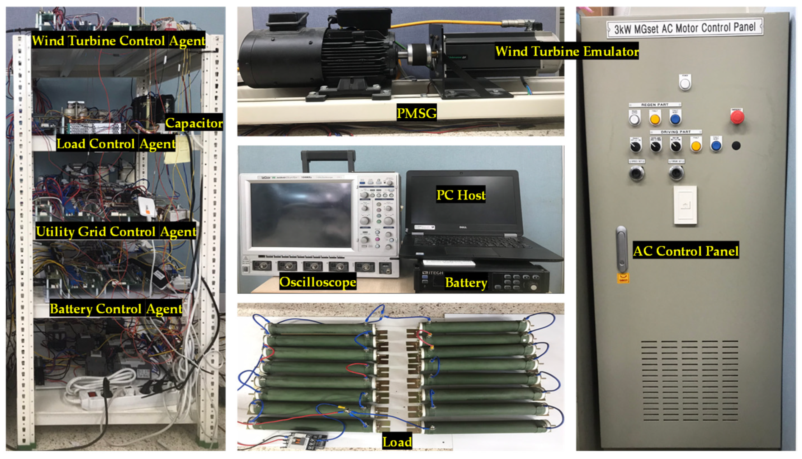
An experimental distributed DCMG setup, as shown in Figure 16, is employed to demonstrate the feasibility of the proposed distributed control scheme. The experimental DCMG system consists of four power electronic converters for interface with the utility grid, battery, wind turbine, and load agents. The utility grid agent is connected to a three-phase main grid through a transformer and bidirectional AC/DC converter with an LCL filter. The wind turbine agent is composed of a PMSG coupled with an induction machine to emulate the wind turbine power, in which the mechanical output power is delivered to the DC-link through a unidirectional AC/DC converter. The battery and AESS agents employ bidirectional interleaved DC/DC converters to connect to a bidirectional DC power source which is utilized as a battery. The magnetic contactor is used to change the operation modes in the load. Digital signal processor (DSP) TMS 320F28335 is utilized in each power agent to implement the proposed power management scheme for a distributed DCMG with minimum DCLs under transmission delays. Experimental results are presented in the case of grid-connected mode, islanded mode, and transmission time delays with the system parameters listed in Table 2.

6.1. Case of Load Shedding Process

Figure 17 shows the experimental results of the proposed control strategy for a distributed DCMG in the islanded mode in case of low battery SOC and load shedding. Figure 17a presents the steady-state responses, in which the DCV is regulated by the battery agent in BVCMdis mode. Because the supplied wind power is less than the demand load power, the battery agent regulates DCV at V D C n o m by BVCMdis mode to achieve the power balance. In this situation, the wind turbine and load agents operate in MPPT and normal modes, respectively.
Figure 17b shows the operating mode transitions from BVCMdis to load shedding mode and from load shedding to the BVCMchar mode. In this figure, as soon as the battery SOC reaches to S O C B , m i n , the battery agent stops injecting the power to DC-link. Because the load agent needs to absorb more power than the power sources in DCMG, V D C drops significantly. When V D C falls to V D C L i m i t , the load shedding mode is activated to avoid the collapse of the DCMG system. As a result of load shedding, V D C increases beyond V D C n o m . Then, to use the remaining power for battery charging, the battery agent regulates DCV at V D C n o m by B V C M c h a r mode while the wind turbine keeps MPPT mode. Figure 17c shows the steady-state responses of the distributed DCMG with the battery agent in BVCMchar mode.

6.2. Transition from Grid-Connected to Islanded Mode without Grid Fault Detection Delay

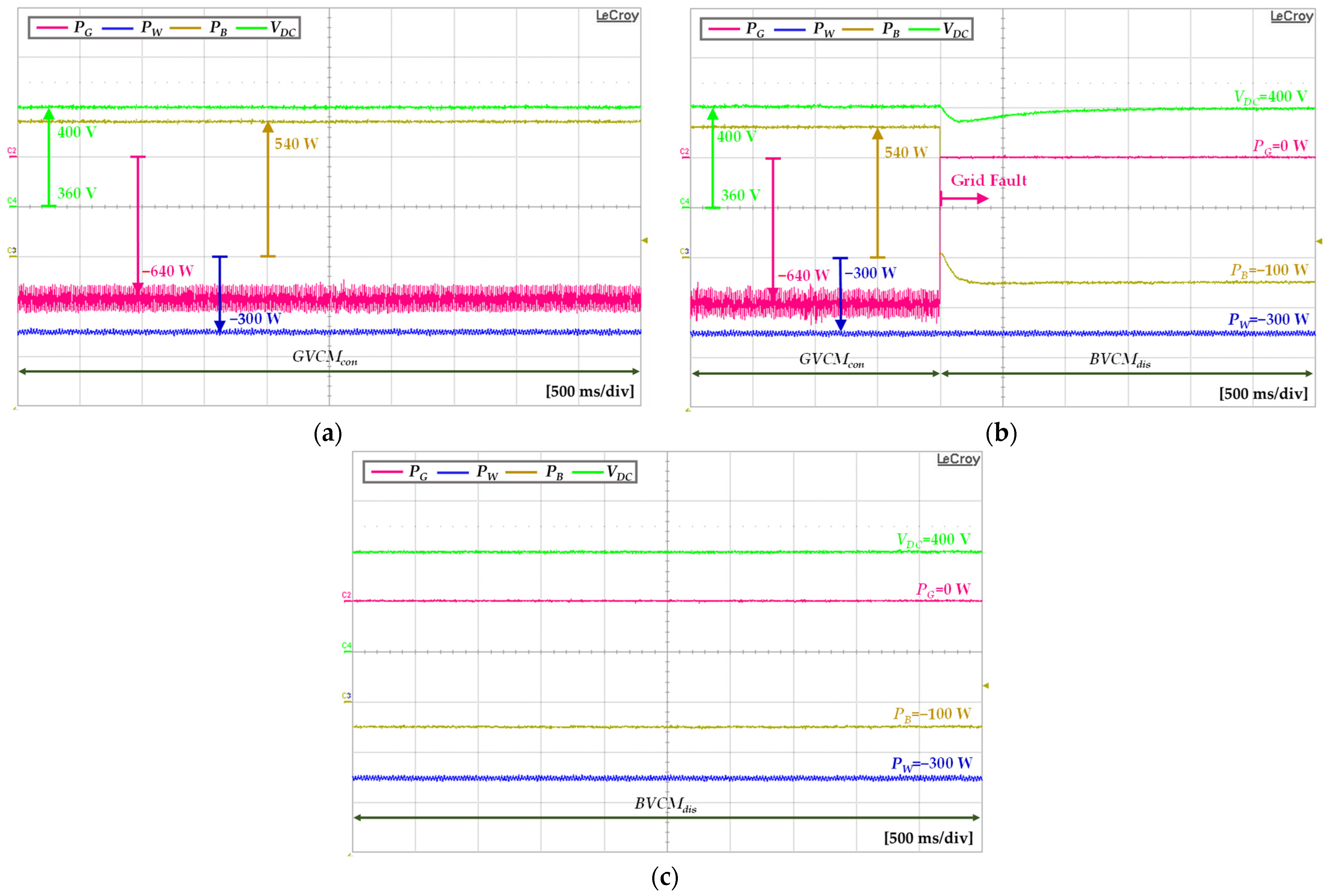
To demonstrate the voltage stabilization performance without the transmission time delays of grid fault, the experimental results of the proposed control strategy in case of the transition from grid-connected to the islanded mode are presented in Figure 18. Figure 18a presents the steady-state responses in which the DCV is regulated by the utility grid agent in the GVCMcon mode. In this situation, the wind turbine and battery agents operate in MPPT and BCCMchar modes, respectively.
Figure 18b shows the operating mode transition from GVCMcon to BVCMdis mode. When the wind turbine agent receives the data D G W , which represents that the utility grid fault occurs from the utility grid agent without transmission time delays, the DCMG system switches operation to islanded mode. Because the generated wind power is less than the demand load and S O C B is in the region between S O C B , m i n   and S O C B , m a x , the battery agent changes the operating mode from BCCMchar to BVCMdis to regulate DCV at V D C n o m . In this situation, the wind turbine and load agents still operate in MPPT and normal modes, respectively. Figure 18c shows the steady-state responses of the distributed DCMG with the battery agent in BVCMdis in the islanded mode.

6.3. Case of Grid Fault Detection Delay

To verify the seamless power management feature of the proposed scheme under transmission time delays, the experimental results in the case of grid fault detection delay are presented in Figure 19 and Figure 20.
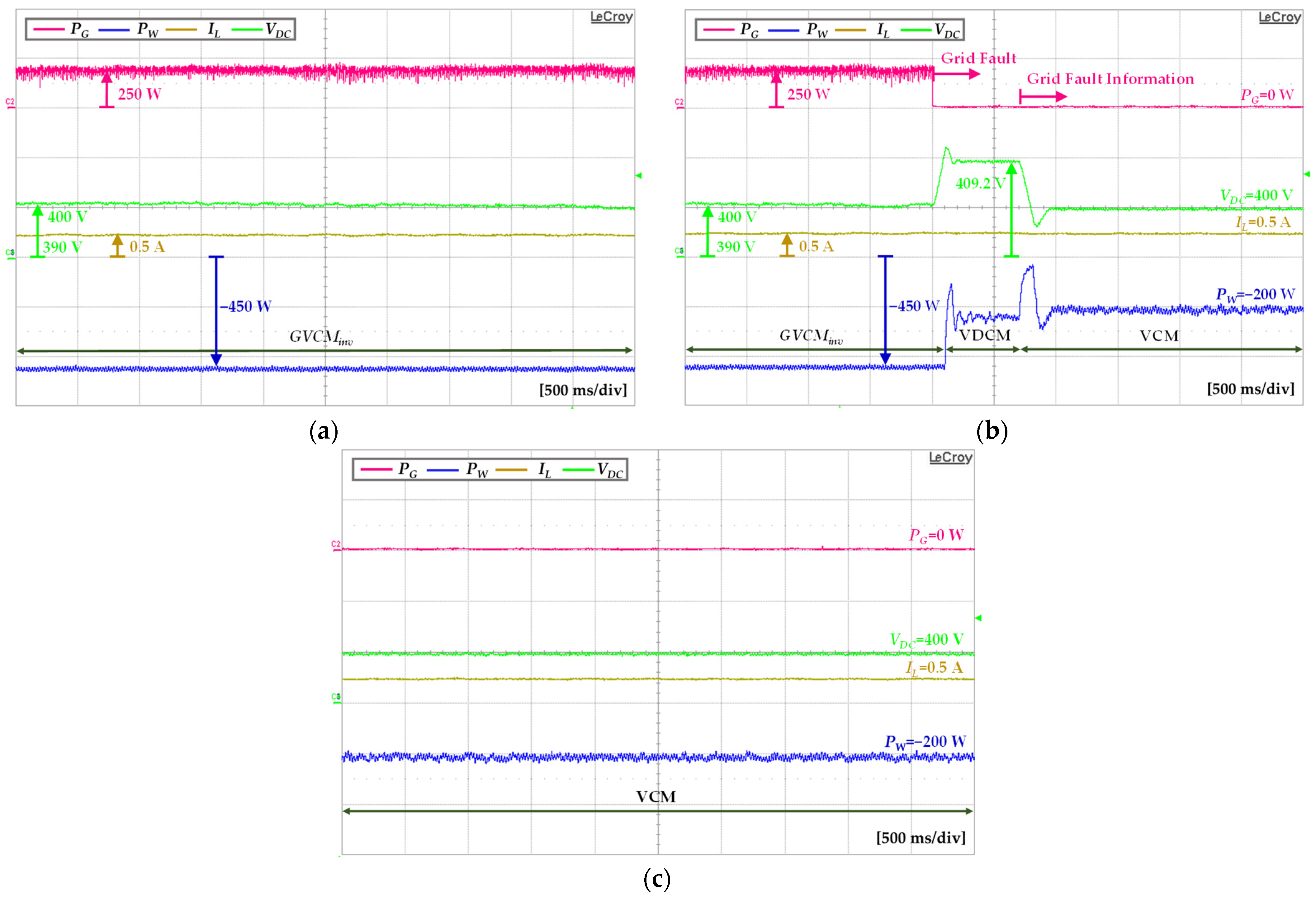
Figure 19a shows the steady-state responses in which the DCV is regulated by the utility grid agent in GVCMinv in the grid-connected mode. In this situation, only load 1 is connected to the DC-link, the battery agent operates in the IDLE mode with S O C B , m a x , and the utility grid absorbs the power from the DC-link to regulate DCV at V D C n o m .
Figure 19b shows the operating mode transition from GVCMinv to VDCM mode, and from VDCM to VCM mode. When the grid fault occurs, all the agents recognize that the DCMG system operates in the distributed grid-connected mode because of communication time delays, which causes V D C to rise rapidly. As soon as V D C reaches V D C H , the wind turbine and battery agents switch the operation to the droop control mode. As a result, the wind turbine agent changes from MPPT to VDCM mode to regulate DCV while the battery agent keeps IDLE mode. Once the grid fault information is properly transmitted to the wind turbine agent, the DCV is controlled at V D C n o m via VCM in the distributed islanded mode. The steady-state responses of the distributed DCMG in VCM mode are shown in Figure 19c.
Figure 20 shows the experimental results of the proposed scheme in the case of grid fault detection delay when the battery agent regulates DCV. The utility grid agent regulates DCV at V D C n o m by GVCMcon mode in steady-state, as shown in Figure 20a. The wind turbine and battery agents operate in MPPT and B C C M c h a r modes, respectively.
When there exists a grid fault detection delay, the communication data D G W set to one is still transmitted to the wind turbine agent even if the utility grid agent has been disconnected from DCMG due to a fault. As soon as V D C falls to V D C L , the droop control mode is utilized to maintain the voltage stabilization by the battery and wind turbine agents, as shown in Figure 20b. In this situation, the battery agent changes operation from B C C M c h a r to BVDM mode to regulate DCV while the wind turbine agent keeps MPPT mode. When the grid fault information is identified by other power agents, the battery agent switches operation to B V C M d i s mode to regulate DCV at V D C n o m in the distributed islanded mode. Figure 20c shows the steady-state responses of the distributed DCMG in B V C M d i s of the battery agent in the distributed islanded mode.

6.4. Case of AESS Agent Involvement

To demonstrate the scalability and flexibility of the proposed distributed DCMG structure, Figure 21 presents the experimental results when an AESS agent is connected to the existing DCMG system with minimal DCLs. Figure 21a shows the steady-state responses of the distributed DCMG in BVCMdis mode. Because the generated wind power is lower than the sum of the demand load and maximum AESS charging powers, the battery agent regulates the DCV at V D C n o m by supplying the power to the DC-link. The AESS, wind turbine, and load agents operate in A C C M c h a r , MPPT, and normal modes, respectively.
Figure 21b shows the operating mode transition from BVCMdis to AVCMdis mode in the islanded mode. As soon as the battery SOC falls to S O C B , m i n , the battery agent stops supplying the power to DC-link. Instead, the AESS agent changes the operating mode from ACCMchar to AVCMdis to maintain voltage stabilization. In this case, the wind turbine and load agents still operate in MPPT and the normal modes, respectively. Figure 21c shows the steady-state responses of the distributed DCMG in AVCMdis in case of an AESS agent involvement.
To compare the performance of the proposed distributed control scheme between the simulation and experimental results, Table 3 lists the maximum voltage error of the DCV ( V D C , e r r o r m a x ) between V D C and V D C n o m in both the simulation and experiment results when the operation mode is switched in the distributed system. The transient behavior caused by the operation mode transition is smoother in the simulation than in the experiment with a smaller value of V D C , e r r o r m a x .

7. Conclusions

This paper has presented seamless power management for a distributed DCMG with minimum DCLs under transmission time delays. The DCLs topology is proposed for the construction of distributed DCMG system not only to optimize the DCMG system cost but also to minimize the data size in an exchange packet. According to information gathered from DCLs and local measurements, the operating modes of local agents in a distributed DCMG are determined appropriately to maintain a power balance under various conditions. During normal operation, the proposed scheme works as a distributed control scheme either in the grid-connected or islanded mode to take advantage of the distributed control method. To maintain seamless power management and voltage stabilization even under transmission time delays such as grid fault detection delays and grid recovery detection delays, the operating modes of each agent in a DCMG system are switched to a decentralized scheme based on the droop control method. When the utility grid information is properly identified by all power agents after a transmission time delay, the DCMG system changes the operation from the decentralized control scheme to distributed control scheme to maintain the DCV at the nominal value. The control strategies of local power agents under transmission time delays are presented by the flow charts, which is a computationally efficient and simple way to implement them in a real embedded system. In addition, to demonstrate flexibility and scalability, the proposed scheme also presents power management with minimum DCL topology when an AESS agent is involved in an existing distributed DCMG system. Simulation and experimental results for the proposed distributed DCMG structure have been presented under a variety of conditions to verify the effectiveness of the proposed seamless power management strategy.

Author Contributions

D.T.T., A.F.H. and K.-H.K. conceived the main concept of the DC microgrid control structure and developed the entire system. D.T.T. and A.F.H. carried out the research and analyzed the numerical data with guidance from K.-H.K., D.T.T., A.F.H. and K.-H.K. collaborated in the preparation of the manuscript. All authors have read and agreed to the published version of the manuscript.

Funding

This research was supported by Basic Science Research Program through the National Research Foundation of Korea (NRF) funded by the Ministry of Education (NRF-2019R1A6A1A03032119). This work was supported by the National Research Foundation of Korea (NRF) grant funded by the Korea government (MSIT) (NRF-2022R1F1A1064350).

Institutional Review Board Statement

Not applicable.

Informed Consent Statement

Not applicable.

Data Availability Statement

Data sharing is not applicable to this article.

Conflicts of Interest

The authors declare no conflict of interest.

Abbreviations

ACAlternating current
AESSAdditional ESS agent
AVDMVoltage droop control mode by AESS agent
BVDMVoltage droop control mode by battery agent
DCDirect current
DCMGDC microgrid
DCVDC-link voltage
DCLsDigital communication links
DSPDigital signal processor
ESSEnergy storage system
IDLEIdle mode by the battery or the utility grid agent
MPPTMaximum power point tracking
PIProportional integral
PMSGPermanent magnet synchronous generator
PVPhotovoltaic
RESRenewable energy source
SOCState of charge
VCMDCV control by the wind turbine agent
VDCMVoltage droop control mode by wind turbine agent
A C C M c h a r Constant current control by AESS charging
A V C M c h a r DCV control by AESS charging
A V C M d i s DCV control by AESS discharging
B C C M c h a r Constant current control by battery charging
B C C M d i s Constant current control by battery discharging
B V C M c h a r DCV control by battery charging
B V C M d i s DCV control by battery discharging
C dc Capacitance of DC-link
CfFilter capacitance of LCL filter
D A B Data information from the AESS agent to the battery agent
D B A Data information from the battery agent to the AESS agent
D B W Data information from the battery agent to the wind turbine agent
D G W Data information from the utility grid agent to the wind turbine agent
D W B Data information from the wind turbine agent to the battery agent
D W L Data information from the wind turbine agent to the load agent
f G Grid frequency
G V C M i n v DCV control by inverter mode of the utility grid agent
G V C M c o n DCV control by converter mode of the utility grid agent
i Number of operating loads
JPMSG inertia
LAConverter filter inductance of AESS agent
LBConverter filter inductance of battery agent
LdqPMSG dq-axis inductance
LWConverter filter inductance of wind turbine agent
L1Inverter-side inductance of LCL filter
L2Grid-side inductance of LCL filter
n Number of loads in a DCMG
P A , c h a r m a x Maximum AESS charging power
P A , d i s m a x Maximum AESS discharging power
P B , c h a r m a x Maximum battery charging power
P B , d i s m a x Maximum battery discharging power
P W   max Maximum power of the wind turbine agent
PAExchange power between DC-link and AESS agent
PBExchange power between DC-link and battery agent
PGExchange power between DC-link and utility grid agent
PLPower absorbed by load agent
PL1Power of load 1
PL2Power of load 2
PWGeneration power by wind turbine agent
R A Droop characteristic of AESS agent
R B Droop characteristic of battery agent
R W Droop characteristic of wind turbine agent
R S PMSG stator resistance
R1Parasitic resistance in L 1
R2Parasitic resistance in L 2
S O C A , m a x Maximum AESS state of charge
S O C A , m i n Minimum AESS state of charge
S O C A AESS state of charge
S O C B , m a x Maximum battery state of charge
S O C B , m i n Maximum battery state of charge
S O C B Battery state of charge
s A State of the AESS agent
s B State of the battery agent
s G State of the utility grid agent
s W State of the wind turbine agent
V A max Maximum AESS voltage
V B max Maximum battery voltage
V G   rms Grid voltage
V D C , B L Low DCV level of battery agent
V D C , G r e f DC-link reference voltage of the utility grid agent
V D C , e r r o r Error of V D C and V D C n o m
V D C , e r r o r m a x Maximum voltage error between V D C and V D C n o m
V D C Measured DCV
V D C C o n DCV state
V D C H Highest DCV level
V D C L Lowest DCV level
V D C L i m i t Limited DCV level
V D C n o m Nominal DCV
V D C p r e DCV in the previous time step
VAAESS voltage
VBBattery voltage
ψ PMSG flux linkage

References

  1. Saeed, M.H.; Fangzong, W.; Kalwar, B.A.; Iqbal, S. A review on microgrids’ challenges & perspectives. IEEE Access 2021, 9, 166502–166517. [Google Scholar]
  2. Espina, E.; Llanos, J.; Burgos-Mellado, C.; Cárdenas-Dobson, R.; Martínez-Gómez, M.; Sáez, D. Distributed control strategies for microgrids: An overview. IEEE Access 2020, 8, 193412–193448. [Google Scholar] [CrossRef]
  3. Lee, J.; Guo, J.; Choi, J.K.; Zukerman, M. Distributed energy trading in microgrids: A game-theoretic model and its equilibrium analysis. IEEE Trans. Ind. Electron. 2015, 62, 3524–3533. [Google Scholar] [CrossRef]
  4. Dou, C.; Yue, D.; Zhang, Z.; Ma, K. MAS-based distributed cooperative control for DC microgrid through switching topology communication network with time-varying delays. IEEE Trans. Syst. J. 2019, 13, 615–624. [Google Scholar] [CrossRef]
  5. Nejabatkhah, F.; Li, Y.W. Overview of power management strategies of hybrid AC/DC microgrid. IEEE Trans. Power Electron. 2015, 30, 7072–7089. [Google Scholar] [CrossRef]
  6. Yu, C.; Zhou, H.; Lu, X.; Lai, J.; Liu, G.-P. Distributed optimal synchronization rate control for AC microgrids under event-triggered mechanism. IEEE Trans. Power Syst. 2021, 36, 1780–1793. [Google Scholar] [CrossRef]
  7. Li, J.; Liu, Y.; Wu, L. Optimal operation for community-based multi-party microgrid in grid-connected and islanded modes. IEEE Trans. Smart Grid 2018, 9, 756–765. [Google Scholar] [CrossRef]
  8. Liu, Y.; Yuen, C.; Ul Hassan, N.; Huang, S.; Yu, R.; Xie, S. Electricity cost minimization for a microgrid with distributed energy resource under different information availability. IEEE Trans. Ind. Electron. 2015, 62, 2571–2583. [Google Scholar] [CrossRef]
  9. Habibullah, A.F.; Padhilah, F.A.; Kim, K.-H. Decentralized control of DC microgrid based on droop and voltage controls with electricity price consideration. Sustainability 2021, 13, 11398. [Google Scholar] [CrossRef]
  10. Xia, Y.; Wei, W.; Peng, Y.; Yang, P.; Yu, M. Decentralized coordination control for parallel bidirectional power converters in a grid-connected DC microgrid. IEEE Trans. Smart Grid 2018, 9, 6850–6861. [Google Scholar] [CrossRef]
  11. Li, X.; Jiang, W.; Wang, J.; Wang, P.; Wu, X. An autonomous control scheme of global smooth transitions for bidirectional DC-DC converter in DC microgrid. IEEE Trans. Energy Convers. 2021, 36, 950–960. [Google Scholar] [CrossRef]
  12. Meng, L.; Dragicevic, T.; Roldan-Perez, J.; Vasquez, J.C.; Guerrero, J.M. Modeling and sensitivity study of consensus algorithm-based distributed herarchical control for DC microgrids. IEEE Trans. Smart Grid 2016, 7, 1504–1515. [Google Scholar] [CrossRef] [Green Version]
  13. Lee, S.-J.; Choi, J.-Y.; Lee, H.-J.; Won, D.-J. Distributed coordination control strategy for a multi-microgrid based on a consensus algorithm. Energies 2017, 10, 1017. [Google Scholar] [CrossRef] [Green Version]
  14. Dehkordi, N.M.; Sadati, N.; Hamzeh, M. Distributed robust finite-time secondary voltage and frequency control of islanded microgrids. IEEE Trans. Power Syst. 2017, 32, 3648–3659. [Google Scholar] [CrossRef]
  15. Fan, Z.; Fan, B.; Peng, J.; Liu, W. Operation loss minimization targeted distributed optimal control of DC microgrids. IEEE Syst. J. 2021, 15, 5186–5196. [Google Scholar] [CrossRef]
  16. Guo, F.; Xu, Q.; Wen, C.; Wang, L.; Wang, P. Distributed secondary control for power allocation and voltage restoration in islanded DC microgrids. IEEE Trans. Sustain. Energy 2018, 9, 1857–1869. [Google Scholar] [CrossRef]
  17. Zhao, B.; Zhang, X.; Chen, J.; Wang, C.; Guo, L. Operation optimization of standalone microgrids considering lifetime characteristics of battery energy storage system. IEEE Trans. Sustain. Energy 2013, 4, 934–943. [Google Scholar] [CrossRef]
  18. Al-Hanahi, B.; Ahmad, I.; Habibi, D.; Masoum, M.A.S. Charging infrastructure for commercial electric vehicles: Challenges and future works. IEEE Access 2021, 9, 121476–121492. [Google Scholar] [CrossRef]
  19. Padhilah, F.A.; Kim, K.-H. A power flow control strategy for hybrid control architecture of DC microgrid under unreliable grid connection considering electricity price constraint. Sustainability 2020, 12, 7628. [Google Scholar] [CrossRef]
  20. Tian, G.; Zheng, Y.; Liu, G.; Zhang, J. SOC balancing and coordinated control based on adaptive droop coefficient algorithm for energy storage units in DC microgrid. Energies 2022, 15, 2943. [Google Scholar] [CrossRef]
  21. Hoang, K.D.; Lee, H.-H. Accurate power sharing with balanced battery state of charge in distributed DC microgrid. IEEE Trans. Ind. Electron. 2019, 66, 1883–1893. [Google Scholar] [CrossRef]
  22. Morstyn, T.; Savkin, A.V.; Hredzak, B.; Agelidis, V.G. Multi-agent sliding mode control for state of charge balancing between battery energy storage systems distributed in a DC microgrid. IEEE Trans. Smart Grid 2018, 9, 4735–4743. [Google Scholar] [CrossRef] [Green Version]
  23. Chen, X.; Shi, M.; Sun, H.; Li, Y.; He, H. Distributed cooperative control and stability analysis of multiple DC electric springs in a DC microgrid. IEEE Trans. Ind. Electron. 2018, 65, 5611–5622. [Google Scholar] [CrossRef]
  24. Zhao, C.; Sun, W.; Wang, J.; Li, Q.; Mu, D.; Xu, X. Distributed cooperative secondary control for islanded microgrid with Markov time-varying delays. IEEE Trans. Energy Convers. 2019, 34, 2235–2247. [Google Scholar] [CrossRef]
  25. Zhang, R.; Hredzak, B. Distributed finite-time multiagent control for DC microgrids with time delays. IEEE Trans. Smart Grid 2018, 10, 2692–2701. [Google Scholar] [CrossRef]
  26. Huang, B.; Liu, L.; Li, Y.; Zhang, H. Distributed optimal energy management for microgrids in the presence of time-varying communication delays. IEEE Access 2019, 7, 83702–83712. [Google Scholar] [CrossRef]
  27. Chaudhuri, B.; Majumder, R.; Pal, B.C. Wide-area measurement-based stabilizing control of power system considering signal transmission delay. IEEE Trans. Power Syst. 2004, 19, 1971–1979. [Google Scholar] [CrossRef] [Green Version]
  28. Yan, H.; Zhou, X.; Zhang, H.; Yang, F.; Wu, Z.-G. A novel sliding mode estimation for microgrid control with communication time delays. IEEE Trans. Smart Grid 2019, 10, 1509–1520. [Google Scholar] [CrossRef]
  29. Xing, L.; Guo, F.; Liu, X.; Wen, C.; Mishra, Y.; Tian, Y.-C. Voltage restoration and adjustable current sharing for DC microgrid with time delay via distributed secondary control. IEEE Trans. Sustain. Energy 2021, 12, 1068–1077. [Google Scholar] [CrossRef]
  30. Dong, M.; Li, L.; Nie, Y.; Song, D.; Yang, J. Stability analysis of a novel distributed secondary control considering communication delay in DC microgrids. IEEE Trans. Smart Grid 2019, 10, 6690–6700. [Google Scholar] [CrossRef]
  31. Nguyen, T.V.; Kim, K.-H. An improved power management strategy for MAS-based distributed control of DC microgrid under communication network problems. Sustainability 2020, 12, 122. [Google Scholar] [CrossRef]
  32. Nguyen, T.V.; Kim, K.-H. Power flow control strategy and reliable DC-Link voltage restoration for DC Microgrid under grid fault conditions. Sustainability 2019, 11, 3781. [Google Scholar] [CrossRef]
  33. Morstyn, T.; Hredzak, B.; Agelidis, V.G. Communication delay robustness for multi agent state of charge balancing between distributed AC microgrid storage systems. In Proceedings of the 2015 IEEE Conference on Control Applications (CCA), Sydney, Australia, 21–23 September 2015. [Google Scholar]
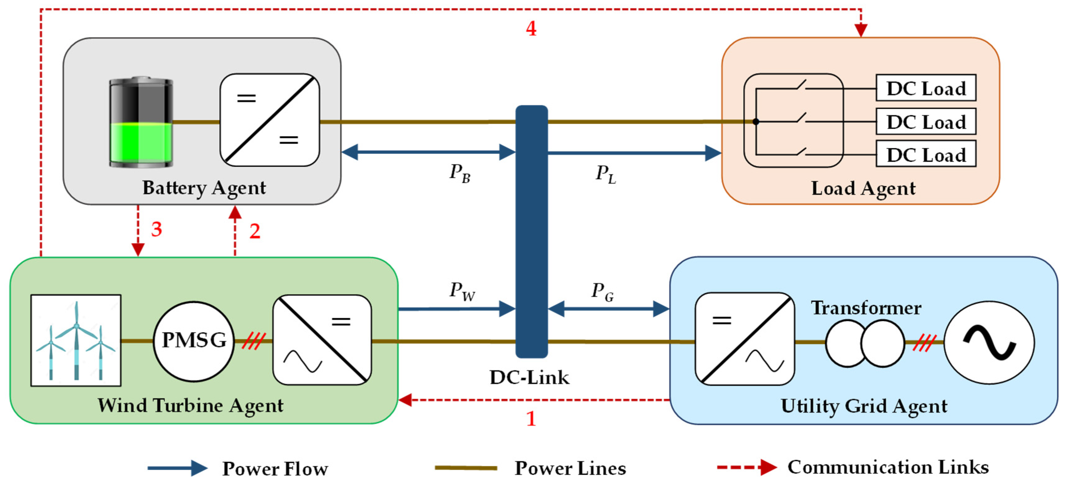
Figure 1. Configuration of the DCMG.
Sustainability 14 14739 g001
Figure 2. System communication topology in a DCMG.
Sustainability 14 14739 g002
Figure 3. Control strategy of the utility grid agent.
Sustainability 14 14739 g003
Figure 4. Control strategy of the wind turbine agent.
Sustainability 14 14739 g004
Figure 5. Control strategy of the battery agent.
Sustainability 14 14739 g005
Figure 6. Control strategy of the load agent.
Sustainability 14 14739 g006
Figure 7. V-P droop curves for wind turbine and battery agents in the case of transmission time delays.
Sustainability 14 14739 g007
Figure 8. Control strategy of the battery agent in the event of the AESS agent involvement.
Sustainability 14 14739 g008
Figure 9. Control strategy of an AESS agent.
Sustainability 14 14739 g009
Figure 10. V-P droop curves in the event of the AESS agent involvement under transmission time delays.
Sustainability 14 14739 g010
Figure 11. Simulation results for the transition from grid-connected mode to islanded mode without grid fault detection delay.
Sustainability 14 14739 g011
Figure 12. Simulation results in case of grid fault detection delay.
Sustainability 14 14739 g012
Figure 13. Simulation results in case of grid recovery detection delay when the battery agent regulates DCV.
Sustainability 14 14739 g013
Figure 14. Simulation results in load shedding when the AESS agent regulates DCV in islanded mode. (a) Without grid fault detection delay; (b) with grid fault detection delay.
Sustainability 14 14739 g014
Figure 15. Simulation results in case of grid fault detection delay when AESS agent regulates DCV.
Sustainability 14 14739 g015
Figure 16. Configuration of experimental DCMG test setup.
Sustainability 14 14739 g016
Figure 17. Experimental results of the proposed control strategy for a distributed DCMG in the islanded mode in case of low battery SOC and load shedding. (a) Steady-state responses in BVCMdis mode; (b) operating mode transitions from BVCMdis to load shedding mode, and from load shedding to BVCMchar mode; (c) steady-state responses in BVCMchar mode.
Sustainability 14 14739 g017
Figure 18. Experimental results of the proposed control strategy for a distributed DCMG in case of the transition from grid-connected to islanded mode without grid fault detection delay. (a) Steady-state responses in GVCMcon mode; (b) operating mode transition from GVCMcon to BVCMdis mode; (c) steady-state responses in BVCMdis mode.
Sustainability 14 14739 g018
Figure 19. Experimental results of the proposed control strategy for a distributed DCMG in case of grid fault detection delay when the wind turbine agent regulates DCV. (a) Steady-state responses in GVCMinv mode; (b) operating mode transitions from GVCMinv to VDCM mode, and from VDCM to VCM mode; (c) steady-state responses in VCM mode.
Sustainability 14 14739 g019
Figure 20. Experimental results of the proposed control strategy for a distributed DCMG in case of grid fault detection delay when the battery agent regulates DCV. (a) Steady-state responses in GVCMcon mode; (b) operating mode transitions from GVCMcon to BVDM mode and from BVDM mode to BVCMdis mode; (c) steady-state responses in BVCMdis mode.
Sustainability 14 14739 g020
Figure 21. Experimental results of the proposed control strategy for a distributed DCMG in case of AESS agent involvement in the islanded mode. (a) Steady-state responses in BVCMdis mode; (b) Operating mode transitions from BVCMdis to AVCMdis mode; (c) steady-state responses in AVCMdis mode.
Sustainability 14 14739 g021
Table 1. Detailed Descriptions of DCLs.
Communication LinkExchange DataData TypeData Information
1 D G W Binary0: Utility grid agent does not regulate DCV.
1: Utility grid agent regulates DCV.
2 D W B Binary0: Wind turbine and utility grid agents do not regulate DCV.
1: Wind turbine/utility grid agent regulates DCV.
3 D B W Binary0: Battery agent does not regulate DCV.
1: Battery agent regulates DCV.
4 D W L Binary0: Load agent operates in the normal/load reconnecting mode.
1: Load agent operates in the normal/load-shedding mode.
5 D B A Binary0: Wind turbines, utility grids, and battery agents do not regulate DCV.
1: Wind turbine/utility grid/battery agent regulates DCV.
6 D A B Binary0: AESS agent does not regulate DCV.
1: AESS agent regulates DCV.
Table 2. System parameters of a distributed DCMG system.
Power AgentsParametersSymbolValue
Utility grid agentGrid voltage V G   rms 220 V
Grid frequency f G 60 Hz
Transformer Y / Δ T380/220 V
Inverter-side inductance of LCL filter L 1 1.7 mH
Parasitic resistance in L 1 R 1 0.5 Ω
Grid-side inductance of LCL filter L 2 1.7 mH
Parasitic resistance in L 2 R 2 0.5 Ω
Filter capacitance of LCL filter C f 4.5 μF
Grid fault detection delay time-0.5–1.0 s
Grid recovery detection delay time-0.5–1.0 s
Wind turbine agentPMSG stator resistance R S 0.64 Ω
PMSG dq-axis inductance L dq 0.82 mH
PMSG number of poles p 6
PMSG inertia J 0.111 kgm2
PMSG flux linkage ψ 0.18 Wb
Converter filter inductance L W 7 mH
Maximum power of the wind turbine agent P W   max −3000 W
Battery agentMaximum SOC S O C B , m i n 90%
Minimum SOC S O C B , m i n 20%
Rated capacityC30 Ah
Maximum charging power P B , c h a r m a x 540 W
Maximum discharging power P B , d i s m a x −540 W
Maximum voltage V B max 180 V
Converter filter inductance L L B 7 mH
AESS agentMaximum SOC S O C A , m a x 90%
Minimum SOC S O C A , m i n 20%
Rated capacityC30 Ah
Maximum charging power P A , c h a r m a x 360 W
Maximum discharging power P A , d i s m a x −360 W
Maximum voltage V A max 180 V
Converter filter inductance L L B 7 mH
Load agentPower of load 1 P L 1 200 W
Power of load 2 P L 2 200 W
Priority level: load 1 > load 2--
DC-linkNominal DCV V D C n o m 400 V
Highest DCV level V D C H 410 V
Low DCV level of battery agent V D C , B L 390 V
Lowest DCV level V D C L 385 V
Limited DCV level V D C L i m i t 380 V
Capacitance C DC 4 mF
Table 3. Maximum voltage error of the DCV in simulation and experiments.
V D C , e r r o r m a x Simulation Experiment
Load shedding process0.175%1.050%
Transition from grid-connected mode to islanded mode without transmission time delay0.200%1.000%
Grid fault detection delay when the wind turbine agent regulates DCV0.125%1.050%
Grid fault detection delay when the battery agent regulates DCV0.025%0.625%
AESS involvement regulates DCV0.450%0.925%
Publisher’s Note: MDPI stays neutral with regard to jurisdictional claims in published maps and institutional affiliations.