Abstract
This paper proposes a method of energy storage capacity planning for improving offshore wind power consumption. Firstly, an optimization model of offshore wind power storage capacity planning is established, which takes into account the annual load development demand, the uncertainty of offshore wind power, various types of power sources and line structure. The model aims at the lowest cost of investment, operation and maintenance of the system, and takes lower than a certain abandoned wind level as the strict constraint to obtain two parameters of power capacity and energy capacity of energy storage on the source side. Secondly, taking a coastal power grid as a typical case, the energy storage capacity planning method is verified. Finally, the key factors affecting offshore wind power consumption are summarized, and the sensitivity analysis is carried out from the point of view of the transmission protocol of the transmission lines outside the province and the capacity allocation of the tie lines in the province. This study will be helpful for the planning and operation of the high-proportion of offshore wind energy power systems.
1. Introduction
With the development of the economy, fossil energy is decreasing and environmental pollution is increasing day by day. In order to alleviate the pressure of energy shortages and environmental deterioration, various countries are committed to the development and utilization of clean energy. The proposal of the carbon peaking and carbon neutrality goals demonstrates China’s determination to actively respond to climate change and achieve high-quality economic development. To further accelerate the development and utilization of non-fossil energy, especially new energy represented by wind and solar energy, is an important measure to achieve the arduous task of the carbon peaking and carbon neutrality goals.
Compared with other clean energy sources, wind power has greater development advantages and competitive potential. In the last 10 years, global onshore wind power has achieved rapid development, and the development of onshore wind power in some countries has become saturated. At present, there is an urgent demand for offshore wind power development and application all over the world [1]. China’s offshore wind power has great development potential and good development prospects. To develop a high-quality offshore wind power industry and accelerate the development of offshore wind power from near-sea to deep-sea to far-sea, promoting the large-scale, intensive and sustainable development of offshore wind power is an important support to promote the adjustment of China’s energy structure and achieve the carbon peaking and carbon neutrality goals [2]. Compared with onshore wind power, offshore wind power has three outstanding characteristics: (1) The offshore wind energy resources in the southeast coastal areas of China are abundant and close to the power load center, which is convenient for the consumption and utilization of the power grid. However, transmission cables need to be configured; (2) The overall output level of offshore wind farms is higher, with higher annual power generation utilization hours; (3) The transmission mode of offshore wind power is more flexible and does not need to occupy land resources.
The cost of transmission cable is high, and it is often difficult to send it complete. On the one hand, offshore wind power connected to the grid for operation will cause abandoned wind due to transmission congestion in part of the overall output. On the other hand, it will bring severe challenges to the peak regulation of the power grid. The lack of peak regulation capacity of the power grid leads to abandoned wind. The installation of an energy storage system is flexible, and the configuration of energy storage for an offshore wind power station can promote it to become a high-quality power supply. The source-side energy storage mainly works out a charge and discharge scheme to stabilize the fluctuation of its output power to achieve a higher proportion of offshore wind power consumption. However, there are some problems, such as the high cost of the energy storage configuration, the mismatch between energy storage technology and offshore applications, and so on. The improper use of energy storage equipment limits the appropriate absorption of wind power and increases the cost. The optimal allocation of energy storage capacity has always attracted much attention, and domestic and foreign researchers have carried out a lot of research on this issue.
The current research is mainly focused on energy storage capacity planning [3,4,5,6] and wind–storage operation optimization [7,8,9,10], and there is little research in [11,12] considering the interaction between the energy storage system planning and operation at the same time; a two-layer collaborative optimization model for energy storage capacity planning and operation is proposed. Starting from the wind power delivery channel, based on multi-stage stochastic programming and sequential Monte Carlo simulation, an optimal energy storage allocation method for wind farm stations considering energy storage life loss and delivery channels is proposed in [13]. Based on the characteristics of the wind farm, references [14,15,16] determined the energy storage allocation method based on a wind power prediction error, wind farm generation curve deviation correction, and wind farm output smoothing, respectively, but the work done in these references does not take into account the influence of the power grid peak regulation capacity. References [17,18,19] put forward the optimal allocation method of energy storage from the point of view of the influence of insufficient peak regulation capacity of grid-connected wind power, so that the power grid has a more downward regulation capacity to accept wind power, but only the performance of thermal power peak regulation is considered. The work done in these references does not consider the comprehensive effects of many types of power sources.
Reference [20] studies the feasibility and rationality of wind–storage combined power generation under current market conditions from the point of view of a technical and economic evaluation, which provides a reference for an optimal allocation in a wind–storage combined power generation system. References [21,22] fully consider the operation characteristics of the energy storage system and determine the energy storage allocation method based on the dynamic adjustment of charge state and a variable life model. The joint planning model of energy storage and the transmission network for improving the receptive capacity of wind power is established in [23], but the focus is on the power capacity of the energy storage, and the energy capacity is not mentioned. Based on the characteristics of offshore wind power, an optimal scheduling method for the joint operation of offshore wind power and seawater-pumped storage power stations is proposed in [24], but the work done in the reference only mentions optimization and does not involve the optimal allocation of offshore energy storage units. There is little research on offshore wind power and energy storage. A physical model combining offshore wind power generation with an underwater compressed air energy storage system was established in [25]. In [26], an optimal energy storage allocation model was constructed based on the improved scene clustering algorithm under the application scenario of smoothing the offshore wind power output fluctuation. A new multi-objective programming framework is proposed in [27] to determine the optimal capacity of battery energy storage systems in the cooperative operation of large offshore wind farms and battery energy storage systems. The cited references present the different technologies of energy storage. Their characteristics are shown in Table 1.

Table 1.
The characteristics of common energy storage types.
Pumped hydro storage is the most reliable, economical, large capacity and most mature energy storage device in the power system. It has the advantages of flexible start-up, fast climbing speed, peak cutting and valley filling, and it is an important part of the development of new energy. However, it depends on geographical conditions and needs high hydropower stations. It has a great impact on geography and terrain, and the construction cost is high. Large-scale battery energy storage systems can be used for power grid energy management and peak regulation, and the technology is quite mature. Moreover, it has a fast load response and daily regulation ability, so it is suitable for large-scale wind power generation.
This paper presents two innovative points: based on the idea of combining planning and operation through operation simulation, an optimization model of offshore wind energy storage capacity planning is established, which aims to minimize the total national economic expenditure of the system. It considers the offshore wind power transmission channel constraint and uses the abandoned wind rate below a certain level as a strict constraint. Further, based on 24 scenarios for the optimization model and the contour line of annual cost and the contour line of abandoned wind rate, an energy storage capacity planning method for improving offshore wind power consumption is proposed, which can obtain a reasonable economic and optimal energy storage configuration scheme quickly.
The rest of the paper is organized as follows. The optimization model of offshore wind energy storage capacity planning is established and the principal block diagram of the planning and optimization process is shown in Section 2. The case study and data analysis for the optimization model for offshore wind energy storage capacity planning are carried out and an energy storage capacity planning method for improving offshore wind power consumption is proposed in Section 3. Finally, Section 4 concludes the paper.
2. Model and Methods
At present, electrochemical energy storage systems are the most widely used technology on the source side of offshore wind farms. Small-scale battery storage systems are generally used in ships and offshore platforms, while large-scale battery storage systems are mainly used in islands and coastal areas. This paper takes electrochemical energy storage systems as an example to conduct relevant research on the energy storage technology of offshore wind farms [28,29,30,31,32,33].
The electrochemical energy storage for offshore wind farms is required to meet the applicable conditions of environmental temperature; it is not easy to maintain the working temperature of high-temperature sodium-sulfur batteries and liquid metal batteries in the sea environment. It is required that the mechanical moving parts of the energy storage device should be as few as possible, so as not to be damaged by corrosion or wave impact in the marine environment. The liquid flow battery should not be adopted because of its electrode characteristics with many such parts. It is required that the leakage of battery materials has no obvious harm to prevent pollution of the marine environment, so lead–acid batteries, lithium-ion batteries, seawater batteries and silver–zinc batteries can be used for offshore wind farms [34]. Offshore energy storage needs to be resistant to wind and wave impact, seawater immersion, seawater corrosion, and so on. Therefore, developing offshore energy storage systems tends to be more costly than developing onshore energy storage systems. It is necessary to configure suitable offshore energy storage capacities for offshore wind power to avoid excessive costs.
2.1. Optimization Model of Offshore Wind Energy Storage Capacity Planning
2.1.1. Objective Function
On the premise of satisfying the system demand and all kinds of constraint conditions, the system can minimize the total national economic expenditure in the whole planning period. The objective function of the model can be expressed as:
where Nm is the construction cycle of the newly invested energy storage power station, Ct is the investment cost of the newly invested energy storage power station at the beginning of the year t, and Fgt and Fkt are the fixed operation and maintenance costs and fuel costs of the system in year t, respectively. Ot is the outage loss cost of the system in year t, and Bt is the benefit obtained by the system in year t, except for power generation. NT is the number of planning years and i is the discount rate.
Taking the first year as the base year, when the construction process of the newly invested energy storage power station is simplified, it can be considered that the power station generates investment costs at the beginning of the first year of the planning period, and the loss of power outage and other benefits are ignored. The total calculated cost of the planning period can be equivalent to the annual cost. It means that the investment cost of the new power station at the beginning of the first year can be evenly allocated to each year of the planning period, and then added to the annual operating cost. Then the objective function can be expressed as:
Cess, the investment cost of the energy storage power station, can be expressed as:
where Pess and Eess are the rated power capacity and energy capacity of the energy storage, respectively, Tess is the charging and discharging time of energy storage, and λp and λe are the cost per unit power capacity and the cost per unit energy capacity, respectively.
The annual fixed operation and maintenance cost Fg consists of a conventional thermal power station Fg1 and an energy storage station Fg2, which can be expressed as:
where Cg1 is the total investment cost of a conventional thermal power station, αg1 is the annual fixed operation and maintenance cost rate of the power station, and αg2 is the fixed operation and maintenance cost of energy storage per unit power.
The thermal power station’s annual operating fuel cost Fk can be expressed as:
where Ek is the annual energy yield of a conventional thermal power station, and βk is the fuel cost of the unit energy yield of the power station.
2.1.2. Constraint
In comprehensively considering a variety of power supply types, including wind power, photovoltaic, hydropower, thermal power, pumped storage and new energy storage units, the electricity transmitted by the inter-provincial tie lines and the transmission lines outside the province can be classified into the load demand, and the constraint conditions to be met are shown in the following equations.
① Constraints on system power balance:
where Pesst represents the output of the newly invested energy storage system at time t, P0t represents the output of the original power station of the system at time t, LDt is the load value of the system at time t, and ρ and σ are the power consumption rate and system line loss rate, respectively.
② Maximum and minimum output constraints of power station:
where Pkmin and Pkmax are the minimum and maximum technical outputs of unit k.
③ Thermal power fuel consumption constraints:
where Eit is the generating capacity of the thermal power plant i at time t, Aiτ is the fuel consumption limit of power plant i in the period τ, and βi is the average fuel consumption per unit of power plant i.
④ Climbing constraints of thermal power units:
where URi and DRi are the loading and unloading rate of unit i, respectively, and Uit represents the start-stop state of thermal power unit i at time t, which is 0–1. The start-up is 1, and others are 0.
⑤ Constraints on the start and stop of thermal power units:
where TS and TO are the minimum shutdown and start-up time of the thermal power unit, respectively.
⑥ Constraints on the generating capacity of hydropower units:
where Ejt is the generating capacity of the hydropower plant j at time t, Wjτ is the available water limit of power plant j in the period τ, and βj is the average water consumption per unit of power plant j.
⑦ Constraints on pumped storage units:
where ηj is the pumping-power generation conversion efficiency of pumped storage power station j, and EjG and EjP are the generating capacity and pumping load capacity of the pumped storage power station j, respectively, within its dispatching period τ. The pumped power of a pumped storage power station at a certain period of time must be an integer multiple of its single capacity. CP.t is the pumping capacity of the pumped storage power station at time t, and PPS.P.N is the rated pumping capacity of the pumped storage unit.
⑧ Energy storage operation constraints:
where Pcmax_ESS and Pdmax_ESS are the maximum charge and discharge power, respectively. Pout_ESS is the real-time output power, and Et is the real-time energy capacity.
⑨ Standby constraints:
where N units are providing a certain reserve capacity, urN(t) represents the spinning reserve of N units at time t, α is the total reserve rate, and LDmax is the maximum load.
⑩ Offshore wind power transmission channel constraints:
where Ppass is the maximum transmission capacity of the offshore wind power transmission channel. PWN is the rated installed capacity of the offshore wind farm, and η is the transmission channel ratio.
2.2. Principal Block Diagram of Planning and Optimization Process
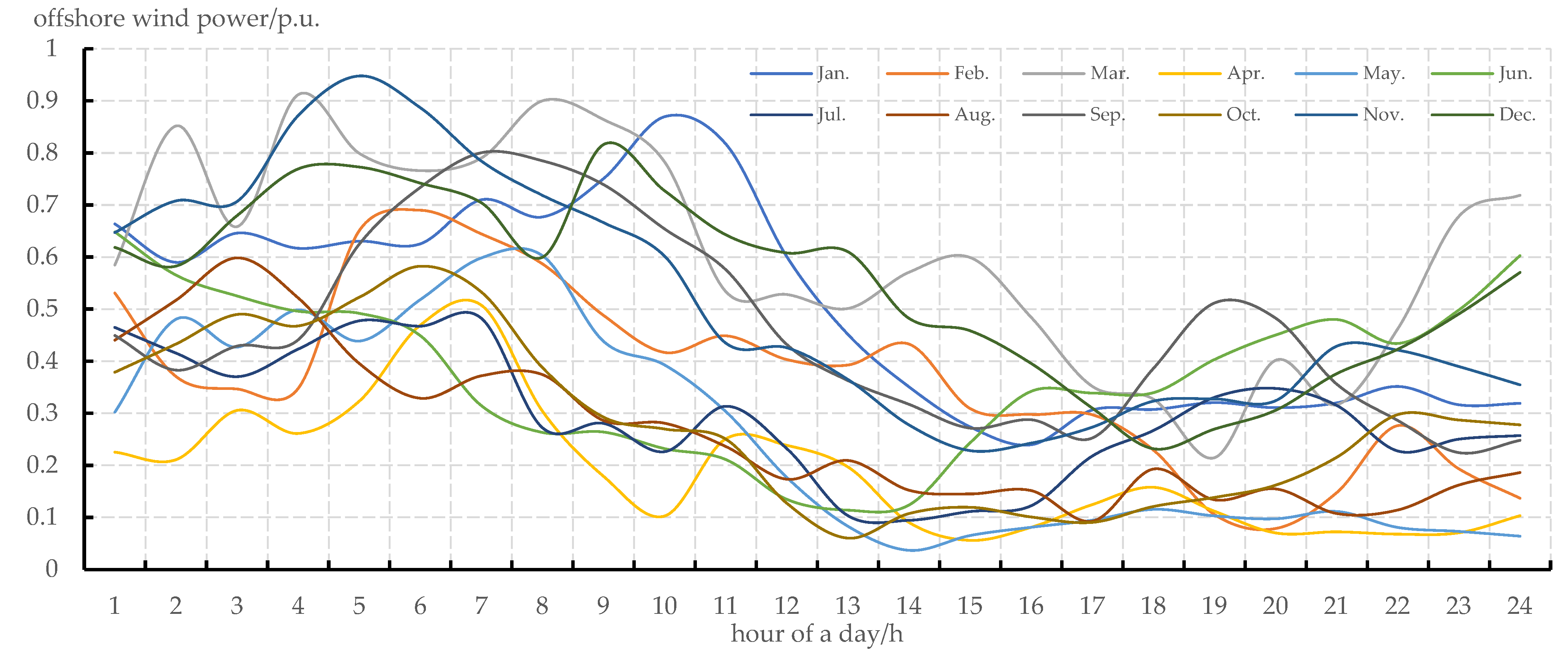
A typical case of a coastal power grid is taken to verify the effectiveness of the energy storage capacity planning method. First, the methods of cluster analysis and probabilistic modeling are adopted to consider the uncertainty of offshore wind power, and the annual output characteristic curves are shown in Figure 1.
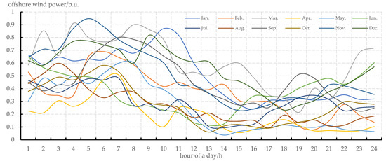
Figure 1.
Offshore wind power output curve clustering scenario set.
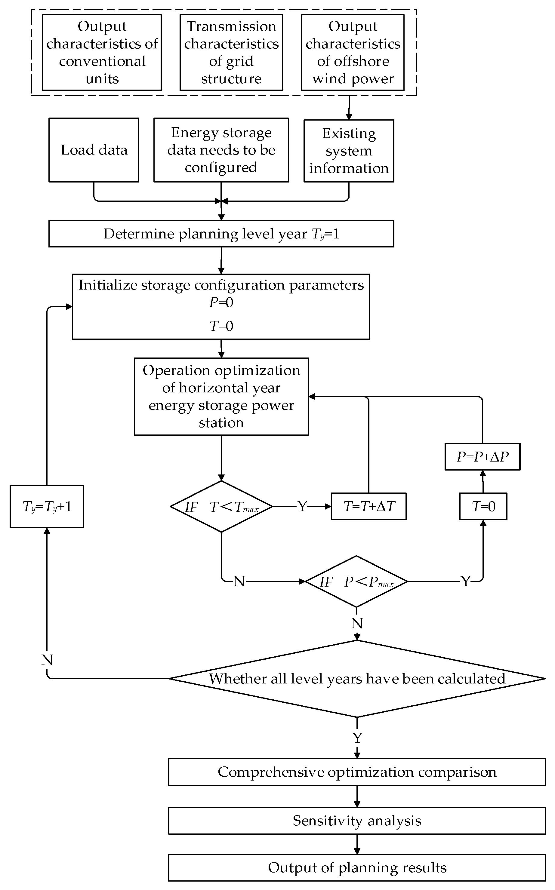
The principal block diagram of offshore wind power storage capacity planning and optimization is shown in Figure 2. The long-term operation data of the combined wind–storage system can be obtained through operation simulation, and the consumption index of offshore wind power can be calculated. After a comprehensive optimization comparison and sensitivity analysis, the optimal planning results can be outputted.
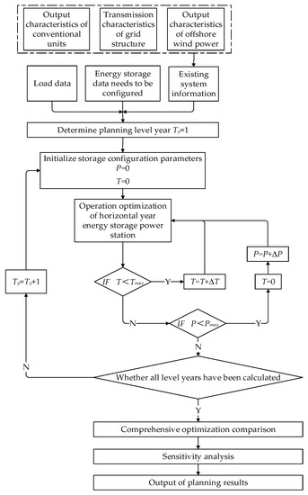
Figure 2.
Principal block diagram of offshore wind energy storage capacity planning and optimization.
3. Results and Discussion
3.1. Description of the Basic Conditions of the Example
It is expected that by 2025, the annual maximum load of the power grid in this coastal area will be 0.0111 billion kW, with a total power consumption of 59.2 billion kWh, and the total installed offshore wind power will reach 9176.5 MW. The transmission channel ratio η = 0.8, and this means that the maximum capacity of the transmission channel will be 7341.2 MW.
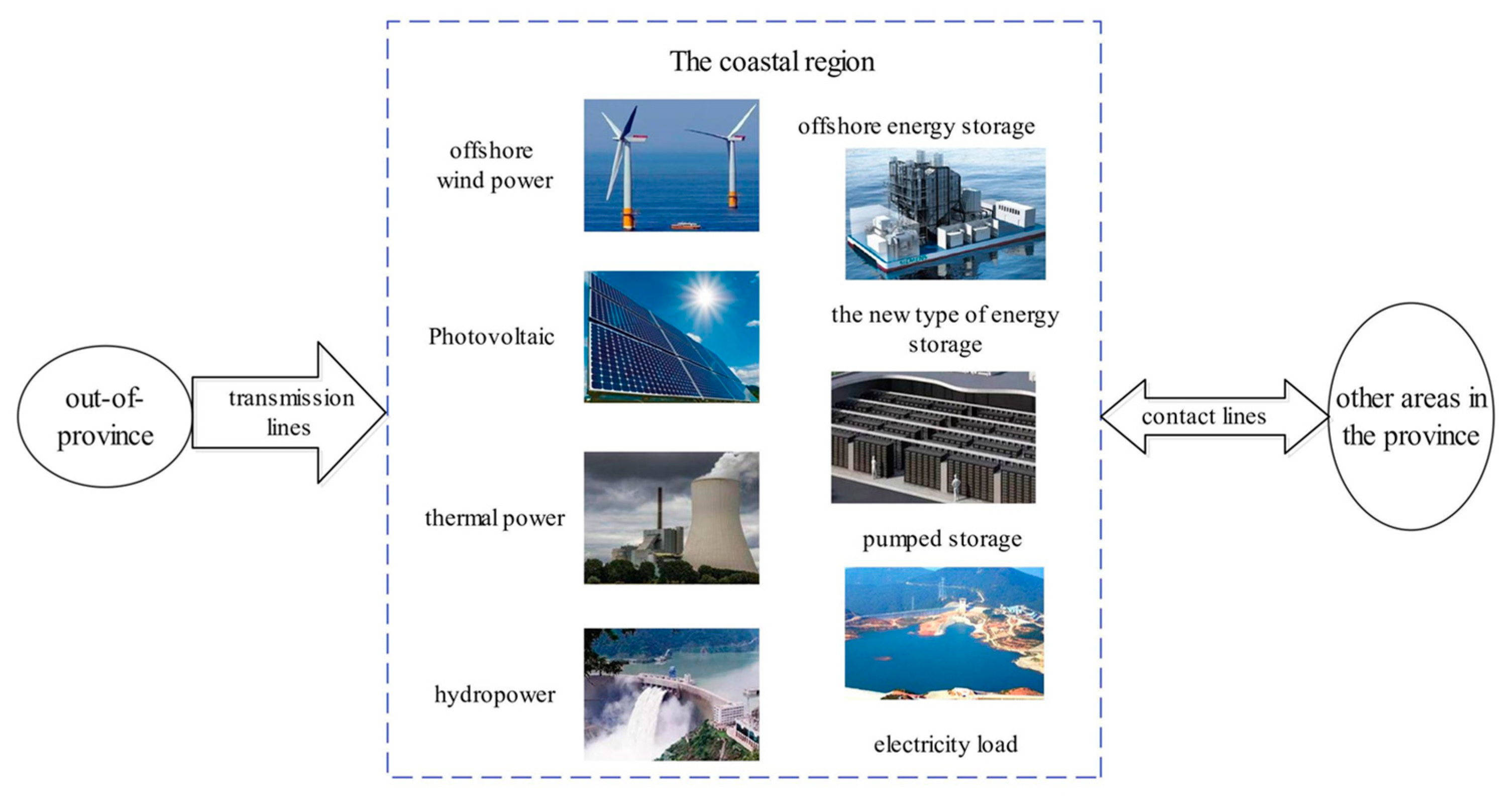
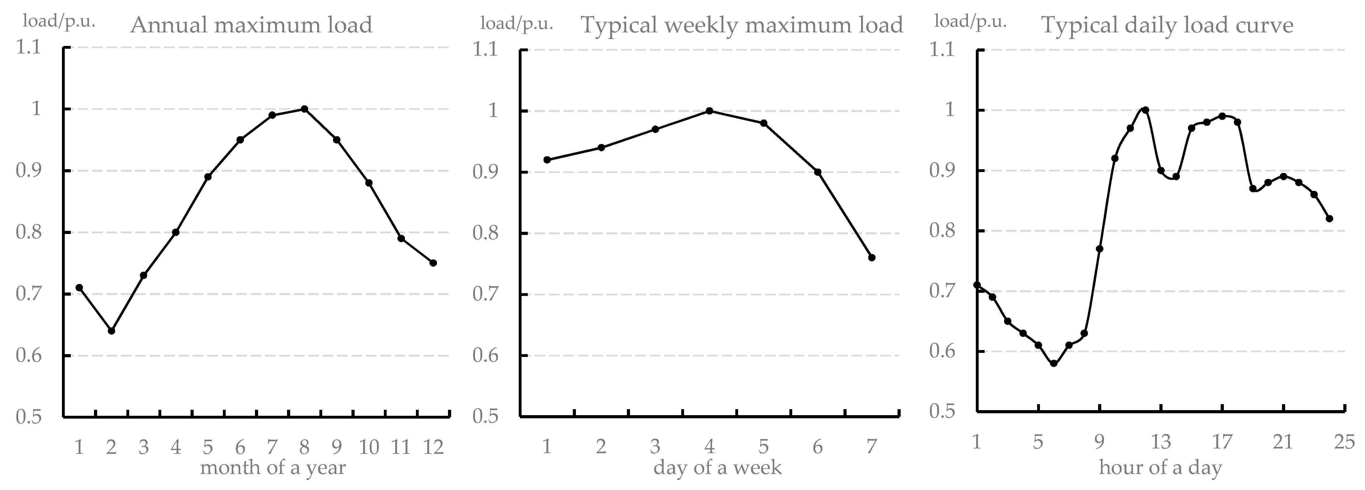
The multi-type power supply and line structure in this coastal area are shown in Figure 3. The installed capacity of the multi-type power supply corresponding to Figure 3 is shown in Table 2. The installed capacity of offshore energy storage needs to be planned and then configured. Load characteristics are described by an annual maximum load curve, typical weekly maximum load curve and typical daily load curve. Load data are shown in Figure 4.
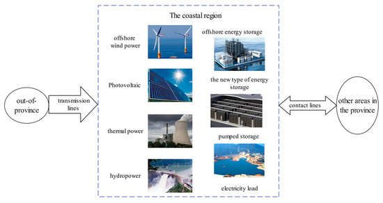
Figure 3.
Power supply and line structure in this coastal area.

Table 2.
The installed capacity of various power sources of the coastal power grid.
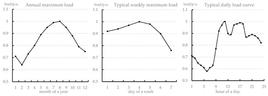
Figure 4.
Annual load characteristic curves.
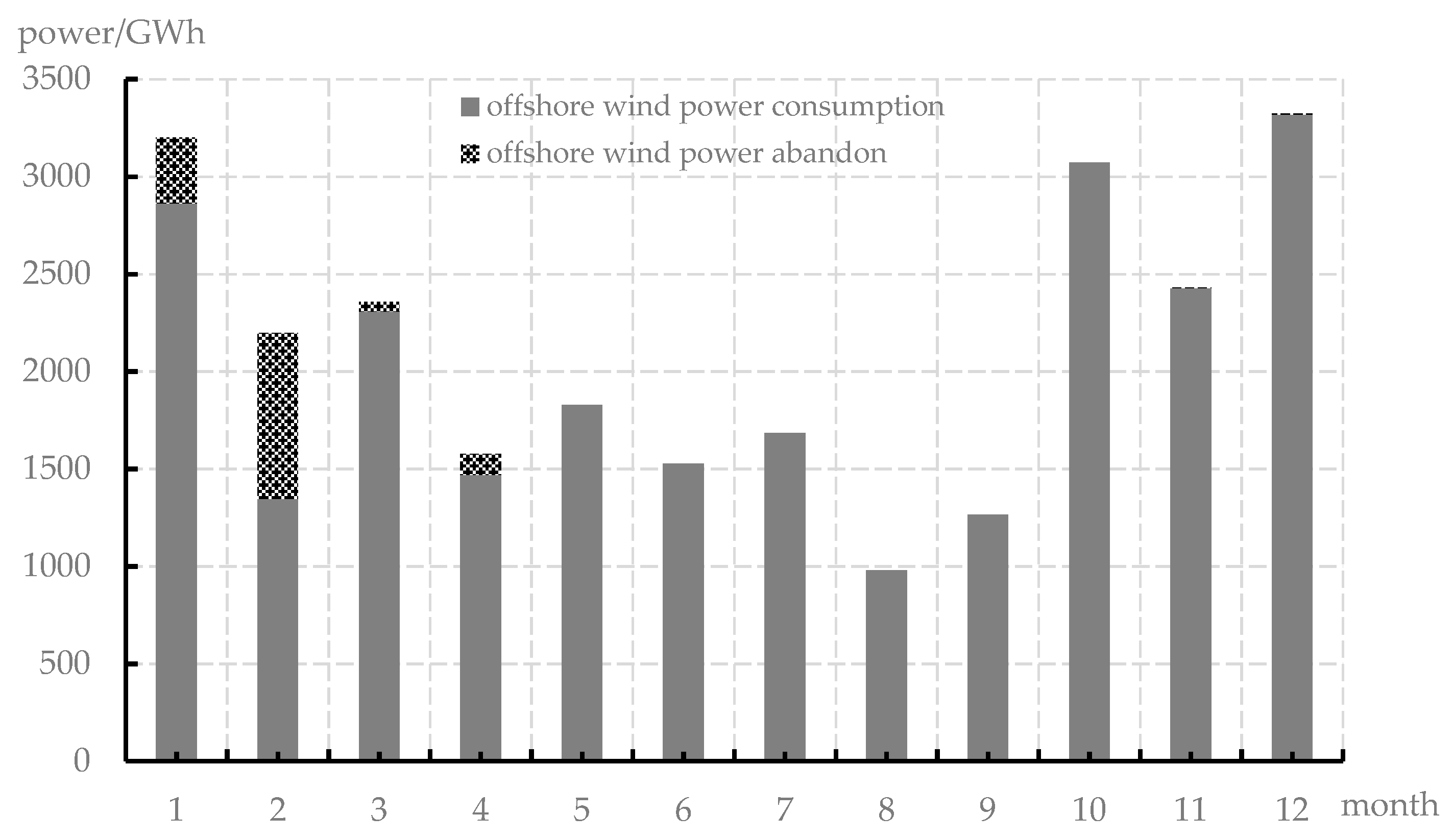
We used the Gurobi solver to solve the model in the MATLAB programming environment. The simulation was carried out with the year as the cycle and the day as the unit. Inputs should be the load curves and offshore wind power output curves of the coastal area based on historical data, combined with the power installation structure and the grid structure inside and outside of the province. The monthly statistics of offshore wind power and abandoned wind power in this coastal area can be obtained without new energy storage, as shown in Figure 5.
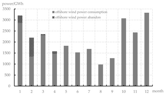
Figure 5.
Annual utilization of offshore wind power in this coastal area.
All of the offshore wind farms in this coastal area can generate 25,441.25 GWh of electricity in a year. The practical electricity is 24,085.76 GWh, and the abandoned wind power is 1355.49 GWh. The abandoned wind rate is 5.33%, and the utilization hours of offshore wind power are 2625 h. Further, the utilization hours of the transmission channels are 3281 h. It can be seen from Figure 5 that the abandoned wind power of offshore wind power is mainly concentrated from January to April, with the most serious abandoned wind in February and a little abandoned wind in November and December.
For lead–acid battery and lithium-ion battery energy storage systems, the cost coefficients per unit of energy capacity, per unit power capacity, the operation and maintenance costs and engineering life obtained, are shown in Table 3.

Table 3.
Related parameters of energy storage.
According to relevant parameters, the planning period is selected as 20 years, and the comprehensive discount rate for the whole society is 10%. According to the offshore wind energy storage capacity planning optimization model, the next step is to set up the energy storage configuration. The offshore wind farms are configured with an energy storage capacity of 10% to 40% of their rated installed capacity. Therefore, the rated power capacity of the energy storage system is described as 0.1~0.4 in the following. The installed capacity of energy storage under different configuration schemes is shown in Table 4. With daily cycle adjustments of energy storage devices, the charging and discharging time is set from 1 to 6 h, respectively, and the 24 energy storage configuration schemes are combined with different power P and charging and discharging time T.

Table 4.
Storage capacity configuration of offshore wind farms.
3.2. Example Analysis of Simulation Results
Based on the energy storage configuration scheme, the annual electricity balance of operation simulation from the planning level is conducted to obtain the operation simulation results of the coastal area. The relationship between the abandoned wind rate of the offshore wind power and the energy storage configuration scheme is shown in Table 5. Thus, with the further increase in new energy storage power capacity and energy capacity, the abandoned wind rate of offshore wind power gradually decreases.

Table 5.
Relationship between the abandoned wind rate of offshore wind power and the energy storage configuration scheme in this region.
Here, when the lithium-ion battery energy storage system with a scale of 917.65 MW/917.65 MWh is configured in the offshore wind farm of this coastal area, the annual cost is analyzed, as shown in Table 6.

Table 6.
Composition of annual expenses (104 Yuan).
Based on this, the relationship between different energy storage configuration schemes and the annual costs can be obtained, as shown in Table 7. It can be seen that with the further increase in new energy storage power capacity and energy capacity, the annual system costs gradually increase. Therefore, the decrease in the abandoned wind rate of offshore wind power is accompanied by an increase in the annual system cost. This paper studies the method to achieve the lowest annual cost while meeting the strict constraints below a certain curtailment level.

Table 7.
Annual total cost under different schemes.
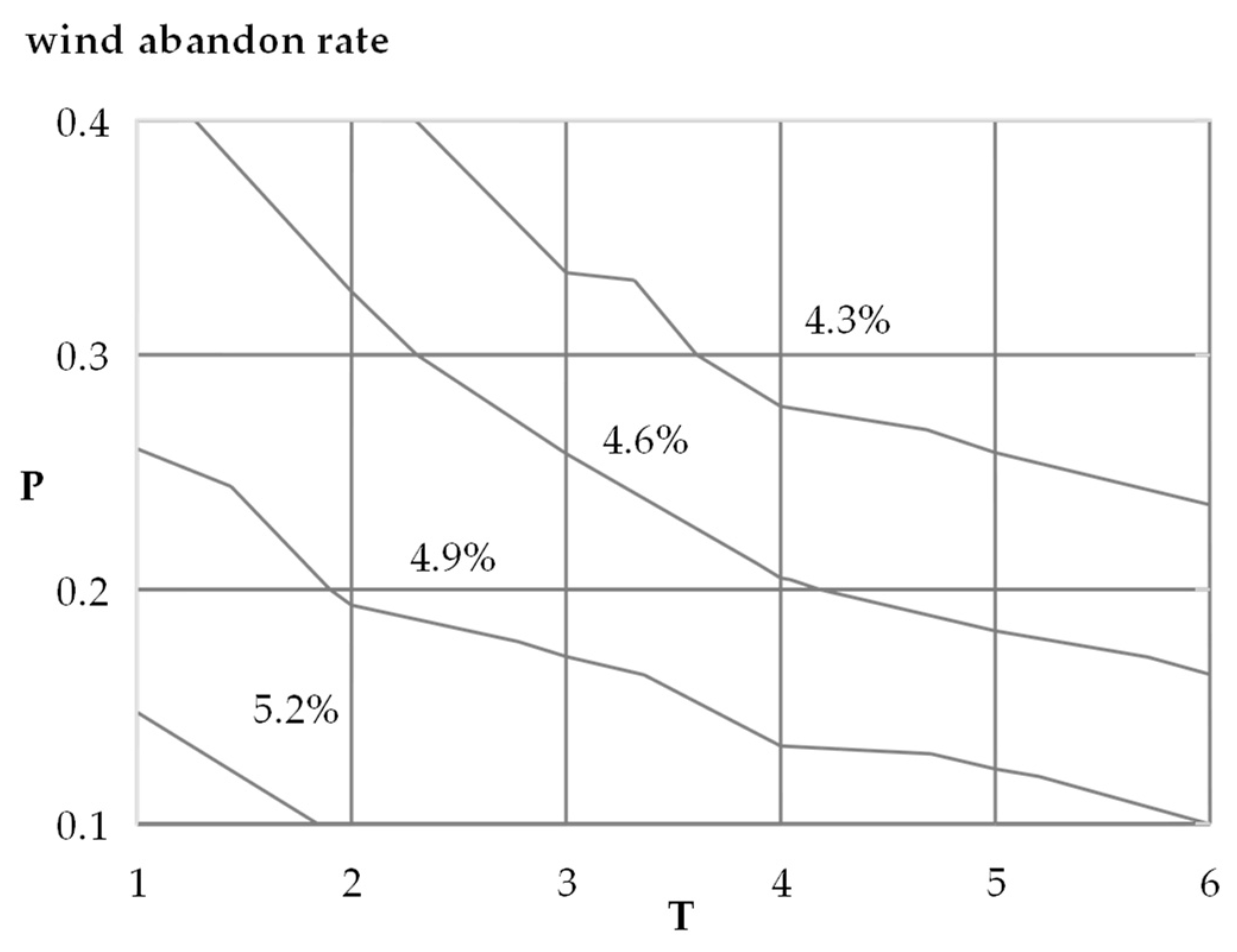
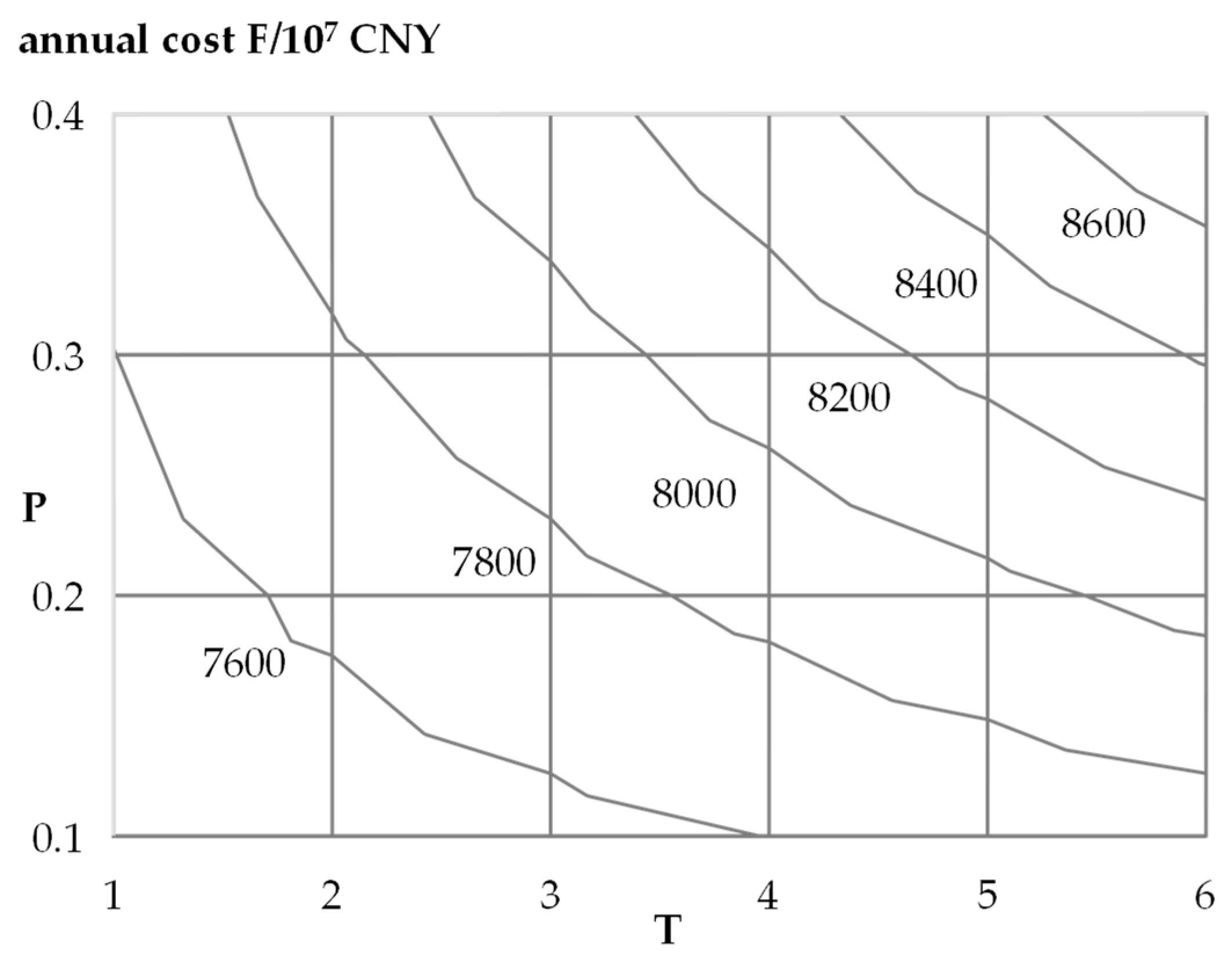
Based on Table 5 and Table 7, contour lines of wind curtailment rate and annual cost can be drawn on a two-dimensional plane, as shown in Figure 6 and Figure 7, respectively. The curve of wind curtailment rate indicates that different energy storage configurations can bring the same consumption effect of offshore wind power.
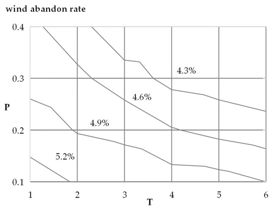
Figure 6.
Contour lines of abandoned wind rates of offshore wind power.
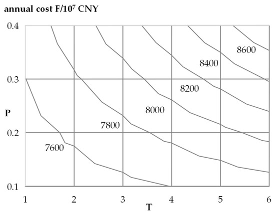
Figure 7.
Contour lines of the annual cost of the planning scheme.
In order to find the optimal economic scheme combined with the annual cost contour line, it can be known that when the abandoned wind rate is at a certain standard level, different annual cost contour lines are used to be tangent to the determined abandoned wind rate contour line, and the tangent point (power P, charge and discharge time T) is the best scheme.
In practical application, 5% of new energy is allowed to abandon power, which is scientifically reasonable. Therefore, the alternative energy storage configuration schemes are (0.3, 1), (0.2, 2), (0.1, 6), etc. According to this method, the best energy storage configuration scheme is (0.3, 1). It means that the scale of the lithium-ion battery energy storage system configured for the offshore wind farm with a total installed capacity of 9176.5 MW in the coastal area is 2752.95 MW/2752.95 MWh.
At this time, the practical electrical output of the offshore wind farm is 24,225.85 GWh. The abandoned wind power quantity is 1215.4 GWh, and the abandoned wind rate is 4.78%. The utilization hours of offshore wind power are 2640 h, and the utilization hours of the transmission channel are 3300 h. Further, the annual cost is 75.978 billion yuan.
For this study, only 24 scenarios, based on the optimization model to present the energy storage capacity allocation method, were used. By using fast computer calculation, the step size of the configuration scheme is further reduced. Based on the energy storage capacity planning method proposed in this paper, the configuration scheme with the best economy and applicability can be obtained more quickly and accurately.
3.3. Sensitivity Analysis
According to the above scheme, the configuration of a 2752.95 MW/2752.95 MWh lithium-ion battery energy storage system is relatively large in terms of the annual cost from 73.434 billion yuan to 75.978 billion yuan. This section studies the factors influencing the abandoned wind rate of offshore wind power from other perspectives, exploring feasible schemes to reduce the abandoned wind rate, and further allocating the source-side energy storage, paving the way to reduce the power capacity and energy capacity of the energy storage system configuration, thus reducing the investment costs and operation and maintenance costs, and improving the economic performance.
As shown in Figure 3, the consumption and utilization of offshore wind power in this coastal area are not only related to the installed scale of the power structure, including offshore wind power and energy storage but it is also affected by the transmission agreement signed with other provinces and the exchange of electricity in contact lines with other regions in the province. Therefore, a sensitivity analysis is carried out from the transmission agreement of the transmission lines outside of the province and the capacity allocation of the link line within the province.
3.3.1. Influence of Transmission Line Agreement
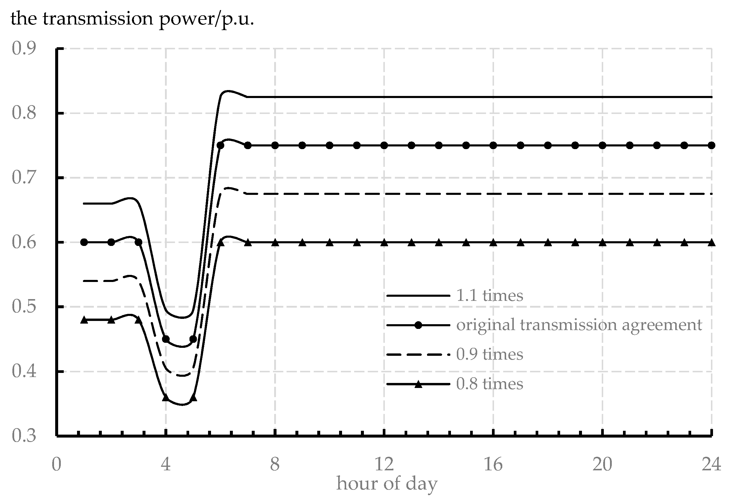
Out-of-province transmission line refers to a power transmission line from another province to the coastal area, with a maximum transmission capacity of 760 MW, which is sent to the coastal area in accordance with the transmission agreement signed with another province and given priority to use. Taking the daily transmission curve as an example, the transmission agreement can be adjusted to 1.1 times the original transmission agreement, the original transmission agreement, 0.9 times the original transmission agreement, and 0.8 times the original transmission agreement, as shown in Figure 8.
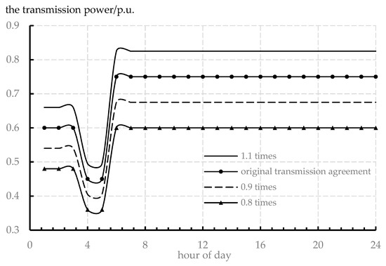
Figure 8.
Schematic diagram of different transmission protocols.
The original transmission agreement refers to the existing transmission agreement between the grid in the coastal area and another province. Under the existing transmission agreement, this paper adjusts it to 1.1 times, 0.9 times and 0.8 times, and then obtains the utilization of offshore wind power according to the optimization model, and analyzes the reasons for this situation. After the operation simulation, the changes in the offshore abandoned wind power rate under different transmission agreements can be compared and analyzed, and the results are shown in Table 8.

Table 8.
Utilization of offshore wind power under different transmission agreements.
Therefore, it can be seen that the electricity sent by the out-of-province transmission lines in this coastal area is too much, which affects the consumption and utilization of internal offshore wind power. Therefore, the transmission agreement can be optimized in the direction of reduction without additional cost.
3.3.2. Capacity Allocation of Tie Lines
There is a contact exchange between this coastal area and other areas A and B in the province. The maximum exchange capacity of the contact line between this coastal area and area A or area B is 3000 MW. This means that the total capacity of the external contact line in this coastal area is 6000 MW. This is because the total annual load demand power ratio of region A and region B is 1:1.2. Without changing the coastal area foreign link under the premise of a total exchange capacity of 6000 MW, the capacity ratio of the two contact lines is adjusted, and the changes in the abandoned wind rate of the offshore wind power under different capacity ratios of the contact line are compared and analyzed after the operation simulation. The results are shown in Table 9.

Table 9.
Utilization of offshore wind power under different capacity ratios of tie lines.
Therefore, the capacity ratio of the contact line can be optimized according to the load demand of the contact area. This is to reduce the maximum exchange capacity of the contact line between the coastal area and area A with low electrical demand, to limit and reduce the amount of electricity fed back to the coastal area, and promote the absorption and utilization of internal offshore wind power. Increasing the maximum exchange capacity of the link line between the coastal area and region B with a high electricity demand can effectively export the electrical power of the coastal area, and further export and utilize the offshore wind power that is difficult to be absorbed internally when needed.
On one hand, the abandonment of offshore wind power comes from transmission congestion in the transmission channel, and on the other hand, it comes from the lack of peak regulation capacity of the system. When the transmission protocol or tie line capacity ratio is optimized, the source-side energy storage can be further configured according to the method described in this paper, which can reduce the energy storage investment costs and operation and maintenance costs, and improve the economic performance.
4. Conclusions
This paper studies an energy storage capacity planning method for improving offshore wind energy consumption, and the conclusions are as follows:
- (1)
- An optimization model for offshore wind power storage capacity planning is established to seek an economic and reasonable energy storage power construction and configuration scheme within the planning period, on the premise of meeting the system’s annual load development needs and other various constraints;
- (2)
- Based on the power supply and line structure of the power grid in a coastal area, an example analysis of offshore wind power storage planning was conducted. According to this method, the best energy storage configuration scheme was (0.3, 1), at an annual cost of 75.978 billion yuan. In order to fully utilize offshore wind power and further improve economic performance, the sensitivity analysis of the abandoned wind rate of offshore wind power in this coastal area was carried out. The result proved that the reasonable optimization of the transmission agreement and the capacity ratio of tie lines can improve the acceptance capacity of the power grid to offshore wind power.
The results of this paper can provide some reference value for further research on capacity planning and the optimal operation of offshore wind energy storage. However, this paper sets a fixed value for the capacity of the offshore transmission channel, without joint planning of the offshore energy storage and the offshore transmission channel.
Author Contributions
Conceptualization, H.Y.; methodology, H.C.; software, X.Y. and S.L.; validation, X.Y. and S.L.; resources, H.C.; data curation, H.Y.; writing—original draft preparation, X.Y.; writing—review and editing, H.Y.; visualization, Y.L.; supervision, Y.L. All authors have read and agreed to the published version of the manuscript.
Funding
This research was funded by the Science and Technology Project of China Southern Power Grid Co., Ltd., grant number 037700KK52190012 (GDKJXM20198282) and supported by the Research and Development Plan in key areas of Guangdong Province, grant number 2021B0101230004.
Institutional Review Board Statement
Not applicable.
Informed Consent Statement
Not applicable.
Data Availability Statement
Not applicable.
Acknowledgments
The authors would like to thank the reviewers for their valuable comments on this research.
Conflicts of Interest
The authors declare no conflict of interest.
References
- Chi, Y.N.; Liang, W.; Zhang, Z.K.; Li, Y.; Jin, S.L.; Cai, X.; Hu, J.H.; Zhao, S.X.; Tian, W. An Overview on Key Technologies Regarding Power Transmission and Grid Integration of Large Scale Offshore Wind Power. Proc. CSEE 2016, 36, 3758–3771. [Google Scholar]
- Yao, G.; Yang, H.M.; Zhou, L.D.; Li, D.D.; Li, C.B.; Wang, J. Development Status and Key Technologies of Large-capacity Offshore Wind Turbines. Autom. Electr. Power Syst. 2021, 45, 33–47. [Google Scholar] [CrossRef]
- Song, Y.H.; Tan, Z.F.; Li, H.H.; Liu, W.Y. An Optimization Model Combining Generation Side and Energy Storage System With Demand Side to Promote Accommodation of Wind Power. Power Syst. Technol. 2014, 38, 610–615. [Google Scholar]
- Li, J.L.; Guo, B.Q.; Niu, M.; Xiu, X.Q.; Tian, L.T. Optimal Configuration Strategy of Energy Storage Capacity in Wind/PV/Storage Hybrid System. Trans. China Electrotech. Soc. 2018, 33, 1189–1196. [Google Scholar] [CrossRef]
- Dai, L.S.; Ye, C.J.; Fu, X.H.; Sun, K.; Bian, Q.Y.; Xin, H.H. Distributional Robust Joint Chance Constrained Optimal Capacity Installment of Energy Storage in Power System With High Penetration of Wind Power. Power Syst. Technol. 2017, 41, 769–777. [Google Scholar]
- Xu, G.D.; Cheng, H.Z.; Ma, Z.F.; Fan, S.L.; Fang, S.D.; Ma, Z.L. Overview of ESS planning methods for alleviating peak-shaving pressure of grid. Electr. Power Autom. Equip. 2017, 37, 3–11. [Google Scholar]
- Lou, S.H.; Yang, T.M.; Wu, Y.W.; Wang, Y.C. Coordinated Optimal Operation of Hybrid Energy Storage in Power System Accommodated High Penetration of Wind Power. Autom. Electr. Power Syst. 2016, 40, 30–35. [Google Scholar]
- Feng, J.X.; Liang, J.; Zhang, F.; Wang, C.F.; Sun, B.H. An Optimization Calculation Method of Wind Farm Energy Storage Capacity. Autom. Electr. Power Syst. 2013, 37, 90–95. [Google Scholar] [CrossRef]
- Chen, H.H.; Du, H.H.; Zhang, R.F.; Jiang, T.; Li, X. Optimal capacity configuration and operation strategy of hybrid energy storage considering uncertainty of wind power. Electr. Power Autom. Equip. 2018, 38, 174–182. [Google Scholar]
- Shi, L.; Luo, Y.; Tu, G.Y.; Shi, N. Energy Storage Sizing Method Considering Dispatchability of Wind Farm. Trans. China Electrotech. Soc. 2013, 28, 120–127. [Google Scholar] [CrossRef]
- Zheng, L.; Hu, W.; Lu, Q.Y.; Min, Y.; Yuan, F.; Gao, Z.H. Research on Planning and Operation Model for Energy Storage System to Optimize Wind Power Integration. Proc. CSEE 2014, 34, 2533–2543. [Google Scholar]
- Xie, P.; Cai, Z.X.; Liu, P.; Li, X.H.; Zhang, Y.J.; Sun, Y.Y. Cooperative Optimization of Energy Storage Capacity for Renewable and Storage Involved Microgrids Considering Multi Time Scale Uncertainty Coupling Influence. Proc. CSEE 2019, 39, 7126–7136. [Google Scholar]
- Wu, W.P.; Hu, Z.C.; Song, Y.H. Optimal Sizing of Energy Storage System for Wind Farms Combining Stochastic Programming and Sequential Monte Carlo Simulation. Power Syst. Technol. 2018, 42, 1055–1062. [Google Scholar]
- Ye, R.L.; Guo, Z.Z.; Liu, R.Y.; Liu, J.N. Reliable power output based on confidence interval estimation and optimal ESS configuration of wind farm. Electr. Power Autom. Equip. 2017, 37, 85–91. [Google Scholar]
- Cao, M.H.; Yu, J.L. Capacity Planning Method of Electrochemical Energy Storage System for Generation Curve Deviation Correction of Wind Power Farm. Autom. Electr. Power Syst. 2022, 46, 27–36. [Google Scholar] [CrossRef]
- Gan, W.; Guo, J.B.; Ai, X.M.; Yao, W.; Yang, B.; Yao, L.Z.; Wen, J.Y. Multi-scale Multi-index Sizing of Energy Storage Applied to Fluctuation Mitigation of Wind Farm. Autom. Electr. Power Syst. 2019, 43, 92–98. [Google Scholar]
- Xu, G.D.; Cheng, H.Z.; Fang, S.D.; Ma, Z.L.; Zhang, J.P.; Zhu, Z.L. An Optimization Model of Battery Energy Storage System Configuration to Improve Benefits of Wind Farms. Autom. Electr. Power Syst. 2016, 40, 62–70. [Google Scholar]
- Sun, W.Q.; Song, H.; Qin, Y.H.; Li, H. Energy Storage System Optimal Allocation Considering Flexibility Supply and Demand Uncertainty. Power Syst. Technol. 2020, 44, 4486–4497. [Google Scholar] [CrossRef]
- Yan, G.G.; Feng, X.D.; Li, J.H.; Mu, G.; Xie, G.Q.; Dong, X.C.; Wang, Z.M.; Yang, K. Optimization of Energy Storage System Capacity for Relaxing Peak Load Regulation Bottlenecks. Proc. CSEE 2012, 32, 27–35. [Google Scholar]
- Jiang, S.P.; Qiao, Y.; Xu, F.; Nie, H.Z.; Hu, D. Capacity Optimization and Sensitivity Analysis of Cogeneration System of Wind Power and Energy Storage. Autom. Electr. Power Syst. 2013, 37, 16–21. [Google Scholar] [CrossRef]
- Zhang, X.; Zhang, F.; Gong, N.Q.; Liu, H.K.; Liang, J.; Yang, L.B. BESS capacity planning based on dynamic SOC adjustment. Electr. Power Autom. Equip. 2015, 35, 20–25. [Google Scholar]
- Lou, S.H.; Yi, L.; Wu, Y.W.; Hou, T.T.; Yang, Y.F. Optimizing Deployment of Battery Energy Storage Based on Lifetime Predication. Trans. China Electrotech. Soc. 2015, 30, 265–271. [Google Scholar] [CrossRef]
- Huang, Y.; Liu, B.Z.; Wang, K.Y.; Ai, X. Joint Planning of Energy Storage and Transmission Network Considering Wind Power Accommodation Capability. Power Syst. Technol. 2018, 42, 1480–1489. [Google Scholar]
- Wu, H.Y.; Deng, C.H.; Li, D.L.; Yao, W.W.; Zhang, H.; Ying, H.M. A multi-time scale optimal dispatching method for combined operation of offshore wind power and seawater pumped storage. Eng. J. Wuhan Univ. 2021, 54, 361–368. [Google Scholar]
- Liu, Y.B.; Chen, J.S.; Li, Q.J.; Zhang, J.W.; He, T.; Wu, Z.L. Operation and Varying Load Analysis of Offshore Wind-Underwater Compressed Air Energy Storage System. South. Power Syst. Technol. 2022, 16, 50–59. [Google Scholar]
- Yi, J.G.; Zhu, Z.W.; Xie, Q. Research on Optimal Allocation of Energy Storage in Offshore Wind Farm Based on Improved Scene Clustering Algorithm. China Electr. Power 2022, 1–9. Available online: https://kns.cnki.net/kcms/detail/11.3265.TM.20220622.1427.006.html (accessed on 6 October 2022).
- Paul, S.; Nath, A.P.; Rather, Z.H. A Multi-Objective Planning Framework for Coordinated Generation From Offshore Wind Farm and Battery Energy Storage System. IEEE Trans. Sustain. Energy 2020, 11, 2087–2097. [Google Scholar] [CrossRef]
- Koohi-Fayegh, S.; Rosen, M.A. A review of energy storage types, applications and recent developments. J. Energy Storage 2020, 27, 101047. [Google Scholar] [CrossRef]
- Wang, Z.; Carriveau, R.; Ting, D.S.K.; Xiong, W.; Wang, Z. A review of marine renewable energy storage. Int. J. Energy Res. 2018, 43, 6108–6150. [Google Scholar] [CrossRef]
- Li, B.; DeCarolis, J.F. A techno-economic assessment of offshore wind coupled to offshore compressed air energy storage. Appl. Energy 2015, 155, 315–322. [Google Scholar] [CrossRef]
- Lawder, M.T.; Suthar, B.; Northrop, P.W.C.; De, S.; Hoff, C.M.; Leitermann, O.; Crow, M.L.; Santhanagopalan, S.; Subramanian, V.R. Battery Energy Storage System (BESS) and Battery Management System (BMS) for Grid-Scale Applications. Proc. IEEE 2014, 102, 1014–1030. [Google Scholar] [CrossRef]
- Lu, M.; Chang, C.; Lee, W.; Wang, L. Combining the Wind Power Generation System With Energy Storage Equipment. IEEE Trans. Ind. Appl. 2009, 45, 2109–2115. [Google Scholar] [CrossRef]
- Vazquez, S.; Lukic, S.M.; Galvan, E.; Franquelo, L.G.; Carrasco, J.M. Energy Storage Systems for Transport and Grid Applications. IEEE Trans. Ind. Electron. 2010, 57, 3881–3895. [Google Scholar] [CrossRef]
- Gao, J.; Zhao, B.; Yang, C.; Yang, H.R.; Han, X.G. Development and Prospect of Energy Storage at Sea. Adv. New Renew. Energy 2020, 8, 136–142. [Google Scholar] [CrossRef]
Publisher’s Note: MDPI stays neutral with regard to jurisdictional claims in published maps and institutional affiliations. |
© 2022 by the authors. Licensee MDPI, Basel, Switzerland. This article is an open access article distributed under the terms and conditions of the Creative Commons Attribution (CC BY) license (https://creativecommons.org/licenses/by/4.0/).

