Abstract
Shaft stability plays an important role in mine safety. Most of the previous studies focused on the stress analysis of shafts using monitoring data. Since the shaft wall state in the deep topsoil stratum is still not clear, the ultimate analysis method is adopted to study the bearing capacity and the strain of a large-diameter shaft wall in Yanzhou coal mine. First, the bearing capacity of the shaft wall is discovered. The value of the auxiliary shaft, main shaft and ventilating shaft is 22.22 MPa, 22.07 MPa and 21.73 MPa, respectively. Then, the ultimate strain of the shaft wall is obtained; the designed ultimate strain corresponding to those shafts is 1.468‰, 1.458‰ and 1.435‰, while the working ultimate strain is 2.078‰, 1.800‰ and 2.638‰, respectively. Since the working values are greater than the design values, the shaft walls need to be reinforced, which is consistent with the field situation. Finally, numerical analysis based on the finite difference method (FDM) is performed to investigate the evolution process of ultimate strain on the shaft wall. The results show the ultimate strain could provide a theoretical basis for safe service and management of a large-diameter shaft in a deep topsoil area.
1. Introduction
As the core channel of coal production and transportation, large-diameter shafts play an important role in the mining engineering field, especially in deep topsoil areas. According to statistical analysis, a large number of shaft damages occur in unstable strata with deep topsoil in eastern China, such as in the Yanzhou and Huanghuai areas. The failure of shaft walls mainly exhibits as non-mining damages such as an annular fracture of the shaft wall concrete, leakage of steel bar, sand blasting and concrete spalling.
Several studies have been carried out to analyze the failure mechanics of shaft walls [1,2]. The main conclusion is that vertical additional stress is the main cause of wall deformation and failure in deep topsoil. In addition, some scholars have studied other possible aspects. Roghanchi et al. quantified the thermal damping effect in underground vertical shafts using the artificial neural network (ANN) model [3]. Corkum et al. studied the effects of horizontal in situ stress on a deep repository shaft during long-term performance by using a simplified three-dimensional finite difference model [4]. Walton et al. explored the factors affecting the relative stability of both shaft geometries, utilizing extensometer data that were collected during construction, combining with a three-dimensional finite-difference model of stress redistribution around the shaft and a calibrated two-dimensional discontinuous numerical model [5]. Sun et al. established a 3D calculated model with the 3DEC-trigon method based upon laboratory tests and previous research findings, which reveals the progressive failure mechanism of the mine shaft in the soft–hard rock stratum [6]. Chen et al. studied the damage propagation process of jointed rock mass in underground engineering [7,8]. Liu et al. studied the mechanical mechanism and repair scheme of shaft collapses based on elastic–plastic analysis theory and numerical simulation software (FLAC3D) [9]. Furthermore, in order to maintain the stability of shaft wall engineering, based on the analysis of shaft wall failure principles, some scholars have improved the shaft wall structure. Tao et al. proved that the underground continuous impervious curtain (UCIC) could effectively strengthen the stability of the shaft lining when the shaft is built in an aquifer or near an aquifer layer by using numerical analysis [10]. Ozturk et al. calculated the lining thickness that is required to prevent the development of a failure zone around the shaft based on a shaft pressure equation representing the rock mass and the stress state and developed a user-friendly object-oriented computer program ‘‘Shaft 2D” to simplify the rigorous shaft lining thickness calculation process [11]. Li et al. put forward a shaft management method of joint reinforcement with an anchor bolt and anchor injection wall pedestal through numerical calculation and on-site monitoring verification based on the geological prospecting and design data of concrete projects [12]. Jiang et al. analyzed the damage characteristics of the drainage shaft wall by numerical simulation and orthogonal experiments and found that the energy-absorbing steel pipes with certain parameters can effectively resist the additional vertical stress and shear stress around the shaft wall [13].
The above studies were conducted after the destruction occurred. How should we evaluate the stability of the shaft wall at this stage? A large number of studies have been performed to investigate the failure mechanics of shaft walls. Yuan et al. trained the GA-SVM prediction model for non-mining fractures of mine shafts by using measured data [14]. Li et al. provided a new mean for shaft stability testing: the multi-parameter dynamic monitoring methods using numerical simulation software FLAC3D [15]. Zhang et al. determined the safety evaluation index of shaft stability and established the safety evaluation model of soft-rock inclined shaft engineering by combining the fuzzy comprehensive evaluation method and field-measured data [16]. Xu et al. evaluated the shaft stability of Xinglongzhuang coal mine by using the improved empirical fitting method and multivariate statistical distance discriminant method with water level drop and formation compression as the evaluation factors [17]. Pan et al. established the criterion of pressure relief trough to treat shaft failure by the numerical limit strain method [18]. Pleshko et al. used real-time monitoring and numerical simulation as an effective approach to estimate the stress–strain behavior of the shaft lining [19]. Singh et al. proposed a new analytical solution for shaft stability in isotropic, homogeneous elastoplastic rock mass exhibiting elastic–plastic and elastic–brittle–plastic behaviors using the Mogi–Coulomb failure criterion under axisymmetric loading [20]. Liu et al. analyzed and verified shaft stability based on a 3D model of the mining area constructed by using 3DMine-Rhion-Gridle-FLAC3D coupling in the process of mining [21]. Chen et al. constructed seven ensemble models to achieve the linear and non-linear evaluation of shaft stability using uncertainty theory with different weight approaches and classification criteria [22]. However, most of these achievements are carried out by establishing statistical models or using numerical simulation software. The instability criterion of shafts is still not clear, and the stress state leading to the failure of shaft walls in deep topsoil still needs to be explored.
In the present study, based on the ultimate analysis, and combined with the results of related researchers [23,24,25], the ultimate bearing capacity of a large-diameter shaft of a coal mine in the Yanzhou area is analyzed, and the shaft instability criterion, taking into account the vertical additional force theory based on the ultimate strain theory, is established and verified. The aim of present study is to find out a reasonable and feasible method to judge the failure of a large-diameter shaft wall and to explore the failure mechanism of shaft wall concrete. The findings in the present study could provide a safety basis for the normal production and long-term service of shafts and accurately evaluate the stability of shafts at the present stage.
2. General Description of Coal Mine Shafts
Shafts are a major part in underground mining engineering. Shaft stability is the necessary prerequisite for safe production and affects the normal production and operation of a coal mine. Studies on the failure mechanics of coal mine shafts have found that [26]:
- (1)
- The depth of shaft wall failure in deep topsoil is mostly at the bottom of the Quaternary topsoil with an aquifer, or deep into the strong weathering region of bedrock within 0.5–2.0 m. The failure region is concentrated within a few meters.
- (2)
- The failure of a shaft is mostly characterized by vertical fractures. Most of the shaft wall failure is characterized by partial flake peeling of inner surface concrete. The destruction region develops circumferentially, and the longitudinal reinforcement bars convex towards the center of shaft, resulting in fracturing damage.
- (3)
- Water seepage, water drenching and even water burst can be observed at the failure position of a shaft wall.
- (4)
- The internal structure of the shaft (e.g., tank, drainpipe and air pressure pipe) shows longitudinal bending.
In the present study, a coal mine in the Yanzhou area, Shandong Province, China, is studied. The mining area is located in the flatlands, and the geographical location is superior. The traffic conditions such as railway, highway and water transport are very developed. The area of the well field is about 56 m2, which is in the Quaternary alluvial layer. The thickness of the topsoil is about 133–251.3 m, with an average thickness of 187.26 m. The main rock formation in this is composed of a sand layer, clay layer, coarse sand layer and rock layer.
3. Ultimate Mechanical Model of Shaft Wall
3.1. Calculation of Shaft Wall Ultimate Bearing Capacity
In order to evaluate the stability of large-diameter shaft walls, the shaft wall stress is calculated in the present study. The principle of this method could be understood intuitively by the formula derivation process.
The design and calculation of shaft walls’ ultimate bearing capacity in the Yanzhou area are generally in accordance with the uniaxial compressive strength of concrete. However, due to the topsoil’s uneven settlement due to hydrophobic consolidation, the force acting on the shaft wall could be divided into two parts: the horizontal force q and the vertical force N1 (N1 includes partial axial stress and lateral tangential stress), as shown in Figure 1. Therefore, the multi-directional stress state of the shaft concrete element should be fully considered during the calculation of shaft walls’ ultimate bearing capacity N.
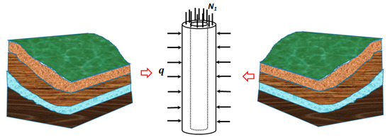
Figure 1.
Schematic diagram of stress acting on shaft wall.
For the reinforced concrete shaft wall, the ultimate bearing capacity of the shaft wall could be determined by the maximum compressive stress that a reinforced concrete composite structure could bear, and the limit equilibrium equation to calculate the ultimate bearing capacity of shaft wall N could be written as follows:
where N is the ultimate bearing capacity of the shaft wall, α is the stability factor of the reinforced concrete member (since the shaft wall is constrained by the earth pressure around, here α = 1), p is the axial bearing capacity of the concrete shaft wall under multi-directional stress, A is the cross-sectional area of the shaft wall (when the reinforcement ratio is greater than 3%, A can be replaced by , and is the total sectional area of the longitudinal reinforcement bars), and is the design value of reinforcement strength.
In the deep topsoil formation, the horizontal stress q acting on the shaft wall is
where q is the horizontal stress acting on the shaft wall, is the gravity density of water, and H is the cover depth.
In the present study, the shaft wall material is assumed to be continuous, homogeneous and linear elastic. The force acting on the shaft wall is analyzed with a plane strain model. Since the shaft wall is axisymmetric, the Lame solution when only external pressure is applied can be introduced during the calculation of shaft wall stress, and the shaft wall stress can be expressed as follows [27]:
where σr is the radial stress on the shaft wall, σφ is the tangential stress on the shaft wall, q is the external pressure acting on the shaft wall, r0 is the inner radius of the shaft, R is the outer radius of the shaft and r is the distance from the calculated point position to the center of the shaft section area. It is noted that positive denotes the compressive stress/force, while negative denotes the tensile stress/force, respectively.
The fractures on the shaft wall are mainly governed by the compression cracks based on the in situ analysis, and most shaft fractures are caused by local flake peeling on the inner surface of the shaft surface. Therefore, taking into account the stress on the inner surface of the shaft wall, Equation (3) could be simplified as:
Since the inner surface of the shaft wall is free, the shaft wall is in a bidirectional stress state, and the yield function of concrete under biaxial compression could be expressed as follows [28]:
where αs is the shear yield parameter and can be determined as , and , f1 and f2 represent the horizontal and vertical forces of concrete, respectively.
Based on the above, the following could be obtained:
where K is the strength enhancement factor when the concrete wall is under biaxial compression.
The ultimate bearing capacity of the shaft wall could be determined as follows:
3.2. Calculation of Operating Stress on Shaft Wall
The horizontal stress acting on the shaft wall is mainly caused by surrounding strata pressure. When the cover depth of the shaft is equal to 200 m, the horizontal ground stress could be calculated as 2.6 MPa. Substituting those values into Equation (4), then the tangential stress on the shaft wall could be obtained.
The vertical stress on the shaft wall mainly includes three parts: the dead weight of the shaft wall G, the gravity of the shaft tower N2 and the vertical additional stress τ (see Figure 2). The dead weight of the shaft wall contains the weight of concrete, steel bars and the equipment installed on the shaft wall. The arrangement of the tower foundation can be divided into two types: the arrangement of independent foundation around the shaft wall, and N2 is 0; installation of the tower directly on the shaft wall, and, in this pattern, N2 is the total weight of the tower, wellhead equipment and transport load. The vertical additional stress τ is mainly caused by the formation settlement.
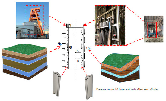
Figure 2.
Simplified model for stress analysis of “shaft-stratum-derrick” system.
Based on the above, the statics equilibrium relationship of the “shaft-stratum-derrick” system could be summarized as follows:
where γ is the dead weight of the shaft wall per unit length; τz is the shear stress on the shaft wall per unit length; D is the outer diameter the shaft; σz is the vertical stress of the borehole wall; and z is the distance between calculation position at the shaft wall to the earth surface.
Based on Hooke’s law and Equation (8), the following can be obtained:
The deformation of the deep soil layer changes from elastic to plastic after a certain depth is exceeded [23]. The relationship of shear stress between the soil layer and the shaft wall is as follows:
where Ks is the unit stiffness coefficient between the soil and the shaft wall; S is the settlement of the soil layer outside the range of the shaft wall influence area; V is the displacement of the shaft wall; c is cohesion of contact between the soil layer and the shaft wall; is the lateral pressure coefficient; is the angle of internal friction; and is the average effective weight of the soil layer.
Substituting Equation (9) into Equation (10), Equation (10a) can be written as follows:
Substituting Equation (9) into Equation (10), Equation (10b) can be written as follows:
The process of solving Equation (14) is as follows:
According to the above derivation, could be obtained as follows:
According to the displacement constraint, the stress constraint relation and the relationship between the external load and the stress on the shaft wall, a quantitative boundary constraint equation is proposed, and then Cn (n = 1, 2, 3, 4) is determined:
- (a)
- Assuming the bedrock is a rigid body, the bottom of the topsoil would not move with the settlement of the surrounding soil, and then Z = H, could be obtained.
- (b)
- Assuming that the shaft wall is a continuum medium model, the shaft wall at the interface between the elastic and plastic soil layer could conform to the displacement and stain the single value condition, then .
- (c)
- Vertical strain could not happen at the wellhead of the shaft wall, then .
- (d)
- The relative displacement between the soil and the shaft wall at the elastic–plastic interface is about 7 mm according to the experimental analysis, then .
Based on the above boundary conditions, Cn (n = 1, 2, 3, 4) could be deduced as follows:
Substituting Equation (21) into Equation (20), and based on Hooke’s law , the following results could be obtained:
where Zp is the solution of the cubic equation with one variable, Equation (23), as follows:
4. Ultimate Criterion of Shaft Wall
In order to study the failure mechanics of the concrete material, the calculation procedure of displacement and deformation is simplified, and the ultimate analysis based on the ideal elastoplastic model is selected in the present study.
In the limit analysis based on the ideal elastic–plastic model, the stress–strain curve entering the plastic state shows that the stress is constant and the strain increases infinitely. In the stage of plastic flow, if the material state is represented by stress, then the material yield criterion is consistent with the failure criterion. When the strain is used to represent the material state, the yield criterion is inconsistent with the failure criterion. When the material reaches the elastic limit strain, it is in the initial yield state, and the material is not damaged. With the development of plasticity, the material strain reaches its limit strain, and the material is damaged. Based on the above analysis, the ultimate strain value of shaft lining concrete could be analyzed through the ideal elastic–plastic theory. When the shaft lining strain reaches the ultimate strain at a certain point, the shaft lining failure can be judged. Therefore, the ultimate strain is taken as the ultimate criterion of shaft instability in deep topsoil.
Concrete is one frictional material that is typically used in civil engineering, and a certain relationship is proved to exist between compressive strain and shear strain. Under a small deformation, the strain of rock or rock-like materials could be divided into elastic strain and plastic strain, and the total strain is the sum of the elastic strain and the plastic strain. When the influence of intermediate principal stress is ignored, the relationship between elastic compressive strain and shear strain could meet the Mohr–Coulomb criterion as follows [29]:
where ; ; c is the cohesion force of the material; φ is the internal friction angle of the material; and E and v are the elastic modulus and Poisson’s ratio of the material, respectively.
When the material reaches the elastic limit state under a triaxial condition, according to the generalized Hooke’s law, the elastic limit principal strain satisfies:
where , and are the first, second and third elastic limit principal strains, respectively.
Substituting Equation (25) into Equation (24), the elastic limit strain of concrete can be obtained as follows:
In the deep topsoil stratum, the shaft wall structure mainly bears the axial stress caused by the formation compression, while the lateral and annular stresses are small; thus, the stress state of the shaft wall could be regarded as uniaxial. Under a uniaxial stress state, the elastic ultimate compressive strain can be simplified as follows:
Equation (26) is the elastic ultimate axial strain under a conventional triaxial condition, and Equation (28) is the elastic ultimate axial strain under a uniaxial condition. The strain on the shaft wall increases continuously until failure under the plastic condition. The relationship between compressive strain and shear strain in the total elastic–plastic strain could be expressed by taking polar coordinates on the deviant strain plane. The principal strain is related to the and on the deviant strain plane as follows:
where and are the shear strain and the Lode’s angle, respectively.
Substituting into Equation (31), the maximum shear strain can be obtained as follows:
where γf is the maximum shear strain.
Assumed that the shaft wall is isotropic material and Poisson’s ratio is constant, then and under a uniaxial stress state, and Equation (31) could be changed into:
The relationship between total elastic–plastic compressive strain and shear strain under a uniaxial stress state is described in Equation (33), which also satisfies the strain relation under an ultimate failure state. In addition, the ultimate shear strain of materials under a uniaxial stress state could be solved as followings:
Equation (34) is the calculation formula of ultimate shear strain; however, the ε2 needs to be obtained in the relationship between and . It is assumed that the total compressive strain and elastic strain of the material follows Equations (35)–(37):
where εf is the total compressive strain; εy is the elastic strain.
Based on the theoretical analysis of ultimate strain, the convergence of displacement at the key points is used as the failure criterion. The strain propagation process of concrete specimens with a dimension of 150 mm × 150 mm × 150 mm is reproduced by the finite difference method (FDM), as shown in Figure 3. The numerical model was constructed with 3375 elements and 4096 nodes. The concrete material was reproduced by the finite element mesh that followed the Mohr–Coulomb failure criterion. The left and right sides were free boundaries, the bottom boundary was fixed with no rotation, and a friction coefficient was applied to the top and bottom of the specimen.
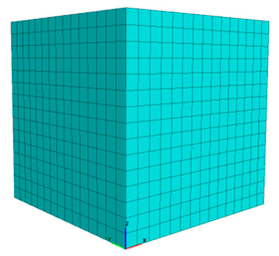
Figure 3.
Concrete cubic model reproduced by FEM.
A cutting plane 1-1, as shown in Figure 4, was selected to analyze the strain evolution procedure of the cubic concrete specimen in the FDM analysis, and the strain evolution process of this concrete specimen at this cutting plane is shown in Figure 5. The ultimate strain failure surface of concrete (C25) material presents as X-shaped. The failure initiates at the outer edge of the model and gradually extends towards inside, as shown in Figure 5. The failure mode of the concrete material gradually changes from point failure to coalescence failure, which is consistent with the results obtained by the uniaxial compression test in the laboratory. The maximum depth from the failure point to the earth surface is about 76.4 mm, and the maximum distance from the failure point to the model boundary is about 64.5 mm.
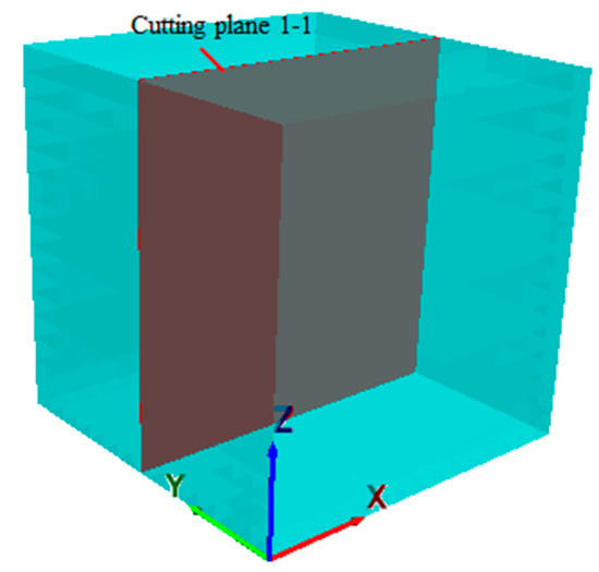
Figure 4.
Location of cutting plane.
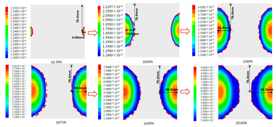
Figure 5.
Strain evolution procedure of shaft lining concrete under different stress conditions.
Using the same method, the χ value of concrete with different grades could be obtained, as shown in Table 1 [24].

Table 1.
The χ value of different-strength concrete tests.
5. A Case Study of Coal Mine Shaft Wall in Deep Topsoil Area
5.1. The Ultimate Stress on a Coal Mine Shaft Wall
The coal mine wall is a double-layer composite, and silt is filled between the inner and the outer wall (see Figure 6). Taking the auxiliary shaft as the object, the inner diameter of the auxiliary shaft wall is 7.5 m, while the outer diameter is 9.6 m. The inner wall concrete is layered by pouring. The upper layer is poured by C25 concrete, and the lower layer is poured by C35 concrete. The radius of reinforcement is 3.8 m, and the spacing of vertical reinforcement (B16) is 300 mm. According to the concrete strength design specification, the design axial compressive strength C25 is 11.9 MPa, the design axial compressive strength of C35 is 16.7 MPa, and the design value of secondary reinforcement strength is 300 MPa.
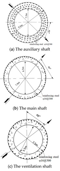
Figure 6.
The mine shaft profile.
Put these relevant parameters into Equation (7), then the calculation can be described as follows:
The sectional area of the shaft wall:
The sectional area of the longitudinal reinforcement:
The strength enhancement factor:
The ultimate bearing capacity of the shaft wall:
The ultimate bearing capacity of the main shaft and the ventilation shaft wall is tabulated in Table 2.
Table 2.
Stress acting on the shaft wall.
According to the reinforcement and concrete of the shaft wall, the weight of the coal mine shaft is determined as 0.0243 MN/m3. Since the mine shaft tower acts on the independent foundation, N2 = 0. The relevant parameters (see Table 3) are substituted into Equation (22), and the stress acting on the shaft could be calculated; the results are listed in Table 2.
Table 3.
Shaft parameters.
The ultimate bearing capacities of the auxiliary shaft, the main shaft and the ventilation shaft are 22.22 MPa, 22.07 MPa and 21.73 MPa, respectively. The stress near the interface between the bedrock and topsoil is selected as the representative value of shaft working stress according to the failure characteristics of the shaft wall. Since the working stress of the shaft wall is affected by the buried depth. The working stresses acting on the auxiliary shaft, the main shaft and the ventilation shaft are 31.45 MPa, 27.20 MPa and 39.92 MPa, respectively. Since the working stress is greater than the ultimate bearing capacity of the shaft wall, the shaft wall concrete would be damaged. This result is consistent with the actual situation.
5.2. Ultimate Strain of a Coal Mine Wall
Based on the principle of the rock and soil shear strength test, the direct shear test is combined with the uniaxial compression test, and the shear strength index test value, standard value and design value of the concrete are finally measured, as shown in Table 4 [25]. The cohesive force of the concrete is obtained by the direct shear experiment under a frictionless condition, and the friction angle of the concrete is given by the theoretical relationship between compressive stress and shear stress.
Table 4.
The shear strength of concrete.
Based on the structural analysis of the shaft wall in Section 5.1, the shear strength parameters of the concrete (C35) and the axial compressive strength of the shaft concrete are substituted into Equations (28)–(30) and Equations (35)–(37) to obtain the ultimate design strain value of the shaft wall, and the results are used as the reference value of the elastic and plastic ultimate strain of the shaft wall. By substituting the vertical stress into the ultimate strain solution formula, the ultimate strain value of the shaft wall in the coal mine is obtained. The specific results are shown in Table 5.
Table 5.
Limit strain of shaft wall concrete.
The designed ultimate compressive strain of the shaft wall concrete is calculated based on the frictionless shear test and the compression test, and the design values of the auxiliary shaft, the main shaft and the ventilation shaft are 1.468‰, 1.458‰ and 1.435‰, respectively. The designed ultimate shear strain is determined as 1.149‰, 1.041‰ and 1.124‰, respectively. Based on the ideal elastic–plastic theory, the ultimate strain near the interface between the bedrock and topsoil is selected as the representative ultimate strain value of the shaft wall according to the failure characteristics of the shaft wall. The ultimate compression strain of the auxiliary shaft, the main shaft and the ventilation shaft is 2.078‰, 1.800‰ and 2.638‰, respectively, and the ultimate shear strain values corresponding to those shafts are 1.626‰, 1.407‰ and 2.064‰, respectively. Since the ultimate strain of the shaft wall is greater than the design value, it can be concluded that the shaft wall concrete is in failure.
The ultimate state is the limit between the reliability and failure of a structure. The stability of the shaft wall could be evaluated based on the calculation of ultimate bearing capacity or ultimate strain of a large-diameter shaft in deep topsoil. When the critical value of the bearing capacity or strain is exceeded, the shaft wall is destroyed. In the ideal elastic–plastic analysis, the strain of the shaft wall concrete exhibit an increment, while the stress tends to be stable, which means that the strain increases when the shaft wall reaches its ultimate bearing capacity, until the ultimate strain is obtained. Thus, the instability criterion based on the ultimate strain analysis tends to be more accurate than those with the ultimate bearing capacity analysis.
5.3. Evolution Process of Ultimate Strain in a Coal Mine Shaft Wall
The ultimate strain is the lowest strain value for material failure. For a point, the ultimate strain indicates that the ideal plastic stress–strain curve reaches the failure condition. However, for a model on an engineering scale, although cracks appear and the material has reached local failure, due to the suppression of surrounding materials, a higher strain appears until the ultimate strain is connected. When an element in the material reaches the plastic ultimate strain, the element fails, which can be used as the basis for the local or point failure of the material. When the strain at each point on the penetrating failure surface is greater than the ultimate strain, the overall failure of the material occurs, and the penetrating of the ultimate strain zone is a necessary and sufficient condition for the overall failure of the material.
In the present study, the main shaft is selected to reproduce the failure process of the shaft wall based on the FDM, and the numerical model is shown in Figure 7. The numerical model was generated with 12,000 elements and 16,160 nodes, and the Mohr–Coulomb failure criterion was adopted in the numerical analysis. The bottom of the model was fixed with no rotation and displacement, and vertical additional force was applied at both the outer and upper surfaces of the shaft wall. The ultimate compressive strain and shear strain calculated by Equations (35)–(37) are 1.800‰ and 1.407‰, respectively, and those values are taken as the failure criteria. The failure region and evolution process of the shaft wall based on those criteria are shown in Figure 8 and Figure 9, and the strain on the shaft wall could be depicted only when those strain values are greater than the ultimate one. The shaft failure area is first initiated at the inner surface of the shaft wall, and with the increment in the calculation step, the failure area develops to the outer surface and coalesces with the outer wall, leading to the failure of the shaft wall.
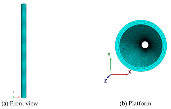
Figure 7.
Numerical model of the main shaft wall.
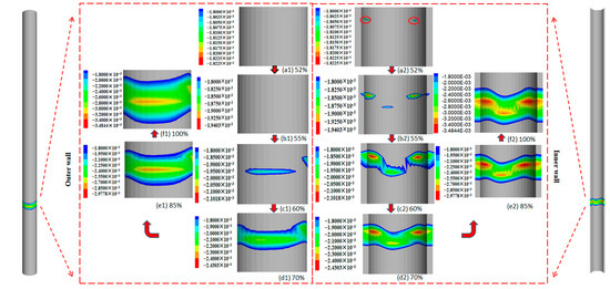
Figure 8.
Evolution process of the maximum ultimate compression strain on coal mine shaft wall concrete.
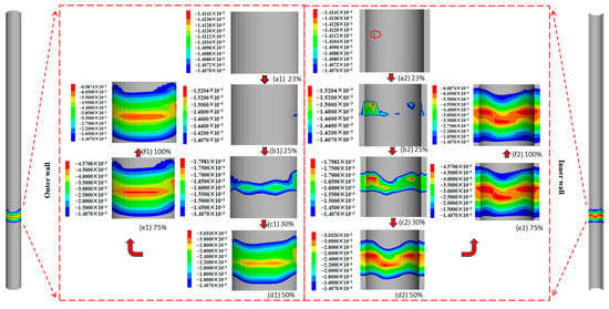
Figure 9.
Evolution process of maximum ultimate shear strain on coal mine shaft wall concrete.
Under multi-directional stress, a small ultimate compressive strain region is first initiated at the inner surface of the shaft wall 3 m above the bedrock (see Figure 8(a2)). With the increment in the calculation step, the ultimate compression strain region develops on both sides of the shaft wall outer surface, 1.5 m above the bedrock, as shown in Figure 8(c1). When the maximum value of the ultimate compressive strain reaches 70% of the maximum compressive strain, a coalescence area of ultimate compression strain occurs from the inner surface to the outer surface, as shown in Figure 8(d1,d2). When 85% of the maximum ultimate compressive strain is reached, the ultimate compressive strain region, as shown in Figure 8(e1,e2), with a height of 2.7 m, is formed. After the calculation is completed, the height of failure region is about 3 m (see Figure 8(f1,f2)), with an ultimate compression strain of 3.48‰.
The evolution process of ultimate shear strain on the shaft wall is shown in Figure 9. A small ultimate shear strain failure region first occurs at the inner surface of the shaft wall, 2.5 m above the bedrock, as shown in Figure 9(a2). With the increment in the calculation step, the ultimate shear strain region develops on both sides of the shaft wall outer and inner surfaces, as shown in Figure 9(c1,c2). When the maximum value of the ultimate shear strain reaches 50% of the maximum shear strain, a coalescence area of ultimate shear strain occurs from the inner surface to the outer surface, as shown in Figure 9(d1,d2), with a height of 4.6 m. When 75% of the maximum ultimate shear strain is reached, the ultimate shear strain region, as shown in Figure 9(e1,e2), with a height of 5.5 m, is formed. After the calculation is completed, the height of the failure region is about 6 m (see Figure 9(f1,f2)), with an ultimate shear strain of 6.09‰.
6. Discussion on Instability Criterion of a Large-Diameter Shaft
It is of great significance to find a reasonable and feasible method to identify the instability of a large-diameter shaft in deep topsoil for long-term service. At present, the commonly used instability criterion to judge whether the shaft is in the ultimate failure state is established based on field monitoring data (e.g., shaft strain, formation compression, aquifer water level, etc.) or on numerical simulation, compared with the empirical values of a previous study.
Several scholars used equilibrium and boundary conditions to solve the vertical stress of shaft walls in the unstable formation of deep topsoil. In addition, the stress near the interface between the bedrock and topsoil is selected as the representative value. If this stress at the interface is greater than the concrete strength of the shaft wall, it could be concluded that the shaft wall begins to crack. In the present study, the ultimate bearing capacity of the shaft wall under bidirectional stress is proposed, and the working stress of the shaft wall in the deep topsoil stratum is calculated. The ultimate strain of concrete shaft wall is given based on the ideal elastic–plastic model. According to the failure characteristics of shaft walls, the stress or strain near the interface between the bedrock and topsoil is selected as the representative value of the shaft wall. If the strain representative value is greater than the limit strain design value of the shaft walls or the representative stress value is greater than the limit bearing capacity of the shaft wall, it indicates that the shaft is unstable.
The failure of shaft walls is a gradual process. In the ultimate bearing capacity criterion, the shaft wall is regarded to be in failure when the peak strength of the shaft wall is obtained. However, the bearing capacity of the shaft wall is not lost when the ultimate bearing capacity is obtained, and the shaft wall can deform continuously until the ultimate strain is reached. Thus, when the representative value of stress is greater than the ultimate bearing capacity of the shaft wall, the shaft wall is damaged, while when the representative value of strain is greater than the ultimate strain design value, shaft instability occurs.
In the numerical ultimate analysis, there are three criteria to judge engineering instability and failure under a static state: (1) a plastic penetrating region is formed; (2) the displacement or stress does not converge; and (3) the displacement or strain of key points abruptly changes [30]. In practical application, the ultimate strain criterion can be introduced into numerical analysis to make the deformation and instability process of shaft walls more precise and intuitive.
7. Conclusions
In this study, we investigated the ultimate bearing capacity of shaft walls, operating stress on shaft walls, the ultimate stress criterion and the ultimate strain criterion of shaft instability according to the ultimate analysis method. We have the following conclusions.
(1) The shaft is located in a complex geological environment with deep topsoil, and the shaft wall bears different combinations of tensile and compressive stresses. According to the failure analysis of a large-diameter shaft in the deep topsoil formation, the strength failure criterion of shaft wall concrete under multi-axial force is introduced, and the ultimate bearing capacity of the shaft wall considering the bidirectional force state is proposed (Equation (7)). In addition, based on the analysis of shaft wall stress in the deep topsoil stratum, the calculation method of operating stress on the shaft wall is improved (Equation (22)).
(2) The concrete material is taken as the research object and the ideal elastoplastic ultimate analysis method is adopted. By introducing the shear strength and the compressive strength of shaft wall concrete, the design value of the elastic–plastic ultimate strain of the shaft wall is deduced (Equations (35)–(37)). The ultimate strain of the shaft wall is calculated by using the vertical stress results of the shaft wall. When the ultimate strain of the shaft wall is greater than the design value, it indicates that the shaft wall is damaged. It provides a theoretical basis for continuing the safe service and treatment of the shaft in a deep topsoil area. In addition, the ultimate strain criterion is more appropriate than the ultimate bearing capacity criterion.
(3) The effectiveness of the ultimate bearing capacity and ultimate strain criterion is verified by a case study of a coal mine. Under a bidirectional stress state, the ultimate bearing capacity of the auxiliary shaft, main shaft and ventilating shaft is 22.22 MPa, 22.07 Mpa and 21.73 Mpa, respectively. Based on the frictionless shear strength test and ultimate compressive strength test, the designed ultimate compressive strains of the auxiliary shaft, main shaft and ventilating shaft are 1.468‰, 1.458‰ and 1.435‰, respectively, and the design ultimate shear strains are 1.149‰, 1.041‰ and 1.124‰, respectively. The equivalent working stresses of the auxiliary shaft, main shaft and ventilating shaft at the soil–rock boundary are 31.45 MPa, 27.02 MPa and 39.92 MPa, respectively. The working ultimate compression strain is 2.078‰, 1.800‰ and 2.638‰, and the working ultimate shear strain is 1.626‰, 1.407‰ and 2.064‰, respectively. The working values are greater than the corresponding design values, which indicates that these shafts are in a state of instability. This result is consistent with the actual situation. Therefore, the limit strain criterion obtained based on ultimate analysis can describe the deformation and instability process of shafts in special strata with deep topsoil.
Author Contributions
Data curation, Z.L. and Y.C.; Formal analysis, X.W. and E.A.; Investigation, F.K.; Methodology, Z.L., Y.C., L.W. and E.A.; Project administration, X.W.; Resources, Q.C.; Supervision, Y.C., X.W., Q.C., L.W., F.K. and E.A.; Writing—original draft, Z.L. All authors have read and agreed to the published version of the manuscript.
Funding
We gratefully acknowledgement financial support from the National Natural Science Foundation of China under Grant No. 52179104, 42207201, 42272329 and 42272334. This work is also supported by the Co Fund of the Key Laboratory of Mining Disaster Prevention and Control, Shandong University of Science and Technology, No. MDPC202010.
Institutional Review Board Statement
Not applicable.
Informed Consent Statement
Not applicable.
Data Availability Statement
All the data, models or code generated or used in the present study are available from the corresponding author by request.
Conflicts of Interest
The authors declare that there is no conflict of interest that may affect the research reported in this paper.
References
- Cheng, H.; Cao, G.Y.; Yao, Z.S.; Rong, C.X.; Zhang, L.L. Tensile fracture mechanism of drilling shaft under the special engineering conditions of thick alluvium and thin bedrock. Meitan Xuebao 2021, 46, 100–111. (In Chinese) [Google Scholar]
- Xu, H.Y.; Gui, H.R.; S, B.K. Research on mechanism of failure and control measures of auxiliary shaft in Renlou Coal Mine. J. Suzhou Univ. 2016, 31, 112–119. (In Chinese) [Google Scholar]
- Roghanchi, P.; Kocsis, K.C. Quantifying the thermal damping effect in underground vertical shafts using the nonlinear autoregressive with external input (NARX) algorithm. Int. J. Min. Sci. Technol. 2019, 29, 255–262. [Google Scholar] [CrossRef]
- Corkum, A.G.; Damjanac, B.; Lam, T. Variation of horizontal in situ stress with depth for long-term performance evaluation of the Deep Geological Repository project access shaft. Int. J. Rock Mech. Min. Sci. 2018, 107, 75–85. [Google Scholar] [CrossRef]
- Walton, G.; Kim, E.; Sinha, S.; Sturgis, G.; Berberick, D. Investigation of shaft stability and anisotropic deformation in a deep shaft in Idaho, United States. Int. J. Rock Mech. Min. Sci. 2018, 105, 160–171. [Google Scholar] [CrossRef]
- Sun, X.M.; Li, G.; Zhao, C.W.; Liu, Y.Y.; Miao, C. Investigation of Deep Mine Shaft Stability in Alternating Hard and Soft Rock Strata Using Three-Dimensional Numerical Modeling. Processes 2019, 7, 2. [Google Scholar] [CrossRef]
- Chen, M.; Yang, S.Q.; Ranjith, P.G.; Zhang, Y.C. Cracking behavior of rock containing non-persistent joints with various joints inclinations. Theor. Appl. Fract. Mech. 2020, 109, 2–18. [Google Scholar] [CrossRef]
- Chen, M.; Zang, C.W.; Ding, Z.W.; Zhou, G.L.; Jiang, B.Y.; Zhang, G.C.; Zhang, C.P. Effects of confining pressure on deformation failure behavior of jointed rock. J. Cent. South Univ. 2022, 29, 1–15. [Google Scholar] [CrossRef]
- Liu, B.; Wang, Z.L.; Tang, S.J.; Sun, J.C.; Yao, B.; Sun, Y.D.; Wang, Y.Z. Mechanics analysis and repairment example of shaft collapse caused by the cross-border mining of nearby small coal mines. Meitan Xuebao 2018, 43, 61–70. (In Chinese) [Google Scholar]
- Tao, X.L.; Ma, J.R.; Zeng, W. Treatment effect investigation of underground continuous impervious curtain application in water-rich strata. Int. J. Min. Sci. Technol. 2015, 25, 975–981. [Google Scholar] [CrossRef]
- Ozturk, H.; Guler, E. A methodology for lining design of circular mine shafts in different rock masses. IJMST 2016, 26, 761–768. [Google Scholar] [CrossRef]
- Li, K.; Gao, Y.T.; Zhou, Y.; Li, J.W. Instability mechanism and reinforcement method of vertical shaft. J. Cent. South Univ. 2020, 51, 1068–1076. (In Chinese) [Google Scholar]
- Jiang, M.W.; Wang, X.; Liu, H.X.; Li, G.; Fan, Y.Y.; Liu, X.Q.; Wang, C.L. Optimization of drainage shaft wall is in complex geological environment. Arabian J. Geosci. 2022, 15, 111. [Google Scholar] [CrossRef]
- Yuan, Z.G.; Wang, H.T.; Hu, G.Z.; Liu, N.P.; Fan, X.G. Forecast model of GA-SVM for shaft-lining non-mining fracture. Meitan Xuebao 2011, 36, 393–397. (In Chinese) [Google Scholar]
- Li, J.J.; Hu, M.S.; Ding, E.J.; Kong, W.; Pan, D.M.; Chen, S. Multi-parameter numerical simulation of dynamic monitoring of rock deformation in deep mining. Int. J. Min. Sci. Technol. 2016, 26, 851–855. [Google Scholar] [CrossRef]
- Zhang, X.D.; Li, J.; Liu, J.S.; Peng, W.; Zhang, Z.C. Stability evaluation of soft rock supporting system of inclined shaft based on fuzzy comprehensive evaluation method. J. Liaoning Tech. Univ. 2018, 37, 476–481. (In Chinese) [Google Scholar]
- Xu, Y.C.; Gao, Y.B.; Li, J.H.; Gu, W.Z. Improvement and application of mine shaft safety evaluation system. Coal. Sci. Technol. 2016, 44, 95–101. (In Chinese) [Google Scholar]
- Pan, W.Q.; Zhang, L.M.; Cong, Y. Relationship Between Shaft Failure with Stress-Relief Groove and Groundwater Level in Thick Loose Strata. J. Jilin Univ. 2021, 51, 1578–1586. (In Chinese) [Google Scholar]
- Pleshko, M.S.; Pankratenko, A.N.; Pleshko, M.V.; Nasonov, A.A. Assessment of stress–strain behavior of shaft lining in bottomhole area during sinking by real-time monitoring and computer modeling data. Eurasian Min. 2021, 1, 25–30. [Google Scholar] [CrossRef]
- Singh, A.; Rao, K.S.; Ayothiraman, R. An analytical solution to shaft stability using Mogi-Coulomb failure criterion. J. Rock Mech. Geotech. Eng. 2019, 11, 1211–1230. [Google Scholar] [CrossRef]
- Liu, J.B.; Fu, J.X.; Wang, L.; Zhang, C. Three-Dimensional Model Construction and Shaft Stability Analysis for Filling Mining. Min. Metall. Eng. 2021, 41, 18–21. (In Chinese) [Google Scholar]
- Chen, C.; Zhou, J.; Zhou, T.; Yong, W.X. Evaluation of vertical shaft stability in underground mines: Comparison of three weight methods with uncertainty theory. Nat. Hazards 2021, 109, 1457–1479. [Google Scholar] [CrossRef]
- Li, W.P. Testing and theoretical studies on the interaction between soil and shaft wall during deep soil compression due to losing water. Chin. J. Geotech. Eng. 2000, 22, 475–480. (In Chinese) [Google Scholar]
- Abi, E.; Feng, X.T.; Zheng, Y.R.; Xin, J.P. Strain analysis and numerical analysis based on limit strain for geomaterials. Chin. J. Rock Mech. Eng. 2015, 34, 1552–1560. (In Chinese) [Google Scholar]
- Cong, Y.; Kong, L.; Zheng, Y.R.; Abi, E.; Wang, Z.Q. Experimental study on shear strength of concrete. Concrete 2015, 307, 40–45. (In Chinese) [Google Scholar]
- Liu, X.L. Study on Borehole Stress in Deep Topsoil Unstable Formation; China Coal Industry Publishing House: Beijing, China, 2004; pp. 5–13. (In Chinese) [Google Scholar]
- Xu, Z.L. A Concise Course in Elasticity; Higher Education Press: Beijing, China, 2016; pp. 73–75. (In Chinese) [Google Scholar]
- GB50010-2010; Code for Design of Architecture & Concrete Structures. China Architecture & Building Press: Beijing, China, 2010. (In Chinese)
- Zheng, Y.R.; Kong, L. Geotechnical Plastic Mechanics; China Architecture & Building Press: Beijing, China, 2019; pp. 14–22. (In Chinese) [Google Scholar]
- Zheng, Y.R. Development and application of numerical limit analysis for geological materials. Chin. J. Rock Mech. Eng. 2012, 31, 1297–1316. (In Chinese) [Google Scholar]


Publisher’s Note: MDPI stays neutral with regard to jurisdictional claims in published maps and institutional affiliations. |
© 2022 by the authors. Licensee MDPI, Basel, Switzerland. This article is an open access article distributed under the terms and conditions of the Creative Commons Attribution (CC BY) license (https://creativecommons.org/licenses/by/4.0/).