Highlights
- An integrated thermal and mechanical analysis of a liquid LBE tank.
- The effects of four filling medium parameters are evaluated.
- The viability of liquid LBE for solar TES tanks is evaluated.
Abstract
In order to evaluate the feasibility and performance of liquid lead-bismuth eutectic as the heat transfer fluid for thermocline heat storage tanks in solar power systems, we conducted an effect evaluation of filling medium parameters on the integrated operating and mechanical performances of a thermocline tank using liquid lead-bismuth eutectic using the computational fluid dynamics simulation method. Four parameters were evaluated: the porosity, thermal conductivity, specific heat capacity, and equivalent diameter of the filling medium. The results show that the liquid lead-bismuth eutectic tank operated stably. The total charging and total discharging durations were 5.7 h and 5.3 h, respectively, and the discharging efficiency was 91.94%. The effect evaluation results reveal that the discharging thermocline thickness of the liquid heavy metal tank can be decreased by increasing the specific heat capacity of the filling particles, or by decreasing the porosity, thermal conductivity, and equivalent diameter of the filling medium. The total discharging quantity of the tank increased from 2.19 × 10¹⁰ J to 3.34 × 10¹⁰ J when the specific heat capacity of the filling particles increased from 610.0 J/(kg∙K) to 1010.0 J/(kg∙K), while the other three filling medium parameters had no obvious effect on the total discharging quantity of the tank. The mechanical performance of the tank wall could be improved by decreasing any one of the four evaluated parameters of the filling medium. The results of this paper may serve as a reference for the design of actual liquid heavy metal heat storage tanks in solar power plants.
1. Introduction
Solar energy applications have continued to grow in recent years, and large-scale solar power mainly includes photovoltaic and CSP technologies. Because solar energy is naturally unstable and intermittent, energy storage devices are very important for SPSs. TES devices include dual-tank and single-tank structures. The former were used earlier, but they occupied a larger area and cost more. Therefore, researchers proposed the application of single heat storage tanks in SPSs using parabolic trough collectors. In contrast to the dual-tank structure, the single-tank structure could decrease the initial investment by 35%. Hence, the study of single-tank heat storage is very meaningful. Based on different solid heat storage materials, heat storage methods can be divided into the following three types: chemical, sensible, and latent heat storage technologies, where sensible heat storage is more mature and widely used. Potential HTFs for TES systems mainly include molten salts, heat transfer oils, liquid metals, and water (see Table 1) [1].

Table 1.
Different kinds of HTFs used in TES systems.
Researchers have conducted many studies on single-tank heat storage technologies. For instance, Yang and Garimella [2] employed a numerical simulation to systematically analyze the releasing behavior of the thermocline heat storage tank using quartzite as the filling medium and molten salt as the HTF. Their results indicate that the releasing efficiency can be increased with a smaller Reynolds number and a larger tank height. To study thermal ratcheting, Fernández-Torrijos et al. [3] developed a simplified two-phase model of a thermocline TES tank. The analysis results revealed that the model could be used to analyze the temperature changes in the filler material, molten salt, and tank wall. ELSihy et al. [4] conducted a study on the thermocline thickness variations of a molten salt heat storage tank using three different filling materials (quartzite rock, slag pebbles, and alumina ceramics). Their results indicate that slag pebbles as a filler material are more effective than quartzite rocks in TES tanks. Sun et al. [5] studied the heat storage characteristics of a tank using water as the HTF and PA/EG/CF phase change material as the encapsulation material. Their results show that increasing the Reynolds number, increasing the Stefan number, or reducing the dimensionless diameter can improve the average exergy storage rate. Zwierzchowski and Wolowicz [6] performed energy and exergy analyses of a large-scale cogeneration sensible heat storage tank in Poland and estimated the energy and exergy efficiencies.
LBE is a kind of liquid heavy metal (LHM) made of lead and bismuth [7]. It has many good physical properties [8], including a low melting point (423~473 K), a high boiling point (about 1943 K), low chemical activity, high thermal mobility, strong heat storage capacity, etc. It is one of the candidate HTF materials for CSP plants and TES systems. When the liquid LBE is used in a TES system, the TES system can have a wide operating temperature range with a relatively low lower temperature limit and a high upper temperature limit. However, the disadvantage of corrosion caused by high-temperature liquid LBE in the TES tank should also be considered.
Studies of liquid LBE used in TES systems are meaningful for the development of solar thermal power to a certain extent. Currently, LBE is mostly used in nuclear reactors [9], and experimental works on the use of liquid LBE in TES systems are rarely reported. Only a few simulation studies on liquid LBE-based TES systems have been reported. For instance, Pacio and Wetzel [10] carried out an evaluation of liquid LBE research paths for its use as HTF in CSP systems. The assessment results revealed the that the use of LBE in CSP systems is somewhat feasible. Laube et al. [11] conducted a thermodynamic analysis of a TES tank using different liquid metals. The feasibility and influence of the use of liquid LBE for TES tanks were studied and analyzed.
According to a literature review, though many thermal performance research works on TES tanks have been launched, most of these studies have focused on TES tanks using molten salts; numerical studies on TES tanks using liquid LBE are relatively few. Filling medium parameters can influence the operational behavior as well as the mechanical performance of TES tanks using liquid LBE, and related studies will be of value as a reference for the design of liquid LBE-based TES systems. This research gap should be addressed by undertaking studies on the effects of filling medium parameters on the integrated thermal and mechanical performances of TES tanks using liquid LBE.
Compared with previous research works, the novelty of this study is that the effects of filling medium parameters on the operating and mechanical performances of LBE-based TES tanks are evaluated based on the numerical simulation method, and four parameters (i.e., the porosity, thermal conductivity, specific heat capacity, and equivalent diameter of the filling medium) are investigated. The viability of LBE use for TES tanks and methods of improving the operational and mechanical performances of the TES tank are discussed. The results of this paper may provide a reference for the design of an actual LHM heat storage tank.
2. Material and Methods
2.1. Governing Equations
Figure 1 illustrates a liquid LBE thermocline heat storage tank that consists of three sections: the packing bed and the upper and lower distributors. The packing bed is composed of filling particles with an equivalent diameter of 60 mm. The vertical heights of the distributor, packing bed, and whole tank are Hdis (1 m), Hpacking (10 m), and Htank (14 m). The inner diameters of the inlet tube and LHM tank are Dtube (1 m) and Dtank (6 m). The thermocline thickness of the liquid LBE heat storage tank is dt. The wall of the liquid LBE tank is composed of three layers: fire brick, steel, and ceramic. Their densities are 2000 kg/m3, 8000 kg/m3, and 1000 kg/m3, their specific heat capacities are 1000 J/(kg∙K), 430 J/(kg∙K), and 1000 J/(kg∙K), and their thicknesses are 100 mm, 20 mm, and 50 mm respectively. The charging and discharging processes of the liquid LBE tank can also be seen in Figure 1.
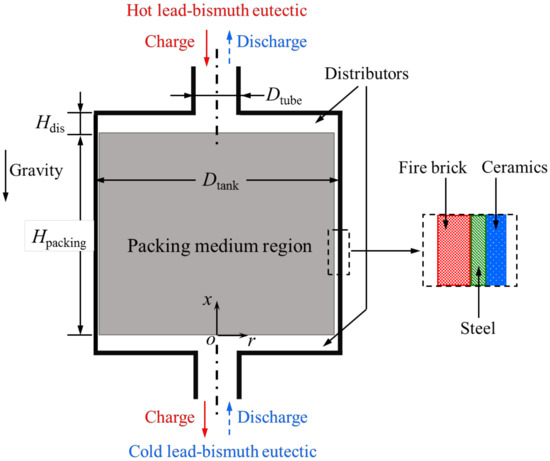
Figure 1.
Diagram of the liquid LBE thermocline tank.
For the liquid LBE tank model, some assumptions were adopted [12]:
- (a)
- The LBE flow and heat transfer were symmetrical about the axis.
- (b)
- The solid fillers in the packing region of the tank could be considered as a continuous, homogeneous, and isotropic porous medium.
- (c)
- The liquid LBE flow in the packing region was laminar and incompressible.
- (d)
- The properties of the filling particles in the packing region were constant.
For the liquid LBE, the governing equations were [13]:
where keff represents the effective heat conductivity of the combination of the liquid LBE and filling medium.
The energy equation for the solid fillers was [13]:
The heat conduction and heat balance equations for the wall of the liquid LBE tank were [13]:
where T1, T2, and T3 are the temperatures of the fire brick, steel, and ceramic layers and k1, k2, and k3 are the corresponding thermal conductivities.
The mixed boundary condition for the wall surfaces of the tank was [13]:
where Tw and εw are the temperature and emissivity of the ceramic surface and Tamb is the environment temperature. Figure 2 presents a flow diagram of the solutions of the relevant governing equations.
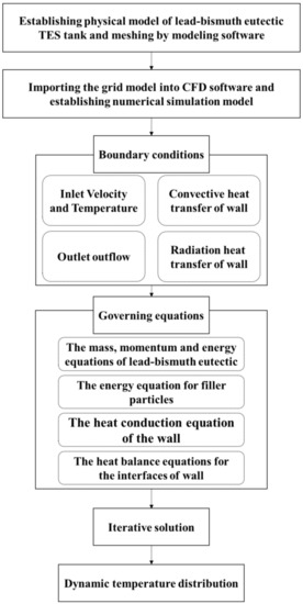
Figure 2.
Flow diagram of the governing equation solutions.
For the circumferential direction of the steel wall, the strain εL was [14]:
The MMS of the steel wall was [14]:
2.2. Numerical Model
In this study, the CFD simulation method was utilized to conduct the operation simulations for the LHM thermocline tank, and the commercial software used for the CFD simulations was Fluent. For the numerical model of the liquid LBE-based TES tank, the turbulent model was the standard k-ε model. A 2-D dual-precision solver and PISO algorithm were employed. Gravity was taken into account, as can be seen in Figure 1. There was no inner heat source in the liquid LBE tank. For the outer top and side surfaces of the TES tank, the mixed boundary condition, which considers both convective and radiation heat losses (see Equation (8)), was selected. The bottom surface temperature of the tank was set to be constant. According to the mesh sensitivity analysis results, the total mesh number of the numerical model was about 1.2 × 10⁶.
The expressions of the thermophysical properties of the liquid LBE were [15]:
Based on the experimental results of a relevant study [16], the applicability of the numerical model of the liquid LBE thermocline tank was validated. According to the literature, the height and inner diameter of the experimental prototype were 5.9 m and 1.5 m. The HTF in the experimental facility was molten salt consisting of NaNO3 and KNO3. As presented in Figure 3, the results reveal a relatively acceptable agreement between the test and simulation results.
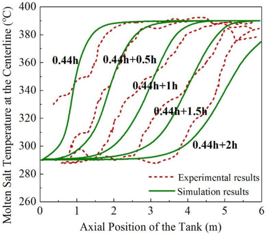
Figure 3.
Validation results of the numerical model.
3. Results
3.1. Operation Performance
This section evaluates and presents the operation performance of the liquid LBE thermocline tank. For the initial parameters for the simulation, the inlet flow rate uin was 0.000278 m/s. The initial cold temperature Tc of the liquid LBE was 566 K. The initial hot temperature Th of liquid LBE was 723 K. The filling medium porosity εfiller was 0.2. The equivalent diameter of the solid fillers was 0.06 m. The thermal conductivity kfiller, specific heat capacity CP,filler, and density ρfiller of the solid fillers were 5.8 W/(m∙K), 810 J/(kg∙K), and 2550 kg/m3, respectively. The equivalent diameter Dfiller of filling particles was 60 mm. The ambient temperature Tamb was 298 K.
The charging and discharging processes of the liquid LBE heat storage tank were simulated. Figure 4 shows the liquid LBE temperature distributions of the tank during the discharging process. It can be seen that the thermocline was effectively formed and kept during the whole process. It could go up and through the tank stably, which means the liquid LBE tank had good operating stability. According to the simulation results, the total charging and total discharging durations were 5.7 h and 5.3 h, respectively, and the discharging efficiency was 91.94%, which is close to that reported in the previous literature (about 92%) [11]. The total discharging quantity of the tank was 2.75 × 10¹⁰ J (about 7.64 MWh). These results can provide reference values for the heat release capacity and operation parameter designs of actual TES tanks using liquid LBE.
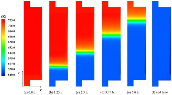
Figure 4.
Liquid LBE temperature distribution variations of the TES tank in the discharging process.
3.2. Effect Evaluation Results of Filling Medium Parameters
3.2.1. Effects of Porosity of the Filling Medium
The effect evaluation results of the porosity εfiller of the filling medium on the discharging and mechanical performances of the liquid LBE heat storage tank are provided in Figure 5, Figure 6 and Figure 7. The circles in the figures indicate the ordinates corresponding to the curves surrounded by them. As is shown in Figure 5 and Figure 6, the porosity of the filling medium had no obvious influence on the total discharging duration tdischarge or the maximum discharging power Pmax of the tank, but did affect the thermocline thickness of the tank. The thermocline thickness of the tank during the discharging process increased as the porosity of the filling medium increased. This agrees with the results reported in the previous literature [13].
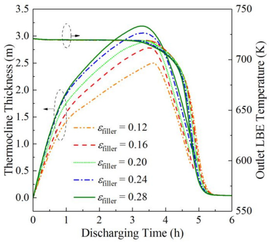
Figure 5.
Thermocline thickness and outlet HTF temperature variations at different filling medium porosities during discharging processes.
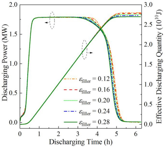
Figure 6.
Discharging power and total discharging quantity variations at different filling medium porosities.
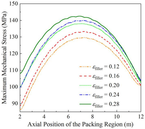
Figure 7.
Axial MMS distribution variations at different filling medium porosities.
The effect of the porosity of the filling medium on the total discharging quantity Qrelease of the tank was also relatively small. This is because when the porosity of the filling medium increased, the total mass of the liquid LBE in the packing region also increased. The heat carried by the added liquid LBE compensated to a large extent for the heat lost due to the reduction in solid filling materials.
Figure 7 presents the axial MMS distribution variations of the liquid LBE tank at different filling medium porosities. Figure 7 shows that as the porosity of the filling medium increased from 0.12 to 0.28, the peak MMS increased from 129.7 MPa to 142.5 MPa. This is partly because when the filling medium porosity increases, the mass of liquid LBE in the packing region increased, thus leading to a bigger temperature difference between the maximum and minimum temperatures of the steel wall. Thus, it can be concluded that by reducing the porosity of the filling medium, the thermocline thickness during the discharging process and the peak MMS can both be decreased.
3.2.2. Effects of the Thermal Conductivity of the Filling Medium
This section presents the effect evaluation results of the thermal conductivity kfiller of the filling particles on the discharging and mechanical behaviors of the liquid LBE thermocline tank. The relevant results are shown in Figure 8, Figure 9 and Figure 10.
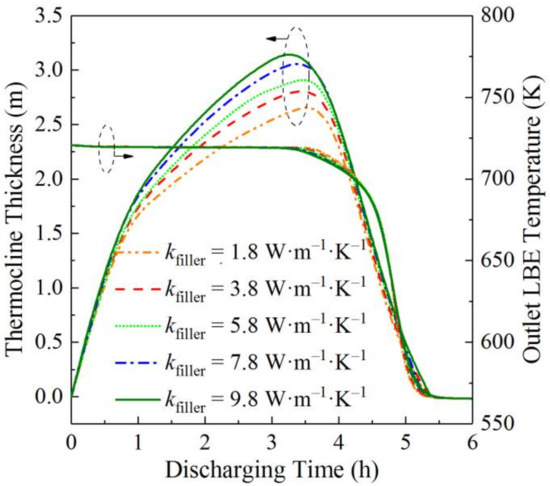
Figure 8.
Thermocline thickness and outlet HTF temperature variations at different thermal conductivities of the filling particles during discharging processes.
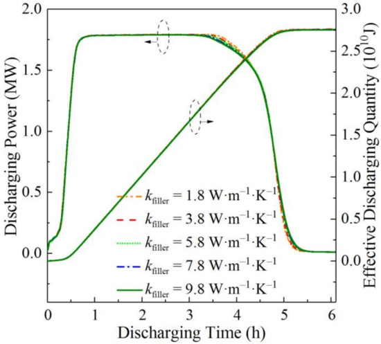
Figure 9.
Discharging power and total discharging quantity variations at different thermal conductivities of the filling particles.
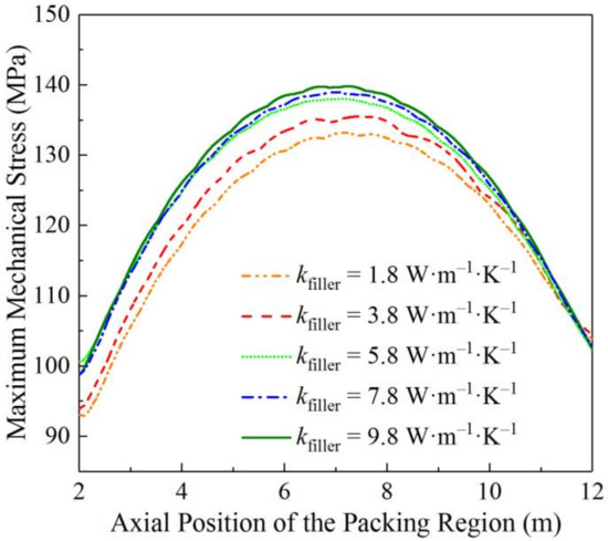
Figure 10.
Axial MMS distribution variations at different thermal conductivities of the filling particles.
According to Figure 8, the thermal conductivity of the filling particles essentially had no effects on the total discharging duration or the outlet LBE temperature, though it had an obvious impact on the thermocline thickness of the liquid LBE tank during discharging processes. As the thermal conductivity of the filling particles increased, the maximum thermocline thickness of the liquid LBE tank increased. This was due to an improvement in the heat transfer between the liquid LBE and the filling medium caused by an increase in the thermal conductivity of the filling particles. This conclusion agrees with that reported in the previous literature [12]. When the thermal conductivity of the filling particles was 9.8 W/(m∙K), the maximum thermocline thickness of the tank was 3.3 m. The results of Figure 9 reveal that the thermal conductivity of filling particles had little effect on either the maximum discharging power or the total discharging quantity of the liquid LBE tank.
The axial MMS distribution variations of the liquid LBE tank at different thermal conductivities of the filling particles are shown in Figure 10. It can be seen that the peak MMS increased as the thermal conductivity of the filling particles increased. This is because a lower particle thermal conductivity will weaken the heat transfer between the liquid LBE and the filling particles, as well as the heat transfer between the tank wall and the packing bed. This reduces the maximum temperature of the steel wall during the operating cycle, resulting in a smaller MMS. This was also reported in the relevant study [13]. When the thermal conductivity of the filling particles was 9.8 W/(m∙K), the peak MMS of the tank wall was 139.8 MPa. Therefore, it was demonstrated that by decreasing the thermal conductivity of the filling particles, the thermocline thickness during the discharging process and the peak MMS can both be decreased.
3.2.3. Effects of the Specific Heat Capacity of the Filling Medium
The effect evaluation results of the specific heat capacity CP,filler of the filling particles on the discharging behavior of the liquid LBE tank are shown in Figure 11 and Figure 12. According to the two figures, the specific heat capacity of the filling particles had an obvious effect on the discharging process. As the specific heat capacity of the filling particles increased from 610.0 J/(kg∙K) to 1010.0 J/(kg∙K), the total discharging duration increased from 4.5 h to 6.5 h, the maximum thermocline thickness decreased from 3.4 m to 2.8 m, the total discharging quantity of the tank increased from 2.19 × 10¹⁰ J to 3.34 × 10¹⁰ J, while the maximum discharging power of the tank was basically unchanged. The maximum thermocline thickness decreased with the increase in the specific heat capacity of the filling particles because the temperature increase caused by the same heat quantity reduced when the specific heat capacity of the filling particles increased. The total discharging quantity increased with the increase in the specific heat capacity of the filling particles because for the same temperature variation the heat release of the filling medium with the higher specific heat capacity was larger.
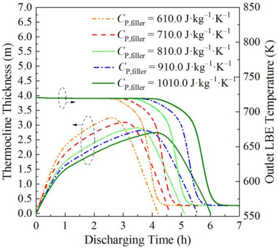
Figure 11.
Thermocline thickness and outlet HTF temperature variations at different specific heat capacities of the filling particles during discharging processes.
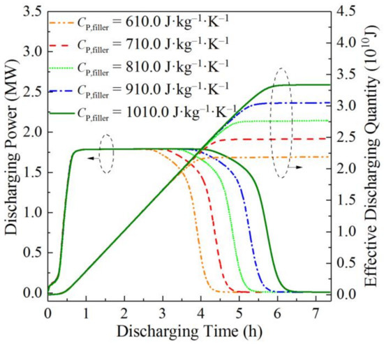
Figure 12.
Discharging power and total discharging quantity variations at different specific heat capacities of the filling particles.
Figure 13 presents the axial MMS distributions of the liquid LBE tank at different specific heat capacities of the filling particles. The results reveal that the peak MMS increased as the specific heat capacity of the filling particles increased. When the specific heat capacity of the filling particles was 1010.0 J/(kg∙K), the peak MMS was 145.6 MPa. Hence, by increasing the specific heat capacity of the filling particles, the thermocline thickness during the discharging process can be reduced and the total discharging duration and total discharging quantity of the tank can both be increased, but the peak MMS will also be increased.
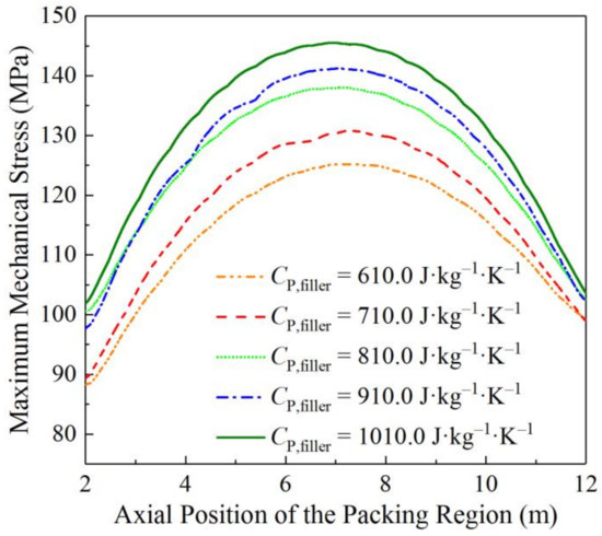
Figure 13.
Axial MMS distribution variations at different specific heat capacities of the filling particles.
3.2.4. Effects of the Equivalent Diameter of the Filling Medium
This section presents the effect evaluation results of the equivalent diameter Dfiller of the filling particles on the performances of the liquid LBE thermocline heat storage tank. Figure 14 shows the variations of thermocline thickness and the outlet LBE temperature of the tank at different equivalent diameters of the filling particles. The results reveal that the equivalent diameter of filling particles had a very small effect on the total discharging duration, and that the thermocline thickness of the tank during the discharging process increased when the equivalent diameter of the filling particles increased. This is because increasing the equivalent diameter of the filling particles can lead to the temperature difference between the liquid LBE and the solid particle surfaces increasing, as well as that within the solid particles, which contributes to a faster thermocline expansion and thus results in a thicker thermocline layer. This conclusion is similar to that reported in [17]. When the equivalent diameter of the filling particles increased to 0.10 m, the maximum thermocline thickness of the tank was 3.1 m. According to Figure 15, the effects of the equivalent diameter of the filling particles on the maximum discharging power and total discharging quantity of the tank were both very small. These results are similar to those of the effect evaluations of the porosity and thermal conductivity of the filling particles on the discharging performance.
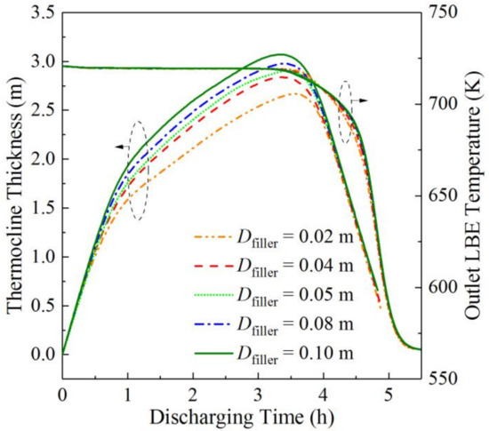
Figure 14.
Thermocline thickness and outlet HTF temperature variations at different equivalent diameters of the filling particles during discharging processes.
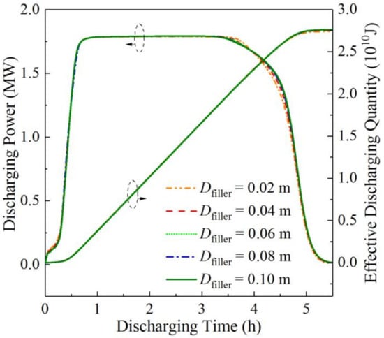
Figure 15.
Discharging power and total discharging quantity variations at different equivalent diameters of the filling particles.
Figure 16 shows the axial MMS distributions of the liquid LBE thermocline tank at different equivalent diameters of the filling particles. The results show that as the equivalent diameter of the filling particles increased from 0.02 m to 0.10 m, the peak MMS increased from 129.4 MPa to 148.7 MPa. The reason for this influence law is similar to that of the filling medium porosity. Thus, it can be concluded that by decreasing the equivalent diameter of the filling particles, the thermocline thickness during the discharging process and the peak MMS can be both reduced.
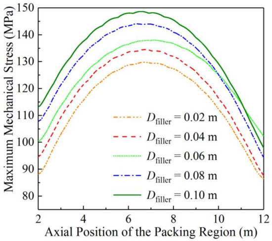
Figure 16.
Axial MMS distribution variations at different equivalent diameters of the filling particles.
4. Conclusions
Liquid lead-bismuth eutectic is a potential heat transfer fluid material for thermal energy storage tanks. This study used the computational fluid dynamics simulation method to evaluate the effects of filling medium parameters on the integrated operation and mechanical performances of a thermocline tank using lead-bismuth eutectic and a filling medium. Four filling medium parameters were evaluated: porosity, thermal conductivity, specific heat capacity, and equivalent diameter of the filling medium. The simulation results showed that the liquid heavy metal tank could achieve stable operation, indicating the technical feasibility of the use of lead-bismuth eutectic in thermal energy storage systems. The total charging and total discharging durations were 5.7 h and 5.3 h, respectively, the discharging efficiency was 91.94%, and the total discharging quantity was 2.75 × 10¹⁰ J. The effect evaluation results demonstrate that the thermocline thickness during the discharging process can be reduced by increasing the specific heat capacity of the filling particles, or by decreasing the porosity, thermal conductivity, and equivalent diameter of the filling medium. The total discharging quantity of the tank can be increased by increasing the specific heat capacity of the filling particles. As the specific heat capacity of the filling particles increased from 610.0 J/(kg∙K) to 1010.0 J/(kg∙K), the total discharging quantity of the tank increases from 2.19 × 10¹⁰ J to 3.34 × 10¹⁰ J. The maximum mechanical stress of the tank can be reduced by decreasing any one of the four evaluated parameters of the filling medium. The analysis results of this study can enrich the research of thermal energy storage tanks using liquid metals and provide a reference for the selection of filling media and the structural safety design of steel walls for thermal energy storage tanks.
There are still some limitations in this study. For instance, the packing region of the heat storage tank was simplified so as to be a continuous porous medium. A more detailed filling medium structure should be considered for the tank in the future research. In addition, this paper lacks practical experimental study results. An experimental study based on a small liquid lead-bismuth eutectic tank prototype will be a meaningful next step, and may provide test data for the validation of the numerical model of the tank as well as for a comparison with simulation results.
Author Contributions
Writing—original draft, G.W., Writing—review & editing, T.W. All authors have read and agreed to the published version of the manuscript.
Funding
The authors appreciate the support of the Natural Science Foundation of Jilin Province of China (Grant No. 20210101081JC).
Institutional Review Board Statement
Not applicable.
Informed Consent Statement
Not applicable.
Data Availability Statement
The data presented in this study are available on request from the corresponding author.
Conflicts of Interest
The authors declared that there is no actual or potential conflict of interest including any financial, personal or other relationships with other people or organizations within three years of beginning the submitted work that could inappropriately influence, or be perceived to influence, their work.
Nomenclatures
| CP | specific heat capacity | J/(kg∙K) |
| dt | thermocline thickness | m |
| D | diameter | m |
| E | elasticity modulus | Pa |
| F | inertial coefficient of the porous medium | |
| H | height | m |
| hinter | interstitial heat transfer coefficient | W/(m2∙K) |
| K | intrinsic permeability of the porous medium | m2 |
| k | thermal conductivity | W/(m∙K) |
| L | thickness of the wall layer | m |
| mass flow rate | kg/s | |
| Q | heat quantity | J |
| T | temperature | K |
| t | time | h |
| u | velocity | m/s |
| Greek symbols | ||
| α | thermal expansion coefficient | K−1 |
| εfiller | porosity of packed medium | |
| εm | mechanical strain | |
| εt | thermal strain | |
| εw | emissivity of the tank wall | |
| η | efficiency | |
| μ | viscosity | kg/(m∙s) |
| ρ | density | kg/m3 |
| σmax | maximum mechanical stress | Pa |
| Subscripts | ||
| c | cold | |
| dis | distributor | |
| discharge | discharge process | |
| eff | effective | |
| filler | filling particle | |
| fluid | heat transfer fluid | |
| h | hot | |
| in | inlet | |
| m | mechanical | |
| max | maximum | |
| min | minimum | |
| t | thermal | |
| w | tank wall | |
| Abbreviations | ||
| CF | carbon fiber | |
| CFD | computational fluid dynamics | |
| CSP | concentrated solar thermal power | |
| EG | expanded graphite | |
| HTF | heat transfer fluid | |
| LBE | lead-bismuth eutectic | |
| LHM | liquid heavy metal | |
| MMS | maximum mechanical stress | |
| PA | palmitic acid | |
| SPS | solar power system | |
| TES | thermal energy storage | |
References
- Wang, G.; Pang, S.; Jiang, T. A brief review of liquid heat transfer materials used in concentrated solar power systems and thermal energy storage devices of concentrated solar power systems. Eng. Rep. 2022, 2022, e12576. [Google Scholar] [CrossRef]
- Yang, Z.; Garimella, S.V. Molten-salt thermal energy storage in thermoclines under different environmental boundary conditions. Appl. Energy 2010, 87, 3322–3329. [Google Scholar] [CrossRef]
- Fernández-Torrijos, M.; Sobrino, C.; Almendros-Ibáñez, J. Simplified model of a dual-media molten-salt thermocline tank with a multiple layer wall. Sol. Energy 2017, 151, 146–161. [Google Scholar] [CrossRef]
- EL Sihy, E.S.; Liao, Z.; Xu, C.; Du, X. Dynamic characteristics of solid packed-bed thermocline tank using molten-salt as a heat transfer fluid. Int. J. Heat Mass Transf. 2021, 165, 120677. [Google Scholar] [CrossRef]
- Sun, B.; Liu, Z.; Ji, X.; Gao, L.; Che, D. Thermal energy storage characteristics of packed bed encapsulating spherical capsules with composite phase change materials. Appl. Therm. Eng. 2021, 201, 117659. [Google Scholar] [CrossRef]
- Zwierzchowski, R.; Wołowicz, M. Energy and Exergy Analysis of Sensible Thermal Energy Storage—Hot Water Tank for a Large CHP Plant in Poland. Energies 2020, 13, 4842. [Google Scholar] [CrossRef]
- Grötzbach, G. Challenges in low-Prandtl number heat transfer simulation and modelling. Nucl. Eng. Des. 2013, 264, 41–55. [Google Scholar] [CrossRef]
- Thiele, R.; Anglart, H. Numerical modeling of forced-convection heat transfer to lead–bismuth eutectic flowing in vertical annuli. Nucl. Eng. Des. 2013, 254, 111–119. [Google Scholar] [CrossRef]
- Wang, G. A Review of Recent Numerical and Experimental Research Progress on CDA Safety Analysis of LBE-/Lead-cooled Fast Reactors. Ann. Nucl. Energy 2017, 110, 1139–1147. [Google Scholar] [CrossRef]
- Pacio, J.; Wetzel, T. Assessment of liquid metal technology status and research paths for their use as efficient heat transfer fluids in solar central receiver systems. Sol. Energy 2013, 93, 11–22. [Google Scholar] [CrossRef]
- Laube, T.; Marocco, L.; Niedermeier, K.; Pacio, J.; Wetzel, T. Thermodynamic Analysis of High-Temperature Energy Storage Concepts Based on Liquid Metal Technology. Energy Technol. 2019, 8, 1900908. [Google Scholar] [CrossRef]
- Xu, C.; Wang, Z.; He, Y.; Li, X.; Bai, F. Sensitivity analysis of the numerical study on the thermal performance of a packed-bed molten salt thermocline thermal storage system. Appl. Energy 2012, 92, 65–75. [Google Scholar] [CrossRef]
- Wang, G.; Yu, S.; Niu, S.; Chen, Z.; Hu, P. A comprehensive parametric study on integrated thermal and mechanical performances of mol-ten-salt-based thermocline tank. Appl. Therm. Eng. 2020, 170, 115010. [Google Scholar] [CrossRef]
- Flueckiger, S.; Yang, Z.; Garimella, S.V. An integrated thermal and mechanical investigation of molten-salt thermocline energy storage. Appl. Energy 2011, 88, 2098–2105. [Google Scholar] [CrossRef]
- OECD; Nuclear Energy Agency. Handbook on Lead-Bismuth Eutectic Alloy and Lead Properties, Materials Compatibility, Thermalhydraulics and Technologies; Organisation for Economic Co-Operation and Development: Paris, France, 2015; Available online: https://publications.jrc.ec.europa.eu/repository/handle/JRC100764 (accessed on 23 August 2022).
- Pacheco, J.E.; Showalter, S.K.; Kolb, W.J. Development of a molten-salt thermocline thermal storage system for parabolic trough plants. J. Sol. Energy Eng. 2002, 124, 153–159. [Google Scholar] [CrossRef]
- Xu, C.; Li, X.; Wang, Z.; He, Y.; Bai, F. Effects of solid particle properties on the thermal performance of a packed-bed molten-salt thermocline thermal storage system. Appl. Therm. Eng. 2013, 57, 69–80. [Google Scholar] [CrossRef]
Publisher’s Note: MDPI stays neutral with regard to jurisdictional claims in published maps and institutional affiliations. |
© 2022 by the authors. Licensee MDPI, Basel, Switzerland. This article is an open access article distributed under the terms and conditions of the Creative Commons Attribution (CC BY) license (https://creativecommons.org/licenses/by/4.0/).