Article

A Study on the Interaction Behavior between an Earth-Rock Dam and a New-Typed Polymer Anti-Seepage Wall

School of Water Conservancy and Civil Engineering, Zhengzhou University, Zhengzhou 450002, China
*
Author to whom correspondence should be addressed.
Sustainability 2022, 14(21), 14357; https://doi.org/10.3390/su142114357
Submission received: 10 September 2022 / Revised: 26 October 2022 / Accepted: 29 October 2022 / Published: 2 November 2022

Abstract

:
Polymer anti-seepage wall has been gradually applied in earth-rock dam reinforcement projects as a new seepage control technique. However, due to all-pervasive properties of the new materials and root-like connection between the materials and soils, the interface characteristics between the polymer wall and the earth-rock dam, as well as the interaction behavior of both, are complex and still not clear, which obstruct studying coordination mechanism of dam and wall under earthquake. Therefore, the interface characteristics and interaction behavior of dam and wall were studied in the article. Firstly, the dynamic shear stress-displacement, shear stiffness and damping ratio of the interface between polymer and soil were investigated by ring shear test. In addition, the viscoelastic constitutive model of polymer materials were researched by dynamic mechanical analysis (DMA) test. Based on tests results, a finite element model of earth-rock dam with polymer wall was established, including a non-linear simulation interface element and viscoelastic polymer constitutive model. Next, the validity of the simulation model was verified based on dynamic centrifuge test results. Then, the interaction behavior and seismic response of the dam with polymer wall were explored by using the verified model. The research results provide a scientific basis for the development and application of new-typed polymer anti-seepage wall in reinforcement engineering.

1. Introduction

Most earth-rock dams in worldwide range are currently plagued by problems, such as long operating periods and insufficient maintenance. As a result, serious hidden dangers such as liquefaction, instability and damage are easy to occur under seismic action [1,2,3,4,5]. As a new impermeable and reinforced technology, polymer anti-seepage wall, has been gradually applied in dam reinforcement engineering [6,7,8,9].
The new-typed polymer materials are produced by the reaction between polyols and isocyanate under high-pressure injection. They have the advantages of being environmentally friendly, lightweight, and durable. In addition, they also possess early strength properties and are different from conventional cement-based grouting materials, such as small disturbance on structure (static press in construction), earthquake and crack resistance behavior (compatible with soils), convenient construction equipment (only 2.4 m width of equipment) and low cost (saving 30% of time and cost). Therefore, they are widely used in seepage prevention, infrastructure reinforcement, and as support materials in infrastructure engineering projects [10,11,12,13,14,15] (Figure 1).
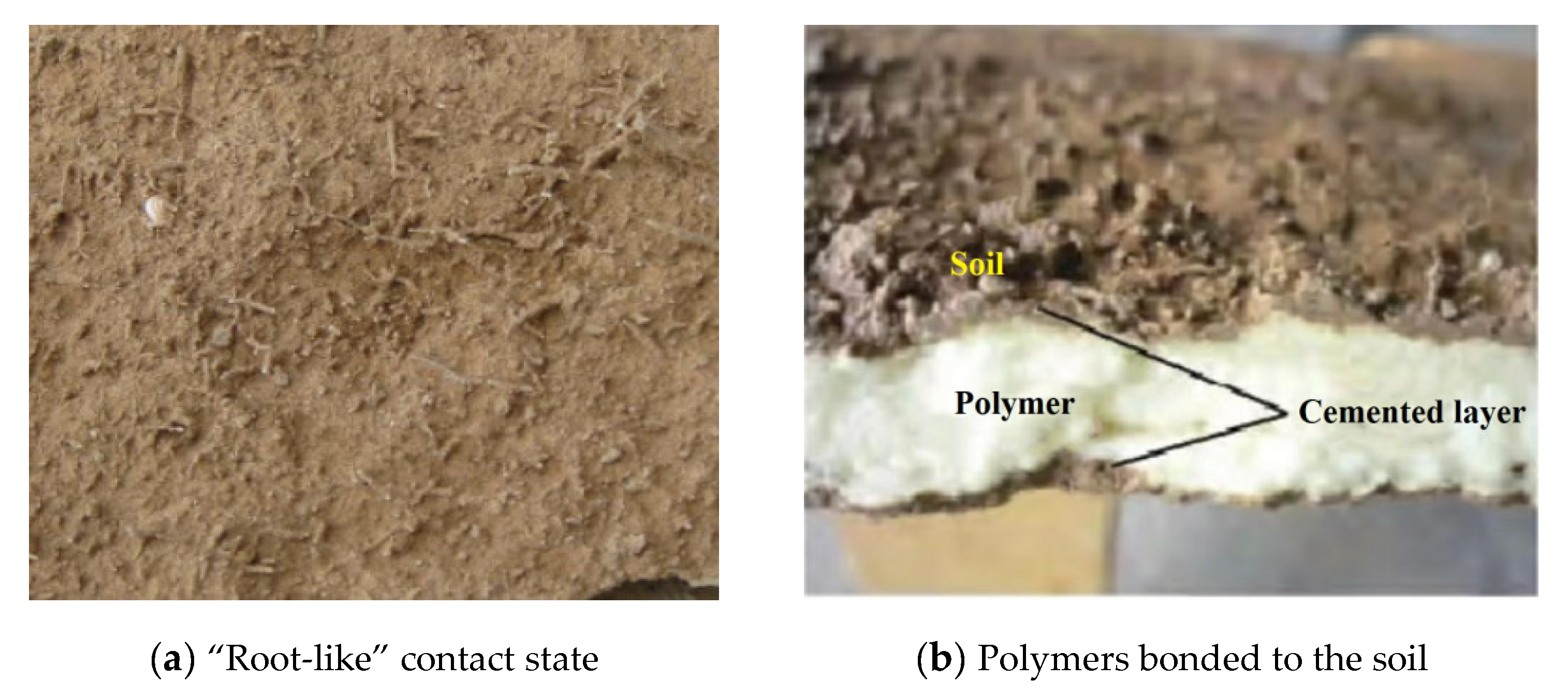
However, due to the expansion and bonding properties of the polymer material, it will form a “root-like” contact connection with soils (as shown in Figure 2), which makes the interface characteristics more complex [16]. Additionally, the addition of a polymer wall in dam changes the dynamic nature of the dam, such as self-oscillation period, self-oscillation frequency, and other characteristics which furthermore affects the seismic safety of earth-rock dam [17]. Therefore, the mechanical properties of the interface and the interaction laws between the polymer wall and the earth-rock dam are important in seismic analysis for the structure.
The experimental study is an important method for the study of the mechanical properties of the interface and the interaction laws. Uesugi and Kishida [18] conducted shear tests on the sand-steel interface and found the interface shear failure law. Zhu et al. [19] conducted ring shear tests on the soil-concrete interface and revealed the shear strength properties of the interface. Based on the research results of shear tests, the interface simulation element method has been redeveloped due to its ability of accurately simulating the interface mechanical properties. Toki et al. [20] firstly applied the Goodman element to the dynamic interaction model of wall-dam and studied the interaction behavior. Gao et al. [21] proposed a friction contact element and solved the problem of large difference in stiffness on both sides of the interface. Qi et al. [22] developed the nonlinear interface element of wall-dam, which can reflect the change law of dynamic interface characteristics.
With the research results of interface characteristics, the interaction behavior and seismic response of earth-rock dams with anti-seepage wall were also studied by scholars at home and abroad. Zhao et al. [23] systematically introduced the theory of dynamic infinite element and transient infinite element, which is of great significance to the development of the study of wall-dam interaction. Schenck et al. [24] analyzed the seismic response of wall-dam by boundary element method. Liu et al. [25] used the finite element method to discuss the interaction behavior between the wall and dam, and analyzed the seismic response of the wall-dam.
In conclusion, interface properties are important for studying the interaction law of different structure under earthquake, which can lay the foundation of the whole structure seismic stability analysis. In this paper, the interface characteristics between polymer and soil was investigated by ring shear test and the viscoelastic constitutive model of polymer materials was researched by DMA test. Based on the tests results, a finite element model of an earth-rock dam with a polymer wall was established. Then, the validity of the simulation model was verified by dynamic centrifugal test and the interaction behavior and seismic response of the dam with polymer wall were explored by using verified model.

2. Materials and Methods

2.1. Experimental Materials

2.1.1. Polymer Samples

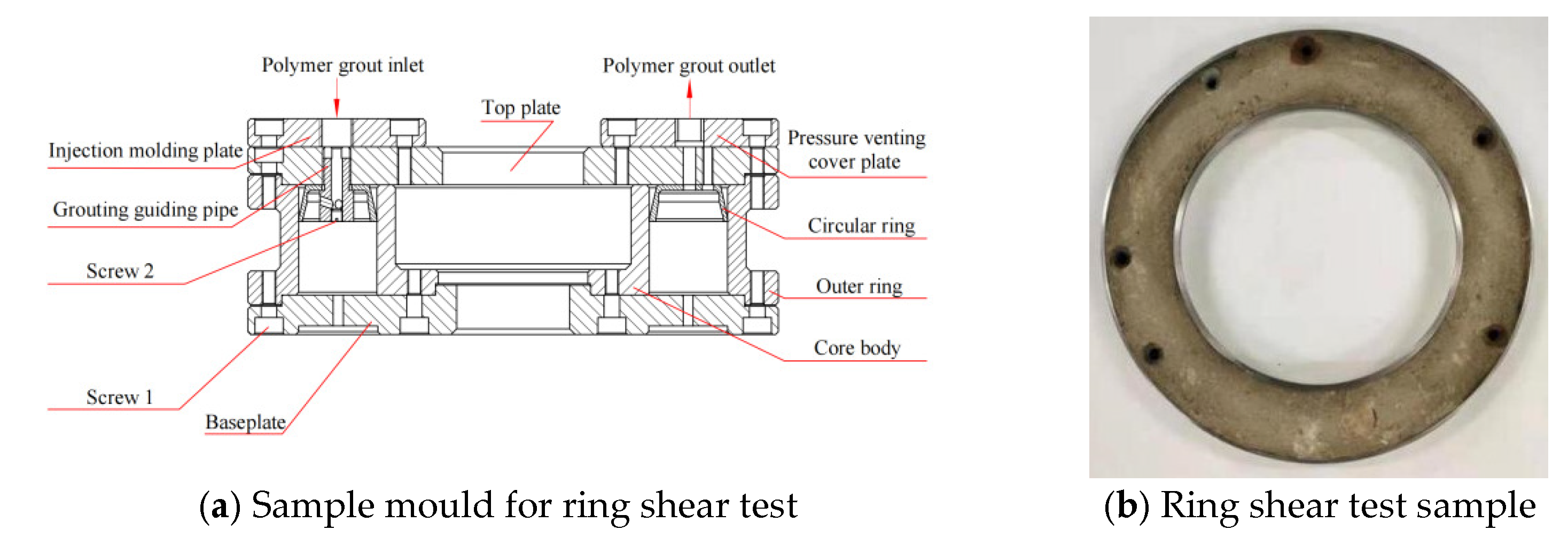
The manufacturing process of the ring shear test sample is as follows. Owing to the fluidity and expansibility of the polymer materials and considering the “root-like” contact state between the polymer and the soil, a mould was specially designed for forming the materials, as shown in Figure 3a. Firstly, the soil sample was placed in the core, the mold was assembled and fastened subsequently. Then, the polymer slurry was inject into the mould from the grouting inlet. When the polymer slurry overflows from the slurry outlet, the grouting is ended. Finally, the samples were taken out of the mould after 30 min. The finished sample is shown in Figure 3b.
The manufacturing process of DMA test sample is as follows. According to the experimental requirements, the mold consists of two steel plates and four asbestos plates, and the asbestos plate is used to control the thickness of polymer. Before grouting, a certain amount of lubricant was applied to the inner wall firstly, then the mold was assembled and the bolts were tightened. Finally, the two-component slurry was injected into the mold, and the polymer density was controlled by grouting volume. After 30 min, the samples were taken out and cut into rectangular samples with dimensions (L × W × T) of 50 mm × 13 mm × 2 mm, as shown in Figure 4b.
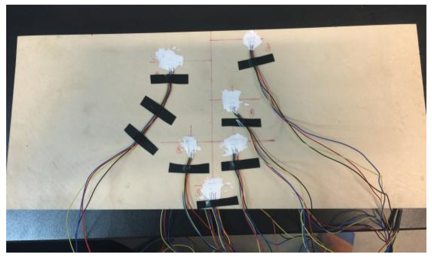
The manufacturing process of dynamic centrifuge test samples is in a similar way as DMA test samples. After the injection of polymer slurry, the samples were taken out with dimensions (L × W × T) of 400 mm × 170 mm × 2 mm, and the strain gauges were attached to the sample surface (Figure 5).
The physical parameters of the polymer materials used for the three tests are shown in Table 1.

2.1.2. Soil Samples

In this paper, silty clay is selected as the dam material for ring shear test and dynamic centrifugal test. Its physical parameters are shown in Table 2.

2.2. Experimental Test Methods

2.2.1. Ring Shear Test

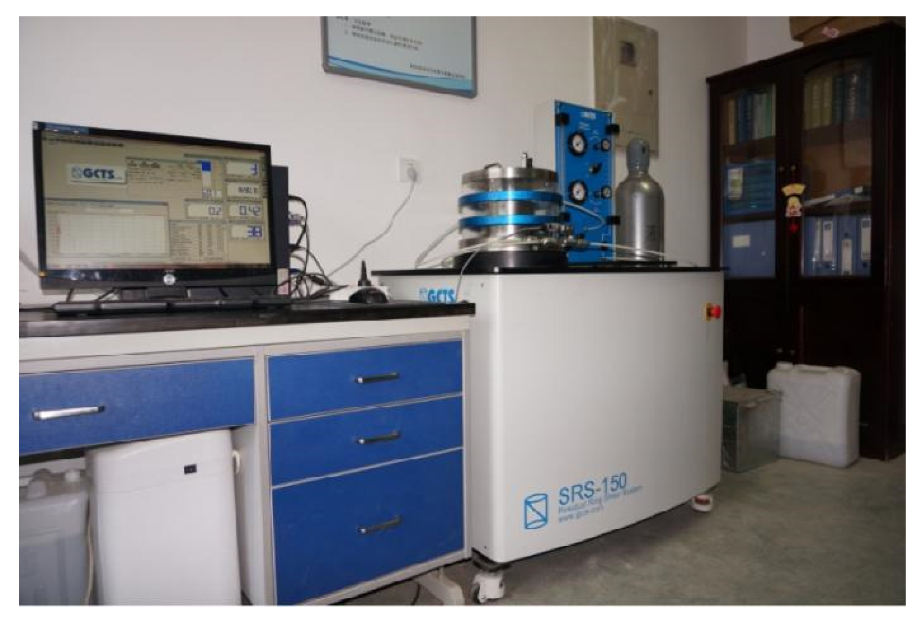
In order to study the effects of polymer density, cyclic amplitude and vertical stress on the dynamic properties of the polymer-soil interface, the ring shear test of the polymer-soil interface was conducted. Furthermore, the test was carried out by using the SRS-150 dynamic cyclic shear instrument (Figure 6). In the ring shear test, cyclic shear mode were adopted to simulate the dynamic load, and according to the pre-test results, three cyclic amplitudes (0.5 mm, 1.0 mm and 1.5 mm) and four vertical stresses (100 kPa, 200 kPa, 300 kPa and 400 kPa) were selected in this study. The test scheme is as presented in Table 3.

2.2.2. DMA Test

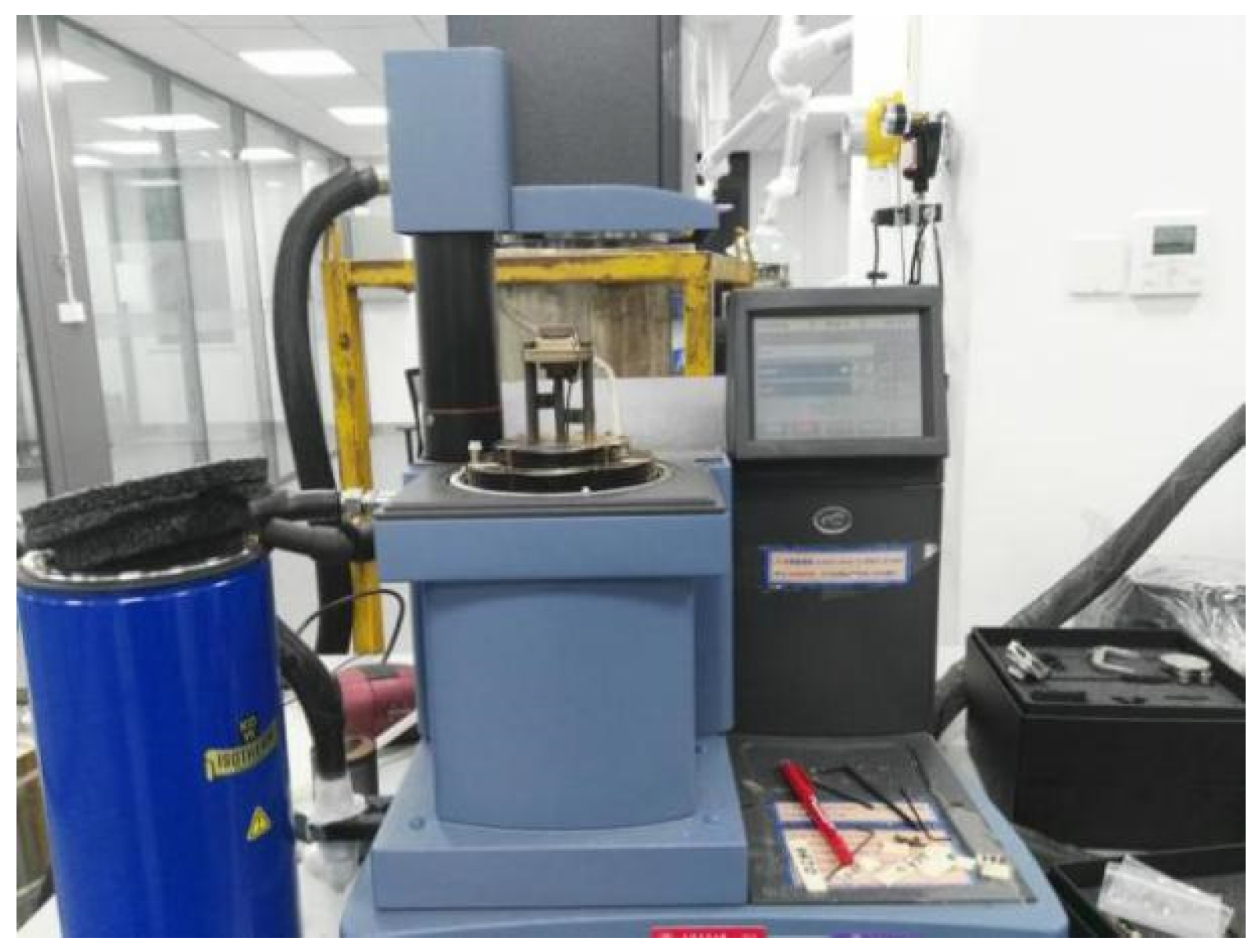
In order to characterize the dynamic viscoelastic properties of polymer materials and provide the constitutive model parameters of the polymer anti-seepage wall in finite element model, it is necessary to conduct the DMA test. In addition, the DMAQ800 dynamic thermal-mechanical analysis instrument (Figure 7) was used in the test. In the DMA test, five temperatures were selected (−50 °C, −25 °C, 0 °C, 25 °C and 50 °C) to simulate environmental temperature. Under comprehensive consideration of time and accuracy, the data from frequency scanning was extracted for every 2 Hz in this study. The test scheme is as presented in Table 4. For more details, one can refer to ref. [26].

2.2.3. Dynamic Centrifuge Test

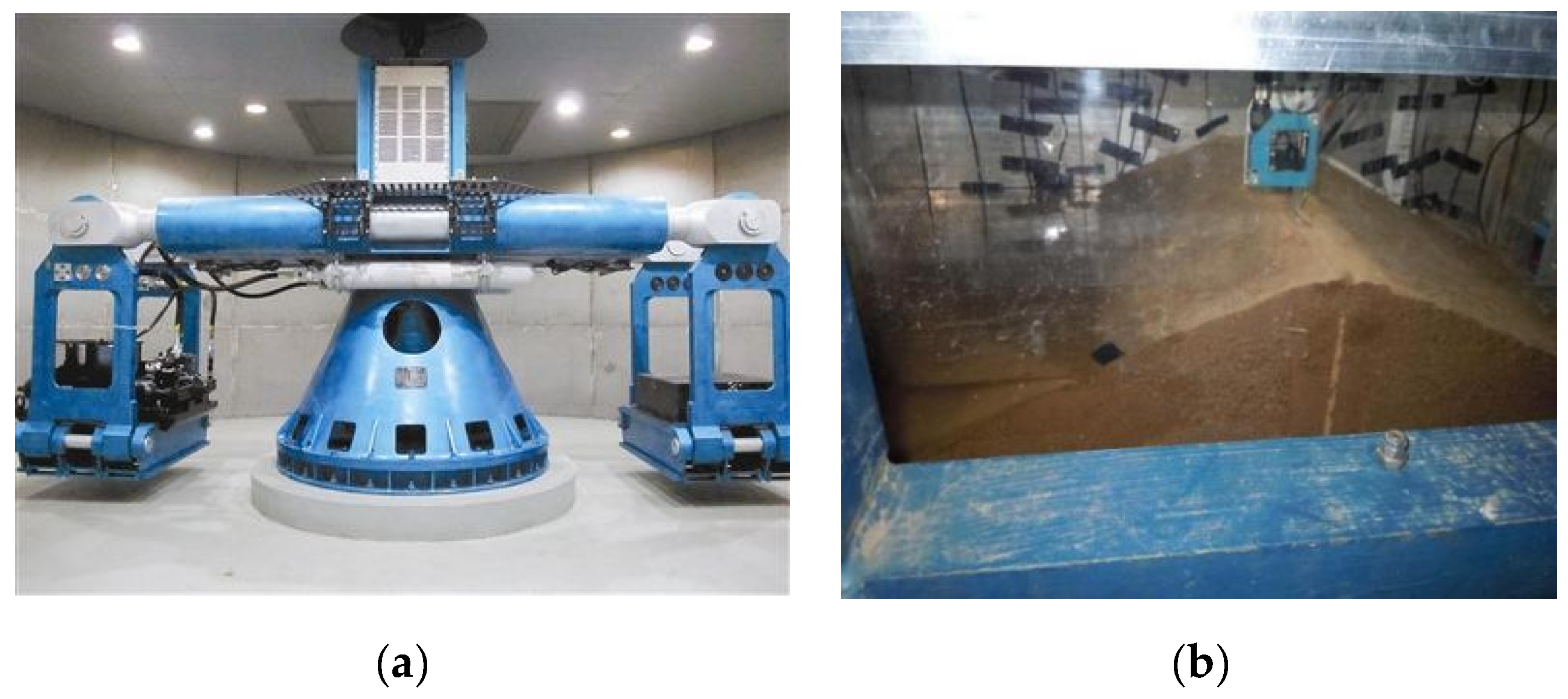
In order to study the seismic response of wall-dam and provide the validation of finite element simulation model, centrifuge shaking table test on the earth-rock dam with polymer wall [7] was conducted (Figure 8). The dynamic centrifuge model test was carried out with ZJU-400 geotechnical centrifuge and ZJU hydraulic servo shaking table equipment. In the dynamic centrifuge test, the geometry was scaled to 1/100 and El-Centro wave was inputted with four amplitudes of 0.05 g, 0.1 g, 0.2 g, and 0.4 g, respectively. The test scheme is as presented in Table 5. For more details, one can refer to ref. [27].

2.3. Finite Element Method (FEM)

2.3.1. Finite Element Simulation Model

(1)
Establishment of numerical model
The prototype of the numerical model is the earth-rock dam of Jiulong reservoir in Xinyang City, Henan Province, China. The dam has leakage due to its long service life, so the polymer anti-seepage wall was constructed at the dam axis for seepage prevention and reinforcement (Figure 9).
The model is divided into three parts: impervious dam foundation, homogeneous dam body and polymer anti-seepage wall. The dam foundation is 15 m high and 290 m long. The dam body is 15 m high, and the lower part is 90 m wide, the upper part is 5.6 m wide. Additionally, the polymer wall is 17 m high, 2 m deep into the dam foundation, 0.5 m away from the dam axis, and 0.02 m thick. Furthermore, the non-linear interface element was set between the polymer wall and the earth-rock dam.
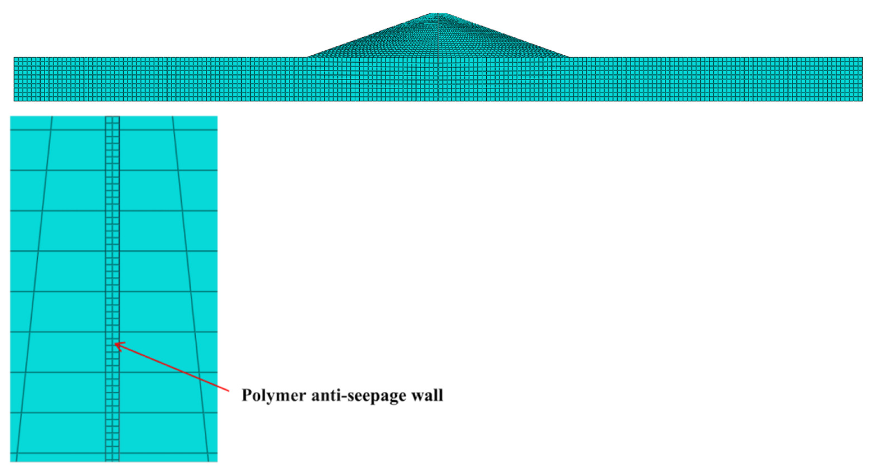
Based on the geometric model, CPE4 plane strain element were used in finite element mesh division, and the model was divided into 3639 elements (Figure 10). It should be noted that, in order to identify the difference between wall and dam, the mesh density of polymer wall is higher than that of earth-rock dam.
(2)
Selection of constitutive model
The equivalent linear viscoelastic constitutive model [28] was selected for dynamic simulation of the dam. The model can simulate the dynamic characteristics of earth-rock dam by considering the variation of damping ratio with strain. In addition, the calculation formula of the dynamic shear modulus G and the damping ratio λ obtained from the model are shown in Equations (1) and (2). According to the ring shear test results, the constitutive model parameters of earth-rock dam can be obtained, as shown in Table 6.
G = G max 1 + γ / γ r
λ = λ max γ / γ r 1 + γ / γ r
where γr is the reference shear strain; γ is the dynamic shear strain.
In addition, a viscoelastic constitutive model of new-type polymer materials was established and applied for the polymer anti-seepage wall, the constitutive model and relevant parameters of polymer wall was mentioned in following Section 2.3.3 and Section 3.2.1.
(3)
Setting of boundary conditions
The upper boundary of the model was set as the free boundary, and the other surrounding and lower boundaries were using viscoelastic artificial boundaries. The viscoelastic artificial boundary is an artificial boundary condition established based on the attenuated scattering wave expression to simulate the elastic recovery and viscous dissipation effects, whose expression is [29]:
σ j ( r b , t ) = ρ C j u ˙ j ( r b , t ) K j u j ( r b , t )
The physical meaning of the above equation is that a spring with a stiffness coefficient Kj connected to a damper with a damping coefficient of Cj, which is placed on the artificial boundary j point with a distance of rb from the point source.
And the damping coefficient Cj and stiffness coefficient of Kj are shown as follows [27]:
Tangential boundary
K j T = a T G R , C j T = ρ c s
Normal boundary
K j N = a N G R , C j N = ρ c P
where KjT, KjN are tangential and normal stiffness of spring, respectively. R is the distance from point source to artificial boundary point. cs, cp are the velocity of S wave and P wave, respectively. G is shear modulus of medium and ρ is the density. αT, αN are tangential and normal viscoelastic artificial boundary parameters, and the parameters take the values of 1.2 and 0.65, respectively.
(4)
Inputting of seismic wave
Seismic wave produces stress and resistance to overcome spring damper system at artificial boundary nodes, which are defined as equivalent force [30]. Therefore ground motion input can be realized by enforcing equivalent force at artificial boundary. The equivalent force expression is as follows:
m l u ¨ l i T + n j c l i n j + δ l n δ i j A l C l i u ˙ n j T + n j k l i n j + δ l n δ i j A l K l i u n j T = f l i F + A l K l i u l i F + C l i u ˙ l i F
where Klj and Clj are additional stiffness coefficient and damping coefficient in the direction of j at the boundary node l, respectively. u l j F ( t ) is the free field for original continuous medium. δln, δij are Delta function and viscoelastic boundary works only when l = n and i = j.
The El-Centro wave was selected as the seismic wave, and the SV wave was emitted vertically upward from the bottom of the dam with a duration of 20 s. Four seismic conditions of 0.05 g, 0.1 g, 0.2 g and 0.4 g were used for the calculations.

2.3.2. Non-Linear Interface Element

From the above analysis, the non-linear interface element can reasonably simulate the non-linear states, such as bonding, embedding, sliding and cracking. According to the early ring shear test results, the stress-strain curve of the interface between the polymer wall and the earth-rock dam conforms to the hyperbolic relationship [31,32,33].
Therefore, the non-linear hyperbolic model proposed by Clough and Duncan [34] was used to represent the stress-strain relationship for nonlinear interface element, where the asymptotic value of the hyperbola is ( C f σ y ) / R , and the tangential stiffnesses kx′ and normal stiffnesses ky′ are expressed in quadratic parabolic form, as shown in Equations (7) and (8).
k x = k x 0 1 1 cos α R τ x ( C f σ y ) 2
k y = k y 0 1 1 sin α R τ y ( C f σ y ) 2
where kx′0 and ky′0 are the initial tangential stiffness and initial normal stiffness of interface, respectively; C is the cohesive force; f is the friction coefficient; α is the friction angle of the shear surface.
According to the ring shear test results, the shear stiffness and damping ratio were used to simulate the dynamic characteristics of the wall-dam interface, so the dynamic constitutive model of the interface is as follows:
K = K max 1 + K max R f u σ n tan δ
where Kmax is the shear modulus; σn is the vertical stress; Rf is the interface failure ratio; δ is the interface friction angle; u is the shear displacement.
Based on the above derivation and calculation, the non-linear interface element can be used for the analysis of interface characteristics, and the running steps are shown in Figure 11.

2.3.3. Viscoelastic Constitutive Model

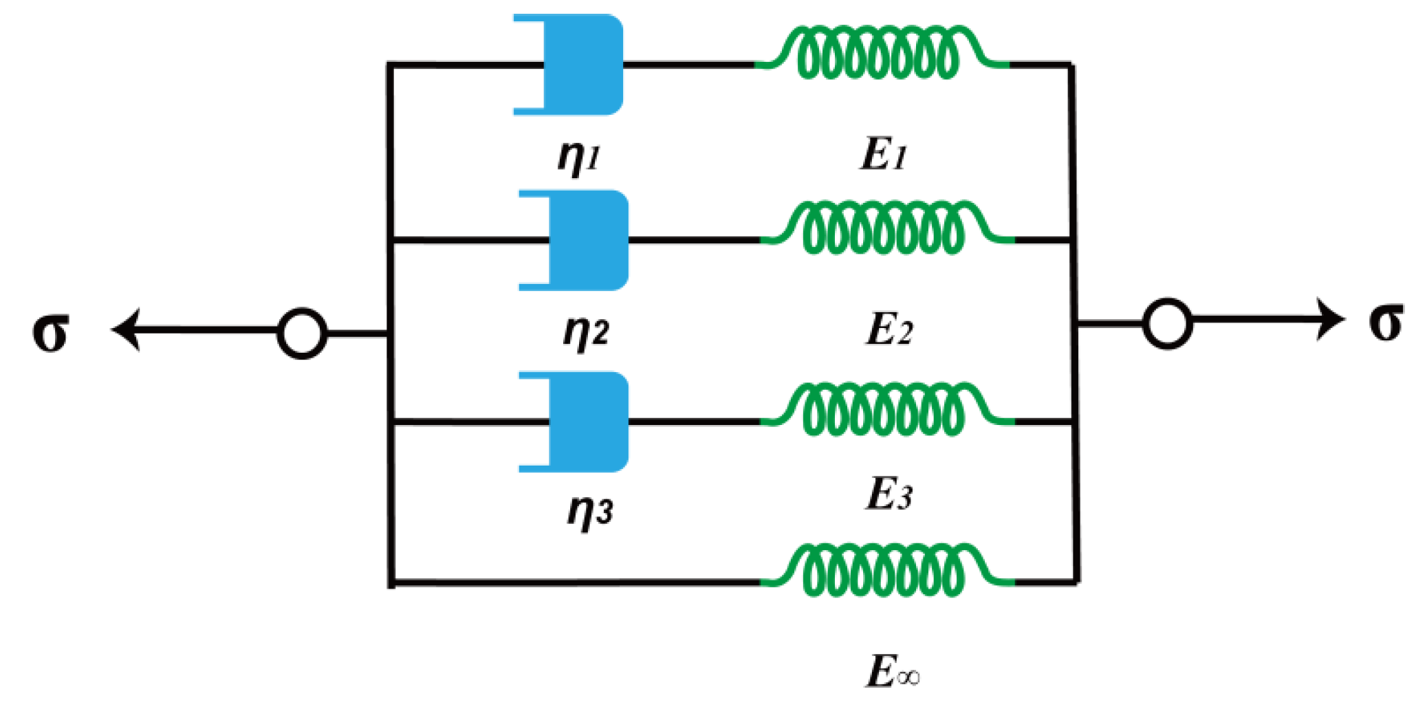
Since polymer materials have dynamic viscoelastic properties, the constitutive model of polymer wall needs to be discussed. Owing to the feasibility of parameter acquisition and direct application in structure analysis, the generalized Maxwell model was adopted to derive the viscoelastic constitutive relationship for polymer materials [35].
The generalized Maxwell model is composed of any number of Maxwell models in parallel, and each Maxwell model is composed with a Hooke spring and a Newton dashpot in series. Its modulus is Ei, viscosity is ηi, relaxation time τi = ηi/Ei, as shown in Figure 12. Related studies show that the fourth-order model (i.e., n = 4) has high efficiency, small error and convenient parameter acquisition [36]. Therefore, the viscoelastic constitutive model in this paper is of the fourth order, and its constitutive equations after expansion are as follows:
E = E + E g 1 + g 2 + g 3 + g 4 g 1 τ 1 2 ω 2 1 + τ 1 2 ω 2 + g 2 τ 2 2 ω 2 1 + τ 2 2 ω 2 + g 3 τ 3 2 ω 2 1 + τ 3 2 ω 2 + g 4 τ 4 2 ω 2 1 + τ 4 2 ω 2
E = E g 1 + g 2 + g 3 + g 4 g 1 τ 1 ω 1 + τ 1 2 ω 2 + g 2 τ 2 ω 1 + τ 2 2 ω 2 + g 3 τ 3 ω 1 + τ 3 2 ω 2 + g 4 τ 4 ω 1 + τ 4 2 ω 2
where E′ is storage modulus, E″ is loss modulus, E is quasi static modulus, gi is dimensionless modulus parameters, τi is relaxation time, ω is frequency.
Based on the DMA test results, the model parameters were obtained by fitting the experimental data and the generalized Maxwell model, see Section 3.2.1 for details.

3. Test Results and Discussion

3.1. Ring Shear Test

Based on the ring shear test, the effects of polymer density, shear amplitude and vertical stress on the dynamic shear stress-displacement of the interface were studied, and the variation of the shear stiffness and damping ratio were analyzed.

3.1.1. Dynamic Shear Stress-Displacement

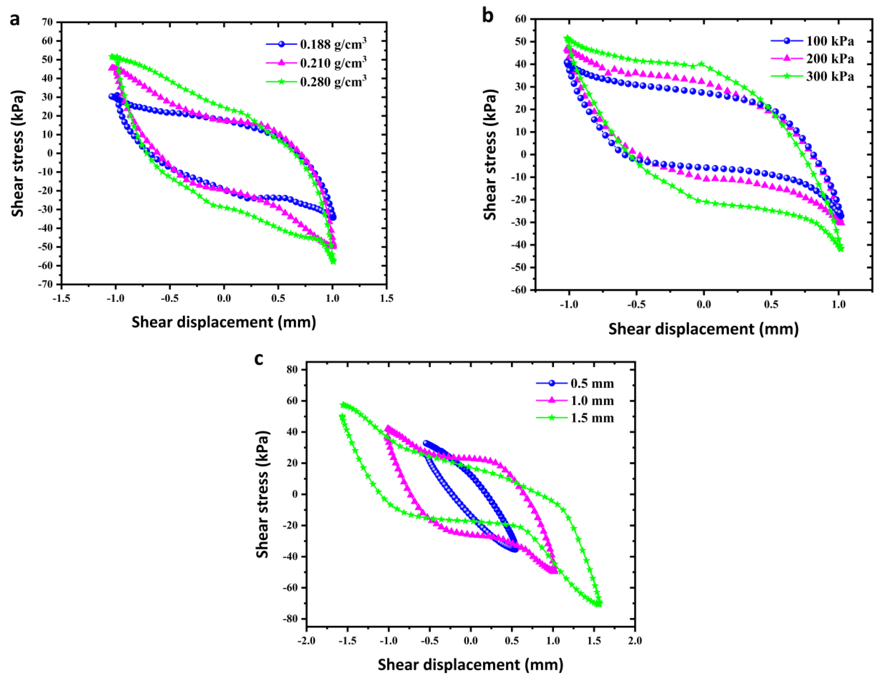
Figure 13 shows dynamic shear stress-displacement relationship curves under polymer density (a), shear amplitude (b) and vertical stress (c). The hysteresis curve depicts the process of energy absorption and dissipation at the polymer-silty clay interface, and the area in the hysteresis curve represents the magnitude of energy absorption. For varying these three factors, the variation of shear stress with shear displacement is basically the same, that is all forming a hysteresis curve with round-trip development.
In addition, it can be seen from Figure 13a that as the polymer density increases, the hysteresis loop expands gradually, the hysteresis loop area grows larger, and the peak shear stress at the interface increases to 28.9 kPa, 35.4 kPa, and 56.8 kPa, respectively. Figure 13b shows that as the shear amplitude increases from 0.5 to 1.5 mm, the hysteresis curve gradually develops from a regular ellipse to an S-shape, and the area of the hysteresis loop as well as the peak shear stress increases. From Figure 13c, it can be seen that when the vertical stress increases, the area of the hysteresis loop becomes larger, and the shear stress increases.

3.1.2. Shear Stiffness and Damping Ratio of Polymer-Soil Interface

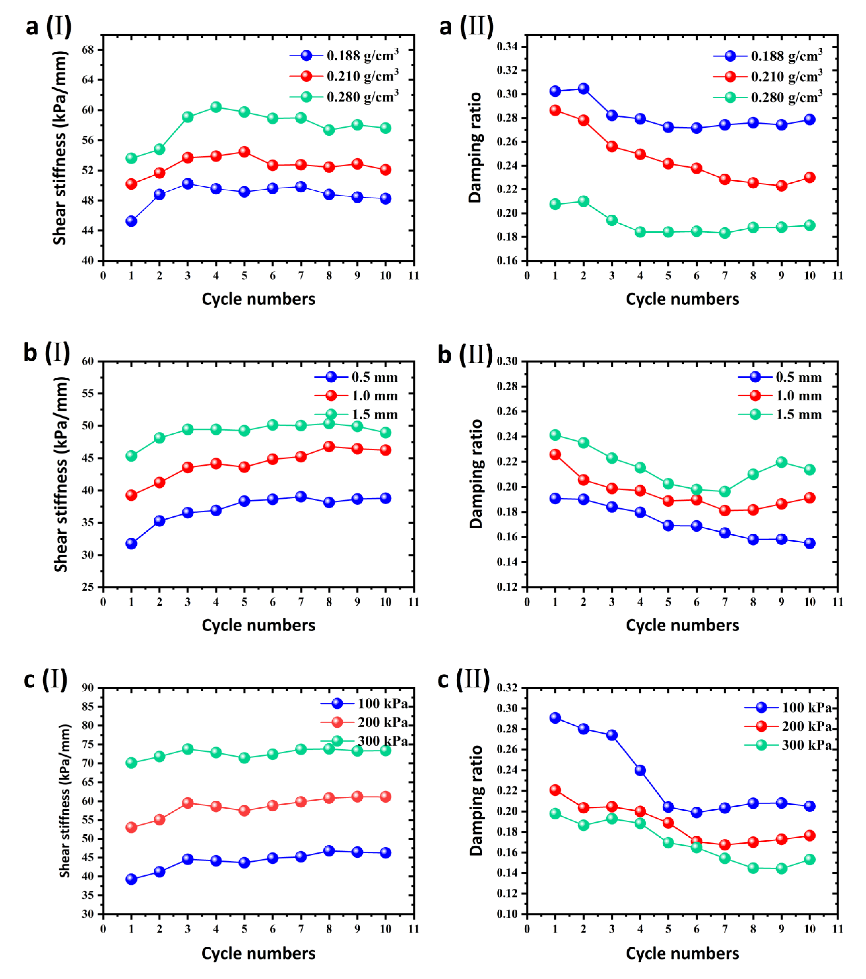
The shear stiffness of the interface is one of the parameters reflecting the resistance to shear deformation. As can be seen from Figure 14, the shear stiffness shows the similar development trend under the action of different influencing factors. The shear stiffness first grows as the cycle numbers increase, then reduces slightly after reaching the peak value, and finally tends to develop steadily. In addition, when polymer density, shear amplitude, and vertical stress increase, the shear stiffness all increases.
The damping ratio of the interface reflects the change law of the energy dissipation under the dynamic action. In general, the damping ratio decreases with the increase of the cycle numbers, and tends to develop steadily after achieving the minimum value. Furthermore, the damping ratio decreases with increasing polymer density and vertical stress, but increases with increasing shear amplitude.
In conclusion, polymer density, shear amplitude and vertical stress are the influencing factors of dynamic characteristics of the interface, and the parameters such as the shear stiffness and damping ratio can be obtained through experiments, which provide reference and basis for the construction of non-linear interface elements.

3.2. DMA Test

3.2.1. Relationship between Frequency and Dynamic Viscoelastic Modulus

Based on the DMA test, the effects of frequency and polymer density on dynamic viscoelastic modulus were obtained, and the constitutive model parameters of the polymer wall in the finite element model were obtained according to the experimental data.
The curves of storage modulus and loss factor of polymer materials with different densities (0~0.6 g/cm3) at room temperature (25 °C) were plotted in Figure 15. As can be seen from Figure 10, at room temperature, the storage modulus of polymer materials with each density increases at first and then decreases with the increase of frequency, while the loss factor first decreases slightly and then increases greatly with the increase of frequency.

3.2.2. Relationship between Polymer Density and Dynamic Viscoelastic Modulus

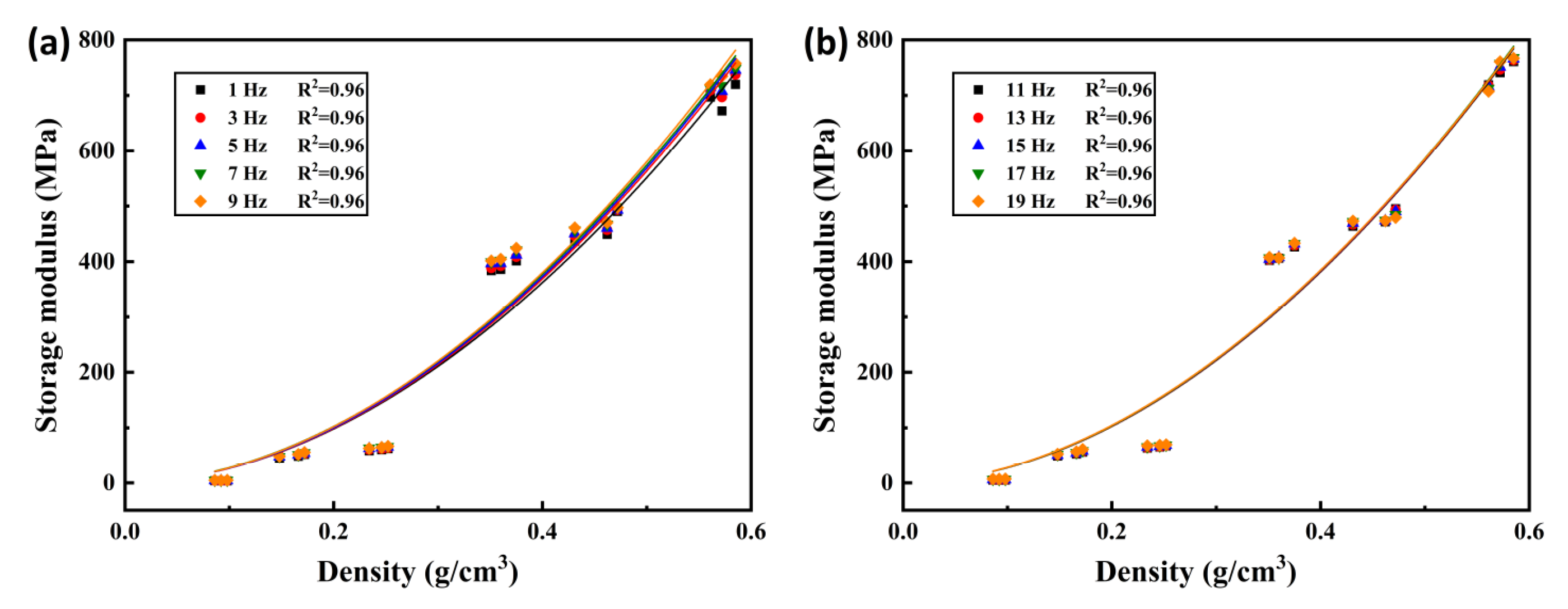
As the frequency range of dynamic loads on polymer material is typically between 1 and 19 Hz, the frequency of the scope in this study was set from 1 to 19 Hz, and the data is extracted once using the shortest interval (2 Hz). The fitting curves of storage modulus and loss modulus with polymer density were obtained from the experimental data, and the fitted results are presented in Figure 16 and Figure 17.
The storage modulus and loss modulus of the polymer at each frequency increase with the increase of density within 1–19 Hz, as shown in Figure 16 and Figure 17, and the relationship curves are basically the same. The relationship can be approximately expressed by fitting Equations (12) and (13), and their correlation coefficients R2 are greater than 0.95.
E = a ρ b
E = a ρ b
where E′ is storage modulus, E″ is loss modulus, a and b are fitting parameters.
The dynamic viscoelastic modulus of polymer at different densities was calculated according to the fitting Equations (12) and (13). Furthermore, the calculated data were fitted with the results of the fourth-order generalized Maxwell model using the Lsqcurvefit function program written by MATLAB, which can obtain the constitutive model parameters of polymer anti-seepage wall in FEM. The parameter values are shown in Table 7. For more details, one can refer to ref. [35].

4. FEM Results and Discussion

Based on the interaction model of earth-rock dam with polymer anti-seepage wall established in Section 2.3, the interaction behavior and seismic response of wall-dam considering interface characteristics was discussed.

4.1. Model Validation by Dynamic Centrifuge Test

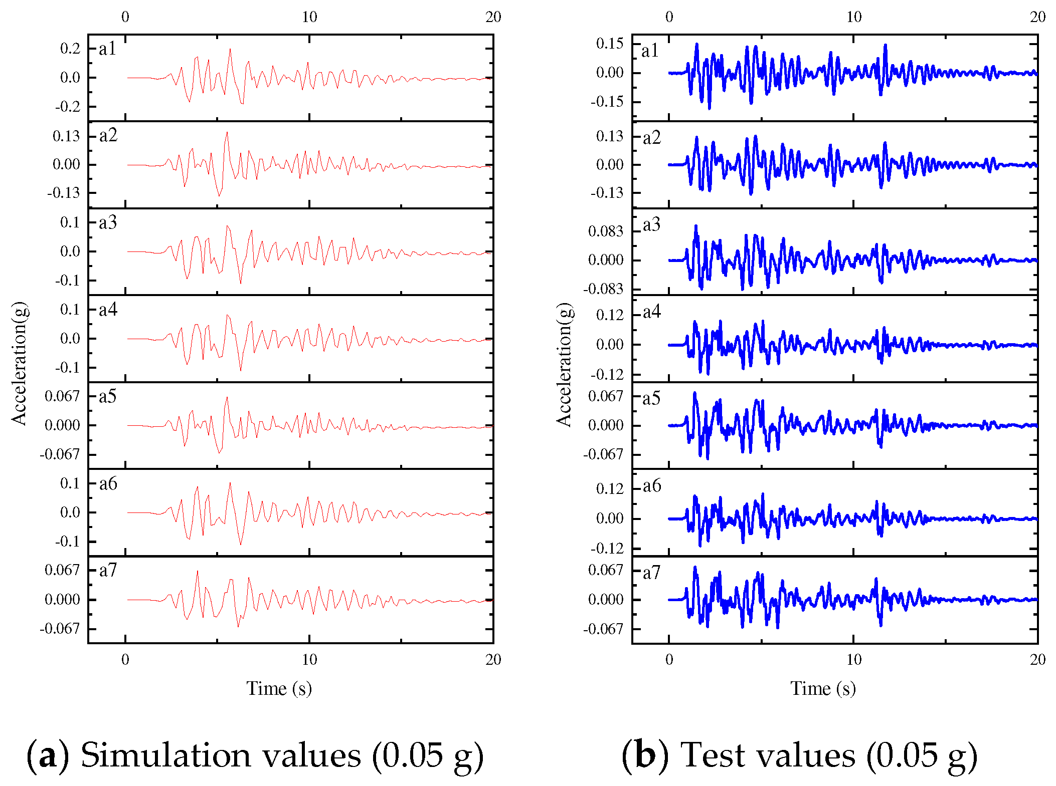
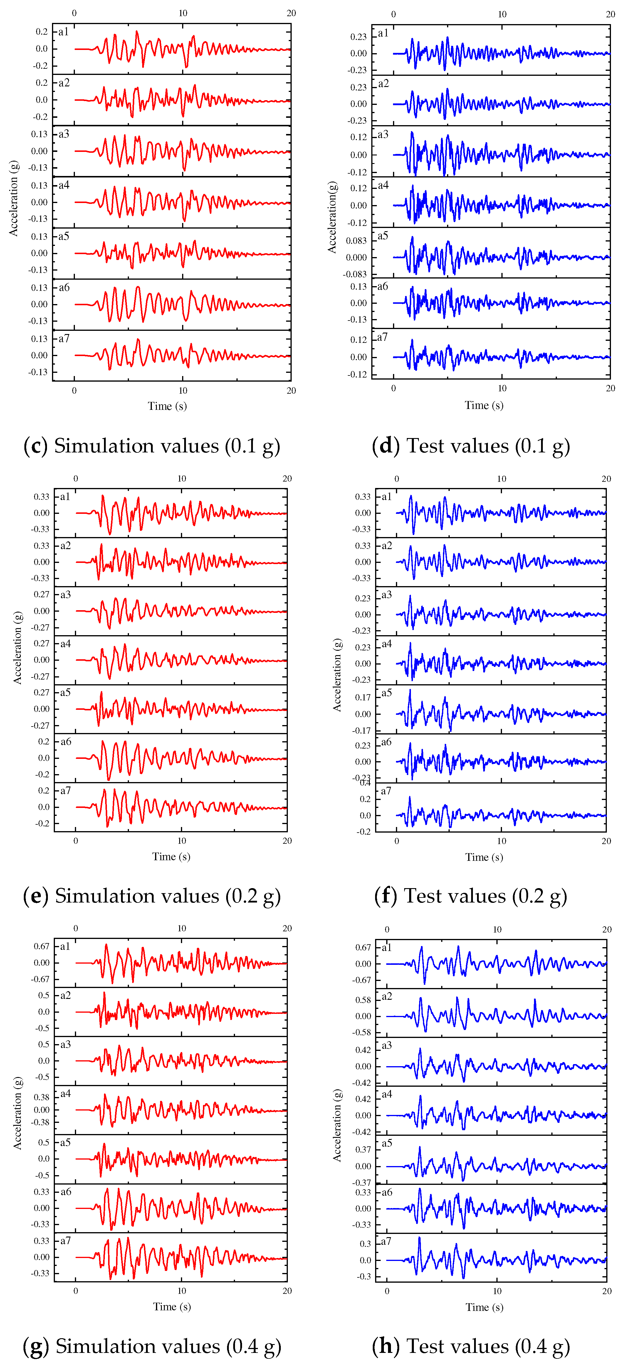
The FEM simulation and dynamic centrifuge test values of the acceleration-time history curve are shown in Figure 18. As can be seen, both results have the same trends. For more comparison, values were extracted for analysis. The test values and simulation values of three monitoring points are shown in the Table 8. From the results of Table 8, the simulation results of the wall-dam interaction model are similar to the results of the dynamic centrifugal test, and the average error between the test values and the simulation values is 14.62%, and the variance is 9.19%. The error between the two is within a reasonable range, which verifies the rationality of the wall-dam interaction model. As a result, the model can be used in a later work for a finite element analysis of the wall-dam.

4.2. Interaction Analysis

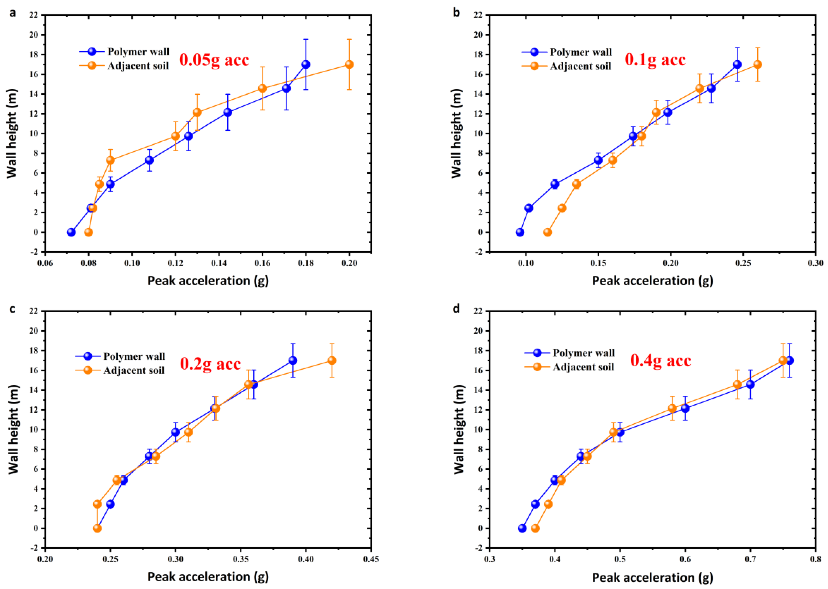
Based on the verified model, the interaction law between polymer wall and earth-rock dam under different seismic acceleration conditions can be further studied. Since the high polymer wall is established in the earth-rock dam and directly contacts with the soil, the interaction law between the high polymer wall and the adjacent soil is the focus of the study. The peak acceleration and displacement trends of the wall-dam under four conditions of seismic acceleration were investigated by taking the density of polymer wall as 0.280 g/cm3, as shown in Figure 19, Figure 20 and Figure 21, and a, b, c, d represents 0.05 g, 0.1 g, 0.2 g and 0.4 g seismic acceleration, respectively.
From Figure 19, Figure 20 and Figure 21, it can be seen that the development trends of peak acceleration, horizontal displacement and vertical displacement of the polymer wall and the adjacent soil basically coincide, showing a good synergy between the wall and the dam. Moreover, the trends specifically represent as follows: the peak acceleration increases with the increase of wall height, and the maximum value appears at the top of the wall; the horizontal displacement increases with the increase of wall height, and the maximum value appears at the top of the wall; the vertical displacement shows a trend of increasing first and then decreasing from the bottom to the top of the wall, and the maximum value appears near the middle of the wall axis. Overall, the polymer wall and the adjacent soil show highly seismic response coordination, demonstrating the good deformation coordination and interaction characteristics of the wall-dam.

4.3. Seismic Response Analysis

In addition, the wall-dam interaction model was also used to conduct the seismic response analysis. To evaluate the seismic response and investigate the seismic law of the wall-dam based on interface characteristics, three aspects of acceleration, stress, and displacement of earth-rock dam and polymer wall were investigated.

4.3.1. Peak Acceleration Analysis

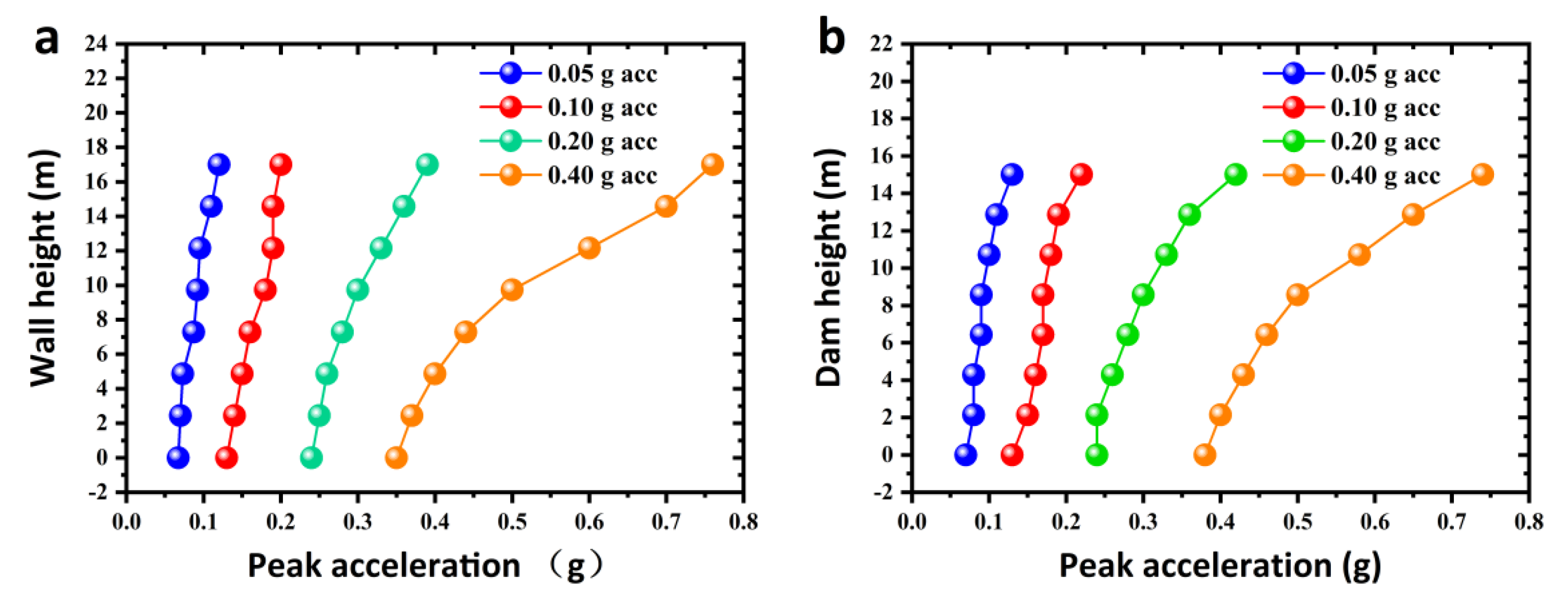
According to Figure 22, the peak acceleration of the dam and wall both grows with height, as a result, the peak acceleration at the top are the largest. In addition, the peak acceleration of the dam and wall both increases significantly as seismic acceleration increases.

4.3.2. Stress Analysis

(1)
Stress analysis of earth-rock dam
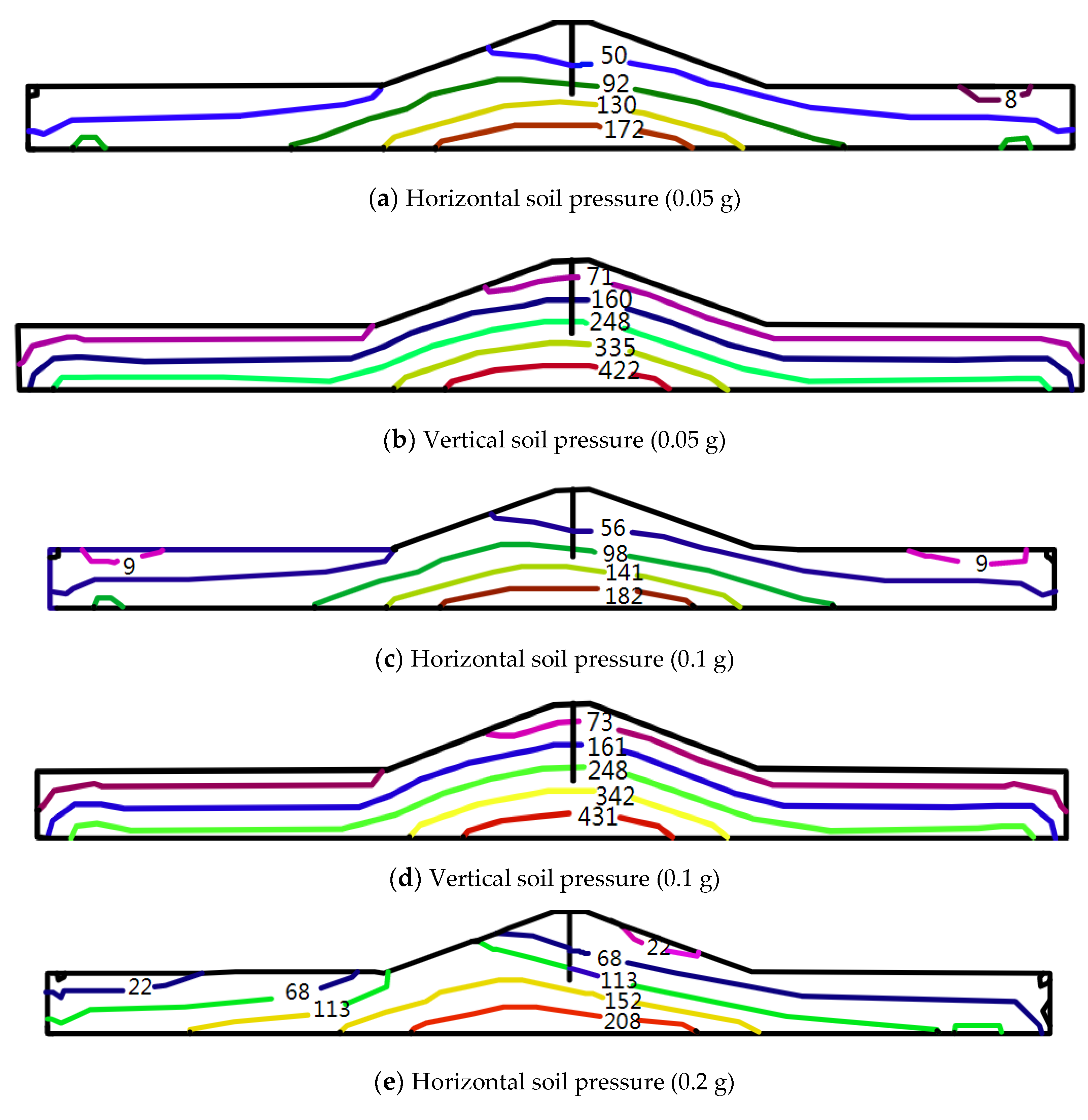
The wall-dam pressure of earth-rock dam with polymer wall contours were plotted in Figure 23.
As shown in Figure 23, the horizontal and vertical soil pressure of the dam increase with increasing seismic acceleration and decrease with increasing dam height. When the seismic acceleration is 0.05 g, 0.1 g, 0.2 g and 0.4 g, the maximum horizontal earth pressure of the earth rock dam with polymer cutoff wall is 172 kPa, 182 kPa, 208 kPa and 248 kPa, and the maximum vertical earth pressure is 422 kPa, 431 kPa, 439 kPa and 481 kPa. In addition, the horizontal soil pressure is less than the vertical soil pressure with the same earthquake acceleration.
(2)
Stress analysis of polymer wall
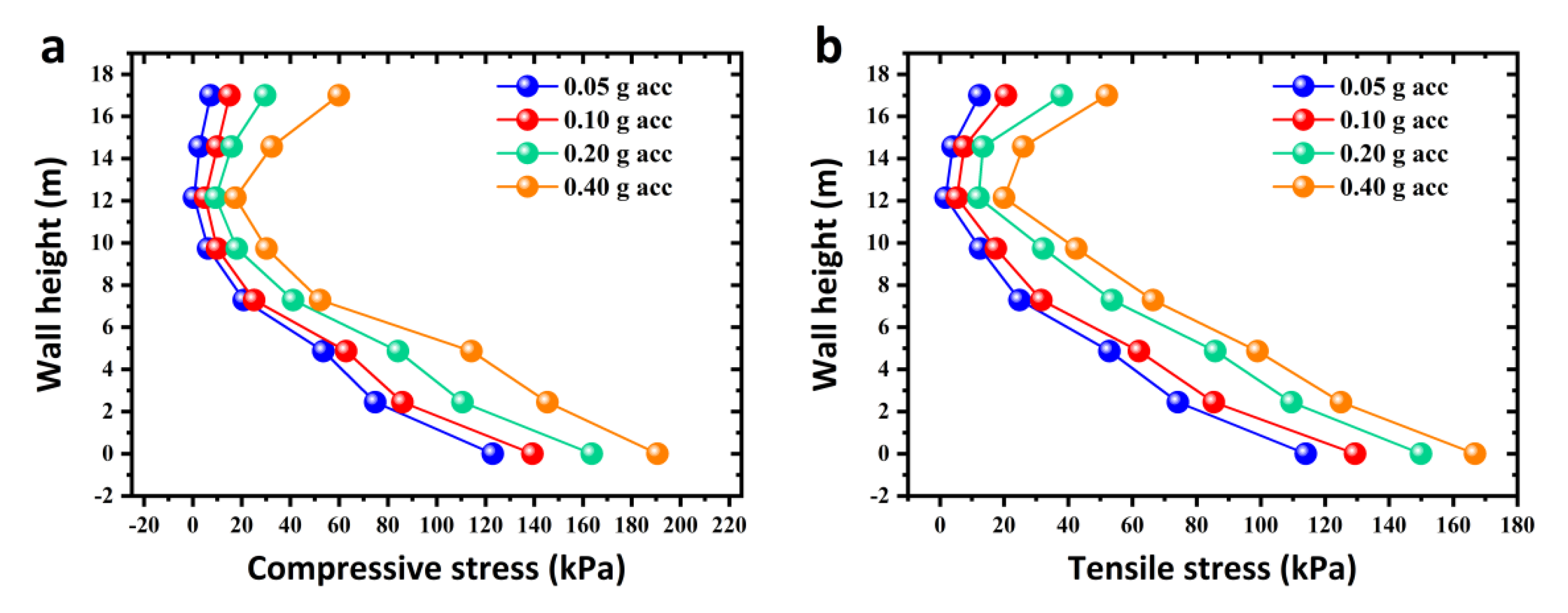
Figure 24 shows that the compressive stress and tensile stress of the wall increase as seismic acceleration increases, and that at the same seismic acceleration, the compressive stress and tensile stress first decrease and then increase from the top to the bottom of the wall, with the maximum compressive stress and tensile stress appearing at the bottom of the wall.

4.3.3. Displacement Analysis

(1)
Displacement analysis of earth-rock dam
Table 9 shows the calculated maximum horizontal and vertical displacements of the earth-rock dam with polymer wall under various earthquake accelerations. As can be seen, as seismic acceleration increases, the dam’s maximum horizontal and vertical displacements both increase.
(2)
Displacement analysis of polymer wall
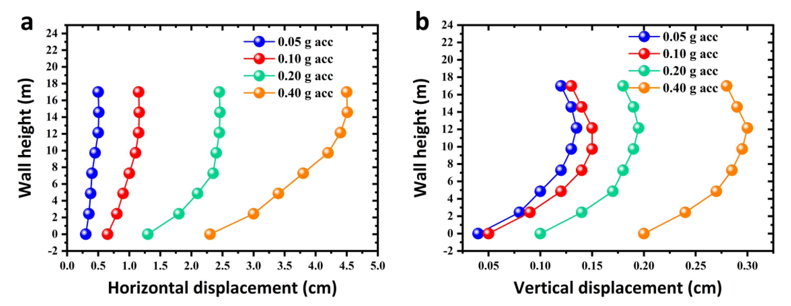
From Figure 25a, the horizontal displacement of the polymer wall gradually increases from the bottom to the top under the same seismic acceleration, with the greatest value appearing at the top. Additionally, the horizontal displacement increases with the increases of seismic acceleration, and the growth rate is the largest when seismic acceleration is 0.4 g.
From Figure 25b, under the same seismic acceleration condition, the vertical displacement increases firstly and then decreases from the bottom to the top, with the largest vertical displacement appearing in the middle of the wall axis. Furthermore, as seismic acceleration increases, vertical displacement increases as well, with the fastest vertical displacement growth rate at 0.4 g acceleration.

5. Conclusions

This section is not mandatory but can be added to the manuscript if the discussion is unusually long or complex.
In this paper, aiming at new-typed polymer anti-seepage wall, the dynamic characteristics of polymer-soil interface and the viscoelastic properties of polymer were studied by experimental tests. Then, based on tests results, the interaction behavior and seismic response of earth-rock dam with polymer anti-seepage wall were studied by FEM. The main conclusions are as follows:
(1)
The dynamic properties of the polymer-silty clay interface are affected by polymer density, shear amplitude, and vertical stress, which is specifically manifested as follows: the hysteresis loop area and dynamic shear stress of the interface increase with the increase of polymer density, shear amplitude and vertical stress. In addition, polymer density and vertical stress are positively correlated with the shear stiffness and negatively correlated with the damping ratio; shear amplitude is positively proportional to both the shear stiffness and damping ratio;
(2)
The effect of frequency and polymer density on dynamic viscoelastic modulus of polymer materials is shown in as: the storage modulus and loss modulus increase with the increase in polymer density for each frequency in the range of 1–19 Hz, which is due to the fact that density affects the number and length of molecular chains inside the material. Additionally, a fourth-order generalized Maxwell constitutive model of the polymer materials was constructed based on the power function relationship between the polymer density and the dynamic viscoelastic modulus, and the model parameters were obtained using a multi-objective constrained shared parameter fitting method, which lays a foundation for the accurate description of the mechanical properties of the polymer materials under dynamic loads;
(3)
The interaction law between the polymer wall and the earth-rock dam under earthquake are as follows: the peak acceleration, stress and displacement trends of the polymer wall and the adjacent soil are basically consistent, and the average relative difference between the two peak accelerations does not exceed 0.015 g. The average relative differences between the maximum horizontal and vertical displacements do not exceed 0.09 cm and 0.005 cm, respectively. In addition, as the seismic acceleration increases, the development trend of the mechanical response of the polymer wall and the adjacent soil are more consistent, demonstrating the good deformation coordination and interaction characteristics of the wall-dam;
(4)
The seismic response law of the wall-dam considering the interface characteristics are as follows: the peak acceleration of the wall and dam increases with height, and the maximum values occurs at the top. Additionally, the stress of the dam increases with the increase of seismic acceleration and decreases with the increase of dam height; the stress of the wall first decreases and then increases from the top to the bottom under the same seismic acceleration, and the maximum stress occurs at the bottom of the wall. Furthermore, under the 0.4 g seismic acceleration, the maximum horizontal and vertical displacement of the dam are 12.91 cm and 8.73 cm, respectively; and the maximum horizontal displacement of the wall appears at the top of the wall, while the maximum vertical displacement appears at the middle of the wall axis.

Author Contributions

Conceptualization, funding acquisition, writing—original draft: J.Z.; writing—original draft, formal analysis, validation: C.H.; formal analysis, funding acquisition, writing—review & editing: J.L.; data curation, validation: G.L. All authors have read and agreed to the published version of the manuscript.

Funding

This research was funded by the National Natural Science Foundation of China (No. 51909243) and the Key Scientific and Technological Project of Henan Province (202102310293).

Institutional Review Board Statement

Not applicable.

Informed Consent Statement

Not applicable.

Data Availability Statement

The data presented in this study are available within this article.

Acknowledgments

The authors wish to acknowledge support from the National Natural Science Foundation of China (No. 51909243) and the Key Scientific and Technological Project of Henan Province (202102310293).

Conflicts of Interest

The authors declare no conflict of interest.

References

  1. Gordan, B.; Raja, M.; Jahed Armaghani, D.; Adnan, A. Review on dynamic behaviour of earth dam and embankment during an earthquake. Geotech. Geol. Eng. 2022, 40, 3–33. [Google Scholar] [CrossRef]
  2. Li, Y.; Tang, W.; Wen, L.; Wang, J. Study on seismic failure probability of high earth-rock dam considering dam body deformation and slope stability. Eur. J. Environ. Civ. Eng. 2020, 26, 3981–3995. [Google Scholar] [CrossRef]
  3. Chai, X.; Shen, Z.; Nie, B. Study on the anti-seepage reinforcement scheme of earth-rock dam for Changli reservoir. Adv. Mater. Res. 2014, 904, 389–392. [Google Scholar] [CrossRef]
  4. Zhang, H.; Li, Z.; Li, W.; Song, Z.; Ge, W.; Han, R.; Wang, T. Risk analysis of instability failure of earth-rock dams based on the fuzzy set theory. Water 2021, 13, 3088. [Google Scholar] [CrossRef]
  5. Su, Z.; Zhang, K.; Liu, C. Dynamic risk assessment of slope stability of homogeneous earth-rock dam under action of multiple hazards. Simulation 2022, 98, 699–710. [Google Scholar] [CrossRef]
  6. Guo, C.; Chu, X.; Wang, F. Research on feasibility of non-water reaction polymer grouting technology application in seepage prevention of tailings reservoir. Water Sci. Technol. Water Supply 2017, 18, 203–213. [Google Scholar] [CrossRef]
  7. Li, J.; Zhang, J.; Xu, J.; Wang, F.; Wang, B.; Li, Q. Dynamic behavior of polymer antiseepage wall for earth dam by centrifuge test. Int. J. Geomech. 2018, 18, 04018179. [Google Scholar] [CrossRef]
  8. Li, J.; Zhang, J.; Wang, Y.; Wang, B. Seismic response of earth dam with innovative polymer antiseepage wall. Int. J. Geomech. 2020, 7, 04020079. [Google Scholar] [CrossRef]
  9. Chen, S.; Li, J.; Zhang, J. Research on dynamic soil pressure of earth dam with polymer anti-seepage wall. In Proceedings of the 5th International Conference on Information Science and Control Engineering, Zhengzhou, China, 20–22 July 2018; pp. 454–458. [Google Scholar] [CrossRef]
  10. Fang, H.; Zhang, H.; Xue, B.; Gao, J.; Li, Y.; Gao, X.; Tian, A. Coordination characteristics analysis of deformation between polymer anti-seepage wall and earth dam under traffic load. Water 2022, 14, 1442. [Google Scholar] [CrossRef]
  11. Li, J.; Zhang, J.; Hu, H. Numerical analysis on dynamic responses of earth-rock dam with polymer anti-seepage wall under seismic load. In Proceedings of the 3rd International Conference on Information Science and Control Engineering, Beijing, China, 8–10 July 2016; pp. 492–496. [Google Scholar] [CrossRef]
  12. Wang, F.; Guo, C.; Gao, Y. Formation of a polymer thin wall using the level set method. Int. J. Geomech. 2014, 14, 04014021. [Google Scholar] [CrossRef]
  13. Wang, Y.; Wan, Y.; Guo, C.; Zeng, C.; Shao, J.; Wang, F. Experimental investigation on the monotonic, cyclic and post cyclic interfacial behavior of non-water reacted polymer and concrete. Constr. Build. Mater. 2021, 292, 123323. [Google Scholar] [CrossRef]
  14. Qin, L.; Guo, C.; Sun, W.; Guan, H.; Yan, W.; Wang, F. Experimental investigation on the interfacial shear bond performance of non-water reacting polymer and concrete. Constr. Build. Mater. 2022, 331, 127351. [Google Scholar] [CrossRef]
  15. Ma, X.; Wang, F.; Guo, C.; Sun, B. Seismic isolation effect of non-water reacted two-component polymeric material coating on tunnels. Appl. Sci. 2020, 10, 2606. [Google Scholar] [CrossRef] [Green Version]
  16. Shi, M.; Wang, F.; Liu, H.; Guo, C. Finite-element simulation and experiment on polymer directional fracturing and grouting for dykes and dams. J. Hydraul. Eng. 2016, 47, 1087–1092. [Google Scholar] [CrossRef]
  17. Li, J.; Zhang, J. Study on the seismic response of polymer anti-seepage wall. In Proceedings of the 4th International Conference on Information Science and Control Engineering, Changsha, China, 21–23 July 2017; pp. 1268–1272. [Google Scholar] [CrossRef]
  18. Kishida, H.; Uesugi, M. Tests of interfaces between sand and steel in simple shear apparatus. Geotechnique 1987, 37, 45–52. [Google Scholar] [CrossRef]
  19. Zhu, J.; Shakir, R.; Yang, Y.; Peng, K. Comparison of behaviors of soil-concrete interface from ring-shear and simple shear tests. Rock Soil Mech 2011, 32, 692–696. [Google Scholar] [CrossRef]
  20. Toki, K.; Sato, T.; Miura, F. Separation and sliding between soil and structure during strong ground motion. Earthq. Eng. Struct. Dyn. 1981, 9, 263–277. [Google Scholar] [CrossRef]
  21. Wang, Z.; Gao, L.; Song, W. Finite element analysis of 3-D friction-contact problems. J. Tsinghua Univ. 2002, 42, 93–96, 104. [Google Scholar]
  22. Qi, Y.; Feng, Z.; Yu, J.; Liu, C. Research on 3D dynamic nonlinear aseismic calculation of pile group foundation of north tower of Taizhou bridge. Chin. J. Rock Mech. Eng. 2010, 29, 3071–3081. [Google Scholar]
  23. Zhao, C.; Xu, T.; Valliappan, S. Seismic response of concrete gravity dams including water-dam-sediment-foundation interaction. Comput. Struct. 1995, 54, 705–715. [Google Scholar] [CrossRef]
  24. Schenck, H. An efficient and accurate numerical technique for low-frequency scattering from elastic bodies. Acoust. Soc. Am. J. 1988, 84, 185. [Google Scholar] [CrossRef]
  25. Liu, X.; Xu, Y.; Jin, F.; Wang, G.; Zhang, C. Nonlinear responses of high arch dams to nonuniform free field motion due to seismic input. J. Tsinghua Univ. 2003, 43, 1567–1571. [Google Scholar] [CrossRef]
  26. Li, J.; Zhang, J.; Chen, S. Study on dynamic viscoelastic properties and constitutive model of non-water reacted polyurethane grouting materials. Measurement 2021, 176, 109115. [Google Scholar] [CrossRef]
  27. Li, J.; Wang, B.; Zhang, J. Dynamic centrifuge test on seismic acceleration response of earth dike and dam with polymer anti-seepage wall. Earthq. Eng. Eng. Dyn. 2016, 36, 1–6. [Google Scholar] [CrossRef]
  28. Li, J.; Ma, G.; Zhao, J. An equivalent viscoelastic model for rock mass with parallel joints. J. Geophys. Res. 2010, 115, B03305. [Google Scholar] [CrossRef] [Green Version]
  29. Deeks, A.; Randolph, M. Axisymmetric time-domain transmitting boundaries. J. Eng. Mech. 1994, 120, 25–42. [Google Scholar] [CrossRef]
  30. Du, X.; Zhao, M.; Wang, J. A stress artificial boundary in FEA for near-field wave Problem. Chin. J. Theor. Appl. Mech. 2006, 38, 49–56. [Google Scholar] [CrossRef]
  31. Arivazhagan, R.; Krishnamurthy, P. Influence of Grain Size and Its Distribution on Hyperbolic Model Parameters for Dry Sand. J. Comput. Theor. Nanosci. 2018, 15, 995–1003. [Google Scholar] [CrossRef]
  32. Tian, X.; Xiao, H.; Li, Z.; Li, Z.; Su, H.; Ouyang, Q. Experimental Study on the Strength Characteristics of Expansive Soils Improved by the MICP Method. Geofluids 2022, 2022, 3089820. [Google Scholar] [CrossRef]
  33. Nam, S.; Gutierrez, M.; Diplas, P.; Petrie, J. Determination of the shear strength of unsaturated soils using the multistage direct shear test. Eng. Geol. 2011, 122, 272–280. [Google Scholar] [CrossRef]
  34. Clough, G.; Duncan, J. Finite element analyses of retaining wall behavior. J. Soil Mech. Found. Div. 1971, 97, 1657–1673. [Google Scholar] [CrossRef]
  35. Zhang, J.; Li, J.; Huang, C.; Chen, S. Study on dynamic viscoelastic constitutive model of nonwater reacted polyurethane grouting materials based on DMA. Rev. Adv. Mater. Sci. 2022, 61, 238–249. [Google Scholar] [CrossRef]
  36. Lv, H.; Liu, H.; Tan, Y.; Meng, A.; Cyriaque, A.; Xiao, S. An extended search method for identifying optimal parameters of the generalized Maxwell model. Constr. Build. Mater. 2021, 266, 120796. [Google Scholar] [CrossRef]
Figure 1. Engineering application of new-typed polymer materials.
Sustainability 14 14357 g001
Figure 2. Contact state between polymer and soil.
Sustainability 14 14357 g002
Figure 3. Sample mould and sample for polymer-soil interface ring shear test.
Sustainability 14 14357 g003
Figure 4. Sample mould and sample for DMA test.
Sustainability 14 14357 g004
Figure 5. Sample for dynamic centrifuge test.
Sustainability 14 14357 g005
Figure 6. SRS-150 dynamic ring shear apparatus.
Sustainability 14 14357 g006
Figure 7. Dynamic thermo-mechanical analysis instrument.
Sustainability 14 14357 g007
Figure 8. Dynamic centrifuge test equipment and model. (a) ZJU-400 geotechnical centrifuge equipment. (b) Dynamic centrifuge test model.
Sustainability 14 14357 g008
Figure 9. Cross-sectional diagram of the Jiulong reservoir earth-rock dam.
Sustainability 14 14357 g009
Figure 10. Schematic diagram of model meshing.
Sustainability 14 14357 g010
Figure 11. Operation flow chart of non-liner interface element.
Sustainability 14 14357 g011
Figure 12. Generalized Maxwell model.
Sustainability 14 14357 g012
Figure 13. Dynamic shear stress-displacement relationship curves under different factors: (a) polymer density; (b) shear amplitude; (c) vertical stress.
Sustainability 14 14357 g013
Figure 14. Trend chart of shear stiffness and damping ratio under different factors: (a) polymer density; (b) shear amplitude; (c) vertical stress.
Sustainability 14 14357 g014
Figure 15. Frequency spectra of storage modulus and loss factor of high polymer materials at different densities.
Sustainability 14 14357 g015
Figure 16. Relationship between density and storage modulus of high polymer materials (25 °C) under different frequency: (a) 1–9 Hz; (b) 11–19 Hz.
Sustainability 14 14357 g016
Figure 17. Relationship between density and loss modulus of high polymer materials (25 °C) under different frequency: (a) 1–9 Hz; (b) 11–19 Hz.
Sustainability 14 14357 g017
Figure 18. Acceleration-time history curve of wall-dam.
Sustainability 14 14357 g018aSustainability 14 14357 g018b
Figure 19. Development trend of peak acceleration under different seismic acceleration: (a) 0.5 g; (b) 0.1 g; (c) 0.2 g; (d) 0.4 g.
Sustainability 14 14357 g019
Figure 20. Development trend of horizontal displacement under different seismic acceleration: (a) 0.5 g; (b) 0.1 g; (c) 0.2 g; (d) 0.4 g.
Sustainability 14 14357 g020
Figure 21. Development trend of vertical displacement under different seismic acceleration: (a) 0.5 g; (b) 0.1 g; (c) 0.2 g; (d) 0.4 g.
Sustainability 14 14357 g021
Figure 22. Trend chart of peak acceleration of wall (a) and dam (b).
Sustainability 14 14357 g022
Figure 23. Earth-rock dam soil pressure contours.
Sustainability 14 14357 g023aSustainability 14 14357 g023b
Figure 24. Stress trend of polymer wall: (a) compressive stress; (b) tensile stress.
Sustainability 14 14357 g024
Figure 25. Displacement trend of polymer wall: (a) horizontal displacement; (b) vertical displacement.
Sustainability 14 14357 g025
Table 1. Physical parameters of polymer.
Test TypesDensity
ρ (g/cm3)
Permeability Coefficient
k (cm/s)
Elastic Modulus
E (MPa)
Poisson’s Ratio μ
Ring shear test0.1~0.31 × 10−818.36~72.190.11~0.24
Viscoelastic test0.1~0.61 × 10⁻⁸~1 × 10−918.36~160.350.11~0.52
Dynamic centrifuge test0.261 × 10−858.110.20
Table 2. Physical parameters of silty clay.
Specific Gravity
Gs
Void Ratio
e
Water
Content
ω (%)
Permeability
Coefficient
k (cm/s)
Elastic Modulus
E (MPa)
Poisson’s Ratio
μ
Cohesion
C (kPa)
Internal
Friction Angle
φ (°)
2.70.804212.3 × 10−537.20.3522.211.3
Table 3. Ring shear test scheme.
Shear ModeTest NumberInterface TypePolymer
Density
Cyclic AmplitudeVertical Stress
(g/cm3)(mm)(kPa)
Cyclic shearA-1Polymer-silty clay0.1881.0100
A-20.210
A-30.280
Cyclic shearB-1Polymer-silty clay0.1880.5100
B-21.0
B-31.5
Cyclic shearC-1Polymer-silty clay0.1881.0100
C-2200
C-3300
C-4400
Table 4. DMA test scheme.
Test MethodTemperatureFrequencyDensity
Three-point bending method−50 °C, −25 °C, 0 °C, 25 °C, 50 °C1~40 Hz0~0.6 g/cm3
Table 5. Dynamic centrifuge test scheme.
Seismic Wave AmplitudeInput Seismic WaveformDurationWater Level
0.05 gEl-Centro wave20 s8.6 cm
0.1 gEl-Centro wave20 s8.6 cm
0.2 gEl-Centro wave20 s8.6 cm
0.4 gEl-Centro wave20 s8.6 cm
Table 6. Constitutive model parameters of earth-rock dam.
MaterialsK m v
Dam body5000.50.30
Dam foundation5000.50.30
Table 7. Constitutive model parameters of polymer anti-seepage wall.
ρ (g/cm3)g1g2g3g4τ1 (s)τ2 (s)τ3 (s)τ4 (s)
0.1880.06970.09190.07850.58956.268313.56870.12500.0001
0.2100.03060.01580.01960.14735.91013.13070.11160.0001
0.2800.06430.11030.06860.54121.60821.52690.08240.0002
Table 8. Peak acceleration of dam axis.
Seismic
Acceleration
Monitoring Point a1 (g)Monitoring Point a2 (g)Monitoring Point a3 (g)
TestSimulationTestSimulationTestSimulation
0.05 g0.190.20.140.120.10.12
0.1 g0.230.260.220.170.160.15
0.2 g0.430.480.360.340.270.25
0.4 g0.830.880.710.690.470.51
Table 9. Displacement calculation value of earth-rock dam.
Earthquake AccelerationMaximum Horizontal DisplacementMaximum Vertical
Displacement
0.05 g1.22 cm1.48 cm
0.1 g1.81 cm1.66 cm
0.2 g3.63 cm3.45 cm
0.4 g12.91 cm8.73 cm
Publisher’s Note: MDPI stays neutral with regard to jurisdictional claims in published maps and institutional affiliations.