Abstract
This paper proposes a method of detecting driving vehicles, estimating the distance, and detecting whether the brake lights of the detected vehicles are turned on or not to prevent vehicle collision accidents in highway tunnels. In general, it is difficult to determine whether the front vehicle brake lights are turned on due to various lights installed in a highway tunnel, reflections on the surface of vehicles, movement of high-speed vehicles, and air pollution. Since driving vehicles turn on headlights in highway tunnels, it is difficult to detect whether the vehicle brake lights are on or not through color and brightness change analysis in the brake light area only with a single image. Therefore, there is a need for a method of detecting whether the vehicle brake lights are turned on by using a sustainable change obtained from image sequences and estimated distance information. In the proposed method, a deep convolutional neural network(DCNN) is used to detect vehicles, and inverse perspective mapping is used to estimate the distance. Then, a long short-term memory (LSTM) Network that can analyze temporal continuity information is used to detect whether the brake lights of the detected vehicles are turned on. The proposed method detects whether or not the vehicle brake lights are turned on by learning the long-term dependence of the detected vehicles and the estimated distances in an image sequence. Experiments on the proposed method in highway tunnels show that the detection accuracy of whether the front vehicle brake lights are turned on or not is 90.6%, and collision accidents between vehicles can be prevented in highway tunnels.
1. Introduction
Recently, vehicles have become a means of daily life, away from simply transportation. As such, vehicles have become an indispensable part of our daily life. In particular, the advent of autonomous vehicles, a technology that allows a driver to autonomously drive to a desired destination without concentrating on the driving task is being realized. However, in reality, the realization of fully autonomous driving, that is, an environment in which the driver does not intervene at all in the driving task, still needs more time. For the realization of autonomous driving, safe driving is essential, and related technologies are continuously being developed and applied to vehicles [1,2,3]. In addition, technologies for vehicle safety support are also applied to road infrastructure facilities such as road signs, lanes, traffic lights, and tunnels for safety driving. However, while various safe driving support technologies applicable to road infrastructure and vehicles have been applied so far, research on supporting drivers’ driving concentration for safe driving is insufficient. For example, it often occurs in situations where one cannot focus on all directions due to smartphone manipulation while driving, multimedia viewing, and conversation with passengers, which can eventually lead to traffic accidents. Therefore, it is necessary to develop a technology focusing the driver’s forward attention.
Figure 1 is the result of comparing the number of deaths per 10,000 vehicles from 2015 to 2018 in major the Organization for Economic Co-operation and Development (OECD) countries. It can be seen from the comparison results that the death accident rate is gradually decreasing. However, in the case of Korea, the number of traffic accident deaths is relatively higher than in other major OECD countries [4]. In order to reduce vehicle traffic accidents, each country is improving the structure of road infrastructure (road, tunnel, traffic signs, etc.), strengthening vehicle manufacturing standards, and strengthening driver safety education, leading to a decrease in traffic accidents and deaths every year.
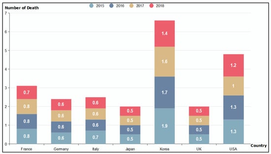
Figure 1.
Comparison of the number of deaths of 10,000 vehicles by OECD countries [4].
As shown in Figure 2, according to the traffic accident analysis system of the Korea Road Traffic Authority, the number of traffic accidents and deaths decreased by −8% from 2016 to 2019 [5]. However, the ratio of traffic accident deaths occurring in road tunnels exceeds 2% on average compared to all road traffic accidents. In particular, despite the decrease in the number of fatalities due to traffic accidents along with the increase in the number of vehicles since 2017, the ratio of fatalities in highway tunnels is still increasing.
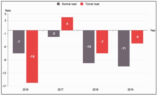
Figure 2.
Rate of change in the number of deaths due to traffic accidents on general and tunnel roads in Korea [5].
In the case of Korea, 70% of the land is mountainous, and the number of tunnels is increasing every year along with the expansion of roads, resulting in an increase in the number of deaths caused by accidents in highway tunnels. The highway tunnel structure is semi-enclosed, so one accident can lead to a major accident. In particular, since there are many driving vehicles in the tunnel, it is easy to cause a fire or an explosion, which may result in a large number of casualties. The fatality rate of traffic accidents occurring in highway tunnels and bridges in Korea was about twice as high as that of the total traffic accidents. According to Korea’s Road Traffic Authority Traffic Accident Analysis System (TAAS), a total of 3452 traffic accidents occurred in tunnels over the past five years (2015–2019) and 6789 accidents on bridges (1358 accidents per year). The average annual traffic accident fatality rate (the number of fatalities per 100 traffic accidents) was 3.6 in tunnels and 4.1 on bridges, which was more than double the fatality rate for all traffic accidents at 1.8. This cause can be analyzed as a large amount of damage in case of traffic accidents due to the characteristics that it is difficult to avoid accidents in road tunnels and bridges. Road tunnels feel narrow due to the driver’s visual limitations, and as they enter from bright to dark, the front of the driving road tunnel is difficult to see. That is, for a short time, the driver may not be able to grasp the traffic situation of the road tunnel. In addition, since road tunnels mainly penetrate mountainous terrain, it can be difficult to control vehicles due to slopes, curves, bridges, gusts, and strong winds after passing through the tunnel.
Highway tunnels are a structure necessary for road construction even in difficult terrain by overcoming the safety of driving vehicles and natural conditions. It is the best way to minimize damage to the environment and land due to road tunnels and to reduce traffic congestion and air pollution while preserving land support. After all, when designing road tunnels, it will be necessary to design them in a straight line as possible to minimize the occurrence of traffic accidents, and to build them in accordance with the geometric design principles of open roads. Due to the characteristics of the road tunnel environment, the fatality rate in the event of a traffic accident is higher. The highway tunnels are more closed than general road environments, and in the event of a traffic accident, the fatality rate is likely to be high due to heat, smoke, and vehicle exhaust concentration problems.
In a previous research, it was investigated that collisions between vehicles in road tunnels or collisions with tunnel walls occur more frequently in the tunnel entrance area [6,7]. In addition, Kerstin L. [8] and Mashimo H. [9] have proven that, when the length of the tunnel is long, it has a negative effect on safe driving due to a decrease in the driver’s concentration. Traffic accidents in tunnels are rarely affected by the weather, but on rainy and snowy days, road pavement friction coefficients are low, so accidents are likely to occur at the entrance and exit of the tunnel. In particular, most road tunnel traffic accidents are analyzed as rear collisions, and it was investigated that many traffic accidents were caused by driver carelessness [9]. According to the research of [10], the number of road tunnel traffic accidents in China in 2016 increased by 25% compared to 2012, suggesting that most accidents are related to rear-end collisions of vehicles in tunnels. The cause of traffic accidents in the tunnel is that the inside of the tunnel has a low luminance compared to general roads. Eventually, it becomes an environment in which vehicle drivers are prone to fatigue and sleepiness, and the lack of attention can lead to traffic accidents. This lack of attention can lead to careless operation of the vehicle, and the amount of visual information can be reduced to about 2/3 of that of a general road area, leading to increased fatigue and distraction of attention. Among the various structures installed in the tunnel, the tunnel lights are arranged at regular intervals, so that a high luminance value is repeatedly introduced at the driver’s point of view in a short time from the perspective of a driver driving a road tunnel. This repetitive pattern is easy for the driver to be bored and sensitivity may decrease due to repeated visual stimulation.
As such, research studies so far have focused on improving the road tunnel infrastructure, but only focusing on safe driving education as a way to focus the driver’s attention on driving. Forward attention to prevent traffic accidents while driving should be mitigated in all road environments, but especially in road tunnels, it is necessary to strengthen the concentration of attention while driving. As in previous research, in highway tunnels, the driver’s anxiety increases due to the closed environment of the tunnel, which leads to a tendency not to recognize the sense of speed of the vehicle. Moreover, fatigue may be increased due to the monotony of the tunnel structure, and there is a problem in that it is difficult to detect an omnidirectional vehicle collision in advance due to a decrease in the sense of speed. To solve this problem, rainbow lights and siren sounds are installed in highway tunnels as shown in Figure 3.
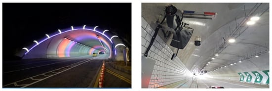
Figure 3.
Examples of installing LED lights and sound devices for driver’s attention in the highway tunnel ((left) [11], (right) [12]).
This paper proposes a method to detect a vehicle driving from an image obtained by a CCD camera attached to a vehicle, estimate a distance, and then detect whether the front vehicle brake lights are turned on. Most of the existing investigations to determine whether the brake lights are turned on or not are to detect whether the brake lights are operating or not by detecting changes in the brightness or color of the brake lights area in a single image [13,14,15]. However, in most cases, when a vehicle enters a road tunnel, the vehicle’s headlights or taillights are automatically turned on due to illumination sensors. Accordingly, when the headlight or taillight is turned on without deceleration of the vehicle in the tunnel, the brake lights are also turned on. As a result, there is a need for a method of detecting whether the brake lights are turned on when the vehicle is continuously decelerating. The proposed method uses a long short-term memory (LSTM) network that can measure temporal changes in vehicle distance estimation information and detected vehicle regions in an image sequence. An LSTM learns long-term dependencies between time steps in time series and sequence data [15]. In order to detect whether a vehicle brake is operated or not, a spatio-temporal change is utilized that analyzes vehicle distance information and brightness and color information of vehicle brake lights in an image sequence. The proposed method uses a you only look once version 4 (YOLO v4) deep learning network to detect driving vehicles in a highway tunnel. Moreover, it detects whether the front vehicle brake lights are turned on by using the LSTM network that has learned the change of information according to temporal continuity.
1.1. Previous Research
The sudden braking of a preceding vehicle in a highway tunnel leads to a series of collisions with the following vehicles. Traffic accidents in highway tunnels result in large-scale casualties due to the absence of evacuation zones. Accordingly, it is essential to secure a safe distance between driving vehicles in highway tunnels. Several researchers are proposing ways to maintain a safe distance by detecting the brake lights of a preceding vehicle to maintain a distance between vehicles in highway tunnels. In order to detect whether the front vehicle brake lights are turned on, machine vision-based and deep learning-based research is being conducted. In machine vision-based vehicle brake light lighting detection research [13], research is being conducted based on the number of red color pixels of vehicle brake lights using RGB color information.
The method proposed by [14] used the you only look once version 3 (YOLO v3) vehicle detectors trained on 100,000 COCO datasets to detect vehicles in input images. Then, in order to detect whether the brake lights of the detected vehicle are turned on or not, the RGB color space of the detected vehicle region is converted into a L*a*b color space and then learned using a random forest algorithm. The proposal assumes that there are brake lights at the center of the vehicle and that there are no brake light failures. High-definition input images are required by performing L*a*b color space filtering to perform learning on images that are turned on and off. In addition, when the vehicle taillights are automatically turned on in a low-illuminance environment such as in a road tunnel, there is a problem in that the brake lights may be mis-detected as being turned on. Additionally, the random forest algorithm has a disadvantage in that it consumes a lot of memory during training.
In the method for detecting whether the vehicle brake lights are turned on or not, proposed by [16], the vehicle is first detected using the YOLO object detector. Moreover, after converting the color space of the detected vehicle region into the L*a*b color space, a method using the support vector machine (SVM) learner was proposed. Their proposed method is a method to detect whether vehicle brake lights are turned on general roads during the daytime, and a detection accuracy of about 96.3% was presented.
In the method proposed by [17], a feature was extracted and learned from labeled vehicle regions using a pre-trained AlexNet model to detect vehicles. The vehicle is detected using the trained AlexNet object detector, and the location is determined using the brake lights pattern in the detected vehicle region. In their method, it is necessary to generate brake light patterns in advance from a large database of vehicle rear images. However, there is a problem that the patterns of brake lights differ depending on the size, type, and shape of the vehicle, and the patterns may vary depending on the type of vehicle in the vehicle database built in advance.
Liu, et al. [18] proposed detecting forward-driving vehicles to prevent vehicle rear collision warnings and detecting whether RGB color information-based vehicle braking was operated. The proposed method uses a Haar-based AdaBoost cascade classifier to detect vehicles. Then, the position of the vehicle brake lights is detected using the color, shape, and structural characteristic information of the detected vehicle between image frames. Moreover, it is detected whether the change of the RGB color value at the vehicle brake lights position is turned on using the threshold method. Their proposal is a method applicable to daytime hours and has limitations in application in places where various lighting and environments change, such as road tunnels.
Li. et al. [19] proposed a method to detect whether vehicle lights are turned on using the YOLO v3-tint model. The proposed method uses a spatial pyramid pooling module to detect whether vehicle lights are turned on despite various shapes of vehicles to improve detection accuracy during neural network learning.
In the method proposed by [13], the Deformable part model was used to detect vehicles. If the pixel luminance value in the vehicle-lights area of the detected vehicle is above the threshold, brake lights are turned on. The proposed method can be applied only during the daytime, and there is a problem in that the accuracy is lowered when it is polluted by noise, such as rain or road tunnels.
In previous research, RGB color changes were used in a single image to detect whether vehicle brake lights were turned on. Recently, research has been conducted to detect whether vehicle brake lights that have been learned in advance are turned on by applying a deep learning-based method. In previous research, it was a method that could be applied to the daytime in relatively high-resolution images. Therefore, there is a need for a method for detecting whether the front vehicle brake lights are turned on relatively accurately even in an environment in which various diffuse reflections exist due to the tunnel lighting lamp and the vehicle headlights in the highway tunnel. In addition, a method for detecting whether vehicle lights are turned on or not by using spatiotemporal characteristic information in continuous image frames is required.
1.2. Artificial Neural Networks (ANN)
The ANN model is a model created by imitating neurons, which are neurons in the human brain, and is a structure in which neurons connected by weights are composed of layers [20]. The neural network repeats learning through a large number of input and output values, and trains to minimize the error by adjusting the weights. An important feature of a neural network is a neural network structure that describes the connections between neurons and a learning algorithm used to find weights for transforming input values into desired output values. In the ANN model, the connection structure between neurons is a feedforward neural network, and a typical learning algorithm used is a backpropagation algorithm. In the backpropagation algorithm, the direction of data is forward from input to output, but weight learning is conducted in the reverse direction using errors. However, the ANN model has disadvantages in that it is difficult to find optimal parameter values in the learning process, overfitting problems and the learning time is too slow. Deep NN is a model designed to compensate for the overfitting problem that appears in the ANN model and is a neural network with two or three or more hidden layers [21]. In the recurrent neural network (RNN) model, the information of the hidden layer at the previous time is connected to the input of the hidden layer at the current time through the internal circulation structure. However, there is a problem in that learning ability is deteriorating because it is difficult to use past data as information about weights at the present time. To solve this problem, a new model, LSTM, has been proposed [15,20].
1.3. Long Short-Term Memory (LSTM)
Since the RNN model has a problem in that training performance is poor for past data, the LSTM model was proposed to compensate for this [15]. The LSTM model has the ability to perform learning that requires a long dependence period. This model includes memory cells that can hold information in memory for a long time, and long-term dependencies can be learned from these memory cells. The LSTM model is a structure in which cells are added to the hidden layer of RNN. However, unlike RNN, by using the forget gate, input gate, and output gate to adjust and control information in the internal circulation structure, it is possible to effectively transmit information without losing information in the long term. LSTM is one of the RNN techniques that have strengths in learning time series data. RNN has a vanishing gradient problem in which the learning ability is greatly reduced when the length between the relevant information and the point where the information is used in the learning process is long. It has been developed to overcome the limitations of these RNNs.
2. Proposed Method
This paper proposes a method to detect in real time, front vehicles driving in a highway tunnel, estimate the distance, and then detect whether the detected vehicle brakes-lights are turned on. In order to detect whether vehicle brake lights are turned on in highway tunnels, the characteristic information of spatial-temporal brake lights between continuous image sequences is learned using the LSTM network. In highway tunnels, it is common for vehicle headlights or taillights to be turned on automatically by the vehicle’s illuminance sensor or manually by a driver to maintain a distance between vehicles and to identify them. Therefore, as in previous research [13,16], misdetection may result when determining whether the vehicle brake lights are turned on by simply increasing the number of red pixels in the brake light area in the highway tunnel. It is necessary to detect whether the vehicle brake lights are turned on by analyzing the amount of change in red pixel regions between consecutive image frames. In particular, it is difficult to detect whether vehicle brake lights are turned on only by changing the red color in a single image due to fine dust, vehicle exhaust gas, high-speed driving, and low resolution in highway tunnels [22]. In addition, there is a problem in that vehicle brake lights can be erroneously detected due to reflections of vehicle headlights or reflections of tunnel lighting lamps on vehicle metal surfaces due to tile walls attached to the highway tunnel wall. In the proposed method, time series data are used in the LSTM deep learning network to learn the spatiotemporal information of the detected vehicle regions. LSTM is used to detect whether the front vehicle brake lights are turned on or not using the color change information of vehicle regions detected in a continuous image sequence.
2.1. Overview
The processing flow of the proposed method to detect whether vehicle brake lights are turned on or not is shown in Figure 4. The proposed method consists of three steps. The first is the vehicle detection step, the second is the vehicle tracking step, and the third is the vehicle brake lights lighting detection step. In the vehicle detection step, a pre-processing of removing noise included in the highway tunnel image is performed. The vehicle detection model is created after extracting features from the labeled vehicle regions from a pre-trained deep learning model and learning using the YOLO v4 deep learning network that inputs the features. In the vehicle tracking step, the Kalman filter is applied to the detected vehicle regions to track vehicle regions with similar motion in the next frame [23]. Moreover, in order to estimate the distance from the tracked vehicle regions in the next frame, we use the inverse perspective mapping method that maps the 2D image to the 3D space [24,25]. Finally, by using the color and distance information of the tracked vehicles, the pre-trained deep learning model and the LSTM deep learning network are combined to detect whether vehicle brake lights are turned on. Therefore, the input of the proposed method is an image sequence, and the output is the detected vehicle bounding box, the estimated distance, and information on whether brake lights are turned on.
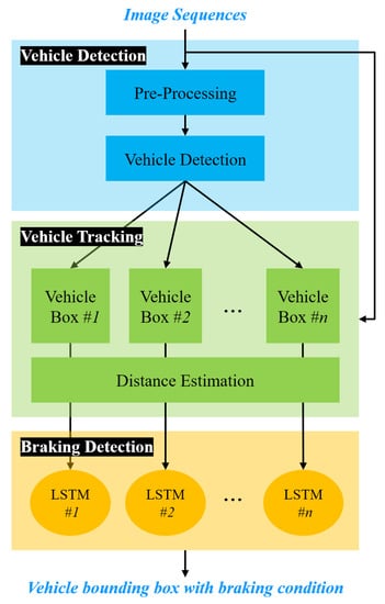
Figure 4.
Processing flow of the proposed method.
2.2. Vehicle Detection
In this step, features are extracted using a pre-trained deep learning model to detect vehicles driving in highway tunnels and learned using a YOLO v4 deep learning network. The structure of the convolutional neural network (CNN) used to detect vehicles in road tunnel images consists of various combinations of the convolution layer and pooling layer. CNNs were designed to process visual images more effectively by applying filtering techniques to artificial neural networks and have since been used in deep learning. Existing filtering techniques process images using fixed filters, but the basic concept of CNN is to automate learning so that each element of the filters expressed in a matrix is suitable for data processing. The algorithm applied for vehicle detection is an object detection algorithm through CNN-based feature extraction and YOLO v4 deep learning, and it is a one-stage detector model. The one-stage detector is a method of detecting objects by performing classification and localization simultaneously, calculating the probability that there is an object to be found for each grid cell of the convolution layer by looking at the image only once. Through this method, the speed can be improved compared to the two-stage detector, which considers accuracy to be more important [26]. The advantage of YOLO using this principle is that it is possible to calculate a single regression problem at a time. YOLO is structured in the same way that when the human eye sees a specific environment, it can identify the object it is looking for at once. As such, the structure of YOLO has the characteristic of rapidly detecting objects by using a single pipeline instead of the sliding window method or the complicated method of region proposal applied by other object detection methods [27,28]. YOLO is a convolution network structure that simultaneously calculates the location information and class probability of the bounding box of the object of interest in the image. As an advantage of this method, first, the detection speed is fast because the existing detection process has been changed into a regression problem. Second, since the entire image is observed when detecting an object, the shape and surrounding information of the object of interest are learned. Finally, since it learns the general characteristics of an object of interest, it shows relatively accurate detection performance even if an unspecified object is included in the training image.
YOLO v4 used in the proposed method can be calculated at once by predicting the position and probability of the vehicle in the input image as one regression. Figure 5 shows the processing flow of the vehicle detector using the YOLO v4 deep learning network. The YOLO v4 network structure for vehicle detection consists of three parts: backbone, neck, and head. The backbone of the YOLO v4 network extracts a feature map from the input image using a pre-trained convolution neural network. The neck part connects the backbone and the head and consists of a Spatial Pyramid Pooling (SPP) module and a Path Aggregation Network (PAN). The neck connects feature maps from different layers of the backbone network and sends them as inputs to the head part. The head processes aggregated functions and predicts bounding boxes, objectivity scores, and classification scores. The YOLO v4 network uses a first-stage object detector, such as YOLO v3 as the detection head.
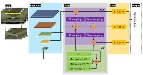
Figure 5.
Flow chart of vehicle detection step based on YOLO v4.
In this step, the Darknet-53 convolutional neural network of Cross Stage Partial (CSP) with robust features extraction capability of various scales was used as a backbone to improve the performance of vehicle detectors [29]. The backbone outputs five feature maps of different sizes, and the feature maps are fused at the neck of the YOLO v4 network. The convolution kernel size of each CSP module is set to 3 × 3 and the stride is set to 2 so that the module implements the down-sampling. A neck is inserted between the backbone and the output layer to help extract the characteristics of the fusion of various features in the YOLO v4 network. The YOLO v4 deep learning network used in this paper adopted an SPP and a PAN model. SPP and PAN modules are applied to the neck part to fuse low-level and high-level features. The SPP module in the neck part extracts the most representative feature maps by connecting the maximum pooling output of the low-resolution feature map. The most representative feature maps from the SPP model are fused with the high-resolution feature maps by using a PAN. The PAN module outputs the aggregated feature maps by combining the low-level and high-level features using the up-down sampling operations. The head part has three YOLO v3 detectors. The YOLO v4 outputs feature maps of the object to be detected [26,30]. In the YOLO v4 network, input data pass through a set of convolutional layers and max-pooling layers. By repeating this convolutional layer and max-pooling process, the input data are reduced in size while maintaining their characteristics. In this step, as a process of detecting vehicles from an image sequence acquired while driving in a highway tunnel, the image quality is relatively lower than that of a general road. In order to improve the image quality, a pre-processing of applying noise removal is performed.
2.3. Vehicle Tracking
This step tracks the detected vehicle regions in the next frame. Using Kalman filtering techniques to track detected vehicles, the position of the vehicle region detected in the previous frame is predicted in the next frame. It is assumed that the speed of the vehicle does not change rapidly while driving in a road tunnel. In addition, in the highway tunnel, vehicles drive in a predictable direction and drive at a constant speed while maintaining a constant distance. Therefore, the motion of the bounding box including the vehicle detected in each frame is estimated in the next frame using the Kalman filter. The Kalman filter predicts the position of the bounding box detected in the previous frame in the next frame and determines the possibility of detecting the bounding box in each frame. The Kalman filter is a filter that recursively processes input data including noise and can perform optimal statistical prediction of the current state [31]. The Kalman filter algorithm predicts an output value that minimizes the noise effect on the system output value by iteratively calculating the prediction and update [32]. The prediction refers to the prediction of the current state, and the update refers to the ability to make a more accurate prediction through the value including the observed measurement from the current state. The processing process of such a Kalman filter is shown in Figure 6.
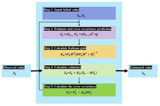
Figure 6.
Flow chart of vehicle detection step based on YOLO v4. The processing process of Kalman filter.
The process step by step in Figure 6 is as follows.
- step 1: Set the initial value of the estimated value x and the error covariance P.
- step 2: Calculate the estimated value and the predicted value of the covariance using the system model variables A and Q.
- step 3: Calculate the Kalman gain K using the predicted estimates and the system model variables H and R.
- step 4: Calculate the current estimate using the current input, the predicted estimate, and the Kalman gain.
- step 5: Recalculate the error covariance.
The position of the detected object is estimated by repeating steps 2 to 5. Prediction is the process of estimating how the previously estimated value changes. Looking at the calculation process of the Kalman filter, as shown in step 2 of Figure 6, the process of calculating the predicted value (k−1) and the error covariance () using the previously estimated value () and the error covariance () is performed. The calculation formula of the prediction process is constructed through system modeling and is a design value that determines the performance of the Kalman filter and can be changed by the designer. After the prediction process, the Kalman gain is calculated as in step 3 in the estimation process. The calculated Kalman gain is used for calculating the step 4 estimate and calculating the step 5 estimate error covariance. In the Kalman gain calculation formula of step 3, the matrix H and the substitution matrix are transform matrices for calculation, so they are simplified and expanded. Through the expanded formula, it can be seen that the Kalman gain () is the ratio of the error () of the estimate to the error(R) of the measured value. Therefore, when the measurement error is relatively large compared to the estimation error, the Kalman gain becomes small, and when the measurement error is relatively smaller than the estimation error, the Kalman gain increases. In the estimation value calculation formula of step 4, the Kalman gain () has a value of 0 to 1, and means the weight multiplied by the predicted value () and the observed value (). Since the Kalman filter is iteratively performed, the Kalman gain gradually decreases as the filter operates well and the reliability of the prediction value calculation increases, and a relatively high weight is given to the predicted value compared to the observed value. In step 2, the prediction system error variance value is used to calculate the prediction value, and in step 3 the Kalman gain calculation equation, the prediction system error variance value and the measurement error variance value are used. The predicted system error variance value is optimized with the Kalman gain calculated in step 5.
2.4. Distance Estimation
This step estimates the distance to the vehicle regions detected in a highway tunnel image. Estimating the distance to a vehicle driving ahead, such as an autonomous vehicle, is to prevent a collision by securing a safe distance. In particular, in highway tunnels, the driver’s field of view becomes very narrow, and the sense of distance between front-driving vehicles decreases due to the decrease in recognition of the actual speed of the vehicle and the decrease in visibility due to tunnel lights. Therefore, it is necessary to inform the driver of the distance from the vehicle in front while driving. Recently, the distance between vehicles is estimated using a laser or a Lidar sensor, but these sensors are exposed to the outside of a vehicle and malfunction due to contamination, etc. These sensors are easily damaged by minor vehicle collisions [22,25]. The CCD sensor has the advantage of being able to acquire visual information in an environment similar to the driver’s vision as it is attached to the interior window of the vehicle. In this step, we propose the distance estimation between vehicles using CCD sensors in highway tunnels. For distance estimation, the distance is estimated by transforming the two-dimensional space into a three-dimensional space using the inverse perspective mapping method applied in the previous research [25]. It is difficult to estimate the distance of the front vehicle relatively accurately in a highway tunnel during high-speed driving using a CCD sensor. More accurate distance estimation requires the help of additional sensor devices such as Lidar and laser. However, in our proposed method, the distance information is used as information to determine how close the distance to the vehicle being driven is rather than accurate distance estimation. Therefore, the distance error within about 5 m is ignored and the roughly detected distance from the vehicle driving ahead is divided into three levels: far, normal, and close. If the distance to the detected vehicle is more than 60 m, it is classified as far, 59–40 m is normal, and within 39 m is close. In order to project the 2D highway tunnel image acquired from the black-box CCD camera into a 3D space, it is necessary to acquire the parameters of the camera. To estimate the camera parameters, a camera calibration process is performed. Figure 7 shows the relationship between the 3D coordinates of the real world and the pixel coordinates projected into the corresponding 2D space of the image captured by the calibrated camera.

Figure 7.
Overview of coordinate transformations for camera calibration.
The camera calibration estimates the two types of parameters as shown in Figure 7. Accurate coordinate conversion between the acquired image and the actual vehicle is required to estimate the internal and external parameters of the camera. To estimate the camera parameters, we use a checkerboard pattern board that knows the size information in the dictionary. Figure 8 shows the relative position of the camera and the checkboard pattern for estimating the camera external parameters. Figure 8a shows the relative position of the pattern board from the camera’s point of view, and Figure 8b shows the relative position of the camera from the pattern board’s point of view.
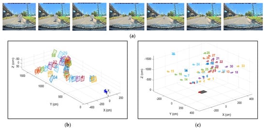
Figure 8.
Visualization results of intrinsic/extrinsic parameters of the camera according to the position of the pattern boards. (a) Pattern board images, (b) Extrinsic paramters visualization, (c) Extrinsic paramter visualization.
As shown in Figure 8, the camera parameters (camera intrusion factors, distortion coefficients, and camera extrinsic) are estimated based on the pattern board. The actual coordinates in the 3D space are defined from the pattern board image acquired with the camera using a pattern board of a known size in advance. Pattern board images are acquired from various views, and corresponding corner points are detected by projecting 3D points from different pattern board images into 2D pixel coordinates. Camera parameters are detected through a re-projection process for matching between 2D pixel coordinates and 3D pointers. The optimal camera parameters that reduce the estimation error of the camera parameters are derived while the re-projection process is performed using a plurality of pattern board images.
The proposed method ignores the distortion coefficient of the camera lens because there is little distortion in the image data obtained from the black-box CCD camera. Moreover, the tilt of the black-box camera installed in the vehicle is considered horizontal and defined as 0. The height of the camera is the same as the height of the vehicle window because the black-box camera is installed on the vehicle window. Figure 9 is a bird-view image generated by projecting the input image into a 3D space. The bird-view image is converted by projecting the 2D coordinates of the image acquired with the camera into the 3D real-world space. Therefore, the detected distance to the vehicle is the coordinates of the z-axis converted from the 2D coordinates of the lower end of the bounding box into the 3D space.

Figure 9.
Results of the highway tunnel image projection into bird-view. (a) Highway tunnel image, (b) Brid-view image with distances.
2.5. Vehicle Brake Lights Detection
This step detects whether the vehicle’s brake lights are turned on. In research [16,17,33] detecting whether vehicle brake lights are turned on, a detection method was proposed based on the change in brightness and color of vehicle brake lights while driving. Their research is to detect vehicle areas from a single image and analyze the degree of brightness and color change of brake lights. In general, vehicle braking operation for vehicle deceleration during road driving is a continuous operation for a certain period of time. It is necessary to determine whether the vehicle brake is operated for a certain period of time, rather than determining whether the brake is operated only for a short moment. Previous research has proposed a method to determine whether the change in color or brightness of vehicle brake lights in a single image exceeds a threshold [13,14]. However, if it is determined whether or not the vehicle brake lights are turned on only in a single image, the following problems may occur. For highway tunnel driving, it is generally guided to turn on the vehicle’s headlights or taillights, and in some countries, it is mandatory by law to turn on the headlights so that the driving vehicles can be identified. In addition, recently released vehicles are equipped with a function to automatically turn on the headlights in dark road tunnels based on the illuminance sensor. Therefore, when the vehicle headlights or taillights are turned on, there is a problem in determining that the vehicle is braking because the brake lights are also turned on. In order to discriminate relatively accurately, it is necessary to analyze the color change of vehicle brake lights according to the temporal change rather than a single image. Therefore, this step detects whether vehicle brake lights are turned on using the LSTM network based on the spatiotemporal color change of the vehicle areas acquired in the previous step. Additionally, the distance information obtained in the distance estimation step is also used to detect whether vehicle brake lights are turned on. As shown in Figure 10, a total of nine frames are used for 3 s for LSTM network training, and the next frame is selected at an interval of 2 s for the next frame selection. Therefore, the vehicle bounding boxes detected in each image are input to the CNN to extract features. The proposed method uses the ResNet-18 convolutional neural network as a pre-trained network for feature extraction [34]. Then, the extracted features and the distance obtained in the distance estimation step are used as feature vectors for LSTM network learning. The LSTM network is used to extract temporal feature vectors to bounding boxes detected in continuous images. The detected vehicle regions are normalized to 224 × 224 pixels size for input in the ResNet-18 network. The detected regions are transformed into a sequence of feature vectors, where the feature vectors are the output of the activation function on the last pooling layer (pool5) of the ResNet-18 network. The LSTM network determines whether the detected vehicle brake lights are turned on by analyzing the changes in the color and distance of the detected vehicle bounding-box regions in the image sequences.
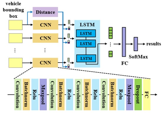
Figure 10.
Architecture of the proposed method for the front vehicle brake lights detection.
LSTM is a kind of recurrent neural network (RNN) that can learn long-term dependencies between time steps of time series sequence data. Unlike CNNs, LSTMs utilize memory cells that can remember the state of the network between predictions. The core components of the LSTM network are the sequence input layer and the LSTM layer. The sequence input layer inputs time series data to the network. The LSTM layer learns long-term dependencies between sequence data time steps over time. The structure of LSTM is shown in Figure 11.
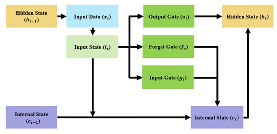
Figure 11.
Structure of LSTM network.
The memory cell first calculates the input state (i) from the input data (x) in the current time step (t) and the hidden state (h) in the previous step (t − 1) (Equation (1)). Then, the input gate (g) of Equation (2), the forget gate (f) of Equation (3), and the output gate (o) of Equation (4) are calculated through the input state. Using the calculated values and the internal state value in the previous time stage (t − 1), the internal state (c) of the current time stage (t) is updated as shown in Equation (5). As in Equation (6), the hidden state (h) of the current step to be used in the next step (t + 1) is calculated, and it has the advantage of being able to make a longer-term prediction by considering short-term information and old past information (Figure 11).
Here, σ: activation function, : weight for input data in input state, : weight for hidden state in input state, : weight for input state in input gate, : weight for input state in forget gate, : the weight for the input state in the output gate, and ⊙ is the wise-element product.
In this step, the vehicle brake lights turn on and off; image sequences in the vehicle area detected in the highway tunnel were used for LSTM learning. Excluding the image sequences in which brake lights are turned on due to the lighting of vehicle headlights in the highway tunnel, image sequences of vehicle brake lights in a situation where the distance between vehicles is getting closer due to the actual vehicle’s brake operation were used for LSTM learning. The LSTM network is capable of classifying the feature vector represented by an image sequence in which the vehicle brake light is turned on as the distance between vehicles approaches is created in the proposed method. The LSTM neural network architecture consists of a sequence input layer whose input size is equal to the feature dimension of the feature vector, a bidirectional LSTM(BiLSTM) layer with 1000 hidden units followed by a dropout layer, and a fully connected layer, soft max layer, and classification layer that outputs one label for each image sequence [35].
The input of the LSTM is the last pooling layer feature of the ResNet-18 convolutional neural network and the distance obtained in the distance estimation step. Therefore, the input size of the LSTM is F × C, and F is 513, which is the number of features (output size of pooling layer + distance value), and C is 40, which is the number of image sequence frames. The LSTM architecture consists of a sequence input layer whose input size is the same as the feature dimension of the feature vector, a BiLSTM layer with 1000 hidden units followed by a dropout layer, a fully connected layer with an output size of 1, and a softmax layer and a classification layer. The training options for the LSTM were set to the output mode option of the BiLSTM as last, dropout to 0.5, mini-batch to 16, initial learning rate to 0.001, and a gradient threshold to 2. A sequence that is much longer than a typical sequence in the network can cause a large amount of padding to be applied during the training process. Thus, too much padding may degrade classification accuracy. In the proposed method, the length of the highway tunnel image sequence used for LSTM training is rarely more than 40 frames, so training sequences with more than 40 time steps are removed to improve classification accuracy. In the proposed method, highway tunnel images used for LSTM training acquire 3 frames per second, and features are extracted while moving the frame by 3 s and used for LSTM learning.
3. Experimental Results
To experiment with the proposed method, tunnel image sequences were obtained from two different models of vehicle black-box CCD cameras in a highway tunnel in Korea (vehicle-black-box models: Find View CR-500HD, X3000New). The cameras are installed in the top center of the windshield inside the research vehicles. The size of the acquired image is HD level, it is a 24-bit color frame of 1920 × 1080 and 2560 × 1440 pixels, and the image was acquired at 30 frames per second. Due to the characteristics of highway tunnels, the illumination is lower than that of general roads, so to compensate for this, commercial black-box products are equipped with functions such as brightness correction and High Dynamic Range (HDR). In the proposed method, image sequences were obtained by disabling the brightness correction and HDR function to minimize the constant brightness and color change of the image. In the proposed method, it was processed at 3 frames per second, and only the central region was extracted from the acquired tunnel image. Although it is necessary to reduce the HD-level image for real-time processing, when the image is reduced, the area of the vehicle driving ahead is also reduced, making it difficult to detect a vehicle. Accordingly, the proposed method is processed only in the center ROI region except for regions unnecessary for the input image, that is, regions on the top, bottom, left, and right sides of the image. The vehicle hood and road belonging to the lower part of the image, the tunnel ceiling belonging to the upper part, and the tunnel walls belonging to the left and right parts were excluded from the processing step as unnecessary regions for vehicle detection. Therefore, the size of the region in which the processing is performed is 1920 × 1080 pixels and the size of the black-box image processed is 1320 × 680 pixels. Learning images for vehicle detection are highway tunnel images and are not affected by image acquisition time and weather. However, vehicle detection in the highway tunnel entry and exit area was impossible due to rapid changes in illumination, which was excluded in our method due to the limitations of CCD cameras. The PC environment used to experiment with the proposed method utilized Matlab in Windows 10OS (Intel Hexa Core i9-12900@3.2 GHz 16-core processor, 64 GB RAM size, 3080ti GPU, and 4TB SSD). Figure 12 is an image sequence while driving in a highway tunnel used for learning in the proposed method. There were 12 highway tunnels obtained in the experiment, and 189 videos were collected while driving.
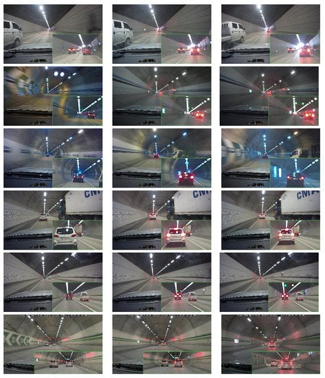
Figure 12.
Vehicle image sequences in the highway tunnel used for training in the proposed method.
To evaluate the performance of the proposed method, the experimental measurement metrics used Intersection Over Union (IoU), precision, recall, and mean average precision (mAP), and are calculated with Equation (7). Experimental results show that if the IoU value is 0.5 or higher, it is considered a success in detection and tracking.
Here, the IoU is a measure to quantify the overlapping level between the prediction and ground truth bounding boxes, which is defined as follows. The prediction is considered correct if IoU is above a certain threshold. Meanwhile, precision and recall serve as the basic metrics for object detection, and the F1-score is the weighted average of precision and recall as follows. TP (true positives) means positive predictions that match with the ground truth. FP (false positive) means positive predictions that do not match with ground truth. FN (false negative) means negative predictions that do not match with ground truth. mAP is the global score as the mean of the average precision for each class. Precision-recall curves illustrate the tradeoff between precision and recall for different thresholds. Average precision (AP) stands for the area under the curve, which measures the detection performance for a single class [19].
3.1. Results of Vehicle Detection
The ROI of the images acquired from the highway tunnel was normalized to a size of 608 × 608 pixels, and the learning algorithm used for vehicle detection was the YOLO v4 deep learning network. The training parameters applied to the YOLO v4 network were set to 16 for miniBachsize, 0.001 for the initial learning rate, and the Adam solver for 100 epochs. A median filter with a 3 × 3 filter size was applied to remove noise from the highway tunnel images. In order to detect vehicles in highway tunnel images using the YOLO v4 network, we first construct a dataset for training, validation and testing of the network.
The proposed method constructs a training dataset for training, validation, and testing of the YOLO v4 vehicle detection network. To improve the YOLO v4 network efficiency, we perform data augmentation on the training dataset and compute anchor boxes on the training data to be used to train the YOLO v4 vehicle detection network. Anchor boxes are a set of predefined bounding boxes with certain scales and aspect ratios. Figure 13 shows the horizontal/vertical ratio and size of the vehicle area shown in the training image and the mean IoU results compared to the number of Anchor boxes for training the YOLO v4 vehicle detection network. In Figure 13a, a k-means clustering algorithm is used to select anchor boxes with optimal Mean IoU. Figure 13b shows the results of Mean IoU according to the number of k-means clustering. As shown in Figure 13b, the clustering number k of the k-means clustering algorithm with the optimal Mean IoU is 23, but a total of 12 anchor boxes were selected due to too many clustering calculations.
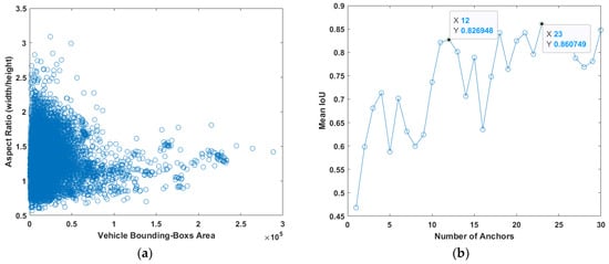
Figure 13.
Results of estimating the number of anchor boxes in the training data. (a) Aspect ratio and vehicle bounding boxes area; (b) Mean IOU and number of anchor boxes.
The deep learning methods used to compare the accuracy of vehicle detection were compared with SSD [36], Faster R-CNN [27], YOLO v2 [37], and YOLO v3 [38]. Moreover, YOLO v2 and v3 used the value of the active-40 rluelayer as features in the pre-learning model of Resnet-50. The training data are augmented by random horizontal flipping and random x- and y-axis scaling. The training data augmented for learning, validation, and testing of the deep learning network were divided at a ratio of 6:2:2 and the experiment was conducted. Table 1 shows the results of vehicle detection according to the deep learning networks in the highway tunnel images. As a result of the experiment, the model using the YOLO v4 deep learning network for training showed relatively high vehicle detection performance. Figure 14 shows the results of detecting vehicles from the highway tunnels. The highway tunnels generally have a problem of low image quality due to low illuminance and vehicle exhaust gas. For this reason, the vehicle region located far away from the tunnel image is small and cannot be detected.

Table 1.
Vehicle detection results using different vehicle detection models.
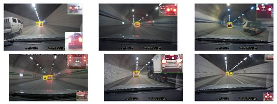
Figure 14.
Results of vehicle detection in the highway tunnels.
3.2. Results of Vehicle Tracking and Distance Estimation
In the vehicle tracking step, the location of the vehicle was estimated in the image sequence by using the Kalman filter on the vehicle regions detected in the vehicle detection step. To evaluate the performance of the vehicle tracking step, the results of labeling the vehicle region in highway tunnel image sequences and the location detected through the vehicle tracking step were compared. The IoU is used to compare the results of labeling the vehicle location using the ground-truth method and the vehicle location detected through the vehicle tracking step with the Kalman filter. Figure 15 compares the location of the vehicle labeled with the ground-truth method in the highway tunnel and the location of the vehicle estimated through the Kalman filter. Experiments show that vehicle detection fails when some vehicle area overlaps with other vehicles, but vehicle detection is possible by applying a Kalman filter to tracking.
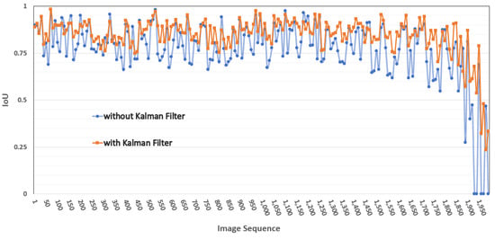
Figure 15.
Comparison of vehicle detection accuracy IoU according to vehicle tracking processing.
To evaluate the performance of the vehicle distance estimation, the distance estimation results were compared in the experimental road environment. In the experimental environment, the difference between the actual distance from the vehicle in front and the distance estimated through the proposed method was compared. However, the proposed method is to estimate the approximate distance from the detected vehicle rather than the accurate distance estimation, and if the distance estimation error is less than 5 m, it was evaluated as the correct estimation. The distance to the detected vehicle was calculated from the center point of the bottom of the vehicle’s bounding box. Figure 16 is the results of projecting the input tunnel images into the three-dimensional space as a bird-view image, and the results of displaying the estimated distance from the detected vehicle bounding box. The distance measurement of a driving vehicle was compared with distance information using a laser rangefinder and distance information was estimated through the proposed method. As a result of the experiment, the distance estimation accuracy of detected vehicles was presented at about 94%.
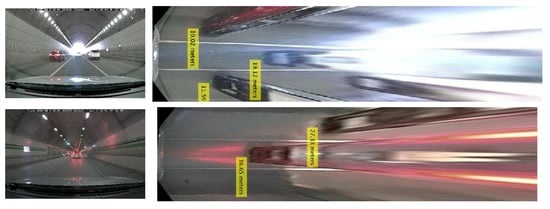
Figure 16.
Results of 3D projection of highway tunnel image and vehicle distance estimation.
3.3. Results of Vehicle Brake Lights Turn on Detection
The LSTM network was used to detect whether the vehicle brake lights are turned on or not in the vehicle bounding box acquired through the vehicle detection and tracking step. For training, testing, and verification of the LSTM network, training data were classified at a ratio of 6:2:2 and the number of hidden layers was determined through performance comparison according to the number of hidden layers of the LSTM network. Moreover, the epoch, minibatchsize, and initial training parameters of the LSTM network were also determined through experiments. Figure 17 shows the results of vehicle detection, distance estimation, and detection of whether the brake lights are turned on in the highway tunnel image. Figure 17b shows the detection and enlargement of the vehicles included in the ROI area in the vehicle detection step. Moreover, Figure 17c is a result of determining the estimated distance of the detected vehicle areas and whether the brake lights are turned on.
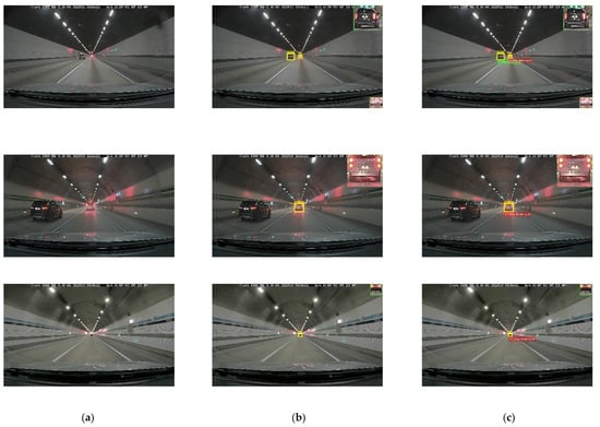
Figure 17.
Results of vehicle detection, distance estimation, and brake lights lighting detection applying the proposed method. (a) original image; (b) vehicle detection; (c) vehicle distance estimation and brake lights lighting.
As a result of experimenting with the proposed method in various highway tunnels in Table 2, the average accuracy of detecting whether the vehicle brake lights are turned on or not was presented with an accuracy of about 90.6%. To evaluate the performance of detecting whether vehicle brake lights are turned on in a highway tunnel using the proposed method, it was compared with the SVM classifier method using brightness and Lab color information [16] and the proposed method using the RGB color difference threshold method [18]. For performance comparison, only the determination of whether the brake lights are turned on in the areas where the vehicle is detected in the highway tunnel image was evaluated. As a result of the experiment, the lighting of the vehicle taillights in a dark highway tunnel was mistakenly recognized as the lighting of the brake lights. In the proposed method, robust recognition results are presented by utilizing the estimated distance information of vehicles in multiple image frames. However, due to the characteristics of highway tunnels and high speed travel, there is a limitation in that the detection rate is slightly lowered due to the small area of vehicles that travel from a long distance. In addition, the high-brightness LED brake lights of a vehicle have a problem of erroneous detection due to the lighting, and due to the brake operation even when the headlight or taillight is turned on instead of the vehicle braking due to the light leak phenomenon. In future research, we will study ways to minimize errors in the learning process by acquiring more road tunnel driving images.

Table 2.
Results of detection of vehicle brake lights turn on.
4. Conclusions and Future Works
In this paper, we propose a method to detect whether the brake lights of a front vehicle are turned on due to the deceleration of a vehicle in front, in a highway tunnel. The proposed method uses the LSTM deep learning network that can learn long-term dependencies between highway tunnel image sequences to detect whether a driving vehicle’s brake lights are turned on. Using the LSTM network, it detects whether the vehicle brake lights are turned on or off by using vehicle detection, tracking, distance estimation, and temporal continuity information of detected and tracked vehicle regions. In order to detect vehicles in highway tunnels, the YOLO v4 vehicle detector was created, and strong results were presented in an environment where the illuminance was not constant and it was difficult to detect vehicles due to tunnel air pollution. The detected vehicle bounding boxes can be tracked robustly even if overlapping occurs by other driving vehicles by estimating the position in the next frame using a Kalman filter. The distances were estimated from the bird-view image by projecting the detected and tracked vehicle bounding boxes into the 3D real-world coordinate space. The LSTM network, which learns the vehicle bounding boxes detected in the vehicle detection step and distance information calculated in the distance estimation step, detects whether the vehicle brake lights are turned on or not. As a result of experimenting with the proposed method in the highway tunnel, the detection results of relatively high vehicle brake light lighting were presented. However, there have been problems in that detection of a vehicle fails due to the overlapping of driving vehicles or erroneous detection occurs when only one of the vehicle brake lights is turned on. Therefore, in order to overcome the problems, we will collect more diverse training data and develop a robust deep-learning algorithm.
The proposed method can be applied to a system that can prevent a collision with a vehicle ahead in a highway tunnel in advance. Driving a vehicle for a long time can reduce the ability to recognize objects and the driving environment by increasing the driver’s fatigue. Therefore, a study on driver fatigue monitoring due to long-time driving work is also an important part of vehicle safety support technology. The results of this study will be applied to a vehicle black box and applied to a warning system for securing a safe distance based on the detection of a driving vehicle and distance estimation information that the driver did not recognize on the highway tunnel. Furthermore, future research will conduct research on the development of an integrated vehicle safety monitoring system that combines driver face analysis and electrocardiogram information to monitor driver fatigue.
Funding
This work was supported by the National Research Foundation of Korea (NRF) grant funded by the Korea government (MSIT) (NRF-2020R1F1A106890011).
Institutional Review Board Statement
Not applicable.
Informed Consent Statement
Not applicable.
Data Availability Statement
Not applicable.
Conflicts of Interest
The author declares no conflict of interest.
References
- Parekh, D.; Poddar, N.; Rajpurkar, A.; Chahal, M.; Kumar, N.; Joshi, G.P.; Cho, W. A Review on Autonomous Vehicles: Progress, Methods and Challenges. Electronics 2022, 11, 2162. [Google Scholar] [CrossRef]
- Leon, P.; Patryk, S.; Mateusz, Z. Research Scenarios of Autonomous Vehicles, the Sensors and Measurement Systems Used in Experiments. Sensors 2022, 22, 6586. [Google Scholar]
- Muhammad, A.; Sitti, A.H.; Othman, C.P. Autonomous Vehicles in Mixed Traffic Conditions—A Bibliometric Analysis. Sustainability 2022, 14, 10743. [Google Scholar]
- International Traffic Safety Data and Analysis Group. Available online: http://cemt.org/IRTAD (accessed on 28 September 2022).
- Traffic Accident Analysis System of the Korea Road Traffic Authority. Available online: https://taas.koroad.or.kr/ (accessed on 28 September 2022).
- Shy, B. Overview of traffic safety aspects and design in road tunnels. IATSS Res. 2016, 40, 35–46. [Google Scholar]
- Qiang, M.; Xiaobo, Q. Estimation of rear-end vehicle crash frequencies in urban road tunnels. Accid. Anal. Prev. 2012, 48, 254–263. [Google Scholar]
- Kerstin, L. Road Safety in Tunnels. Transp. Res. Rec. J. Transp. Res. Board 2000, 1740, 170–174. [Google Scholar]
- Mashimo, H. State of the road tunnel safety technology in Japan. Tunn. Undergr. Space Technol. 2002, 17, 145–152. [Google Scholar] [CrossRef]
- Qiuping, W.; Peng, Z.; Yujian, Z.; Xiabing, Y. Spatialtemporal Characteristics of Tunnel Traffic Accidents in China from 2001 to Present. Adv. Civ. Eng. 2019, 2019, 4536414. [Google Scholar]
- Cheongyang Tunnel in Korea. Available online: http://www.ilyoseoul.co.kr/news/articleView.html?idxno=232633 (accessed on 28 September 2022).
- Installation of Accident Prevention Broadcasting System in Yangyang Tunnel in Korea. Available online: https://m.dnews.co.kr/m_home/view.jsp?idxno=201707061410472090956 (accessed on 28 September 2022).
- Zhiyong, C.; Shao, W.Y.; Hsin, M.T. A Vision-Based Hierarchical Framework for Autonomous Front-Vehicle Taillights Detection and Signal Recognition. In Proceedings of the 2015 IEEE 18th International Conference on Intelligent Transportation Systems, Gran Canaria, Spain, 15–18 September 2015; pp. 931–937. [Google Scholar]
- Jesse, P.; Risto, O.; Klaus, K.; Jari, V.; Kari, T. Brake Light Detection Algorithm for Predictive Braking. Appl. Sci. 2022, 12, 2804. [Google Scholar]
- Hochreiter, S.; Schmidhuber, J. Long Short-Term Memory. Neural Comput. 1997, 9, 1735–1780. [Google Scholar] [CrossRef]
- Dario, N.; Giulio, P.; Sergio, M.S. A Collision Warning Oriented Brake Lights Detection and Classification Algorithm Based on a Mono Camera Sensor. In Proceedings of the 2019 IEEE Intelligent Transportation Systems Conference (ITSC), Auckland, New Zealand, 27–30 October 2019; pp. 319–324. [Google Scholar]
- Wang, J.G.; Zhou, L.; Pan, Y.; Lee, S.; Song, Z.; Han, B.S.; Saputra, V.B. Appearance-based Brake-Lights recognition using deep learning and vehicle detection. In Proceedings of the 2016 IEEE Intelligent Vehicles Symposium (IV), Gothenburg, Sweden, 19–22 June 2016; pp. 815–820. [Google Scholar]
- Liu, W.; Bao, H.; Zhang, J.; Xu, C. Vision-Based Method for Forward Vehicle Brake Lights Recognition. Int. J. Signal Process. Image Process. Pattern Recognit. 2015, 8, 167–180. [Google Scholar] [CrossRef]
- Li, Q.; Garg, S.; Nie, J.; Li, X.; Liu, R.W.; Cao, Z.; Hossain, M.S. A Highly Efficient Vehicle Taillight Detection Approach Based on Deep Learning. IEEE Trans. Intell. Transp. Syst. 2021, 22, 4716–4726. [Google Scholar] [CrossRef]
- Panagiotou, D.K.; Dounis, A.I. Comparison of Hospital Building’s Energy Consumption Prediction Using Artificial Neural Networks, ANFIS, and LSTM Network. Energies 2022, 15, 6453. [Google Scholar] [CrossRef]
- Amerikanos, P.; Maglogiannis, I. Image Analysis in Digital Pathology Utilizing Machine Learning and Deep Neural Networks. J. Pers. Med. 2022, 12, 1444. [Google Scholar] [CrossRef]
- Kim, J.B. Vehicle Detection Using Deep Learning Technique in Tunnel Road Environments. Symmetry 2020, 12, 2012. [Google Scholar] [CrossRef]
- Chen, X.; Jia, Y.; Tong, X.; Li, Z. Research on Pedestrian Detection and DeepSort Tracking in Front of Intelligent Vehicle Based on Deep Learning. Sustainability 2022, 14, 9281. [Google Scholar] [CrossRef]
- Yang, W.; Fang, B.; Tang, Y.Y. Fast and Accurate Vanishing Point Detection and Its Application in Inverse Perspective Mapping of Structured Road. IEEE Trans. Syst. Man Cybern. Syst. 2018, 48, 755–766. [Google Scholar] [CrossRef]
- Kim, J.B. Efficient Vehicle Detection and Distance Estimation Based on Aggregated Channel Features and Inverse Perspective Mapping from a Single Camera. Symmetry 2019, 11, 1205. [Google Scholar] [CrossRef]
- Redmon, J.; Divvala, S.; Girshick, R.; Farhadi, A. You Only Look Once: Unified, Real-Time Object Detection. In Proceedings of the IEEE Conference on Computer Vision and Pattern Recognition (CVPR), Las Vegas, NV, USA, 27–30 June 2016; pp. 779–788. [Google Scholar]
- Ren, S.; He, K.; Girshick, R.; Sun, J. Faster R-CNN: Towards Real-Time Object Detection with Region Proposal Networks. IEEE Trans. PAMI 2017, 39, 1137–1149. [Google Scholar] [CrossRef]
- Strbac, B.; Gostovic, M.; Lukac, Z.; Samardzija, D. YOLO Multi-Camera Object Detection and Distance Estimation. In Proceedings of the 2020 Zooming Innovation in Consumer Technologies Conference (ZINC), Novi Sad, Serbia, 26–27 May 2020; pp. 26–30. [Google Scholar]
- Redmon, J. Darknet: Open Source Neural Networks in C. Available online: https://pjreddie.com/darknet (accessed on 28 September 2022).
- Bochkovskiy, A.; Wang, C.Y.; Liao, H.M. YOLOv4: Optimal Speed and Accuracy of Object Detection. arXiv 2020, arXiv:2004.10934. [Google Scholar]
- Brown, R.G.; Hwang, P.Y.C. Introduction to Random Signals and Applied Kalman Filtering with Matlab Exercises, 4th ed.; Wiley: Hoboken, NJ, USA, 2012. [Google Scholar]
- Peterfreund, N. Robust tracking of position and velocity with Kalman snakes. IEEE Trans. PAMI 1999, 21, 564–569. [Google Scholar] [CrossRef]
- Cabani, I.; Toulminet, G.; Bensrhair, A. Color-based detection of vehicle lights. In Proceedings of the IEEE Proceedings. Intelligent Vehicles Symposium, Las Vegas, NV, USA, 6–8 June 2005; pp. 278–283. [Google Scholar]
- He, K.; Zhang, X.; Ren, S.; Sun, J. Deep Residual Learning for Image Recognition. In Proceedings of the IEEE Conference on Computer Vision and Pattern Recognition (CVPR), Las Vegas, NV, USA, 27–30 June 2016; pp. 770–778. [Google Scholar]
- He, K.; Zhang, X.; Ren, S.; Sun, J. Delving Deep into Rectifiers: Surpassing Human-Level Performance on ImageNet Classification. In Proceedings of the IEEE International Conference on Computer Vision, Santiago, Chile, 7–13 December 2015; pp. 1026–1034. [Google Scholar]
- Liu, W.; Anguelov, D.; Erhan, D.; Szegedy, C.; Reed, S.; Fu, C.Y.; Berg, A.C. SSD: Single shot multibox detector. Proc. ECCV 2016, 9905, 21–37. [Google Scholar]
- Redmon, J.; Farhadi, A. YOLO9000: Better, Faster, Stronger. In Proceedings of the Proceedings of the IEEE Conference on Computer Vision and Pattern Recognition, Honolulu, HI, USA, 21–26 July 2017; pp. 6517–6525. [Google Scholar]
- Redmon, J.; Farhadi, A. YOLOv3: An Incremental Improvement. arXiv 2018, arXiv:1804.02767. [Google Scholar]
Publisher’s Note: MDPI stays neutral with regard to jurisdictional claims in published maps and institutional affiliations. |
© 2022 by the author. Licensee MDPI, Basel, Switzerland. This article is an open access article distributed under the terms and conditions of the Creative Commons Attribution (CC BY) license (https://creativecommons.org/licenses/by/4.0/).