Abstract
Recently, wet blast cleaning of paint has attracted attention in remanufacturing processes, owing to its high efficiency and environmental friendliness. However, studies of removal mechanism have rarely considered the properties of abrasive particles; thus, there is insufficient theoretical guidance on the process optimization, resulting in energy waste during the cleaning process. Therefore, the mechanism in wet blast cleaning of paint was researched in this study, which focused on the effects of abrasive particle shape and size on mechanism. The results indicate that the removal mechanisms of angular and spherical abrasive particles are significantly different, and that of angular abrasive particles is not affected by the particle size, whereas that of spherical abrasive particles is significantly affected. The main removal mechanism for all angular abrasive particles is brittle fracture caused by large impact stresses. For large spherical abrasive particles (≥60-mesh), the main mechanism is brittle fracture due to the intersection of longitudinal-through fatigue cracks and interface cracks, and for small spherical abrasive particles (≤80-mesh), it is brittle fracture due to fatigue cracks and impact cracks. This study provides good insight into abrasive particles and serves as a good basis for exploring the process parameters for wet blast cleaning.
1. Introduction
Remanufacturing end-of-life products can greatly reduce energy consumption in production processes and environmental pollution, which is an important technique in line with sustainable manufacturing [1,2]. The remanufacturing process includes disassembling, cleaning, inspecting, repairing, replacing, and reassembling [3]. Among them, cleaning plays a very important role in remanufacturing processes. It involves the removal of contaminants from the interior or surfaces of a part to achieve a certain level of cleanliness and allows subsequent remanufacturing processes to proceed smoothly [4,5]. The effectiveness of the cleaning directly affects the subsequent inspection and restoration process. Paint, as a widely used industrial antirust product, adheres to the surface of the workpiece and is a type of dirt that must be cleaned in remanufacturing cleaning [6].
Various cleaning techniques have been developed to remove paint. The laser is a high-energy beam. When it hits the paint surface, the paint is quickly removed due to a heat effect, thermal stress effect, vaporization, and ionization effects [7,8]. Therefore, it is very efficient, but its cost is high and does not facilitate the cleaning of the paint in the corners. In molten salt cleaning, the workpiece is completely immersed in the molten salt solution, which can achieve complete cleaning [9,10]. The paint is decomposed and peeled off due to chemical reactions, but it produces toxic gases and pollutes the environment [11]. Water jet cleaning technology uses the impact of high-pressure water jets to remove paint [12,13]. It uses pure water as the cleaning medium; thus, it does not pollute the environment, but it is somewhat dangerous due to the high pressure. Dry blasting cleaning technology uses solid abrasive particles as the cleaning medium, using compressed gas to accelerate the abrasive particles, then the high-speed abrasive particles impact the paint surface to achieve removal [14]. It cleans efficiently but causes serious dust pollution [15]. Wet blast cleaning technology is an improved technology that combines water jet and dry blasting cleaning. Cleaning is achieved by spraying a jet of mixed abrasive particles and water onto the surface of the object [16]. It not only retains the high efficiency of dry blasting, but also uses water to solve dust pollution; hence, it has the advantages of high efficiency and low environmental pollution [17]. Therefore, it is in line with the concept of remanufacturing and has been applied and studied in remanufacturing cleaning.
Wu et al. optimized the parameters of pressure, stand-off distance, traverse rate, and cleaning times for cleaning efficiency and reported that traverse rate has a significant influence and provided the optimal process parameters based on the cleaning efficiency [16]. Xiong et al. optimized the process parameters by orthogonal experiments and reported that the most significant factor on cleaning capacity was water pressure, followed by abrasive particle feed-rate condition and stand-off distance [17]. Further, they reported that paint removal was caused by the combined impact of abrasive particles and water, where the impact of abrasive particles was dominant [18].
However, the mechanism of coating removal by abrasive particles is complex, and many scholars have made great efforts to study how abrasive particles act on paint during the paint removal process.
Papini and Spelt studied the removal of organic coatings by particle impact and reported that high- and low-interfacial-strength coatings were removed by mechanical erosion and delamination, respectively [19,20]. Further, they developed a theoretical model for the buckling and delamination of organic coatings due to particle impact [21,22]. Djurovic et al. studied the erosion of polyurethane topcoats and epoxy primers on four substrates using starch media blasting and reported that the urethane topcoat was removed cumulatively by chipping [23]. Zouari and Touratier reported that the impact of the particles generated shear and radial stress, leading to delamination and buckling of the paint, respectively [24]. Dong proposed a three-dimensional (3D) crack-extension model, which revealed that crack extension and the propagation of stress waves are the main reasons for paint removal [25]. Liu Y et al. reported that automotive coatings exhibited brittle fracture behavior when impacted by spherical steel particles at different angles [26].
In addition, the abrasive particles were often inconsistent, and they usually had different properties, especially in shape and size. These properties can significantly affect the erosion mechanism of the particles [27]. The effects of the shape of abrasive particles on erosion characteristics have been investigated. Naveed et al. used SiO2 particles to erode ductile (Ti-6Al-4V) and brittle materials (TiN) and found that the particle shape influences the wear mechanism of both materials [28]. Ning et al. investigated the effects of particle shape on the particle erosion behavior of EB-PVD TBCs using a finite element method and found that the shape of the erosion particles affects the maximum erosion depth, rebound velocity, and maximum residual stress at the same initial kinetic energy [29]. Mohseni-Mofidi et al. simulated the effects of particle shapes on erosion behavior and reported that particles with large angularity and small aspect ratios had more severe erosion [30]. The effects of abrasive particle size on the erosion characteristics of particles have also been investigated. Abouel-Kasem used SiO2 mortars of different sizes to erode UNS G5117 steel, and large particles removed material mainly by micro-plowing, whereas small particles removed material mainly by extrusion [31]. Nguyen et al. investigated the erosion characteristics of stainless steel eroded by multiphase flow (water and sand) through experiments and numerical simulations. They found that large particles dig deeper into the specimen surface, causing the erosion profile to transition from a “W” to a “U” shape [32]. Although the properties of abrasive particles have effects on the mechanism, there are insufficient studies on the effects of abrasive particle properties on the wet blast cleaning mechanism.
In this study, we focused on the effects of abrasive particle properties on the removal mechanism. The cleaning progresses of different abrasive particles were discussed, and the effects of abrasive particles shape and size on the removal mechanism were reported. These results provide a good basis for the study of process parameters and further development of remanufacturing cleaning.
2. Materials and Methods
2.1. Materials
2.1.1. Specimen Preparation
ADC12 aluminum alloy specimens (100 mm × 100 mm × 10 mm) were used. To ensure firm attachment of paint to the specimens, they were pretreated by dry sandblasting to increase the surface roughness. The parameters for the dry sandblasting are listed in Table 1.

Table 1.
Dry sandblasting pretreatment parameters.
Acrylic one-component solvent-based paint, which is widely used in the industrial field, was used in this study. The spraying process was repeated thrice at 30-minute intervals. After painting, the specimens were dried naturally for 30 days. The natural condition meant that temperature, humidity, and other characteristics varied with the weather, which made the specimen closer to the actual working conditions. Then, a coating thickness gauge was used to measure the thickness of the paint film, which was approximately 150 μm.
2.1.2. Abrasive Particles
As shown in Figure 1, the angular and spherical abrasive particles used in this study were brown corundum and brown corundum ball abrasive particles, respectively. Brown corundum abrasive particles are angular particles with irregular geometrical shapes and usually have sharp edges and corners. On the other hand, brown corundum ball abrasive particles are spherical particles with a regular spherical shape without sharp edges and corners. The particle sizes commonly used in industrial cleaning range from 40-mesh to 100-mesh; thus, we used 40-mesh, 60-mesh, 80-mesh, and 100-mesh. Figure 1(b3,b4) show the 80-mesh and 100-mesh spherical abrasive particles. They had some bud-like protrusions on the surface, indicating that they were less spherical than the 40-mesh and 60-mesh abrasive particles (Figure 1(b1,b2)).
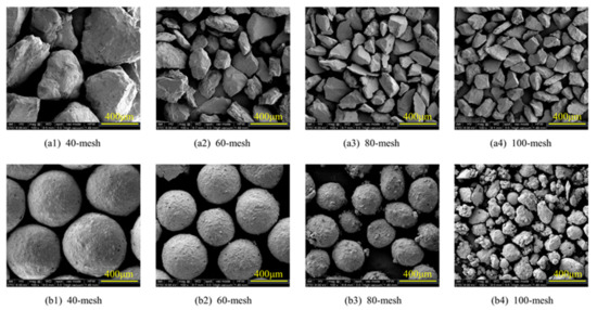
Figure 1.
Scanning electron microscopy (SEM) image of abrasive particles: (a1–a4) Angular abrasive particles; (b1–b4) Spherical abrasive particles.
The particle-size distribution of the abrasives was analyzed using a laser particle-size tester. As shown in Figure 2, the particle-size distributions of the two types of abrasives were close to a normal distribution, indicating good dimensional consistency. Table 2 lists the data from the particle-size distributions. The median particle size (D50) and average particle size (Dav) were relatively close, and they decreased with increasing mesh number. Therefore, the abrasive particles meet the specifications and satisfy the requirements of the experiments.
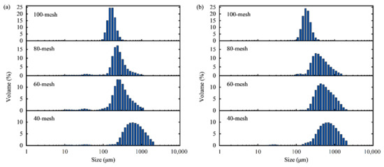
Figure 2.
Size distribution of the abrasive particles: (a) Angular abrasive particles; (b) Spherical abrasive particles.
Table 2.
Parameters of abrasive particle size distribution.
2.2. Experimental Equipment
Figure 3 shows a schematic of the wet blast cleaning equipment, which is an automatic wet shotting machine Model SW100100 from INTERNOR. The equipment consists of a gun, slurry pump, slurry tank, flow meter, pressure gauge, regulator, specimen holder, automatic feeding devices in X- and Y-directions, and manual adjustment devices in the Z-direction. The operation of the machine is controlled by PLC. During operations, the slurry (the mixture of abrasive particles and water) is pumped by the slurry pump and is delivered to the gun through the fluid delivery pipe. Compressed air enters the gun through the air delivery pipe. In the gun, the slurry is accelerated by compressed air and ejected through the nozzle into a jet. Then, the jet hits the surface of the specimens to achieve the desired cleaning.
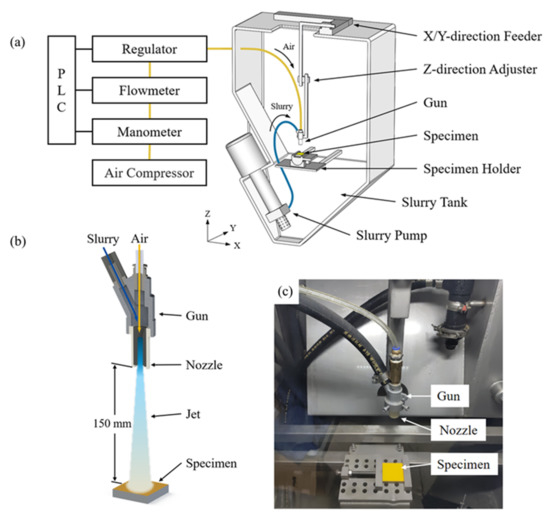
Figure 3.
Equipment of the cleaning experiment: (a) Structural diagram of the equipment; (b) Schematic of the cleaning process; (c) Actual image of the equipment.
Firstly, through the control experiment, the effect of abrasive particles shape was investigated. Specimens of 60-mesh angular and spherical abrasive particles were used for the cleaning experiments. Each specimen was passed 10 times by the gun, and the mass of the specimen after each pass was recorded, then the cleaning process was explored by analyzing the variation of mass with the number of passes. The experimental parameters are listed in Table 3. Specifically, the feed rate in the Y direction was 15 mm/s. Higher feed rates cause the specimen to be passed by the jet in less time, resulting in a smaller mass loss for each cleaning and providing more data for a better understanding of the cleaning process. After each cleaning, the specimens were rinsed with clean water, dried, and finally weighed using an electronic scale.
Table 3.
Parameters for the first experiment.
Secondly, to explore the effects of the shape and size of the abrasive particles on the removal mechanism, brown corundum and spherical abrasive particles of four sizes were used for the cleaning experiment, and the surface microtopographies of the specimens after cleaning were characterized and analyzed. The parameters for the experiment are listed in Table 3. The main aim of the experiment was to observe and analyze the surface microtopographies of the cleaned specimens; hence, each specimen was passed only once. Thus, the feed rate in the Y direction was 5 mm/s to ensure effective cleaning of the coatings to expose the substrates. The equipment was thoroughly cleaned every time the abrasive particles were replaced.
2.3. Characterization Methods
A laser particle-size tester (Winner 2008A, Jinan Winner Particle Instrument Stock Co., Ltd., Jinan, China) was used to examine the particle size and its distribution. For the test, water was used as the dispersion medium, the sonication time was 30 s, the analysis mode was free distribution, and the statistical method was volume distribution.
The thickness of the paint film was measured using an INSTRUMENT R&D TC100 coating thickness gauge with accuracy of ±(3% + 2 μm). The measurement was conducted at five random points, and the average of the five values was recorded.
The mass of the specimens was measured using a G&G JJ324BF electronic scale with accuracy of 10−4 g. Each specimen was weighed thrice, and the average value was recorded.
KEYENCE (HONGKONG) VK-X200K laser scanning confocal microscope (LSCM) was used to scan the surface of the cleaned specimen to obtain 3D microtopographies of the surface. A 10× standard objective was used.
Microscopic topography of the cleaned specimens was observed using a QUANTA FEG 250 scanning electron microscope (SEM) (FEI Company (Thermo Fisher Scientific), Waltham, MA, USA). The accelerating voltages used were 8 and 20 kV, and a secondary electron probe with a spot size of 3.0 was used. Several areas were randomly selected for observations.
3. Results and Discussion
3.1. Cleaning Process
The change in the mass of the specimens after cleaning with the two types of abrasive particles (60-mesh) is shown in Figure 4a,b, which show the change in the mass of the specimens as a function of the number of the passes by the gun, and Figure 4c shows the average removed mass of the specimens in each pass. When angular abrasive particles were used, the mass of both specimens gradually decreased with increasing number of passes (Figure 4a), and the average mass loss was relatively low (less than 0.01 g) and relatively constant as the number of passes increased (Figure 4c). However, as shown in Figure 4b, the mass of the specimens did not decrease steadily with an increase in the number of passes when spherical abrasive particles were used. According to the speed of mass change, the entire cleaning process could be divided into three stages: the initiation (I), development (D), and stabilization (S) stages. Considering both Figure 4b,c, in the I stage, the mass of the specimens decreased slowly, and the mass loss was lower than 0.01 g; in the D stage, the mass of the specimen decreased rapidly and significantly, and the maximum mass loss exceeded 0.04 g; in the S stage, the mass of the specimens decreased steadily, and the mass loss was approximately 0.01 g. Notably, for all passes, the mass loss of the specimens cleaned with spherical abrasive particles was higher than that of the specimens cleaned with angular abrasive particles.
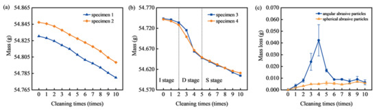
Figure 4.
Variation of specimen mass with the number of passes using (a) angular abrasive particles and (b) spherical abrasive particles. (c) Average mass loss of specimens per pass.
Such a significant difference in the cleaning processes indicated that the cleaning was influenced by the properties of the abrasive particles. Therefore, the surface microtopographies of the cleaned specimens were further characterized to investigate the removal mechanism.
3.2. Three-Dimensional Microtopographies of the Specimens after Cleaning
Based on the microtopographies and distribution of the paint, the specimen surface could be divided into three parts: the unaffected area, where the area was not impacted by the jet and the paint was not cleaned; the affected area, where the area was impacted by the periphery of the jet and the paint was damaged; and the cleaned area, where the area was impacted by the center of the jet and paint was completely removed, exposing the substrate. Figure 5 shows a schematic of the classified surface areas of the specimens.
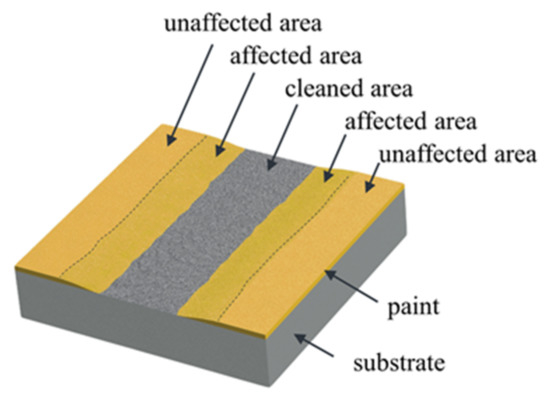
Figure 5.
Schematic of the classified surface areas of the specimen after cleaning.
Figure 6(a1,b1,c1,d1) show the specimens after cleaning with 40-mesh, 60-mesh, 80-mesh, and 100-mesh angular abrasive particles, respectively. The yellow part was the acrylic paint, and the silvery gray part was the substrate exposed after cleaning. The smaller the size of the abrasive particles, the smaller the area of the substrate exposed after cleaning, indicating that the cleaning ability decreased as the size of the abrasive particles decreased. The junction areas (A1-1, A2-1, A3-1, and A4-1) between the cleaned area and the affected area on the specimens was further characterized by LSCM, and the 3D microtopographies of four areas are shown in Figure 6(a2,b2,c2,d2), and the corresponding cross-sectional profiles are shown in Figure 6(a3,b3,c3,d3). In the four areas, the distributions of paint were similar, showing a “slope-like” trend, and the thickness of the paint gradually decreased to zero from the affected area to the cleaned area. The distribution indicates that the thickness of the paint was gradually decreased during the cleaning process, indicating that the paint was gradually removed, and not debonding of the entire paint layer. However, the surface microtopographies and thickness distribution of the paint in the cleaning area were different after cleaning with abrasive particles of different sizes. Therefore, we measured four characteristic values of these four areas: the maximum height of the area, average height of the area, surface roughness (Ra) of the paint, and slope of the paint in the section profile. The paint in the cleaning area in A1-1 was still thick, the maximum height of the area was 238.3630 μm, the average height was 105.0998 μm, and the Ra of the paint was 27.156 μm. In the cross-sectional profile, the gradient of the gently sloping paint was 5.15°. The paint in A2-1 and A3-1 showed similar surface microtopographies and thickness distributions, but their four characteristic values were lower than those in A1-1. The maximum heights of the two areas were 194.5265 and 209.0190 μm, and the average heights were 99.6084 and 99.3032 μm, respectively. The Ra of the paint in the areas was 16.446 and 16.063 μm, and the slopes of the paint were 3.27° and 2.74°, respectively. The characteristic values of A4-1 were the smallest, with maximum and average heights of 156.5995 and 82.1448 μm, respectively, The Ra of the paint was 15.560 μm, and the slope of the paint was 1.81°. Furthermore, as the particle size decreased, the characteristic values gradually decreased, indicating that the sloping paint was gradually flatter and the surfaces were gradually smoother. Therefore, the removed paint was gradually decreased and the paint was removed in smaller shapes.
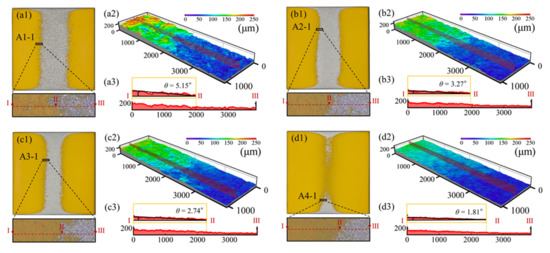
Figure 6.
Appearance of the specimens cleaned with angular abrasive particles of different sizes, 3D microtopographies, and cross-sectional profiles of the local area on the specimens. (a1–a3) 40-mesh; (b1–b3) 60-mesh; (c1–c3) 80-mesh; (d1–d3) 100-mesh.
The surfaces of the specimens after cleaning with spherical abrasive particles of different sizes are shown in Figure 7(a1,b1,c1,d1), the 3D microtopographies of the paint in the four areas (B1-1, B2-1, B3-1, and B4-1) are shown in Figure 7(a2,b2,c2,d2), and the corresponding cross-sectional profiles are shown in Figure 7(a3,b3,c3,d3). Compared with the specimens cleaned with angular abrasive particles, the exposed areas of the substrates also decreased as particle size decreased, but the exposed areas were larger, and the surface microtopographies and thickness distributions of the paint varied. The distributions of paint in the four areas also varied. Paint in B1-1 and B2-1 showed similar surface microtopographies and thickness distributions. The distributions of paint were “cliff-like”. The thickness of the paint was almost unchanged in the cleaning area and suddenly decreased to zero at the boundary between the cleaning and cleaned areas. The maximum heights of the two areas were 240.3675 and 253.5920 μm, and the average heights were 142.8896 and 139.4244 μm, respectively. The paint surfaces in the two areas were flat and smooth, and the Ra was only 7.384 and 4.898 μm, respectively. A “cliff-like” distribution was also observed in B3-1 after being cleaned with 80-mesh abrasive particles. However, the surface of the paint was no longer smooth but damaged, and Ra was 24.693 μm. Moreover, the thickness slightly decreased, with maximum and average heights of 232.5480 and 114.3987 μm, respectively. After cleaning with 100-mesh abrasive particles, the “cliff-like” distribution of the paint in B4-1 was no longer obvious, but there was still a small steep drop. The paint was very thin, the maximum and average heights were only 134.6775 and 80.0064 μm, respectively, and Ra decreased to 11.750 μm. Although the paint in the four areas showed a “cliff-like” distribution, B1-1 and B2-1 were the most significant, indicating that the paint cleaned with 40-mesh and 60-mesh abrasive particles seemed to be delaminated and rapidly removed, whereas the paint cleaned with 80-mesh and 100-mesh abrasive particles were not, but were removed gradually. Moreover, comparing the characteristic values, those of the specimens after cleaning with 40-mesh and 60-mesh abrasive particles were close, indicating that the removal forms of the paint seemed to be the same, whereas those of the paint cleaned with 80-mesh and 100-mesh abrasive particles were other forms. Furthermore, paint removal caused by delamination was quite significant, meaning that 40-mesh and 60-mesh abrasive particles had a stronger cleaning ability.
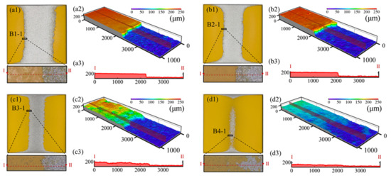
Figure 7.
Appearance of the specimens cleaned with spherical abrasive particles of different sizes, 3D microtopographies, and cross-sectional profiles of the local area on the specimens. (a1–a3) 40-mesh; (b1–b3) 60-mesh; (c1–c3) 80-mesh; (d1–d3) 100-mesh.
3.3. SEM Images of the Specimens after Cleaning
Figure 8(a1–a4) show the appearance and SEM images of the surfaces at A1-2 and A1-3 of the specimen after cleaning with 40-mesh angular abrasive particles. In Figure 8(a2), the red dotted line is the boundary between the paint and the substrate: the left side is the paint, and the right side is the substrate. The paint was thin and sloping, and the boundary was not obvious. In addition, the surface of the paint was damaged, and the damaged surface was smooth, indicating a brittle fracture. As shown in Figure 8(a3,a4) (after magnification), there were several microcutting grooves, plowing grooves, and cracks on the surface of the paint at A1-3. Figure 8(a4) shows obvious large cracks at the bottom of the plowing groove. These features are also shown in Figure 8(b2–b4,c2–c4,d2–d4), however, as the size of the abrasive particles decreased, these features became more and more microscopic and can only be presented upon further magnification (Figure 8(b4,c4,d4)), and the boundary between paint and substrate became progressively indistinguishable. Hence, the sloping distribution of the paint, the inconspicuous boundary, and the damage morphology of the paint indicated that the paint was removed in flakes and the removal amount in a single pass was small.
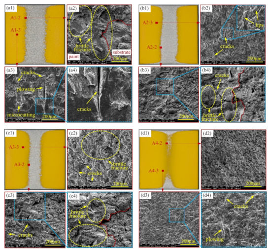
Figure 8.
SEM images of the local area of the specimens cleaned with angular abrasive particles of different sizes: (a1–a4) 40-mesh; (b1–b4) 60-mesh;(c1–c4) 80-mesh; (d1–d4) 100-mesh.
Figure 9(a1–a4) show the appearance and SEM images of the surfaces at B1-2 and B1-3 of the specimen after cleaning with 40-mesh spherical abrasive particles. In Figure 9(a2), there was a very obvious height difference between the paint (left) and the substrate (right) and an obvious boundary between the two. The edges of the paint were broken off nearly vertically. Furthermore, there were some longitudinal cracks perpendicular to the substrate surface that were deep and through the paint. As shown in Figure 9(a3,a4), there were some round impact craters in B1-3, the paint in the impact crater underwent plastic deformation, and there were some tiny cracks at the edges of the impact craters. Similar features were also present in other specimens as shown in Figure 9(b2–b4,c2–c4,d2–d4). However, there were differences in the surface morphology and thickness of the paint. In Figure 9(a2,b2), the paint was very thick without obvious thinning, and the surface was relatively flat and smooth. However, as shown in Figure 9(c2,d2), as the abrasive size decreased the thickness of the paint also gradually decreased and the surface of the paint was no longer flat and significantly damaged. Compared with the specimens after cleaning with angular abrasive particles, the paint in the affected area of the specimens after cleaning with spherical abrasive particles was “cliff-like” and the residual paint was thicker, indicating that the form of paint removal was chunkier when cleaning.
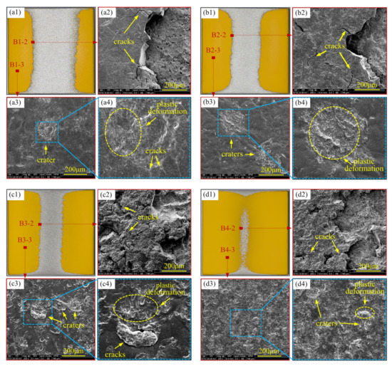
Figure 9.
SEM images of the local area of the specimens cleaned with spherical abrasive particles of different sizes: (a1–a4) 40-mesh; (b1–b4) 60-mesh; (c1–c4) 80-mesh; (d1–d4) 100-mesh.
3.4. Analysis of Removal Mechanism
Two types of abrasive particles with different particle sizes were used for the cleaning experiments. The cleaning process and the microtopographical features of the paint cleaned with different abrasive particles were different. These differences indicated that the removal mechanisms of the particles were different, which also varied with the shape and size of the abrasive particles.
3.4.1. Removal Mechanism of Angular Abrasive Particles
The angular abrasive particles could generate high stress when impacting the paint due to their sharp edges, resulting in cracks on the paint, which expanded into the paint as the impact proceeded. As shown in the microtopographies of the specimens after cleaning, the cracks gradually became transverse cracks parallel to the substrate surface in the process of downward expansion, and new transverse cracks sprouted. Arjula et al. reported that new transverse cracks are formed parallel to the substrate surface because the shear stress concentration at the crack tip is greater than the shear strength of the material [33]. The paint undergoes brittle fracture and breaks out as flakes due to the expansion and intersection of cracks. Thereafter, water jets can enter it and create a “water wedge”, which expands the cracks [34,35]. Herein, the numerous microcutting and plowing grooves on the paint indicate that the abrasive particles microcut and plowed the paint during the cleaning, resulting in the removal of the paint. The occurrence of microcutting and plowing shows that some of the abrasive particles had a certain horizontal velocity, indicating that their impact angles were below 90° [36]. Although the impact angle was set at 90° during the experiment, the abrasive particles did not all impact at 90° on the specimen. The abrasive particles bounce back after impact, and the bouncing particles may be hit by high-energy particles from the blasting gun, changing the direction of the two particles. Hence, a lot of impact angles should be expected. These microcutting and plowing phenomena occurred in the cleaning area, which was impacted by the periphery of the jet; thus, microcutting and plowing grooves were observed in this part.
Therefore, as shown in Figure 10, the main removal mechanism of angular abrasive particles includes brittle fracture caused by cracks resulting from large impact stress, microcutting and plowing, and the “water wedge” of the jet. The size of the abrasive particles did not significantly affect the cleaning mechanism. The paint cleaned with abrasive particles of different sizes showed similar microtopographies, only that the microtopographical features of the paint cleaned with the smaller abrasive particles were more microscopic.
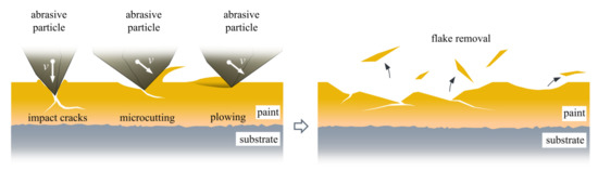
Figure 10.
Removal mechanism of angular abrasive particles.
3.4.2. Removal Mechanism of Spherical Abrasive Particles
For the spherical abrasive particles, the microtopographies of the specimens cleaned with 40-mesh and 60-mesh abrasive particles were similar but different from those of the specimens cleaned with 80-mesh and 100-mesh abrasive particles. When the specimens were cleaned with 40-mesh and 60-mesh abrasive particles, the contact area during impact was large because of the spherical shape; thus, the impact stress generated was small and could not peel off the paint immediately. This is the reason why the mass of the specimens did not decrease obviously in the I stage. As the cleaning proceeded, the paint was repeatedly impacted by the abrasive particles, and although the impact stress was not sufficient to reach the stress limit to destroy the paint, it could lead to fatigue. We speculate that these cracks were caused by fatigue. As shown in Figure 9, the paint in the affected areas of the specimens was all impacted by the abrasive particles, but the cracks appeared on the part near the cleaned area, not near the unaffected area. The paint in this part was closer to the center of the jet, and there were more abrasive particles in the center of the jet. Therefore, the paint here was more frequently impacted by the abrasive particles, which leads to fatigue and fatigue cracks. As shown in Figure 9(b1,b2), the paint peeled off clean. The surface of the exposed substrate was very clean and free of paint residue, indicating that the paint was detached from the substrate due to interfacial cracking. We speculate that the accumulated energy from repeated impacts was not completely released, which caused large tangential stress between the paint and the substrate, thus leading to interfacial cracks. As cleaning further progressed, longitudinal-through fatigue cracks interweaved with transverse interfacial cracks, resulting in block delamination removal of paint. The microtopographies of the specimens after cleaning with 80-mesh and 100-mesh spherical abrasive particles were more similar to those of the specimens cleaned with angular abrasive particles. Further, the paint was not delaminated but gradually removed when cleaning with 80-mesh and 100-mesh angular abrasive particles, similar to the form of paint removal when cleaning with angular abrasive particles. However, the paint was removed more, and its removal form was small blocks. There are two possible reasons for this: the small size of the abrasive particles had less kinetic energy, which was not enough to cause longitudinal-through cracks and interfacial cracks; the abrasive particles had lower sphericity, and the bud-like protrusions on the surface played the role of corners, making them similar to angular abrasive particles. For the specimens cleaned with spherical abrasive particles of all sizes, impact craters appeared on the surface of the paint, resulting in small amounts of paint peeling in the form of plastic removal.
Therefore, as shown in Figure 11, the main removal mechanisms of spherical abrasive particles are as follows. For large particles, they include brittle fracture caused by fatigue-generated cracks and interfacial cracks due to tangential stresses, small plastic deformation, and “water wedge” action. Small particles show a similar mechanism as spherical and angular particle composites (brittle fracture due to fatigue-generated cracks and impact cracks). In addition, plastic deformation and “water wedge” action occur.
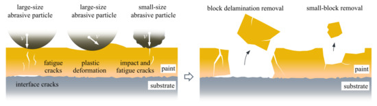
Figure 11.
Removal mechanism of spherical abrasive particles.
The cleaning process also further confirmed the difference in the removal mechanism. The microcutting and plowing of the angular abrasive particles did not take time to grow and intersect like cracks, resulting in the immediate removal of the paint. Thus, as shown in Figure 4a, the mass of the specimens started to decrease from the beginning of the experiment. Spherical abrasive particles mainly rely on fatigue cracks caused by repeated impacts to remove paint, which accumulates over time; therefore, as shown in Figure 4b, the mass of the specimens did not decrease significantly in the I stage. The paint was removed rapidly and substantially only when fatigue cracks developed in the D stage. On the other hand, the differences in the removal mechanism were also reflected in the cleaning ability of the abrasive particles. Considering Figure 4c, Figure 8 and Figure 9, the mass loss and exposed substrate area of the specimens after cleaning with spherical abrasive particles were larger, indicating that their cleaning ability was greater.
4. Conclusions
In this study, we investigated the effects of the shape and size of abrasive particles on the wet blast cleaning of paint. Four sizes of angular and spherical abrasive particles were investigated. The cleaning process was studied based on the change in the specimen mass, and the microtopographies of the cleaned paint were characterized by SEM and LSCM. Based on the results, the following conclusions are drawn:
- (1)
- The cleaning process varies with the abrasive particle type. The cleaning process of angular abrasive particles is constant, with an increasing number of passes, but that of spherical abrasive particles is divided into three stages: the initiation, development, and stabilization stages.
- (2)
- The main removal mechanism of angular abrasive particles includes brittle fracture due to the emergence and expansion of cracks caused by large impact stress, microcutting and plowing, and “water wedge”. Therefore, the paint is removed in flakes. The size of abrasive particles has a negligible effect on the removal mechanism.
- (3)
- The main removal mechanism of spherical abrasive particles varies with the particle size. For large abrasive particles, brittle fracture due to a combination of fatigue-generated cracks and interface cracks caused by tangential stresses is predominant. As a result, the paint is removed in block delaminations. However, for small abrasive particles, brittle fracture caused by fatigue cracks and impact cracks due to large impact stresses are predominant. Therefore, the paint is removed in small blocks. Furthermore, for all sizes of abrasive particles, plastic deformation and “water wedge” action contribute to the removal process.
- (4)
- The difference in the removal mechanism of the particles is reflected in the cleaning efficiency. Spherical abrasive particles have higher cleaning efficiency than angular abrasive particles. In addition, the larger the size of the abrasive particles, the greater the cleaning ability and the higher the cleaning efficiency.
This study serves as a good basis for investigating the process parameters of wet blast cleaning and would promote the development of remanufacturing cleaning. The surfaces of the specimens used in this study are flat, whereas those used in actual remanufacturing cleaning may have some depressions and protrusions. Therefore, the mechanism of the cleaning process on nonplanar surfaces should be further explored.
Author Contributions
Conceptualization, C.L.; data curation, S.W., X.W. and Y.R.; formal analysis, C.L.; funding acquisition, X.J.; investigation, C.L.; methodology, C.L.; project administration, X.J. and F.L.; supervision, X.J. and F.L.; validation, C.L.; visualization, S.W.; writing—original draft, C.L.; writing—review & editing, X.J., S.W. and X.W. All authors have read and agreed to the published version of the manuscript.
Funding
This work is supported by the National Natural Science Foundation of China (No. 51875324).
Institutional Review Board Statement
Not applicable.
Informed Consent Statement
Not applicable.
Data Availability Statement
Not applicable.
Conflicts of Interest
The authors declare no conflict of interest.
References
- Lee, C.-M.; Woo, W.-S.; Roh, Y.-H. Remanufacturing: Trends and issues. Int. J. Precis. Eng. Manuf.-Green Technol. 2017, 4, 113–125. [Google Scholar] [CrossRef]
- Lieder, M.; Rashid, A. Towards circular economy implementation: A comprehensive review in context of manufacturing industry. J. Clean. Prod. 2016, 115, 36–51. [Google Scholar] [CrossRef]
- Matsumoto, M.; Yang, S.; Martinsen, K.; Kainuma, Y. Trends and research challenges in remanufacturing. Int. J. Precis. Eng. Manuf.-Green Technol. 2016, 3, 129–142. [Google Scholar] [CrossRef]
- Liu, W.; Zhang, B.; Li, Y.; He, Y.; Zhang, H. An environmentally friendly approach for contaminants removal using supercritical CO2 for remanufacturing industry. Appl. Surf. Sci. 2014, 292, 142–148. [Google Scholar] [CrossRef]
- Peng, S.; Li, T.; Tang, Z.; Shi, J.; Zhang, H. Comparative life cycle assessment of remanufacturing cleaning technologies. J. Clean. Prod. 2016, 137, 475–489. [Google Scholar] [CrossRef]
- Li, M.-Z.; Liu, W.; Qing, X.-C.; Yu, Y.; Liu, L.-H.; Tang, Z.-J.; Wang, H.-J.; Dong, Y.-Z.; Zhang, H. Feasibility study of a new approach to removal of paint coatings in remanufacturing. J. Mater. Process. Technol. 2016, 234, 102–112. [Google Scholar] [CrossRef]
- Li, X.; Zhang, Q.; Zhou, X.; Zhu, D.; Liu, Q. The influence of nanosecond laser pulse energy density for paint removal. Optik 2018, 156, 841–846. [Google Scholar] [CrossRef]
- Madhukar, Y.K.; Mullick, S.; Nath, A.K. Development of a water-jet assisted laser paint removal process. Appl. Surf. Sci. 2013, 286, 192–205. [Google Scholar] [CrossRef]
- Long, Y.; Li, J.; Timmer, D.H.; Jones, R.E.; Gonzalez, M.A. Modeling and optimization of the molten salt cleaning process. J. Clean. Prod. 2014, 68, 243–251. [Google Scholar] [CrossRef]
- Yao, S. Carbon Cleaning Research and Process Optimization for Remanufactured Parts with Molten Salt. Master’s Thesis, Shandong University, Jinan, China, 2016. [Google Scholar]
- Nie, Y. Molten Salt Cleaning Process Research of Remanufacturing Engine Typical Fouling. Master’s Thesis, Shandong University, Jinan, China, 2015. [Google Scholar]
- Guo, Q. The Research and Application of High-pressure Waterjet Cleaning Based on Remanufacturing. Master’s Thesis, Shandong University, Jinan, China, 2015. [Google Scholar]
- Teimourian, H.; Shabgard, M.R.; Momber, A.W. De-painting with high-speed water jets: Paint removal process and substrate surface roughness. Prog. Org. Coat. 2010, 69, 455–462. [Google Scholar] [CrossRef]
- Kambham, K.; Sangameswaran, S.; Datar, S.R.; Kura, B. Copper slag: Optimization of productivity and consumption for cleaner production in dry abrasive blasting. J. Clean. Prod. 2007, 15, 465–473. [Google Scholar] [CrossRef]
- Chen, G.X.; Kwee, T.J.; Tan, K.P.; Choo, Y.S.; Hong, M.H. Laser cleaning of steel for paint removal. Appl. Phys. A 2010, 101, 249–253. [Google Scholar] [CrossRef]
- Wu, S.; Jia, X.; Xiong, S.; Li, F.; Ma, M.; Wang, X.; Li, C. Process Parameters Optimization of Wet Shot Peening for Paint Cleaning. Sustainability 2021, 13, 12915. [Google Scholar] [CrossRef]
- Xiong, S.; Jia, X.; Wu, S.; Li, F.; Ma, M.; Wang, X. Parameter Optimization and Effect Analysis of Low-Pressure Abrasive Water Jet (LPAWJ) for Paint Removal of Remanufacturing Cleaning. Sustainability 2021, 13, 2900. [Google Scholar] [CrossRef]
- Xiong, S. Technical Study on Paint Removal of Remanufacturing Parts by Wet Shot Peeving Cleaning. Master’s Thesis, Shandong University, Jinan, China, 2021. [Google Scholar]
- Papini, M.; Spelt, J.K. Organic coating removal by particle impact. Wear 1997, 213, 185–199. [Google Scholar] [CrossRef]
- Papini, M.; Spelt, J. The plowing erosion of organic coatings by spherical particles. Wear 1998, 222, 38–48. [Google Scholar] [CrossRef]
- Papini, M.; Spelt, J.K. Indentation-induced buckling of organic coatings part I. Int. J. Mech. Sci. 1998, 40, 1043–1059. [Google Scholar] [CrossRef]
- Papini, M.; Spelt, J.K. Indentation-induced buckling of organic coatings part II. Int. J. Mech. Sci. 1998, 40, 1061–1068. [Google Scholar] [CrossRef]
- Djurovic, B.; Jean, É.; Papini, M.; Tangestanian, P.; Spelt, J.K. Coating removal from fiber-composites and aluminum using starch media blasting. Wear 1999, 224, 22–37. [Google Scholar] [CrossRef]
- Zouari, B.; Touratier, M. Simulation of organic coating removal by particle impact. Wear 2002, 253, 488–497. [Google Scholar] [CrossRef]
- Dong, Y. Mechanism and Experiment Study of Paint layer cleaning based on Abrasive Water Jet Technology. Master’s Thesis, Dalian University of Technology, Dalian, China, 2015. [Google Scholar]
- Liu, Y.; Zou, C.; Zang, M.; Chen, S. Experimental study on mechanical property and stone-chip resistance of automotive coatings. Mater. Res. Express 2022, 9, 16402. [Google Scholar] [CrossRef]
- Oka, Y.I.; Okamura, K.; Yoshida, T. Practical estimation of erosion damage caused by solid particle impact. Wear 2005, 259, 95–101. [Google Scholar] [CrossRef]
- Naveed, M.; Schlag, H.; König, F.; Weiß, S. Influence of the Erodent Shape on the Erosion Behavior of Ductile and Brittle Materials. Tribol Lett 2017, 65, 18. [Google Scholar] [CrossRef]
- Ning, S.M.; Yu, Q.M.; Liu, T.J.; Zhang, K.; Zhang, H.L.; Wang, Y.; Li, Z.H. Influence of particle shape on erosion behavior of EB-PVD thermal barrier coatings. Ceram. Int. 2022, 48, 8627–8640. [Google Scholar] [CrossRef]
- Mohseni-Mofidi, S.; Drescher, E.; Kruggel-Emden, H.; Teschner, M.; Bierwisch, C. Particle-Based Numerical Simulation Study of Solid Particle Erosion of Ductile Materials Leading to an Erosion Model, Including the Particle Shape Effect. Materials 2021, 15, 286. [Google Scholar] [CrossRef] [PubMed]
- Abouel-Kasem, A. Particle Size Effects on Slurry Erosion of 5117 steels. J. Tribol. 2011, 133, 014502. [Google Scholar] [CrossRef]
- Nguyen, V.B.; Nguyen, Q.B.; Zhang, Y.W.; Lim, C.; Khoo, B.C. Effect of particle size on erosion characteristics. Wear 2016, 348–349, 126–137. [Google Scholar] [CrossRef]
- Arjula, S.; Harsha, A.P. Study of erosion efficiency of polymers and polymer composites. Polym. Test. 2006, 25, 188–196. [Google Scholar] [CrossRef]
- Dhanawade, A.; Kumar, S. Experimental study of delamination and kerf geometry of carbon epoxy composite machined by abrasive water jet. J. Compos. Mater. 2017, 51, 3373–3390. [Google Scholar] [CrossRef]
- Shanmugam, D.K.; Nguyen, T.; Wang, J. A study of delamination on graphite/epoxy composites in abrasive waterjet machining. Compos. Part A Appl. Sci. Manuf. 2008, 39, 923–929. [Google Scholar] [CrossRef]
- Alam, T.; Farhat, Z.N. Slurry erosion surface damage under normal impact for pipeline steels. Eng. Fail. Anal. 2018, 90, 116–128. [Google Scholar] [CrossRef]


Publisher’s Note: MDPI stays neutral with regard to jurisdictional claims in published maps and institutional affiliations. |
© 2022 by the authors. Licensee MDPI, Basel, Switzerland. This article is an open access article distributed under the terms and conditions of the Creative Commons Attribution (CC BY) license (https://creativecommons.org/licenses/by/4.0/).