Article

Outage Probability Analysis and Transmit Power Optimization for Blind-Reconfigurable Intelligent Surface-Assisted Non-Orthogonal Multiple Access Uplink

by
Vinoth Babu Kumaravelu
1,*,
Agbotiname Lucky Imoize
2,3,*,
Francisco R. Castillo Soria
4,
Periyakarupan Gurusamy Sivabalan Velmurugan
5,
Sundarrajan Jayaraman Thiruvengadam
5,
Arthi Murugadass
6 and
Vishnu Vardhan Gudla
7
1
Department of Communication Engineering, School of Electronics Engineering, Vellore Institute of Technology, Vellore 632014, India
2
Department of Electrical and Electronics Engineering, Faculty of Engineering, University of Lagos, Akoka, Lagos 100213, Nigeria
3
Department of Electrical Engineering and Information Technology, Institute of Digital Communication, Ruhr University, 44801 Bochum, Germany
4
Telecommunications Department, Faculty of Science, Autonomous University of San Luis Potosí (UASLP), San Luis Potosí 78300, Mexico
5
Department of Electronics and Communication Engineering, Thiagarajar College of Engineering, Madurai 625015, India
6
Department of Computer Science and Engineering (AI & ML), Sreenivasa Institute of Technology and Management Studies, Chittoor 517127, India
7
Department of Electronics and Communication Engineering, Aditya Engineering College, Surampalem 533437, India
*
Authors to whom correspondence should be addressed.
Sustainability 2022, 14(20), 13188; https://doi.org/10.3390/su142013188
Submission received: 19 August 2022 / Revised: 24 September 2022 / Accepted: 10 October 2022 / Published: 14 October 2022

Abstract

:
Fifth-generation (5G) advancements improve transmitter and receiver functionalities, but the propagation environment remains uncontrolled. By changing the phase of impinging waves, reconfigurable intelligent surfaces (RIS) have the potential to regulate radio propagation environments. RIS-assisted non-orthogonal multiple access (NOMA) improves spectrum efficiency while enabling massive connectivity. The uplink outage probability expressions for blind-RIS-NOMA are derived in this work using RIS as a smart reflector (SR) and RIS as an access point (AP). Extensive Monte-Carlo simulations are performed to validate the derived closed-form expressions. The optimal powers to be allocated to the users are also derived in order to maximize the uplink sum capacity. In comparison to the sub-optimal power allocation, the optimal power allocation enhances the sum capacity. In terms of sum capacity for 20 dB signal-to-noise ratio (SNR) and 32 reflecting elements, it is demonstrated that the blind-RIS-NOMA surpasses the conventional NOMA by 38%. The sum capacity and outage performances are enhanced by the addition of RIS elements.

1. Introduction

During the practical implementation of several of the core fifth-generation (5G) technologies, there are significant hurdles [1]. The network service providers in China, for example, recently announced the shutdown of a few 5G base stations (BS) mounted with massive multiple input multiple output (MIMO) [2]. The increased number of radio frequency (RF) chains necessitates higher hardware costs and higher energy consumption. To meet the growing traffic demands, cell size must be shrunken. This necessitates an increasing number of BSs or access points (AP). This raises the expense of maintenance while also causing practical concerns, such as interference and backhaul management. Exploiting higher frequency bands causes considerable propagation losses, necessitating more complicated signal processing.
Following the completion of the standardization and commercialization of 5G networks, wireless researchers have begun looking for new technologies to support sixth-generation (6G) networks. Since they reconfigure the environment with nearly passive, low-cost elements, reconfigurable intelligent surfaces (RIS) or intelligent reflecting surfaces (IRS) have been identified as viable components for next-generation networks. The RIS system uses abundant low-cost, passive reflecting elements mounted on a planar surface to regulate the amplitude and phase of incident signals [3,4]. Active RF chains are not required for RIS, and nearly passive reflecting elements are required. When compared to massive MIMO, the hardware cost and energy consumption are significantly lower. They do not cause noise amplification or self-interference in the way that full duplex transmission does. As a result, it is more appealing than half-duplex relays. RIS can be readily installed on walls, billboards, automobiles, lampposts, and so on. With the help of RIS, cell coverage and network throughput can be greatly boosted.
The number of wirelessly connected devices, as well as the range of wireless services available, such as the internet of everything (IoE), virtual reality (VR), augmented reality (AR), and so on, is rapidly increasing. As a result, next-generation multiple access strategies should be capable of serving a high number of users with additional resources, while maintaining a low level of complexity [5,6]. While permitting a certain degree of multiple access interference at the receivers, non-orthogonal multiple access (NOMA) boosts spectral efficiency and facilitates massive connectivity [7]. In NOMA, the signals pertaining to several users are superimposed in the power domain to more effectively utilize the spectrum. NOMA is classified into two types: fixed and ordered NOMA. In ordered NOMA, the decoding order is determined based on the channel gain of the users, as opposed to fixed NOMA, where the decoding order is predetermined. Because of its appealing qualities, RIS can be combined with other cutting-edge technologies such as NOMA, physical layer security, simultaneous wireless information and power transfer (SWIPT), cognitive radios, autonomous cars, and unmanned aerial vehicles (UAV)-assisted communication, etc. [8,9,10]. The integration of power-domain NOMA with RIS can increase its spectral efficiency and massive connectivity. The symbols used in this work are listed in Nomenclature.
The order in which the remaining manuscript is arranged is as follows: Section 2 lists the works connected to RIS and NOMA. The closed-form outage probability expressions for blind-RIS-smart reflector (SR)-NOMA uplink and blind-RIS-AP-NOMA uplink are derived in Section 3. The optimum powers to allocate for maximizing uplink sum capacity are detailed in Section 4. In Section 5, Monte-Carlo simulations are performed to verify the obtained analytical expressions. Section 6 wraps up the work by considering future works.

2. Related Work

In [11], the RIS-assisted millimetre wave (mmWave) multi-user system’s uplink is examined. By jointly optimizing RIS phase shifts, analog-to-digital converter (ADC) quantization bits, and a beamforming selection matrix under the hardware constraints, the attainable sum capacity is increased. A block coordinated descent (BCD)-based technique is suggested to solve this non-convex problem. It is shown that the proposed BCD algorithm works better than cutting-edge methods. To increase spectrum efficiency, a multi-user uplink with RIS support is recommended in [12]. In this work, a virtual constellation is built using RIS to transmit data from an additional user. By taking into account two users, the analytical average bit error rate (ABER) expressions are obtained.
For cost- and power-effective coverage extension, a hybrid transmission strategy combining RIS and decode-and-forward (DF) relays is recommended in [13]. Simulations demonstrate that when used in conjunction rather than as competing technologies, RIS and DF relaying significantly improve rate and error performance. An RIS-aided DF cooperative relaying with energy harvesting is presented in [14]. The effect of spatial correlation between RIS elements is also investigated. In terms of energy harvesting capability and outage probability, the proposed system is analyzed. Finally, index modulation (IM) is added to the idea of joint RIS and DF relaying. For indoor and outdoor environments and various frequency bands, the benefits of RIS deployment are examined in [15]. For both single- and multiple-RIS, the system is tested. It has been demonstrated that RIS-assisted systems greatly enhance achievable rates and error performance for indoor and outdoor environments, as well as different operating frequencies.
For orthogonal frequency division multiplexing (OFDM)-based NOMA, a low-complexity user selection and power allocation mechanism is presented in [16]. Users who do not meet the derived criterion are removed. The expressions for closed-form optimal power allocation are derived to maximize the weighted sum capacity of users. The results reveal that the suggested system outperforms the optimal exhaustive user search technique, while being significantly less complex. In [17], NOMA-aided mmWave networks are presented, which can suit the needs of users in a variety of applications. For user association, the Lagrange dual decomposition approach is employed, while power and subcarrier allocation are handled using semi-supervised learning and deep neural networks. The proposed method enhances energy efficiency while meeting the quality of service (QoS), power budget, and interference limitations constraints.
The uplink and downlink multiple user power domain NOMA is presented in [18], where it is assumed that the fading links of each user follow distinct distributions, such as Rayleigh, Rician, Nakagami- m , Nakagami- q , κ μ , and η μ . Closed-form outage probability expressions are developed for both uplink and downlink, assuming both statistical channel state information and instantaneous channel-based ordering. The simulation results are finally presented to verify the analytical expressions. NOMA can be utilized in land mobile satellite communications to improve coverage and link reliability [19]. Two terrestrial user nodes are used to execute the NOMA uplink, while a satellite is used to do successive interference cancellation (SIC) or joint decoding. The shadowed Rician fading channel is used to develop the closed-form outage probability expressions. Monte-Carlo simulations are performed to validate the closed-form expressions.
Downlink NOMA’s energy efficiency and fairness are maximized by optimizing subcarrier and power allocation jointly [20]. To accomplish this, a novel greedy subcarrier allocation approach with minimal complexity and fast convergence is proposed. NOMA and cognitive radio (CR) are powerful solutions that address wireless communication’s spectrum scarcity issue. NOMA and CR are integrated in [21] to improve spectrum efficiency. For a two-user case, the closed-form outage probability expressions are constructed. It is also proven that fairness between two users is realized through proper power factor allocation. NOMA does not surpass orthogonal multiple access (OMA) in terms of spectral efficiency gain when the channel gains of various users are not significantly different [22]. In these circumstances, classic OMA is preferable. In NOMA, fairness among users can be attained through effective power allocation. However, increasing the rate of weaker users may result in a decrease in the rate of stronger users. The addition of RIS to NOMA can improve its performance by enabling stronger combined channels.
The effects of coherent and random phase shifting on the performance of RIS-aided NOMA are investigated in [23]. Analytical and simulation results reveal the trade-off between complexity and reliability. To improve reception reliability, a low-complexity phase selection approach is also presented. In [24], multiple RIS are used in NOMA to increase the quality of each user’s received signal. Based on the availability of a line-of-sight (LoS) between the BS and the user, the outage probability expressions are derived. For high signal-to-noise-ratio (SNR) regimes, the upper and lower bounds of outage probability expressions are derived. It is proven that the diversity order is not degraded when using a discrete phase shifter. It is also proven that RIS with a three-bit discrete phase shifter achieves near-optimal outage performance. The simulation results further demonstrate that RIS outperforms full duplex DF relays.
In [25], the outage probability of RIS-assisted NOMA downlink transmission is examined for two users. RIS is used here between the source and the users. It has been shown that the introduction of RIS increases the performance of the far user. Analysis is also done on the impact that the number of RIS elements, power factor allocation, desired rates, and SNR have on the probability of an outage. Fairness among users is ensured by the implementation of RIS.
In [22], the joint optimization of transmit beamforming at the BS and phase shifts at the RIS are solved by block coordinated descent and semi-definite relaxation techniques to improve the user fairness in a downlink scenario of RIS-assisted NOMA system. Depending on the channel strength, the users are ordered. It is shown that the suggested RIS-assisted NOMA outperforms the traditional NOMA and traditional OMA with and without RIS in terms of the downlink sum capacity. It employs a low-resolution phase shifter with a performance that is nearly identical to that of an ideal RIS with an infinite resolution phase shifter. Here, the outage probability of ordered users is not investigated. It is noted that even for more passive controllable reflecting elements, the improvements in sum capacity are not appreciably greater. The authors intended to increase user fairness in this case. As a result, even with higher SNR, the sum capacity remains nearly constant. In this study, an LoS is assumed to exist between the BS and the RIS, and the BS-RIS channel is modeled using the Rician distribution. Rayleigh distribution is used to model the RIS-users channel since it is expected that there is a non-line-of-sight (NLoS) between the RIS and the users. The LoS assumption between BS and RIS is not realistic in many cases. The system has not been analyzed for RIS as an AP setup.
In [26], the performance of the cell edge user device is improved by employing IRS-assisted NOMA in both the uplink and the downlink. In this paper, a blind-RIS system is proposed for the uplink scenario of both users in a NOMA system. For each case, closed-form outage probability and Ergodic rate expressions are derived. The number of RIS elements appears to have an effect on the diversity order. Furthermore, the RIS-assisted system outperforms the full duplex DF relay system. In [27], it is proven that RIS-aided mmWave NOMA in the downlink scenario outperforms mmWave NOMA without RIS. A downlink IRS-aided system over fading channels is considered in which two users are served by different multiple access techniques, namely, NOMA, time division multiple access (TDMA) and frequency division multiple access (FDMA) system in [28]. A success convex approximation method is framed for the joint optimization of phase shift and resource allocation in solving average sum rate maximization. It is observed that the focus is mainly on the sum rate maximization and error performance of an RIS-assisted downlink NOMA system with and without the assistance of intelligent RIS.
RIS is an excellent option for improving the performance of vehicle-to-everything (V2X) applications. In [29], it is proven that RIS improves QoS demands for vehicle-to-infrastructure (V2I) and vehicle-to-vehicle (V2I) communications, assuming slowly varying channels. However, the nature of V2X channels is rapidly changing. Recently, the concept of blind-RIS was introduced in [30]. It has been proven that blind-RIS systems have the advantage of improving SNR by N times at the user end. In blind-RIS, low-cost and passive reflector elements are used for transmission without RF processing. This is more suitable for the uplink process. The following research gaps have been identified from the related work:
  • The majority of the research assumes intelligent RIS, where the BS-RIS and RIS-users’ channels are known in advance at the RIS. Each RIS element in these models is supposed to pre- and post-cancel the phase distortions brought on by the related channels. The channels are rapidly varying in applications such as V2X. It is quite difficult to gather precise channel information for every user, especially when there are many users and reflecting elements;
  • The majority of classic works presuppose the deployment of RIS between the transmitter and receiver. The received signal at the RIS may be quite weak when it is far from the transmitter. RIS may not therefore provide the anticipated benefits. The majority of studies examined the sum capacity and outage probability for RIS when configured as an SR. These models might not be realistic in all scenarios;
  • Further, it is also noted that outage analysis and optimal power allocation for near user and far user of the uplink NOMA system with RIS have not been addressed.
In this paper, the concept of blind-RIS is used for the uplink process, especially in the NOMA system. Motivated by these observations, the technical contributions of this paper are listed below:
  • Two different system models are proposed for the blind-RIS-assisted uplink NOMA system:
    • RIS is modeled as a smart reflector (SR) for the near and far users of the uplink NOMA system and it is termed as blind-RIS-SR-NOMA.
    • RIS is modeled as an access point (AP) for the near and far users of the uplink NOMA system and it is termed as blind-RIS-AP-NOMA.
  • The optimization problem is formulated to allocate optimal powers at both near and far users to maximize the sum rate of the proposed uplink NOMA systems. Closed-form expressions for optimal power allocation are also obtained by solving the optimization problem;
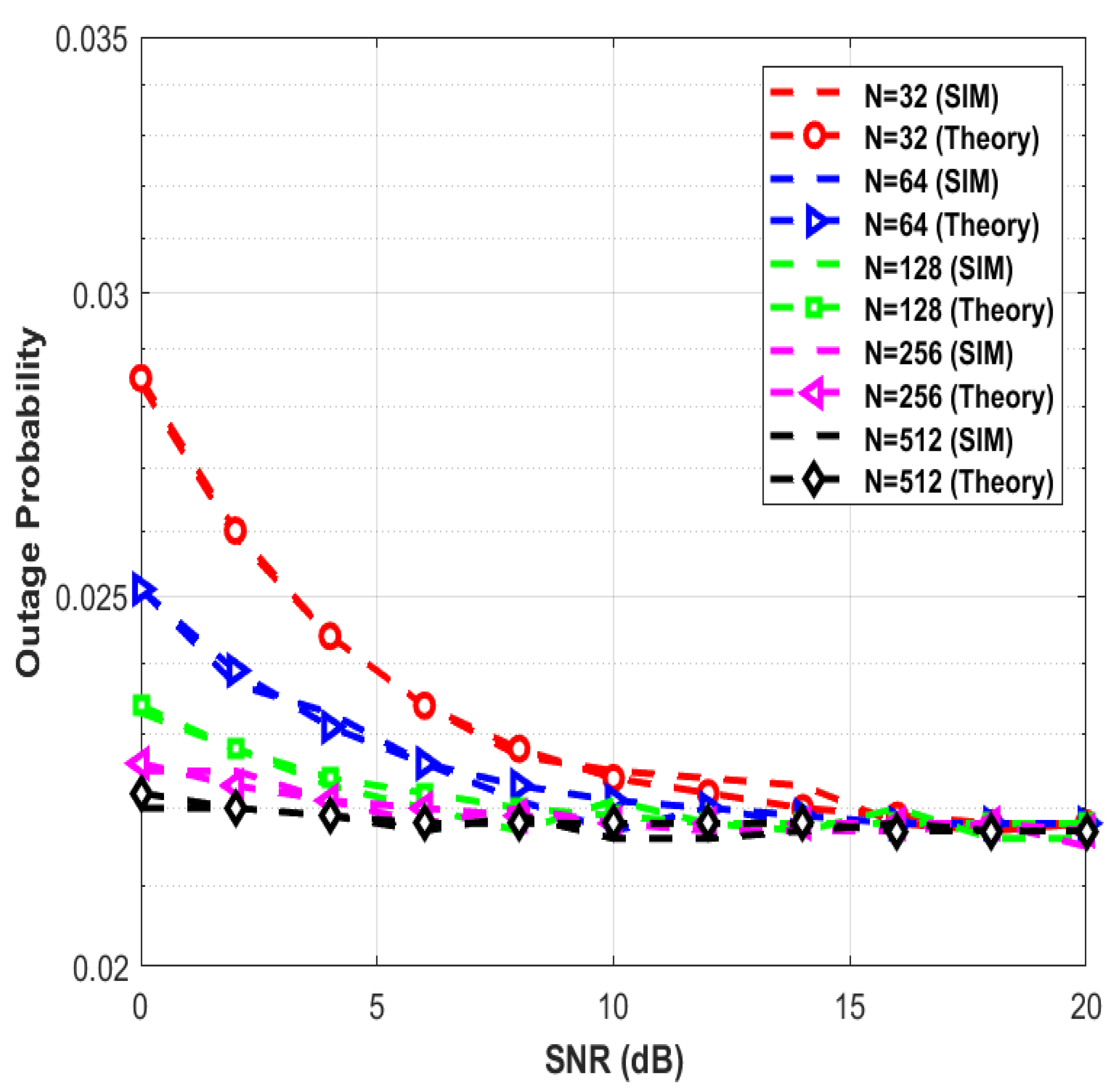
  • Extensive Monte-Carlo simulations are performed to corroborate the closed-form expressions that have been derived. The analytical and simulation curves are nearly identical, indicating that the obtained expressions are accurate.

3. Outage Analysis of Blind-RIS-NOMA Uplink System

In this section, uplink outage probability expressions are derived considering RIS as an SR and AP.

3.1. Outage Probability of the Blind-RIS-SR-NOMA System for Uplink Transmission
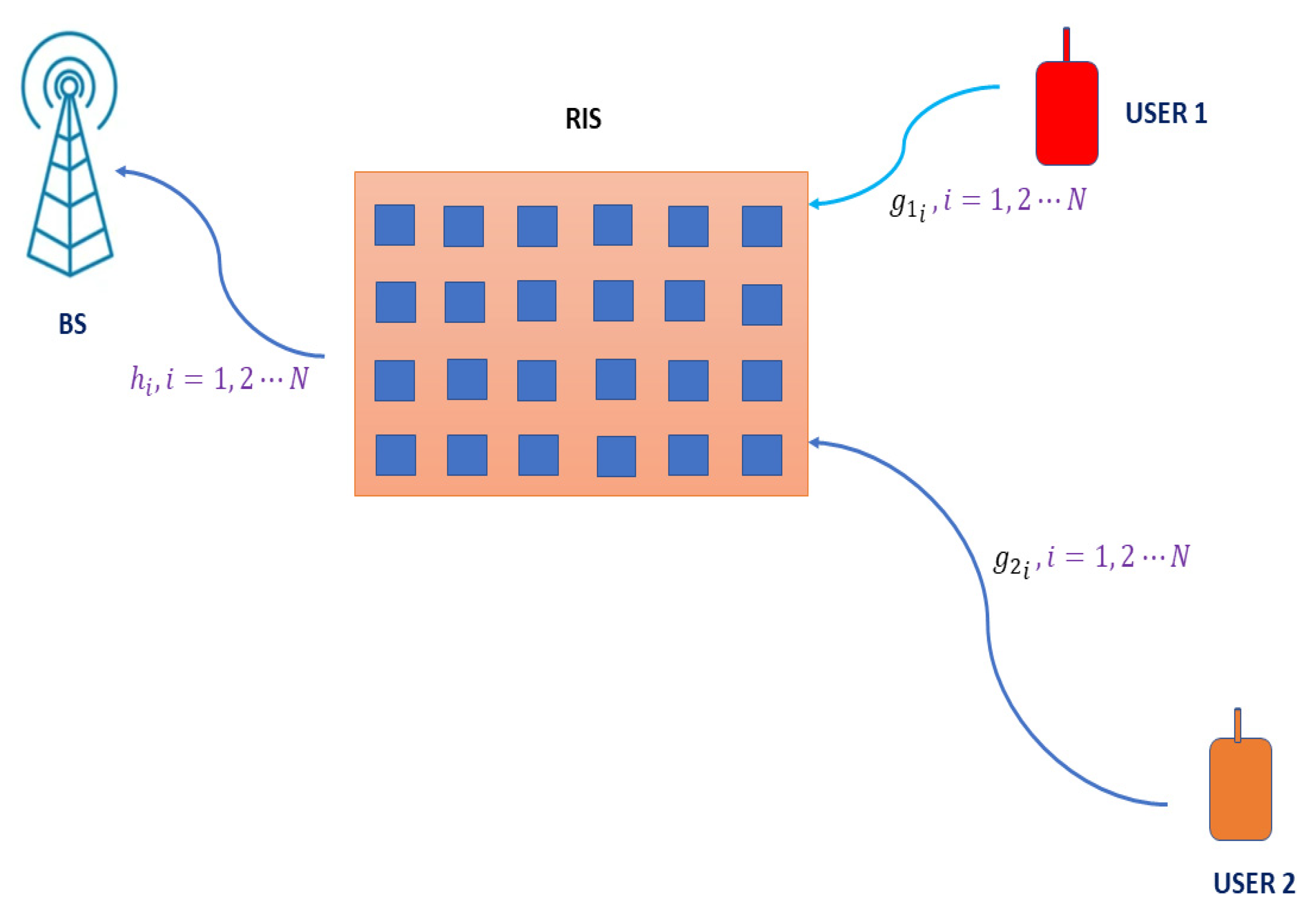
3.1.1. System Model

A sample scenario of a blind-RIS-SR-NOMA uplink system with two users is shown in Figure 1. Blind RIS, which does not perform any phase compensation, is deployed in the environment and serves as an SR. The BS is located far from the users. Due to this, users can communicate with the BS via two hops. Both users and the BS are equipped with single antenna. x 1 and x 2 are the unit average energy symbols corresponding to users 1 and 2, respectively. The channel between the jth user and the ith RIS element is represented as g j i . The channel is assumed to be zero mean circularly symmetric complex Gaussian with unit variance. The channel between the ith RIS element and BS is h i . μ 1   and μ 2   are the power fractions allotted to users 1 and 2, respectively, where μ 1   + μ 2   = 1 .
The signal from users received at the ith RIS element is given by
r i = g 1 i μ 1   κ s x 1 + g 2 i μ 2   κ s x 2 ,     i = 1 , 2 N
where κ s is the transmit power. The superposed signal received at the BS is [30,31,32]
y B S = i = 1 N h i r i + n B S
where n B S ( 0 , N 0 ) is the complex Gaussian noise added at the BS. Substituting (1) in (2) gives
y B S = ( i = 1 N h i g 1 i ) μ 1   κ s x 1 + ( i = 1 N h i g 2 i ) μ 2   κ s x 2 + n B S
Let
L = i = 1 N h i g 1 i ( 0 ,   N )
M = i = 1 N h i g 2 i ( 0 ,   N )
The BS decodes x 1 first, with x 2 being handled as interference. The SINR of user 1 at BS is given by [18]
υ x 1 = μ 1   κ s | L | 2 μ 2   κ s | M | 2 + N 0 = μ 1   κ | L | 2 μ 2   κ | M | 2 + 1  
where κ = κ s N 0 is the transmit SNR. Let α 1 = | L | 2 and α 2 = | M | 2 . The corresponding probability density functions (pdf) are given by
f A 1 ( α 1 ) = 1 N ν 1 2 e x p ( α 1 N ν 1 2 )
f A 2 ( α 2 ) = 1 N ν 2 2 e x p ( α 2 N ν 2 2 )
In the above expressions, N ν 1 2 and N ν 2 2 are the average channel gains of user 1 and user 2, respectively, i.e.,   E { α 1 } = N ν 1 2 and E { α 2 } = N ν 2 2 .

3.1.2. Outage Analysis for User 1

The outage for user 1 occurs under the condition
log 2 ( 1 + υ x 1 ) < D ˜ 1  
where D ˜ 1 is the desired rate of user 1. Substituting (6) in (9) and solving for α 1 gives the condition for the outage.
α 1 < D 1 ( 1 + μ 2 κ α 2 ) μ 1   κ
where D 1 = 2 D ˜ 1   1 . The detailed derivation of (10) is highlighted in Appendix A.
The probability of outage expression for user 1 is obtained using
P ( α 1 < D 1 ( 1 + μ 2 κ α 2 ) μ 1   κ ) = 0 F A 1 ( D 1 ( 1 + μ 2 κ α 2 ) μ 1   κ ) f A 2 ( α 2 ) d α 2
where the cumulative distributive function (CDF) of A 1 is expressed as
F A 1 ( D 1 ( 1 + μ 2 κ α 2 ) μ 1   κ ) = 0 D 1 ( 1 + μ 2 κ α 2 ) μ 1   κ f A 1 ( α 1 )   d α 1 = 1 e x p { D 1 ( 1 + μ 2 κ α 2 ) μ 1   κ N ν 1 2 }
The detailed derivation of (12) is highlighted in Appendix B. The above expression is a function of a random variable α 2 . This expression needs to be averaged with respect to α 2 . Substituting (12) in (11) gives
P ( α 1 < D 1 ( 1 + μ 2 κ α 2 ) μ 1   κ ) = 0 ( 1 e x p { D 1 ( 1 + μ 2 κ α 2 ) μ 1   κ N ν 1 2 } ) f A 2 ( α 2 ) d α 2
Solving the above expression results in a probability of outage of user 1, which is given by
P o u t U s e r 1 = 1 e x p { D 1 μ 1   κ N ν 1 2 } 1 + μ 2 D 1 ν 2 2 μ 1   ν 1 2
The detailed derivation of (14) is highlighted in Appendix C.

3.1.3. Outage Analysis for User 2

After decoding the signal of user 1, its impact is removed from the received superposed signal.
y 2 = ( i = 1 N h i g 2 i ) μ 2   κ x 2 + n B S
The SNR of user 2 is given by [18]
υ x 2 = μ 2   κ S | M | 2 N 0 = μ 2   κ | M | 2
The outage does not occur for user 2, when x 1 and x 2 are decoded successfully. The system should satisfy the following QoS requirements of both users [18].
log 2 ( 1 + υ x 1 ) D ˜ 1  
log 2 ( 1 + υ x 2 ) D ˜ 2  
where D ˜ 2 is the desired rate demand of user 2. The following conditions for no outage of user 2 are obtained by simplifying (17) and (18).
α 1 D 1 ( 1 + μ 2 κ α 2 ) μ 1   κ  
α 2 D 2 μ 2   κ
where D 2 = 2 D ˜ 2   1 . The expression in (19) can be obtained by using steps similar to Appendix A. The detailed derivation of (20) is highlighted in Appendix D.
The probability of no outage is obtained using
P ( α 1 D 1 ( 1 + μ 2 κ α 2 ) μ 1   κ , α 2 D 2 μ 2   κ ) = e x p ( ( D 1 μ 1   κ N ν 1 2 + D 2 μ 2   κ N ν 2 2 + D 1 D 2 μ 1   κ N ν 1 2 ) ) 1 + μ 2 D 1 ν 2 2 μ 1   ν 1 2
The detailed derivation of (21) is highlighted in Appendix E. The probability of outage of user 2 is given by
P o u t U s e r 2 = 1 e x p ( ( D 1 μ 1   κ N ν 1 2 + D 2 μ 2   κ N ν 2 2 + D 1 D 2 μ 1   κ N ν 1 2 ) ) 1 + μ 2 D 1 ν 2 2 μ 1   ν 1 2

3.2. Outage Probability of Blind-RIS-AP-NOMA System for Uplink Transmission

RIS is typically placed near the BS or receiver in real applications. In [30,31], RIS as an AP scenario is discussed in which the RIS is deployed quite close to the BS, and both are connected via a dedicated link. As a result, the BS-RIS channel is insignificant. The transmission is possible without RF processing. Figure 2 illustrates a typical blind-RIS-AP-NOMA uplink scenario. The signals received by each RIS element are combined at AP/BS. The superposed signal received at the BS is given by [32]
y B S = ( i = 1 N g 1 i ) μ 1   κ s x 1 + ( i = 1 N g 2 i ) μ 2   κ s x 2 + n B S
Let
L = i = 1 N g 1 i ( 0 ,   N )
M = i = 1 N g 2 i ( 0 ,   N )
We can obtain expressions like (14) and (22) for outages of user 1 and user 2, if we perform the analysis stated previously.

4. Optimal Power Allocation for Uplink Sum Capacity Maximization

The uplink sum capacity is given by
C = C U s e r 1 + C U s e r 2 = log 2 ( 1 + μ 1   κ   α 1 μ 2   κ   α 2 + 1 ) + log 2 ( 1 + μ 2   κ   α 2 )
where C U s e r 1 and C U s e r 2 are the capacity (b/s/Hz) achieved by user 1 and user 2, respectively.
C = log 2 ( μ 2   κ   α 2 + 1 + μ 1   κ   α 1 μ 2   κ   α 2 + 1 ) + log 2 ( 1 + μ 2   κ   α 2 )
Simplifying (27) results in
C = log 2 ( 1 + μ 2   κ   α 2 + μ 1   κ   α 1 )
Substituting μ 2 = 1 μ 1 in (28) gives
C = log 2 ( 1 + κ α 2 + μ 1 κ ( α 1 α 2 ) )
To maximize the sum capacity, the power fractions allocated to users 1 and 2 must be optimized. The users should be able to meet the expected QoS requirements without experiencing an outage, and the sum of the power fractions should equal 1. The following optimization problem is formulated in order to identify the feasible region for both users:
max μ 1 , μ 2   { log 2 ( 1 + κ α 2 + μ 1 κ ( α 1 α 2 ) ) }
Subject to
log 2 ( 1 + υ x 1 ) D ˜ 1   log 2 ( 1 + υ x 2 ) D ˜ 2   μ 1   + μ 2   = 1 0 < μ j < 1 ,   j = 1 , 2
From (29), it is clear that C is a monotonically increasing function of μ 1 . When μ 1 = 0 , C becomes 1 + κ α 2 . For μ 1 = 1 , C reaches 1 + κ α 1 . For maximum uplink capacity, μ 1 = 1 . This may not satisfy the QoS demand of user 2. The optimization problem formulated in (30) for optimal power allocation to user 1 and user 2 is non-convex in nature. Alternatively, an analytical method is used to identify the feasibility region. Solving (17) for μ 1 , the feasible region for user 1 can be obtained.
μ 1 D 1 ( 1 + κ α 2 ) κ ( α 1 + α 2 D 1 )
The detailed derivation of (31) is highlighted in Appendix F. Similarly, solving (20) for μ 1 gives a feasible region for user 2.
μ 1 κ α 2 D 2 κ   α 2
The detailed derivation of (32) is highlighted in Appendix G. By combining the conditions (31) and (32),
D 1 ( 1 + κ α 2 ) κ ( α 1 + α 2 D 1 ) μ 1 m i n μ 1 κ α 2 D 2 κ   α 2 μ 1 m a x
The above equation can be written as
D 1 ( 1 + κ α 2 ) κ ( α 1 + α 2 D 1 ) κ α 2 D 2 κ   α 2
Simplifying (34) for κ results in
κ D 1 α 1 + D 2 α 2 + D 1 D 2 α 1
The simplification of (34) is given in Appendix H. The condition in (35) is the minimum SNR required to meet the QoS constraints of both the users. The optimal power to be allocated for user 1 is the maximum value of μ 1 .
μ 1 o p t = κ α 2 D 2 κ   α 2
The remaining power is allocated to user 2
μ 2 o p t = 1 μ 1 o p t

5. Results and Discussion

In this section, Monte-Carlo simulations are used to substantiate the outage probability and sum capacity performances of the proposed blind-RIS-NOMA uplink. The simulations are repeated for 10 6 channel realizations and the average results are presented. The simulation parameters are listed in Table 1.
For the blind-RIS-assisted NOMA uplink, the closed-form probability of outage expressions is developed in this work. The related works have emphasized that NOMA does not necessarily outperform OMA. RIS is introduced to enhance the performance of conventional NOMA. Most classic works take an ideal RIS with an infinite resolution phase shifter into consideration. A low-resolution phase shifter RIS is taken into consideration in several works. Here, we sought to demonstrate that even a blind-RIS will have a considerable impact on the effectiveness of uplink outages and sum capacity. For a classic NOMA uplink, the probability of outage expressions is derived in [18].
The probability of outage expressions for user 1 of the traditional NOMA system is given by [18]
P o u t _ N O M A U s e r   1 = 1 e x p { D 1 μ 1   κ ζ 1 2 } 1 + μ 2 D 1 ζ 2 2 μ 1   ζ 1 2
where ζ 1 2 and ζ 2 2 are the average channel gains of user 1 and user 2 of a traditional NOMA system. The probability of outage expression for user 2 of a traditional NOMA system is given by [18]
P o u t _ N O M A U s e r   2 = 1 e x p ( ( D 1 μ 1   κ ζ 1 2 + D 2 μ 2   κ ζ 2 2 + D 1 D 2 μ 1   κ ζ 1 2 ) ) 1 + μ 2 D 1 ζ 2 2 μ 1   ζ 1 2
Hence, the proposed model is compared to the classic NOMA discussed in [18].
The outage performance of the proposed blind-RIS-SR-NOMA and traditional NOMA is shown in Figure 3. The power fractions assigned to users 1 and 2 are 0.9 and 0.1, respectively. The number of RIS elements is 32. Due to higher channel gain and more power allocation for user 1, the outage probability of user 1 of traditional NOMA is better than user 2. As per (38), a larger μ 1   makes larger e x p { D 1 μ 1   κ ζ 1 2 } . This results in a lower outage probability compared to user 2. The introduction of blind-RIS elements in the environment increases the array gain, thereby decreasing the outage probability. RIS adds N channel paths to create stronger combined channels. In accordance with (14) and (21), N is introduced to the probability of outage expressions for the RIS-assisted NOMA system. Higher μ 1   and N make e x p { D 1 μ 1   κ N ν 1 2 } in (14) higher. As a result, user 1 of the proposed system is less likely to experience an outage than in the conventional NOMA system. Similarly, N is introduced into the denominator of e x p ( 1 N ( D 1 μ 1   κ ν 1 2 + D 2 μ 2   κ ν 2 2 + D 1 D 2 μ 1   κ ν 1 2 ) ) of (21). When compared to a traditional NOMA system, a higher N introduces a significant reduction in the outage probability of user 2. At the SNR of 10 dB, user 1′s outage probability in the blind-RIS-SR-NOMA and traditional NOMA is 0.0224 and 0.0432, respectively. User 2’s outage probability in the blind-RIS-SR-NOMA and traditional NOMA is 0.0532 and 0.6558, respectively, for 10 dB SNR. A drastic reduction in outage probability is observed for user 2 when blind-RIS elements are introduced.
The outage analysis is repeated in Figure 4 by keeping everything the same as in Figure 3 except the power factors. Users 1 and 2 have been given power fractions of 0.7 and 0.3, respectively. User 1’s outage probability in the blind-RIS-SR-NOMA and traditional NOMA is 0.0798 and 0.1049, respectively, for 10 dB SNR. User 2’s outage probability in the blind-RIS-SR-NOMA and traditional NOMA is 0.0901 and 0.3767, respectively, for 10 dB SNR. It has been noted that the possibility of an outage for both systems has increased as a result of the reduction in power allocated to user 1. The probability of an outage for both systems is decreased by the increased power factor allocation for user 2.
For various choices of   N , the outage probability of user 1 in the blind-RIS-SR-NOMA uplink is shown in Figure 5. User 1 of blind-RIS-SR-NOMA has a lower outage probability than user 2 due to the higher channel gain and greater power allocation. The probability of an outage decreases as the number of reflecting elements grows. The outage probabilities of the proposed blind-RIS system are 0.0219, 0.0221, 0.0224, 0.0231, and 0.0244, with the number of elements 512, 256, 128, 64, and 32 at 4 dB SNR. At low SNR, it is observed that there is a gap between the theoretical and simulation curves, due to the assumptions made in (4) and (5) for mathematical tractability. However, the theoretical and simulation curves are nearly identical for higher values of N . For various choices of N , the outage probability of user 2 of the blind-RIS-SR-NOMA uplink is shown in Figure 6. The probability of an outage falls as the number of reflecting elements grows. The outage probability of a blind-RIS system is 0.0297, 0.0375, 0.053, 0.0833, and 0.1409 with N = 512 ,   256 ,   128 ,   64 ,   and   32 , at 4 dB SNR. For higher values of N , the analytical and simulation curves are found to be very similar.
According to the configuration of the simulation, user 1 has a stronger channel than user 2. The capacity of user 2 is reduced as a result of improper random power allocation. The sum capacity is finally reduced as a result. In the proposed work, the power factors are optimally chosen with the objective of maximizing the sum capacity while also satisfying the minimum rate requirements of each individual user. For various values of N , the sum capacity (b/s/Hz) of the blind-RIS-SR-NOMA uplink is shown in Figure 7. It has been observed that increasing N increases the sum capacity regardless of optimal or sub-optimal power allocations. To validate the performance of optimal power allocation, the following sub-optimal power allocation is used for comparison:
μ 1 s u b o p t = μ 1 m i n + μ 1 m a x 2
μ 2 s u b o p t = 1 μ 1 s u b o p t
The sum capacity is maximized when optimal powers are allocated as per (36) and (37), compared to sub-optimal power allocations as per (40) and (41). The sum capacity of the optimal and sub-optimal power allocations for N = 32 and 20 dB SNR are 13.21 b/s/Hz and 12.71 b/s/Hz, respectively. Other values of N show nearly identical gains.
In Figure 8, the outage performance of the proposed blind-RIS-AP-NOMA and traditional NOMA is shown. The parameters used in this simulation are similar to those in Figure 3. User 1 of the blind-RIS-AP-NOMA has a lower outage probability than user 2 due to the higher channel gain and greater power allocation. The presence of RIS elements in the environment boosts array gain, lowering the probability of an outage. Blind-RIS-AP-NOMA achieves nearly identical results as blind-RIS-SR-NOMA when compared to the traditional NOMA system. For various choices of N , the outage probability of user 1 of the blind-RIS-AP-NOMA uplink is compared in Figure 9. Figure 9’s explanation is identical to that of Figure 5. In Figure 10, the outage probability of user 2 of the blind-RIS-AP-NOMA uplink is shown for various values of N .
The proposed blind-RIS-AP-NOMA uplink’s sum capacity (b/s/Hz) is shown in Figure 11, for various values of N . It has been observed that raising N increases the sum capacity regardless of whether power allocations are optimal or sub-optimal. When optimal powers are allocated, as per (36) and (37), against sub-optimal power allocations, as per (40) and (41), the sum capacity is increased. For N   = 32 and 20 dB SNR, the sum capacities of the optimal and sub-optimal power allocations are 13.11 b/s/Hz and 12.64 b/s/Hz, respectively. Other N values yield essentially equal results.
For optimal and sub-optimal power allocations, the sum capacities (b/s/Hz) of NOMA, blind-RIS-SR-NOMA, and blind-RIS-AP-NOMA are compared in Figure 12. For all systems, the sum capacity of the optimal power allocation is greater than that of the sub-optimal power allocation. The blind-RIS-AP-NOMA system’s capacity is nearly identical to that of the blind-RIS-SR-NOMA system. For 32 RIS elements and 20 dB SNR, the sum capacity of the optimal power assigned blind-RIS-SR-NOMA, blind-RIS-AP-NOMA, and traditional NOMA is 13.21 b/s/Hz, 13.11 b/s/Hz, and 8.13 b/s/Hz, respectively. In comparison to the traditional NOMA system, this represents a 38% increase in sum capacity. The sum capacity of the optimal and sub-optimal power assigned blind-RIS-SR-NOMA is 14.12 b/s/Hz and 13.64 b/s/Hz, respectively, for 64 RIS elements and 20 dB SNR. The sum capacity for the optimal power allocation is 3.4% higher than for the sub-optimal power allocation. The sum capacity of optimal power allotted blind-RIS-SR-NOMA is improved by 6.44% by increasing N from 32 to 64. The number of reflecting elements can be increased to further improve the results.

6. Conclusions

Blind-RIS-SR-NOMA and blind-RIS-AP-NOMA uplink users’ outage probability expressions are derived in this paper. Monte-Carlo simulation curves are utilized to substantiate the derived closed-form expressions. The analytical and simulation curves are nearly identical, indicating that the obtained expressions are accurate. The probability of an outage decreases as the number of reflecting elements grows. The optimal powers to be allocated to the users are also determined to maximize the uplink sum capacity. Optimal power allocation has a higher sum capacity than sub-optimal power allocation. By increasing the number of reflecting elements, the sum capacity can be increased even further. The sum capacity of blind-RIS-SR-NOMA is likewise slightly higher than that of blind-RIS-AP-NOMA. In terms of sum capacity for 20 dB SNR and 32 RIS elements, the blind-RIS-SR-NOMA system surpasses the conventional NOMA system by 38%. This study can be expanded to include intelligent RIS-assisted communication, in which the channel information is known in advance at the RIS. This work can be practiced for discrete phase shifter-assisted RIS and generalized to a large number of users.

Author Contributions

The manuscript was written through the contributions of all authors. V.B.K. was responsible for the conceptualization of the topic; article gathering and sorting were carried out by V.B.K., A.L.I., F.R.C.S., P.G.S.V., S.J.T., A.M. and V.V.G.; manuscript writing and original drafting and formal analysis were carried out by V.B.K., A.L.I., F.R.C.S., P.G.S.V., S.J.T., A.M. and V.V.G.; writing of reviews and editing were carried out by V.B.K., A.L.I., F.R.C.S., P.G.S.V., S.J.T., A.M. and V.V.G.; V.B.K. led the overall research activity. All authors have read and agreed to the published version of the manuscript.

Funding

The work of Agbotiname Lucky Imoize was supported in part by the Nigerian Petroleum Technology Development Fund (PTDF) and in part by the German Academic Exchange Service (DAAD) through the Nigerian–German Postgraduate Program under grant 57473408.

Institutional Review Board Statement

Not applicable.

Informed Consent Statement

Not applicable.

Data Availability Statement

The data that support the findings of this paper are available from the corresponding author upon reasonable request.

Acknowledgments

The authors thank the anonymous reviewers for their valuable comments which help to improve the quality of this work.

Conflicts of Interest

The authors declare no conflict of interest related to this work.

Nomenclature

SymbolDescription
x j Unit average energy symbol corresponding to jth user
h i Channel between ith RIS element and BS
g j i   Channel between jth user and ith RIS element
μ j   Power fractions allotted to jth user
N Number of reflecting elements
κ s Transmit power
r i Signal from users received at the ith RIS element
y B S Superposed signal received at the BS
n B S Complex Gaussian noise added at the BS
L Combined channel effect of user 1 to BS
M Combined channel effect of user 2 to BS
α j Instantaneous channel gain of jth user
υ x 1 SINR of user 1 at BS
κ Transmit SNR
D ˜ j Desired rate of jth user
P o u t U s e r   j Probability of outage of jth user of proposed system
υ x 2 SNR of user 2
μ j o p t Optimal power allocated to jth user
μ j s u b o p t Sub-optimal power allocated to jth user
P o u t _ N O M A U s e r   j Probability of outage of jth user of NOMA system
ζ j 2 Average channel gain of jth user of traditional NOMA

Appendix A. Condition for an Outage at User 1

Substituting (6) in (9) gives
log 2 ( 1 + μ 1   κ α 1 μ 2   κ α 2 + 1 ) < D ˜ 1  
Taking antilog with respect to base-2 on both sides results in
1 + μ 1   κ α 1 μ 2   κ α 2 + 1 < 2 D ˜ 1  
μ 1   κ α 1 μ 2   κ α 2 + 1 < 2 D ˜ 1 1   D 1  
μ 1   κ α 1 < D 1 ( μ 2   κ α 2 + 1 )
Simplifying (A4) results in (10).

Appendix B. CDF of A 1

Substituting (7) in (12) gives
0 D 1 ( 1 + μ 2 κ α 2 ) μ 1   κ f A 1 ( α 1 )   d α 1 = 0 D 1 ( 1 + μ 2 κ α 2 ) μ 1   κ 1 N ν 1 2 e x p ( α 1 N ν 1 2 )   d α 1 = 1 N ν 1 2 0 D 1 ( 1 + μ 2 κ α 2 ) μ 1   κ e x p ( α 1 N ν 1 2 )   d α 1
Simplifying (A5) gives the expression in (12).

Appendix C. The Outage Probability Expression of User 1

Substituting (8) in (13) gives
P ( α 1 < D 1 ( 1 + μ 2 κ α 2 ) μ 1   κ ) = 0 ( 1 e x p { D 1 ( 1 + μ 2 κ α 2 ) μ 1   κ N ν 1 2 } ) 1 N ν 2 2 e x p ( α 2 N ν 2 2 )   d α 2
= 1 N ν 2 2 0 e x p ( α 2 N ν 2 2 )   d α 2 1 N ν 2 2 0 e x p { D 1 ( 1 + μ 2 κ α 2 ) μ 1   κ N ν 1 2 } · e x p ( α 2 N ν 2 2 )   d α 2
= 1 1 N ν 2 2 0   e x p { D 1 μ 1   κ N ν 1 2 } · e x p { D 1 μ 2 κ α 2 μ 1   κ N ν 1 2 } · e x p ( α 2 N ν 2 2 )   d α 2
= 1 1 N ν 2 2   e x p { D 1 μ 1   κ N ν 1 2 } 0 e x p { α 2 ( 1 N ν 2 2 + D 1 μ 2 κ μ 1   κ N ν 1 2 ) }   d α 2
= 1 1 N ν 2 2   e x p { D 1 μ 1   κ N ν 1 2 } e x p { α 2 ( 1 N ν 2 2 + D 1 μ 2 μ 1   N ν 1 2 ) } ( 1 N ν 2 2 + D 1 μ 2 μ 1   N ν 1 2 ) | 0
= 1 + 1 N ν 2 2   e x p { D 1 μ 1   κ N ν 1 2 } ( 0 1 ) ( 1 N ν 2 2 + D 1 μ 2 μ 1   N ν 1 2 )
This results in expression (14).

Appendix D. Condition for No Outage at User 2

Substituting (16) in (18) gives
log 2 ( 1 + μ 2   κ α 2 ) D ˜ 2  
Taking antilog with respect to base-2 on both sides results in
( 1 + μ 2   κ α 2 ) 2 D ˜ 2
μ 2   κ α 2 2 D ˜ 2 1 D 2
This results in expression (20).

Appendix E. Probability of No Outage at User 2

P ( α 1 D 1 ( 1 + μ 2 κ α 2 ) μ 1   κ , α 2 D 2 μ 2   κ ) = D 2 μ 2   κ F ¯ A 1 ( D 1 ( 1 + μ 2 κ α 2 ) μ 1   κ ) f A 2 ( α 2 ) d α 2
F ¯ A 1 ( D 1 ( 1 + μ 2 κ α 2 ) μ 1   κ ) = P ( α 1 D 1 ( 1 + μ 2 κ α 2 ) μ 1   κ ) = D 1 ( 1 + μ 2 κ α 2 ) μ 1   κ f A 1 ( α 1 ) d α 1
Substituting (7) in (A16) gives
F ¯ A 1 ( D 1 ( 1 + μ 2 κ α 2 ) μ 1   κ ) = 1 N ν 1 2 D 1 ( 1 + μ 2 κ α 2 ) μ 1   κ e x p ( α 1 N ν 1 2 ) d α 1
Simplifying (A17) results in
F ¯ A 1 ( D 1 ( 1 + μ 2 κ α 2 ) μ 1   κ ) = e x p { D 1 ( 1 + μ 2 κ α 2 ) μ 1   κ N ν 1 2 }
Substituting (A18) in (A15)
P ( α 1 D 1 ( 1 + μ 2 κ α 2 ) μ 1   κ , α 2 D 2 μ 2   κ ) = D 2 μ 2   κ e x p { D 1 ( 1 + μ 2 κ α 2 ) μ 1   κ N ν 1 2 } f A 2 ( α 2 ) d α 2
Substituting (8) in (A19)
P ( α 1 D 1 ( 1 + μ 2 κ α 2 ) μ 1   κ , α 2 D 2 μ 2   κ ) = D 2 μ 2   κ e x p { D 1 μ 1   κ N ν 1 2 } · e x p { D 1 μ 2 κ α 2 μ 1   κ N ν 1 2 } · 1 N ν 2 2 e x p ( α 2 N ν 2 2 )   d α 2
= 1 N ν 2 2   e x p { D 1 μ 1   κ N ν 1 2 } D 2 μ 2   κ e x p { D 1 μ 2 κ α 2 μ 1   κ N ν 1 2 } ·   e x p ( α 2 N ν 2 2 )   d α 2
= 1 N ν 2 2   e x p { D 1 μ 1   κ N ν 1 2 } D 2 μ 2   κ e x p { α 2 ( D 1 μ 2 μ 1   N ν 1 2 + 1 N ν 2 2 ) }   d α 2
= 1 N ν 2 2   e x p { D 1 μ 1   κ N ν 1 2 } ( D 1 μ 2 μ 1   N ν 1 2 + 1 N ν 2 2 ) [ 0 e x p { D 2 μ 2   κ ( D 1 μ 2 μ 1   N ν 1 2 + 1 N ν 2 2 ) } ]
= 1 N ν 2 2   e x p { D 1 μ 1   κ N ν 1 2 } ( D 1 μ 2 μ 1   N ν 1 2 + 1 N ν 2 2 ) ·   e x p { D 1 μ 2 D 2 μ 1 κ N ν 1 2 μ 2   } · e x p { D 2 μ 2   κ N ν 2 2 }
Simplifying and rearranging (A24) results in (21).

Appendix F. Lower Bound of Optimal μ1

Substituting (6) in (17) gives
log 2 ( 1 + μ 1   κ α 1 μ 2   κ α 2 + 1 ) D ˜ 1  
Taking antilog with respect to base-2 on both sides results in
1 + μ 1   κ α 1 μ 2   κ α 2 + 1 2 D ˜ 1
μ 1   κ α 1 μ 2   κ α 2 + 1 2 D ˜ 1 1 D 1  
μ 1   κ α 1 D 1 μ 2   κ α 2 + D 1
μ 1   κ α 1 D 1 ( 1 μ 1   ) κ α 2 + D 1
μ 1   κ α 1 D 1 + D 1 κ α 2 D 1 μ 1   κ α 2
μ 1 ( κ α 1 + D 1 κ α 2 ) D 1 ( 1 + κ α 2 )
Simplifying (A31) results in (31).

Appendix G. Upper Bound of Optimal μ1

From (A14)
( 1 μ 1 ) κ α 2 D 2
κ α 2 κ α 2 μ 1 D 2
κ α 2 μ 1 D 2 κ α 2
κ α 2 μ 1 D 2 + κ α 2
Simplifying (A35) results in (32).

Appendix H. Identifying the Feasibility Region

Rearranging (34) results in
D 1 α 2 ( 1 + κ α 2 ) ( κ α 2 D 2 )   ( α 1 + α 2 D 1 )
D 1 α 2 + D 1 κ α 2 2   κ α 1 α 2 + D 1 κ α 2 2 D 2 α 1 D 1 D 2 α 2
D 1 α 2 + D 2 α 1 + D 1 D 2 α 2   κ α 1 α 2
Simplifying (A38) results in (35).

References

  1. Liu, R.; Wu, Q.; Renzo, M.D.; Yuan, Y. A path to smart radio environments: An industrial viewpoint on reconfigurable intelligent surfaces. Wirel. Commun. 2022, 29, 202–208. [Google Scholar] [CrossRef]
  2. Available online: https://www.insidetelecom.com/hibernating-5g-stations-in-china-to-save-energy/ (accessed on 20 May 2022).
  3. Renzo, D.M.; Zappone, A.; Debbah, M.; Alouini, M.-S.; Chau, Y.; de Rosny, J.; Tretyakov, S. Smart radio environments empowered by reconfigurable intelligent surfaces: How it works, state of research, and the road ahead. IEEE J. Sel. Areas Commun. 2020, 38, 2450–2525. [Google Scholar] [CrossRef]
  4. Wu, Q.; Zhang, R. Intelligent reflecting surface enhanced wireless network via joint active and passive beamforming. IEEE Trans. Wirel. Commun. 2019, 18, 5394–5409. [Google Scholar] [CrossRef] [Green Version]
  5. Liu, Y.; Zhang, S.; Mu, X.; Ding, Z.; Schober, R.; Al-Dhahir, N.; Hossain, E.; Shen, X. Evolution of NOMA toward next generation multiple access (NGMA) for 6G. IEEE J. Sel. Areas Commun. 2022, 40, 1037–1071. [Google Scholar] [CrossRef]
  6. Yuan, Y.; Wang, S.; Wu, Y.; Poor, H.V.; Ding, Z.; You, X.; Hanzo, L. NOMA for next-generation massive IoT: Performance potential and technology directions. IEEE Commun. Mag. 2021, 59, 115–121. [Google Scholar] [CrossRef]
  7. Aldababsa, M.; Toka, M.; Gökçeli, S.; Kurt, G.K.; Kucur, O. A tutorial on nonorthogonal multiple access for 5G and beyond. Wirel. Commun. Mob. Comput. 2018, 2018, 9713450. [Google Scholar] [CrossRef] [Green Version]
  8. Li, S.; Duo, B.; Yuan, X.; Liang, Y.C.; Renzo, D.M. Reconfigurable intelligent surface assisted UAV communication: Joint trajectory design and passive beamforming. IEEE Wirel. Commun. Lett. 2020, 9, 716–720. [Google Scholar] [CrossRef] [Green Version]
  9. Tan, X.; Zhi, S.; Jornet, J.M.; Pados, D. Increasing indoor spectrum sharing capacity using smart reflect-array. In Proceedings of the 2016 IEEE International Conference on Communications (ICC), Kuala Lumpur, Malaysia, 22–27 May 2016; pp. 1–6. [Google Scholar]
  10. Liu, Y.; Qin, Z.; Elkashlan, M.; Gao, Y.; Hanzo, L. Enhancing the physical layer security of non-orthogonal multiple access in large-scale networks. IEEE Trans. Wirel. Commun. 2017, 16, 1656–1672. [Google Scholar] [CrossRef]
  11. Xiu, Y.; Zhao, J.; Basar, E.; Renzo, M.D.; Sun, W.; Gui, G.; Wei, N. Uplink achievable rate maximization for reconfigurable intelligent surface aided millimeter wave systems with resolution-adaptive ADCs. IEEE Wirel. Commun. Lett. 2021, 10, 1608–1612. [Google Scholar] [CrossRef]
  12. Yang, L.; Meng, F.; Hasna, M.O.; Basar, E. A novel RIS-assisted modulation scheme. IEEE Wirel. Commun. Lett. 2021, 10, 1359–1363. [Google Scholar] [CrossRef]
  13. Yildirim, I.; Kilinc, F.; Basar, E.; Alexandropoulos, G.C. Hybrid RIS-empowered reflection and decode-and-forward relaying for coverage extension. IEEE Commun. Lett. 2021, 25, 1692–1696. [Google Scholar]
  14. Jalaja, R.R.U.; Thirumavalavan, V.C.; Velmurugan, P.G.S.; Thiruvengadam, S.J.; Thiruvengadam, S.J. Spatially correlated dual hop ris aided next generation wireless systems: An outage perspective. IEEE Access 2021, 9, 56127–56139. [Google Scholar] [CrossRef]
  15. Yildirim, I.; Uyrus, A.; Basar, E. Modeling and analysis of reconfigurable intelligent surfaces for indoor and outdoor applications in future wireless networks. IEEE Trans. Commun. 2020, 69, 1290–1301. [Google Scholar] [CrossRef]
  16. Nain, G.; Das, S.S.; Chatterjee, A. Low complexity user selection with optimal power allocation in downlink NOMA. IEEE Wirel. Commun. Lett. 2017, 7, 158–161. [Google Scholar] [CrossRef]
  17. Zhang, H.; Zhang, H.; Long, K.; Karagiannidis, G.K. Deep learning based radio resource management in NOMA networks: User association, subchannel and power allocation. IEEE Trans. Netw. Sci. Eng. 2020, 7, 2406–2415. [Google Scholar] [CrossRef]
  18. Agarwal, A.; Chaurasiya, R.; Rai, S.; Jagannatham, A.K. Outage probability analysis for NOMA downlink and uplink communication systems with generalized fading channels. IEEE Access 2020, 8, 220461–220481. [Google Scholar] [CrossRef]
  19. Tegos, S.A.; Diamantoulakis, P.D.; Xia, J.; Fan, L.; Karagiannidis, G.K. Outage performance of uplink NOMA in land mobile satellite communications. IEEE Wirel. Commun. Lett. 2020, 9, 1710–1714. [Google Scholar] [CrossRef]
  20. Muhammed, A.J.; Ma, M.; Li, L.; Panagiotis, D.D.; Karagiannidis, G.K. Energy Efficient Power and Subcarrier Allocation for Downlink Non-Orthogonal Multiple Access Systems. In Proceedings of the 2019 IEEE 90th Vehicular Technology Conference (VTC2019-Fall), Honolulu, HI, USA, 22–25 September 2019; pp. 1–5. [Google Scholar]
  21. Nguyen, H.-N.; Le, C.-B.; Nguyen, T.N.; Do, D.-T. Study on outage performance gap of two destinations on CR-NOMA network. Telkomnika 2020, 18, 191–198. [Google Scholar] [CrossRef]
  22. Yang, G.; Xu, X.; Liang, Y.-C.; Renzo, M.D. Reconfigurable intelligent surface-assisted non-orthogonal multiple access. IEEE Trans. Wirel. Commun. 2021, 20, 3137–3151. [Google Scholar] [CrossRef]
  23. Ding, Z.; Schober, R.; Poor, H.V. On the impact of phase shifting designs on IRS-NOMA. IEEE Wirel. Commun. Lett. 2020, 9, 1596–1600. [Google Scholar] [CrossRef]
  24. Cheng, Y.; Li, K.H.; Liu, Y.; Teh, K.C.; Karagiannidis, G.K. Non-orthogonal multiple access (NOMA) with multiple intelligent reflecting surfaces. IEEE Trans. Wirel. Commun. 2021, 20, 7184–7195. [Google Scholar] [CrossRef]
  25. Do, D.-T.; Le, C.-B. Exploiting performance gap among two users in reconfigurable intelligent surfaces-aided wireless systems. Telkomnika 2022, 20, 1–8. [Google Scholar] [CrossRef]
  26. Cheng, Y.; Li, K.H.; Liu, Y.; The, K.C.; Poor, H.V. Downlink and uplink intelligent reflecting surface aided networks: NOMA and OMA. IEEE Trans. Wirel. Commun. 2021, 20, 3988–4000. [Google Scholar] [CrossRef]
  27. Xiu, Y.; Zhao, J.; Sun, W.; Renzo, M.D.; Gui, G.; Zhang, Z.; Wei, N. Reconfigurable intelligent surfaces aided mmWave NOMA: Joint power allocation, phase shifts, and hybrid beamforming optimization. IEEE Trans. Wirel. Commun. 2021, 20, 8393–8409. [Google Scholar] [CrossRef]
  28. Guo, Y.; Qin, Z.; Liu, Y.; Al-Dhahir, N. Intelligent reflecting surface aided multiple access over fading channels. IEEE Trans. Commun. 2020, 69, 2015–2027. [Google Scholar] [CrossRef]
  29. Chen, Y.; Wang, Y.; Zhang, J.; Renzo, M.D. QoS-driven spectrum sharing for reconfigurable intelligent surfaces (RISs) aided vehicular networks. IEEE Trans. Wirel. Commun. 2021, 20, 5969–5985. [Google Scholar] [CrossRef]
  30. Basar, E. Transmission through large intelligent surfaces: A new frontier in wireless communications. In Proceedings of the 2019 European Conference on Networks and Communications (EuCNC), Valencia, Spain, 18–21 June 2019; pp. 112–117. [Google Scholar]
  31. Basar, E.; Renzo, M.D.; de Rosny, J.; Debbah, M.; Alouini, M.-S.; Zhang, R. Wireless communications through reconfigurable intelligent surfaces. IEEE Access 2019, 7, 116753–116773. [Google Scholar] [CrossRef]
  32. Thirumavalavan, V.C.; Thiruvengadam, S.J. BER analysis of reconfigurable intelligent surface assisted downlink power domain NOMA system. In Proceedings of the 2020 International Conference on COMmunication Systems & NETworkS (COMSNETS), Bengaluru, India, 7–11 January 2020; pp. 519–522. [Google Scholar]
Figure 1. A sample scenario of the blind-RIS-SR-NOMA uplink.
Sustainability 14 13188 g001
Figure 2. A sample scenario of the blind-RIS-AP-NOMA uplink.
Sustainability 14 13188 g002
Figure 3. Outage probability comparison between blind-RIS-SR-NOMA and NOMA for μ 1 = 0.9 and μ 2 = 0.1 .
Sustainability 14 13188 g003
Figure 4. Outage probability comparison between blind-RIS-SR-NOMA and NOMA for μ 1 = 0.7 and μ 2 = 0.3 .
Sustainability 14 13188 g004
Figure 5. Outage probability comparison of blind-RIS-SR-NOMA user 1 for various choices of N .
Sustainability 14 13188 g005
Figure 6. Outage probability comparison of blind-RIS-SR-NOMA user 2 for various choices of N .
Sustainability 14 13188 g006
Figure 7. Sum capacity (b/s/Hz) comparison of blind-RIS-SR-NOMA for optimal and sub-optimal power allocations and various choices of N .
Sustainability 14 13188 g007
Figure 8. Outage probability comparison between blind-RIS-AP-NOMA and NOMA.
Sustainability 14 13188 g008
Figure 9. Outage probability comparison of blind-RIS-AP-NOMA user 1 for various choices of N .
Sustainability 14 13188 g009
Figure 10. Outage probability comparison of blind-RIS-AP-NOMA user 2 for various choices of N .
Sustainability 14 13188 g010
Figure 11. Sum capacity (b/s/Hz) comparison of blind-RIS-AP-NOMA for optimal and sub-optimal power allocations and various choices of N .
Sustainability 14 13188 g011
Figure 12. Sum capacity (b/s/Hz) comparison of NOMA, blind-RIS-SR-NOMA and blind-RIS-AP-NOMA for optimal and sub-optimal power allocations.
Sustainability 14 13188 g012
Table 1. Simulation parameters [18,21,25,30,31].
ParametersValue
Number of reflecting elements32, 64, 128, 256, 512
Number of users2
Average channel gain of user 15
Average channel gain of user 21
The desired rate of users (b/s/Hz)1
Power allocated to user 10.9, 0.7
Power allocated to user 20.1, 0.3
Block size106
Publisher’s Note: MDPI stays neutral with regard to jurisdictional claims in published maps and institutional affiliations.

