Article

Biofuel Technologies and Petroleum Industry: Synergy of Sustainable Development for the Eastern Siberian Arctic

by
Kirill A. Bashmur
1,
Oleg A. Kolenchukov
1,
Vladimir V. Bukhtoyarov
1,2,
Vadim S. Tynchenko
1,2,3,*,
Sergei O. Kurashkin
2,3,4,*,
Elena V. Tsygankova
5,
Vladislav V. Kukartsev
2,6,7 and
Roman B. Sergienko
8
1
Department of Technological Machines and Equipment of Oil and Gas Complex, School of Petroleum and Natural Gas Engineering, Siberian Federal University, 660041 Krasnoyarsk, Russia
2
Digital Material Science: New Materials and Technologies, Bauman Moscow State Technical University, 105005 Moscow, Russia
3
Information-Control Systems Department, Institute of Computer Science and Telecommunications, Reshetnev Siberian State University of Science and Technology, 660037 Krasnoyarsk, Russia
4
Laboratory of Biofuel Compositions, Siberian Federal University, 660041 Krasnoyarsk, Russia
5
Department of Foreign Languages for Natural Science, Siberian Federal University, 660041 Krasnoyarsk, Russia
6
Department of Informatics, Institute of Space and Information Technologies, Siberian Federal University, 660041 Krasnoyarsk, Russia
7
Department of Information Economic Systems, Institute of Engineering and Economics, Reshetnev Siberian State University of Science and Technology, 660037 Krasnoyarsk, Russia
8
Machine Learning Department, Gini Gmbh, 80339 Munich, Germany
*
Authors to whom correspondence should be addressed.
Sustainability 2022, 14(20), 13083; https://doi.org/10.3390/su142013083
Submission received: 22 August 2022 / Revised: 26 September 2022 / Accepted: 29 September 2022 / Published: 12 October 2022
(This article belongs to the Special Issue Biomass Resources for Biofuel Production)

Abstract

:
This article is a compilation of interdisciplinary studies aimed at ensuring the environmental, political, and economic sustainability of oil and gas-producing countries with a focus on areas with many years of permafrost. One of the main concepts adopted in this research was the desire to show that confronting various energy lobbies is not mandatory and that it is necessary to find compromises by finding and introducing innovative technologies for integrated development for the benefit of society, industry, and the state. This is particularly relevant due to the increasing share of hard-to-recover hydrocarbon reserves, widely represented in the fields of the Eastern Siberian Arctic, and because Russia is the leader in flare emissions. We thus present the relevance of using these gases as industrial waste while reducing the carbon footprint. The technology of biofuel production based on the use of supercritical liquid extraction in a well extractor is presented as a result of the development of the presented experimental devices representing the investigation of the processes of extraction in wells and reactors for the distillation of hydrocarbons from heavy oil components. The obtained yield of the desired product (hydrogen) of the thermocatalytic pyrolysis of the test extract was in the range of 44 to 118 L/h, depending on the catalyst. This information can help inform the direction of future ecological engineering activities in the Eastern Siberian Arctic region.

1. Introduction

Significant changes in global energy markets have recently been reflected as the growing need for energy, to develop and improve the efficiency of technology, to toughen environmental standards, etc. [1]. This shows that energy security and well-being are increasingly complex and multifaceted. These issues are increasingly included in the priorities discussed by leaders of all countries, at the level of congresses, forums, symposia, and other meetings in business circles, as well as in scientific communities.
The concept of the Energy Trilemma developed by the World Energy Council focuses on three main vectors of development of the fuel and energy complex: energy security, energy availability, and environmental sustainability. Economics, politics, and environmental protection are the three competing objectives of the energy trilemma [2,3] and their balance is the subject of years of contention from different perspectives. With the United Nations Sustainable Development Goals and the Paris Climate Agreement already being implemented in the world [4], the need for energy to contribute to the stable development of the world community should be clear and significant. Energy generation is now determined not only by economic indicators of feasibility but also by the growing social and environmental factors of society, corresponding to several side-by-side sustainable development paradigms presented by the UNO. The link between goal 7, “Achieving universal access to affordable, reliable, sustainable and modern energy for all”, and goal 13, “Taking urgent action to combat climate change and its consequences”, supported by the Paris Agreement international climate change treaty, is clear.
At the same time, there are justifiably more stringent requirements for ensuring energy security for facilities and farms that operate in territories in difficult conditions, in conditions of extreme climates, and in infrastructure isolation [5,6]. The creation of comfortable conditions for the functioning of human society and quality of life is coupled with a number of difficulties. The survival of mankind as a whole depends significantly on how much we can learn to live in a new way, that is, to protect nature and resources as much as possible, to introduce and use environmental and knowledge-intensive technologies, and to generate income with limited physical and energy resources.
The importance of addressing interrelated issues in this direction occurs due to the problem of a reliable energy supply in the developing northern and Arctic territories. Strategic guidelines for sustainable energy development are interesting and are identified and traced in the strategies of the countries of the Arctic region group: Russia, Canada, the USA, and Scandinavian countries [7,8,9]. This largely explains the particular importance of energy security, as expressed in the declaration of international organizations and regional associations, as well as in national energy strategies and laws. Energy systems located in remote areas can face many specific challenges, such as transport logistics problems, including limited fuel and spare parts supply during the year and the dependence of these supplies on weather conditions, and the lack of qualified field maintenance personnel [10,11].
We conclude that it is necessary to jointly study environmental and economic opportunities for the development of the energy complex, including renewable energy source (RES) technologies, which is consistent with the position of the authors of the study [12]. It is also necessary to do this individually for each case or region, as development decisions should be made on the basis of the reasonable use of natural capital, reduction in emissions, conservation of biological diversity, as well as the payback and efficiency of the project.
For example, due to the fact that the northern and Arctic zones of Eastern Siberia are climatically severe, underdeveloped, and poorly populated territories with large explored and exploited oil and gas reserves (33 hydrocarbon deposits of the Krasnoyarsk Territory) [13], the problems of the fuel and energy complex here are extreme. In the cold season, the rivers and the Northern Sea Route freeze, and only aviation and winter roads (routes along frozen rivers) are the modern transport routes to the north of Eastern Siberia. Fuel imported to the fields and purchased by oil and gas companies is necessary for the operation of numerous technological units, machines, and equipment, as well as for their own needs (heating and electricity generation). Thus, a significant carbon footprint is generated in these fields. At the same time, an even greater carbon footprint is made by the burning flares of the oil production by-product, i.e., the associated gas and methane, carbon dioxide, and other gases formed as a result of combustion, which are due to the limited technological capabilities for the use and storage of gas [14].
Table 1 shows the countries with the highest emissions from gas combustion in 2020 and 2021 at oil production facilities [15]. It follows that Russia is the leader in these emissions and does not have a downward trend, unlike most other countries. Flare gases, and in particular CO2, are referred to as greenhouse gases, and emissions into the atmosphere of this by-product are the root cause of global climate change [16,17]. At the same time, climate change contributes to the increase in the number of fires in Eastern Siberia, which, in turn, adds to the obvious harmful environmental impact and contributes to the increase in emissions [17,18,19].
Given that most of the mentioned deposits have yet to be commissioned, this problem is significant for the sustainable development of Arctic territory society, nature, and fauna. Today, the need to dispose of man-made carbon dioxide, in the framework of the Paris Climate Agreement signed by the world community, is more important than ever before. At the same time, many countries, such as Russia and China, adhere to the strategy of a more moderate transition to the reduction in greenhouse gas emissions and the introduction of RES by 2060 [20]. This is naturally dictated by the dependence of the economies of these countries on hydrocarbons and the sluggish dynamics of the introduction of electric generating capacities operating on renewable energy. At the same time, the Order of the Government of the Russian Federation dated 1 June 2021 No. 1447-r states, in particular, about the upcoming increase in oil production, “On approval of the action plan for the implementation of the Energy Strategy of the Russian Federation for the period up to 2035” [21].
In this situation, following the logical reasoning of the authors of the study [22], it can be assumed that an increase in the share of RES will lead to a decrease in CO2 emissions. At the same time, considering the existing technologies in the field of renewable energy in relation to the northern and Arctic zones of Eastern Siberia, we do not see ready-made solutions. In particular, unique solutions are known in the field of solar energy production and storage in the Arctic zone of Alaska [23,24]. However, in winter (on Polar Night), the potential of solar energy in the Arctic drops significantly. This means that the energy systems of the Arctic cannot be completely dependent on solar energy, even in combination with batteries or other storage solutions, i.e., in winter, a backup power source is always required in the Arctic. In addition, snow deposition on batteries during temperature spikes and regular blizzards requires frequent regular maintenance. Ensuring the dynamic development of wind energy in the Arctic is also a big question. There is growing concern about the ability of wind farms to withstand and restore their performance in the event of failures [25]. Issues of the reliability of wind turbines also have a significant role; in particular, problems with their icing [26] and failure of bearings [27] are known.
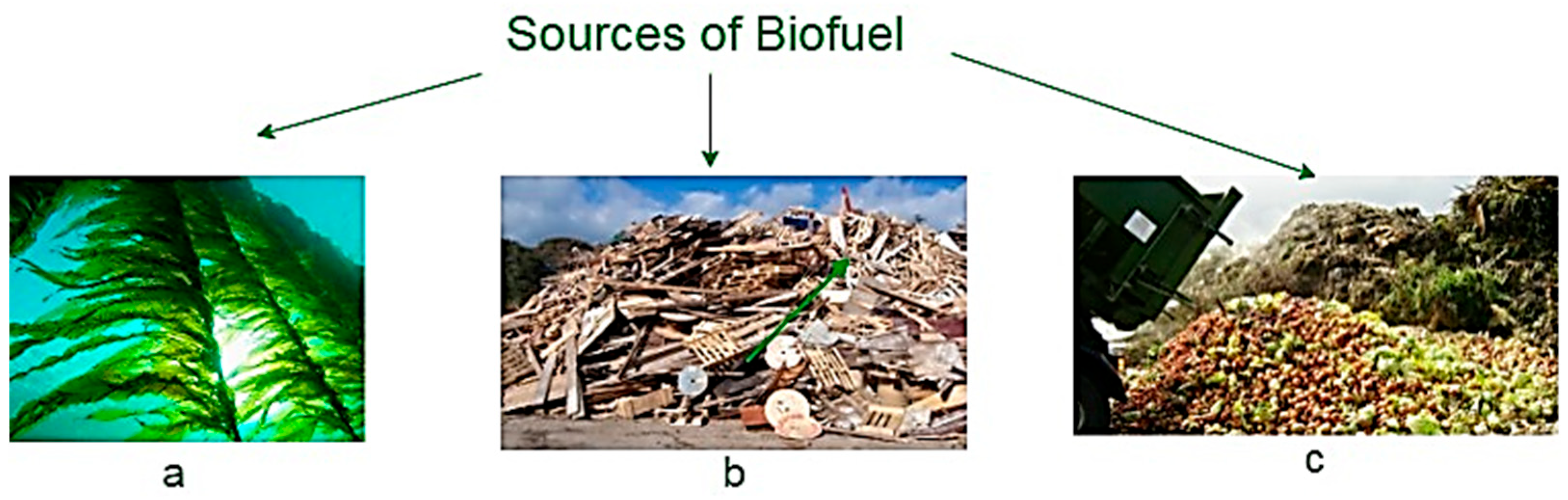
It is also known that energy can be obtained from various types of raw biomass materials, including agricultural waste, livestock waste, solid household waste, and other types of organic waste [28,29,30]. Due to a variety of processes, this feedstock can be used directly for the production of electricity or heat, or can be used for the production of gaseous, liquid, or solid fuels; biodiesel, bioethanol, and biogas are considered the most promising [31,32,33]. The most promising biogas-based fuels are hydrogen mixtures and hydrogen, which can reduce greenhouse gas emissions when replacing natural gas without changing the combustion technology [34]. Thus, pure biofuels, or, more commonly, biofuels mixed with oil-based fuels, can be used in liquid fuel systems for use in process equipment, transport, or heating. The range of bioenergy technologies is wide, and the level of their technical development varies considerably [35]. For example, according to existing research findings [36,37], the effect of hydrogen enrichment leads to a reduction in hydrocarbon emissions and soot from the gas engine and contributes to improved engine energy efficiency and fuel economy. This is particularly relevant to the Eastern Siberian Arctic area where a large number of diesel generator sets are used for heating and oil tankers run on diesel engines, i.e., the relevance of converting engines and generators to a gas-diesel format or using gas engines, in general, is increasing.
Due to its harsh climatic conditions, the Eastern Siberian Arctic is not rich in raw materials for the production of biofuels, however, this study shows non-trivial approaches to its production. In particular, among a number of suitable raw materials for the production of biofuels in the Eastern Siberian Arctic, the authors include wastes from the petroleum industry, which is further discussed below. It is worth noting that hydrogen and hydrogen-containing mixtures are quite difficult to transport and store [38], but in this case, the harsh climate conditions of the Eastern Siberian Arctic best contribute to the development of technologies for storing and transporting hydrogen in a gas-hydrate state [39].
In addition to flare gas, the petroleum industry produces large quantities of other industrial waste, i.e., oil sludge [40], as well as physically and chemically similar and unprofitable to extract and transport heavy oil. Oil sludge is a hazardous toxic waste on the one hand and a valuable energy resource on the other [40,41]. One approach to the environmentally friendly treatment of sludge is deep thermal decomposition based on the pyrolysis process [42]. Steam treatment or dissolving carbon dioxide CO2 is known to enhance the physical properties of heavy oil [43,44]. For high-viscosity oil, the degree of viscosity reduction when carbon dioxide is dissolved in it is comparable to the reduction in viscosity when exposed to heat [45]. Steam treatment in an area of permafrost can lead to serious equipment accidents [46]. It is also known that CO2 injection can accelerate biomass thermal cracking which increases the yield of gaseous pyrolysis products hydrogen and methane [47,48]. These prerequisites predetermine the need to develop a comprehensive technology for waste management, processing, and utilization in the Eastern Siberian Arctic fields, with an assessment of the energy resources obtained on the basis of known biofuel production technologies.
The authors of the study [49] predicted a serious confrontation between the green lobby, the shale industry, and the traditional oil industry in the near future. We already see signs of this confrontation in connection with the Arctic development strategy published by the European Union where there is a call for an early ban on the exploration and production of oil, gas, and coal in the Arctic [50]. Such political statements do not facilitate dialogue with supporters of a moderate transition strategy and, against the background of the European energy crisis of 2021/2022 [51,52], look unstable, since, for example, a significant share of gas imported by Europe is produced and supplied on the Yamal Peninsula, one of the key gas production centers of the Arctic Zone [53]. One of the tasks set in our study was the desire to show that confronting various energy lobbies is not mandatory and that it is necessary to find compromises, in particular, by finding and introducing innovative technologies to develop broadly, not for the sake of individual positions, but for the benefit of society. As the authors of the study [
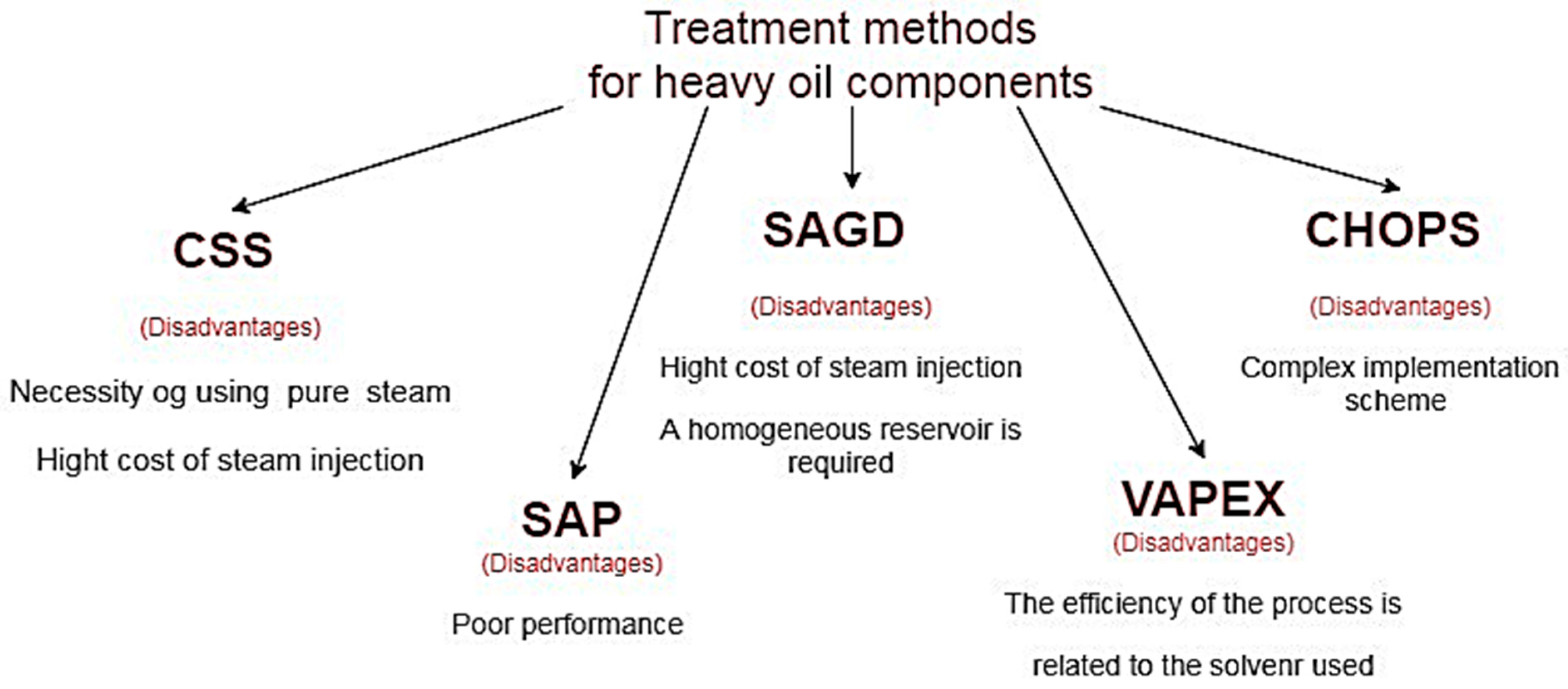
54] showed, this is especially relevant due to the increasing share of hard-to-recover hydrocarbon reserves (heavy and high-viscosity oil) widely represented in fields in the Arctic since the low temperature in such reservoirs prevents the ideal maturation of hydrocarbons. It also limits the ability to extract hard-to-recover hydrocarbons and increase oil recovery by thermal techniques which can cause permafrost melting and can lead to wellbore collapse, requiring the development of unique solutions and/or other techniques such as CO2 injection [55].
The set of non-trivial solutions presented in this study is based on the introduction of green environmental technologies into established mining processes, leading not only to a decrease in the carbon footprint but also to potential economic benefits for oil and gas companies. The main purpose of this study is to evaluate an oilfield-adapted integrated biofuel technology based on the supercritical extraction and thermal decomposition of the feedstock—waste products. The choice is justified by the analysis of the Eastern Siberian Arctic bio-resource potential stability for the region’s sustainable development.
To achieve this goal, it is necessary to present a concept for the production of biofuels on an industrial scale in the conditions of hydrocarbon deposits in the Eastern Siberian Arctic. The stage of this task was the development of technology for the production of biofuels in the conditions of the East Siberian Arctic field by adapting known methods for the production of biofuels and studying the sources of suitable raw materials. To predict the behavior of the biofuel production system in Arctic fields based on the proposed technology, the task was set to develop an experimental bench for the study of the well extraction process. The next task was to experimentally investigate the process of extracting hydrocarbon substances from heavy petroleum components by extracting carbon dioxide in a supercritical state, followed by heat treatment of the obtained substances to obtain useful products. A qualitative and quantitative composition assessment was then performed on the products obtained. In addition, one of the main tasks of this study was to demonstrate the possibilities for synthesizing existing mining technologies and green energy.

2. Development of Biofuel Production Technologies Using Supercritical Fluid Extraction

2.1. Supercritical Fluid Extraction Technology

A typical supercritical fluid extraction (SFE) scheme is shown in Figure 1 [56,57]. The main equipment of this technology include (Figure 1): cylinders with solvent, 1, and co-solvent, 2; a pressure pump, 4; extractor, 6; pressure vessel, 7; and separator, 8, where the extract is accumulated and separated.
As noted in [58], the most important condition for SFE is the choice of solvent. As the temperature rises at constant pressure, the density of the gases decreases, causing the dissolving capacity of the gases to decrease. The concentration of solute in the dense gas increases as a result of the reaction of the solvent and the increase in vapor pressure of the solute as the temperature and pressure increase. Consequently, the effect of temperature on the solubility of a substance in a supercritical fluid varies with pressure. As a rule, an increase in pressure leads to an increase in solubility. Therefore, substances with high critical temperatures are better solvents, i.e, water, than gases with low critical temperatures.
It should be noted that due to the high critical parameters (374 °C, 22 MPa) [59,60], supercritical water for industrial use is a low-attraction solvent. Therefore, the most often used solvent for SFE is carbon dioxide, since CO2 in the supercritical state is at a moderate critical temperature (31.1 °C) and pressure (7.38 MPa) [60,61]. In addition, CO2 is a non-toxic, inexpensive, and easily removable substance from the obtained extract since CO2 is in a gaseous state at room temperature [62].
The disadvantages of SFE include the complexity of manufacturing equipment for high pressures and the need to maintain the required process temperature between 35 and 90 °C [63].

2.2. Potential of Application of SFE Technology for Biofuel Production in Downhole Conditions

The described SFE technology can be adapted for the well stock of hydrocarbon deposits. Due to the fact that every year the number of abandoned oil and gas wells grows, for example, they number about 2 million in the USA alone, causing methane emissions and other environmental damage [64,65], we propose using the wells as an extractor for the production of biofuels on an industrial scale. The well can act as a natural reactor for chemical reactions and biofuel extraction.
The operation in [66] shows the parameters of temperature and pressure as well as depth increases during carbon dioxide injection. From this work, it follows that as the well is deepened, the parameters necessary for the supercritical extraction of biofuels can be obtained. It can also be noted that oil and gas well equipment is designed for high pressure and temperatures [67].
Figure 2 shows the developed conceptual technology of the downhole extraction process with flare gas utilization.
Flare gas in oil and gas fields can be collected and moved by means of water-ring compressors [68] or ejectors [69].
The next stage of biofuel production technology is the supply of flare gas to the power generation and cogeneration plants, as well as to the ammonia production plant based on the Gaber process, the possibility of which is described in [70]. At the same time, flare gas energy is converted into electricity and heat in power generation and cogeneration plants, respectively. When the produced electricity and heat are supplied to the ammonia production plant based on the Gaber process, the following products useful for technology are obtained [71]: ammonia, 2NH3, and high purity CO2, carbon dioxide. The obtained ammonia can be supplied to the annular well space for heating the tubing string and its contents.
The resulting CO2 and biofuel feedstock can be stored in pressurized tanks at 0.8 MPa [72]. CO2 can also be stored in liquid form at a temperature of approximately −18…−24 °C. Negative temperatures in the northern and Arctic territories can be achieved naturally in winter, and in summer by using a refrigeration unit consisting of compressors and refrigerant condensers. Heat stabilizers with forced circulation may be an alternative to refrigeration units. To date, thermal stabilizers are used to cool the foundations of oil tanks in the northern fields, for example, at the Vankor field [73]. The insulation addition cooling system can minimize operating costs and reduce CO2 losses resulting from evaporation due to pressure and temperature differences, such as through valve devices. Usually, before being fed into the tanks, CO2 is dewatered when its dew point drops to below 0 °C and compressed to critical pressure [74]. Underground CO2 storage can also be used in combination with terrestrial tanks [75].
The feedstock and CO2 can be sequentially pumped into the tubing column by means of a Christmas tree, which thus acts as an extractor. In this case, CO2 is brought to a supercritical state by pre-compression, or sequential injection into the tubing column or throttling, as well as heating, using heating inserts, NH3, or a set of methods.
A further step is the phase separation of the extract and, depending on the raw material used, it can be either separation, heat treatment, or a set of methods. In particular, when using raw hydrocarbon materials, i.e., oil sludge, extract can be decomposed by thermal destruction methods into hydrocarbon gases and then into pure hydrogen, which can be carried out using one sectional pyrolysis plant [76]. Thus, we find the technology of the fixated production of biofuels at the existing injection or abandoned (liquidated) wells with the disposal and/or use of waste produced in the form of flare gases and heavy oil.
Today, there is the practical experience of CO2 injection into the oil reservoir and when developing this technology, it is necessary to take into account this practical experience [77].
Table 2 shows the recommended materials for CO2 injection [78].

2.3. Overview of Raw Materials for Biofuel Production in the Eastern Siberian Arctic

Next, we will review the most common raw materials in terms of energy potential for biofuel production in the Eastern Siberian Arctic.
We divided the most common raw materials into groups (Figure 3).
  • The energy potential of biological objects such as corn, soybeans, algae (Figure 3a), etc. This raw material group for biofuel production is quite stable in terms of cheapness, high biomass accumulation, and rapid reproduction as well as the global property qualities of the resulting fuel [79] or its potential [80], to a greater or lesser extent, depending on specific raw material, i.e., it allows cyclically growing and obtaining energy, reducing negative impacts on the ecosystem and replacing traditional energy sources [81]. Oil extracts obtained from the presented raw materials can be converted to bioethanol [82] and biodiesel [83]. Highly productive energy plants such as Jatropha curcas [84] do not survive in the Eastern Siberian Arctic due to harsh soil and climatic conditions. In the south of the region, experiments have been conducted to create fast-growing transgenic plants based on aspen and poplar [85,86]. However, the industrial cultivation of transgenic plants in the Russian Federation is prohibited.
  • Pulp (fiber), wood, and paper waste (Figure 3b) as raw materials. Fiber is found in the stems of plants and trees [87]. Thus, in order to obtain biofuels, fiber can be produced and processed, which makes it possible to establish an almost continuous technological process. Waste from wood processing also contains fiber and can be used to produce biofuels. Bioethanol is mainly obtained from fiber [88].
  • For the Eastern Siberian Arctic, we identified raw materials such as the by-products of enterprises and human activities (emissions and waste) as well as yedoma (Figure 3c). In particular, both independent gases (methane, hydrogen, etc.) and those obtained by the processing of certain raw materials can be used as biofuels (biogas). For example, organic waste under the influence of certain microbes decomposes to form methane gas, which can be collected for further use [89]; when the produced gas is ignored, a greenhouse effect is formed.
Thus, the most interesting process includes the processing of hydrocarbon and household waste, which we also divided into three groups.
The first group includes used oils and lubricants [90,91], i.e., oil spills, emulsions, and heavy oil components which cannot be mined or processed by conventional methods [92]. Every year the number of abandoned wells increases, due to the heavy and contaminated residue of raw oil materials which is difficult to produce and transport [93]. Meanwhile, the wells are preserved and heavy oil fractions can be used as feedstock for biofuel production. Different emulsions formed during oil storage and oil spills are classified as oil sludge, from which, with proper processing, it is possible to obtain different types of biofuels.
The second group includes solid household waste consisting of organic materials [94]. The advantage of using this kind of raw material lies in the possibility of controlling the final product (from gases to liquids and solid residues). In particular, it is possible to obtain hydrogen [95], which, when burned, forms only water, making this type of fuel environmentally friendly.
The third group includes raw materials such as yedoma. Frozen yedoma is the relict soil of the giant steppe-tundra ecosystem which occupied the territory of Siberia, Alaska, and part of Canada in glacial times [96]. Yedoma is essentially an organic material consisting of dead plants, animals, and microbes that has not broken down and accumulated carbon for thousands of years [97]. The main danger of yedoma to the ecosystem is the production of greenhouse gases, methane, carbon dioxide, and nitrous oxide, which are formed when the temperature of yedoma increases past the freezing point. At the same time, the organic part of yedoma can be of practical interest for processing, by drilling wells and collecting and processing organics [98,99].
Thus, some non-trivial ways of using raw materials for biofuel production for the sustainable development of the north of the East Siberian region are discussed, often requiring the development of appropriate technologies for the production of raw materials and biofuels themselves, characterized by minimal environmental impact.

2.4. Review of Impact Methods on Heavy Hydrocarbon Well Fractions for Biofuel Production in the Eastern Siberian Arctic

There are many methods to date for handling downhole heavy organic components (the raw materials of the first group mentioned above). We are interested in the possibility of using these wastes of production for extraction and subsequent processing. The most common methods of manipulating heavy borehole fractions of hydrocarbons include:
  • Cyclic Steam Stimulation (CSS). This method consists of the periodic (pumping-stopping-pumping) injection of hot steam into heavy oil deposits or oil sand deposits through the common well bore with subsequent recovery of hydrocarbons [100]. The disadvantages of this method of oil displacement by steam include the need to use high-quality clean water for steam generators [101] in order to obtain high-quality steam with a saturation of 80% and a heat capacity of 5000 kJ kg.
  • Steam-Assisted Gravity Drainage (SAGD). This is a widely used method designed to extract heavy oil components [102]. The difference between the SAGD method and the CSS method is the drilling of two horizontal wells parallel to each other. The distance between the wells is usually about 5 m, and the length of the horizontal shafts is 1000 m. The main drawback is the high cost of oil production by this method [101].
  • Cold heavy-oil production with sand (CHOPS). This method consists of the complex extraction of oil, together with sand, by the destruction of the weakly cemented reservoir and the creation of appropriate formation conditions for the flow of a mixture of oil and sand [103]. To implement this method, it is necessary to use a well injection scheme that promotes the flow of sand, in addition, there must be enough dissolved gas in the formation to maintain formation energy.
  • Vapor Extraction (VAPEX). In this method, two horizontal injection and production wells are used. Hydrocarbon gases (propane, methane-propane, or propane-butane) are generally used as the solvent. The reduction in the viscosity of heavy oil is achieved due to heating and dilution with solvent resulting in a mixture of bitumen-solvent that flows down into the production well [104] by gravity. VAPEX assumes the following initial conditions: the thickness of the productive formation is more than 12 m; bitumen viscosity in formation conditions is more than 600 mPa s; horizontal permeability is greater than 1000 μm2; and vertical permeability is 200 μm2. According to the authors of the study [105], the disadvantage of this method is its low performance.
  • Solvent Aided Process (SAP). In this method, a small amount of hydrocarbon solvent is added as an additive to steam pumped using SAGD technology [106]. While steam is the main coolant and reduces the viscosity of the oil, the addition of solvent contributes to its thinning to an even greater extent. The main disadvantage is the partial loss of solvent that will remain in the well during its injection.
A brief description of the disadvantages of the methods discussed is presented in Figure 4.
The most popular method, according to the researchers [105,107] and the authors of this study, is the VAPEX method. With the discovery of using CO2 as a solvent, it became possible to increase efficiency and reduce the cost of maintaining the VAPEX process [108], as well as ensure its safety [109], which makes this method more attractive for implementation [110]. In addition, the use of the supercritical state of CO2 obtained by supercritical liquid extraction methods allows not only the softening of heavy oil components to facilitate transportation but also their preparation for subsequent processing directly at the production site.

3. Methodology and Materials of Experimental Studies of Biofuel Production in Downhole Conditions

3.1. Raw Materials

To study the extraction process, samples of heavy oil components of the Vankor field of the Krasnoyarsk Territory were used as raw materials. They are a dark brown physicochemical mixture, consisting mainly of petroleum products, with a water content of about 9%, and mechanical inclusions of less than 1% (Figure 5).
The main properties of the raw materials used are shown in Table 3.

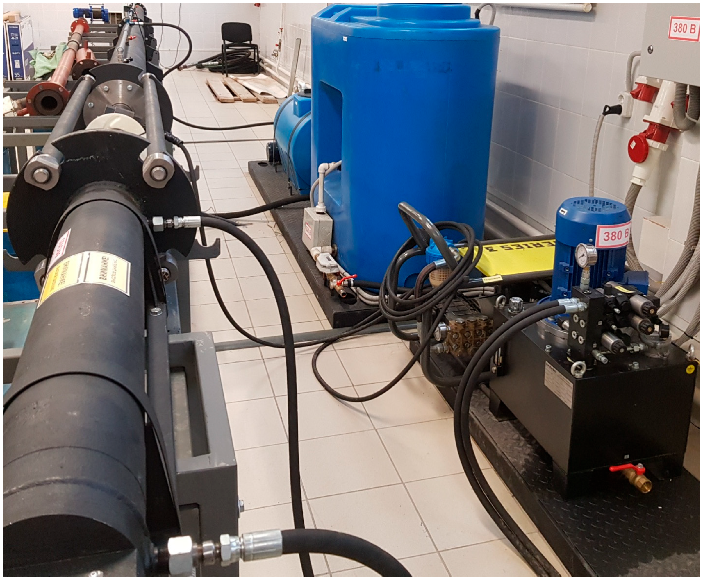
3.2. Purpose and Functions of Borehole Extraction Test Bench

The test bench (Figure 6) was designed for the testing process operations of the extraction method in biofuel production and includes a process control system.
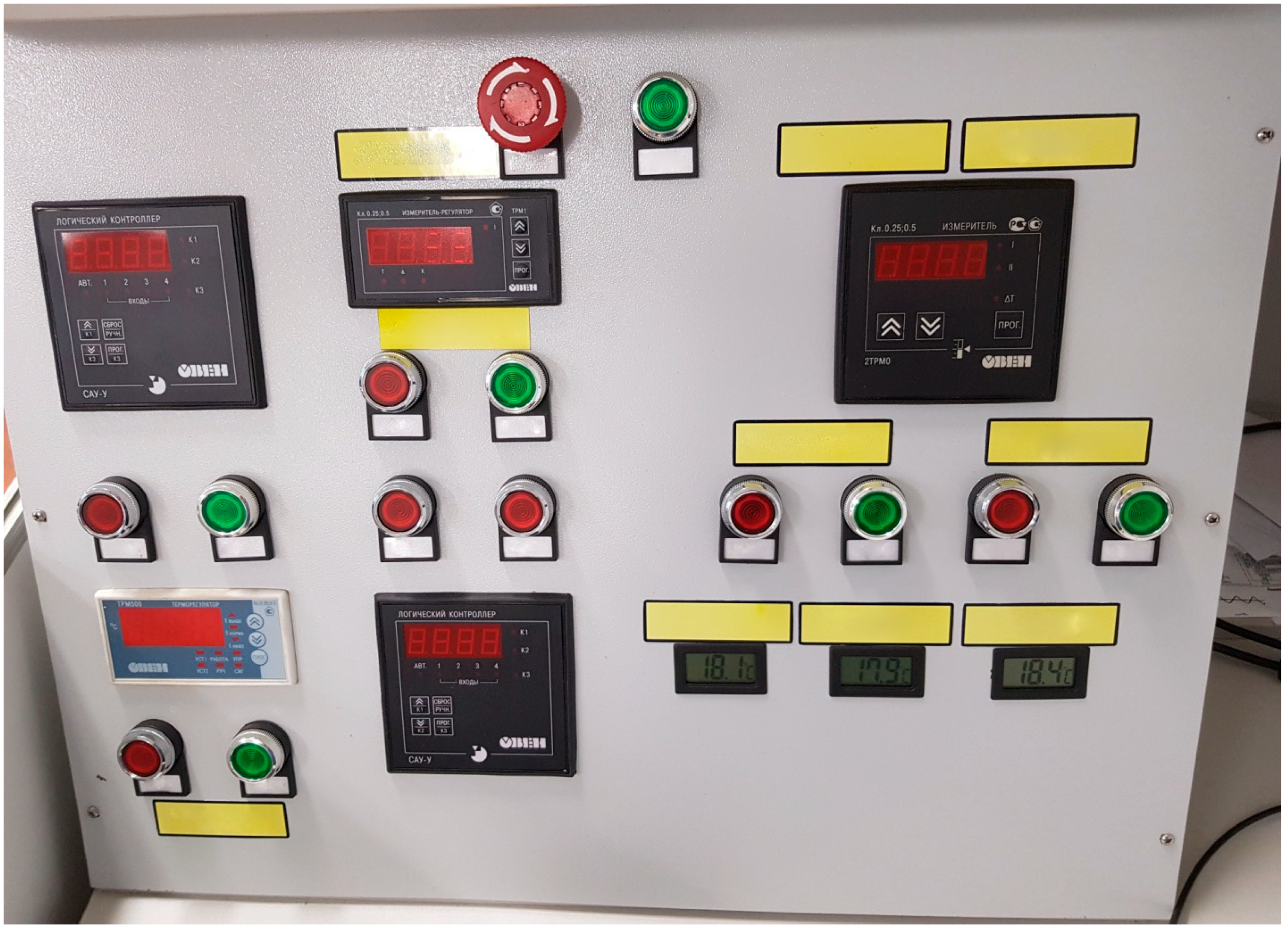
The bench was designed to investigate the parameters of the extraction process in the well casing using tubing, as well as methods of obtaining and processing information about these processes using the operator console (Figure 7) and PC with the aim of further modeling and forecasting the parameters of the extraction process.
The bench is a collection of hardware, process control, monitoring tools, measuring sensors, steel structures, and software.
The bench provides the following process functions:
-
Ability to test extraction process operations in biofuel production in close to actual well process conditions.
-
Tests of the extraction process system at the specified physical parameters including the pressure of the injected process liquid and the flow rate (or volume flow rate) of the process liquid.
-
Possibility of supercritical CO2 production by compression.
-
Display of process progress information, i.e., process parameters and equipment states, on the operator console.
-
Remote control of technical devices from the operator console.
-
Transfer of stand parameters to the database.
-
Emergency disconnection of all technical devices and devices to ensure safety in case of emergency situations.

3.3. Installation of Test Bench for Testing of Borehole Extraction Processes
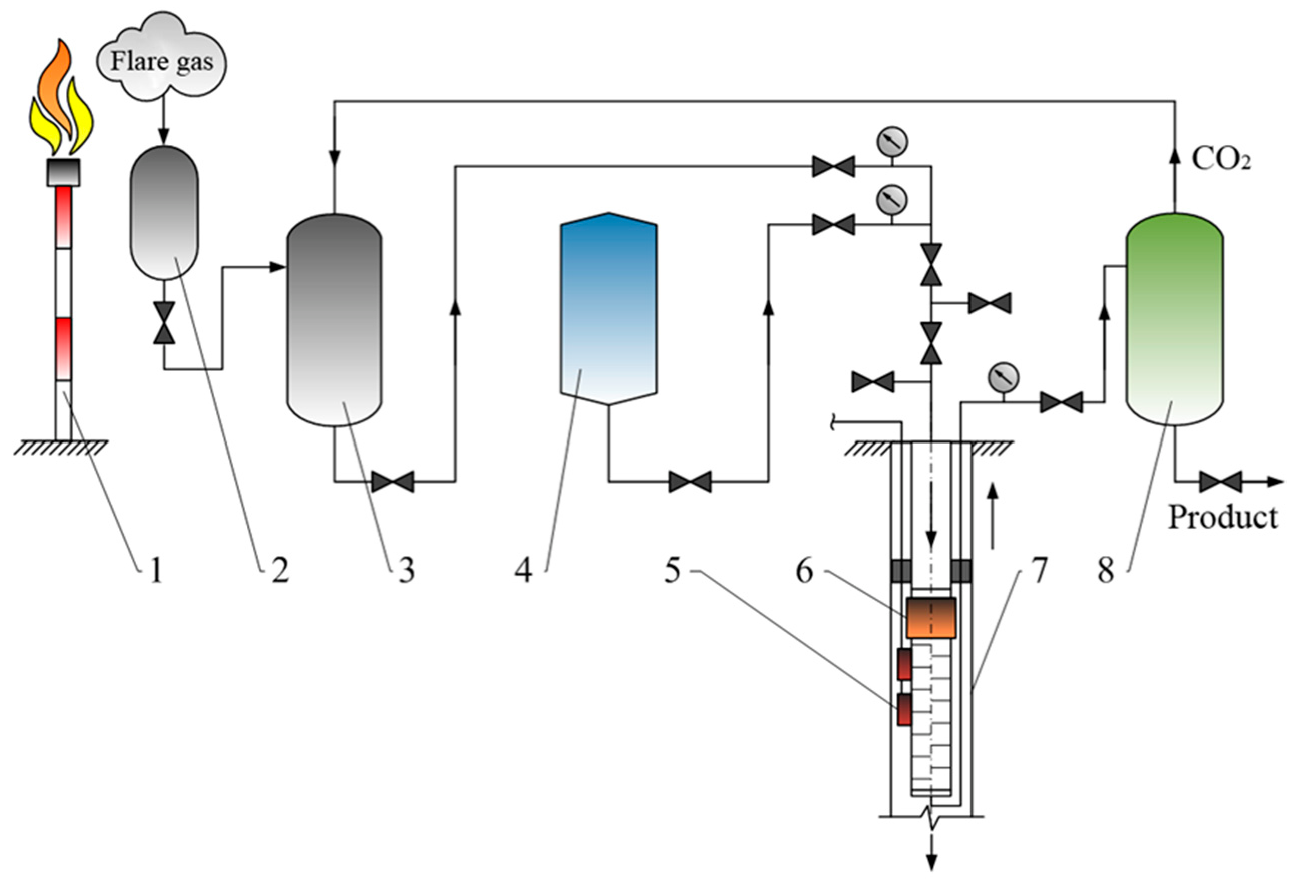
The stand (Figure 8) consists of four units: I is hydraulic station of the hydraulic cylinder; II is well simulator; III is high-pressure hydraulic station; and IV is tank farm.
Pump station W-1 feeds a two-way hydraulic cylinder 2/1. Hydraulic cylinder 2/1 is mechanically connected to tubing 2/2 in casing 2/3.
The high-pressure station W-2 provides an injection of process fluid into tubing 2/2. Tubing string 2/2 has windows (through holes) that open in casing string 2/3 when hydraulic cylinder 2/1 moves together with pipe 2/2 to the right. The piston is installed on tubing 2/2 (not shown conventionally).
The bench is equipped with a 1 m3 4/1 flow tank and a 0.25 m3 4/2 drain tank. Pumping of liquid from drain tank 4/2 to flow tank 4/1 is performed by drain pump 4/4. Tank 4/1 is equipped with a system of automatic heating of the process fluid 4/5 and a circulation pump 4/3 for medium temperature averaging. The centrifugal pump-compressor used 4/8 to pump liquid or gas into casing 2/3.
All hydraulic systems are equipped with valves (positions “B” in the diagram of Figure 8). Pressure in hydraulic systems is controlled by pressure gauges. The volume of liquid flow is controlled by an ultrasonic flowmeter 4/6. Tanks 4/1 and 4/2 are equipped with level indication devices 4/7. Test bench monitoring devices and controls are reduced to the operator panel.
Grades and models of the main equipment used and equipment of the bench are summarized in Table 4.
Controlled bench parameters:
-
Pressure levels of hydraulic supply systems of the hydraulic cylinder and high-pressure station of process fluid supply;
-
Operating medium temperature in the service tank;
-
Liquid levels in the flow and drain tanks;
-
Critical level of liquid in the service tank;
-
Ambient temperature of the bench location at three measurement points;
-
Process fluid flow volume by ultrasonic flowmeter;
-
Availability of power supply on electric motors of pumps;
-
Control of the linear stroke of the hydraulic cylinder rod.
The dispatching and monitoring of system operation parameters are organized on the operator console.

3.4. Operation of the Stand

Process sequence on the bench:
(1)
Feed to tubing 2/2;
(2)
Supply of solvent (supercritical CO2) prepared in advance in consumption tank 4/1 to casing 2/3;
(3)
Mixing of raw material and solvent by the movement of hydraulic cylinder 2/1 with tubing 2/2 to the right. At the same time, pressure increases due to the piston installed on the tubing;
(4)
Maintenance and production of extract;
(5)
Opening of valve B2/4 and overflow of extract into drain tank 4/2.
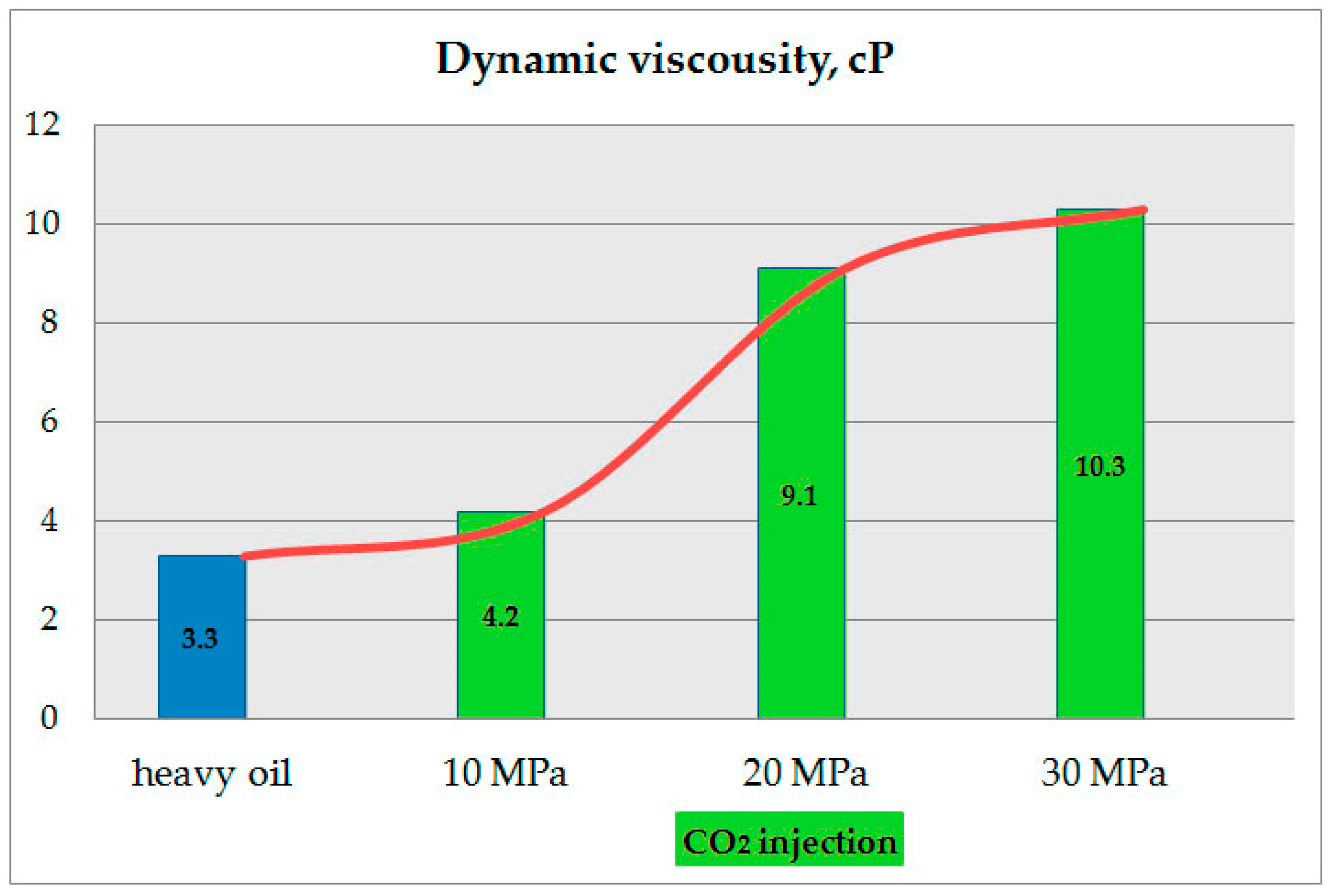
Heavy oil extraction efficiency was analyzed by assessing the viscosity of the residual oil. The residual oil is the oil immobilized after the extraction process. CO2 dissolution was carried out at a pressure of 10, 20, and 30 MPa. Residual oil sample viscosity was measured at 30 °C using a Brookfield rotary viscometer CAP-1000+.
To produce biofuels, the obtained extract is treated by thermal methods. In our case, the process of low-temperature destruction was used.

3.5. Processing of the Hydrocarbon Component of the Obtained Extract

The process of low-temperature destruction (distillation) was carried out in reaction equipment at a temperature of 550 ± 20 °C and atmospheric pressure. The process of destruction itself was divided into two stages:
  • The organic part of the extract is distilled to produce hydrocarbon gases and the raw material is held in the reaction zone for 10, 20, and 30 min.
  • The production of hydrogen by the reaction of light hydrocarbons with a catalyst. The duration of the process was determined by reducing the amount of hydrogen produced. The process was carried out in the temperature range of 550 to 650 °C.
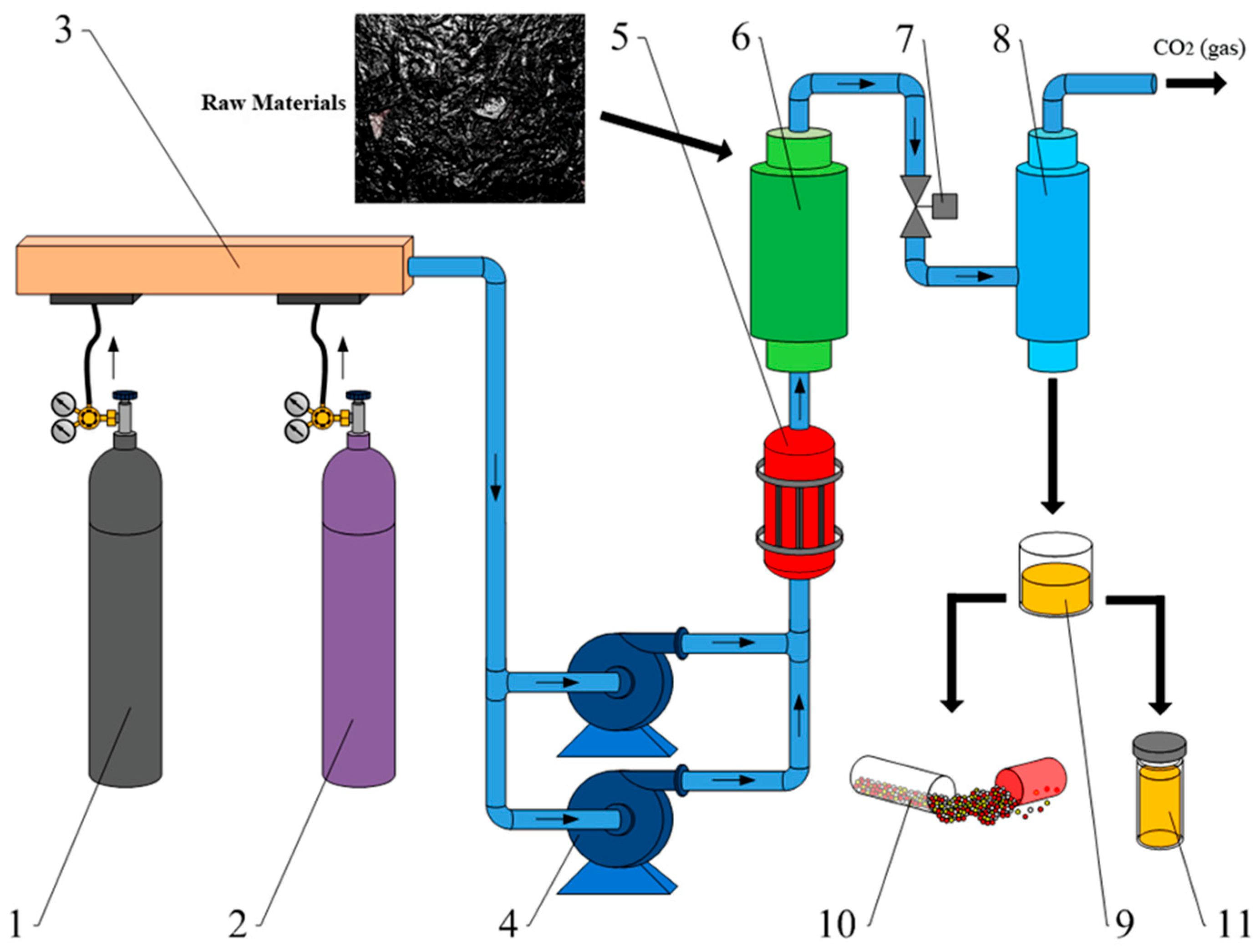
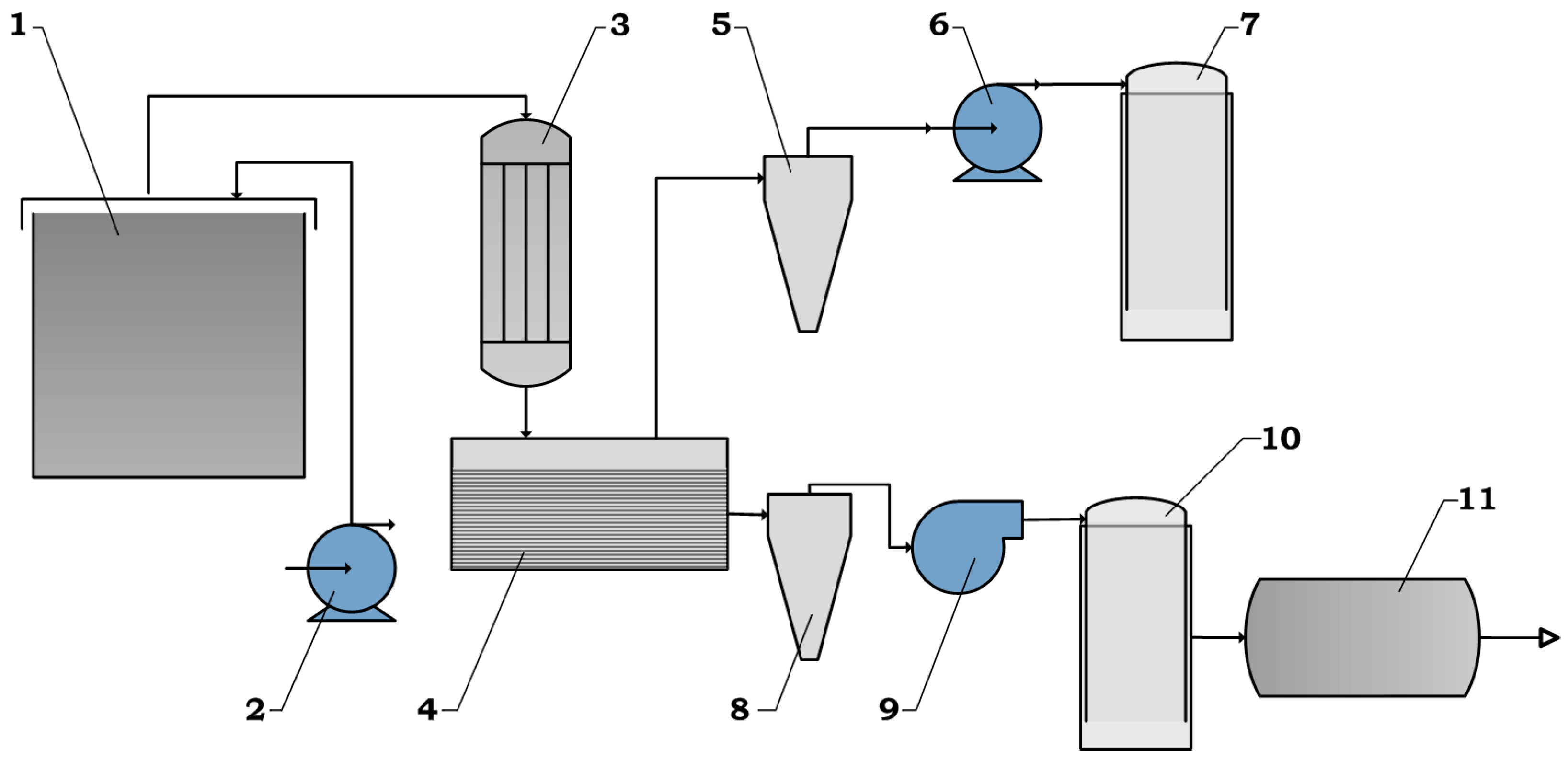
The experimental bench for processing the hydrocarbon component of the obtained extract is shown in Figure 9.
The stand works as follows:
The obtained extract is fed to pyrolysis reactor 1 by means of pump 2. The heaters provide the necessary amount of heat to start the destruction process. Thermocouples monitor the temperature parameters. The heat-insulating material retains heat in the reactor, thereby reducing energy costs to maintain the pyrolysis process.
The released reaction products are fed to heat exchanger 3 to separate the liquid and gaseous pyrolysis products. Then, they enter settling tank 4, where, by means of pump 6, liquid products pass through the hydrocyclone 5 and enter receiver 7 for temporary storage.
In turn, the gaseous products, by means of the high-pressure fan 9, pass through cyclone 8 and enter the sampler 10.
In order to obtain hydrogen, the remainder is sent to reactor 11 for processing.
The “Clarus 600” chromatograph was used to measure the concentration of gaseous hydrocarbons in the gases generated by the distillation of hydrocarbons produced by the extraction of heavy petroleum components formed in the first stage. The chromatographic condition is shown in Table 5.
The catalytic pyrolysis method was used to decompose the gasified oil pyrolysis product, methane. Proven effective in previous hydrogen production, high-percentage nickel catalysts were used [111]; they are characterized by a high product yield efficiency and low cost compared to catalysts containing noble metals.
The amount of hydrogen released was determined using the ”EMIS VIKHR 200” (EMIS, Russia) vortex flowmeter.
The lowest combustion heat of the resulting hydrocarbon gas mixture was determined using a flow gas calorimeter Rhadox 7300 (“AMS Analysen-, Mess- und Systemtechnik GmbH”, Dielheim, Germany).

4. Results and Discussion

The main result of the laboratory studies was confirmation that the developed biofuel production technology works under borehole conditions. In particular, a number of technological processes were successfully tested in the laboratory facilities developed, namely:
  • Supercritical heavy oil extraction technology adapted to downhole conditions;
  • Thermal destruction technology of carbonated oil including mode parameter development (reaction times) to determine optimum conditions for the process;
  • Catalytic pyrolysis technology for the thermal degradation product of carbonated oil and hydrocarbon gases, determining different catalysts’ effect on hydrogen yield.
Research results on these processes are explored consistently in this section.
The results of the residual oil viscosity change after exposure to CO2 at 10, 20, and 30 MPa compared to the viscosity of unexposed oil are shown in Figure 10.
According to the results (Figure 10), higher pressure increases the solubility of CO2 in heavy oil. Significant results are obtained at a pressure of 20 MPa. However, data obtained at 30 MPa indicate that the trend in residual oil viscosity with increasing pressure is likely to have a rapid limit, i.e., further pressure increases are ineffective, requiring additional residual oil operations such as repeated extraction or additional heating. Dissolving CO2 increases the proportion of light hydrocarbons, mobilizing them and overcoming heavy oil’s low mobility. CO2 extraction thus contributes to raw materials’ manageability, in particular, their transportability. It should be noted that the maximum working pressure of most tubing types exceeds 25 MPa.
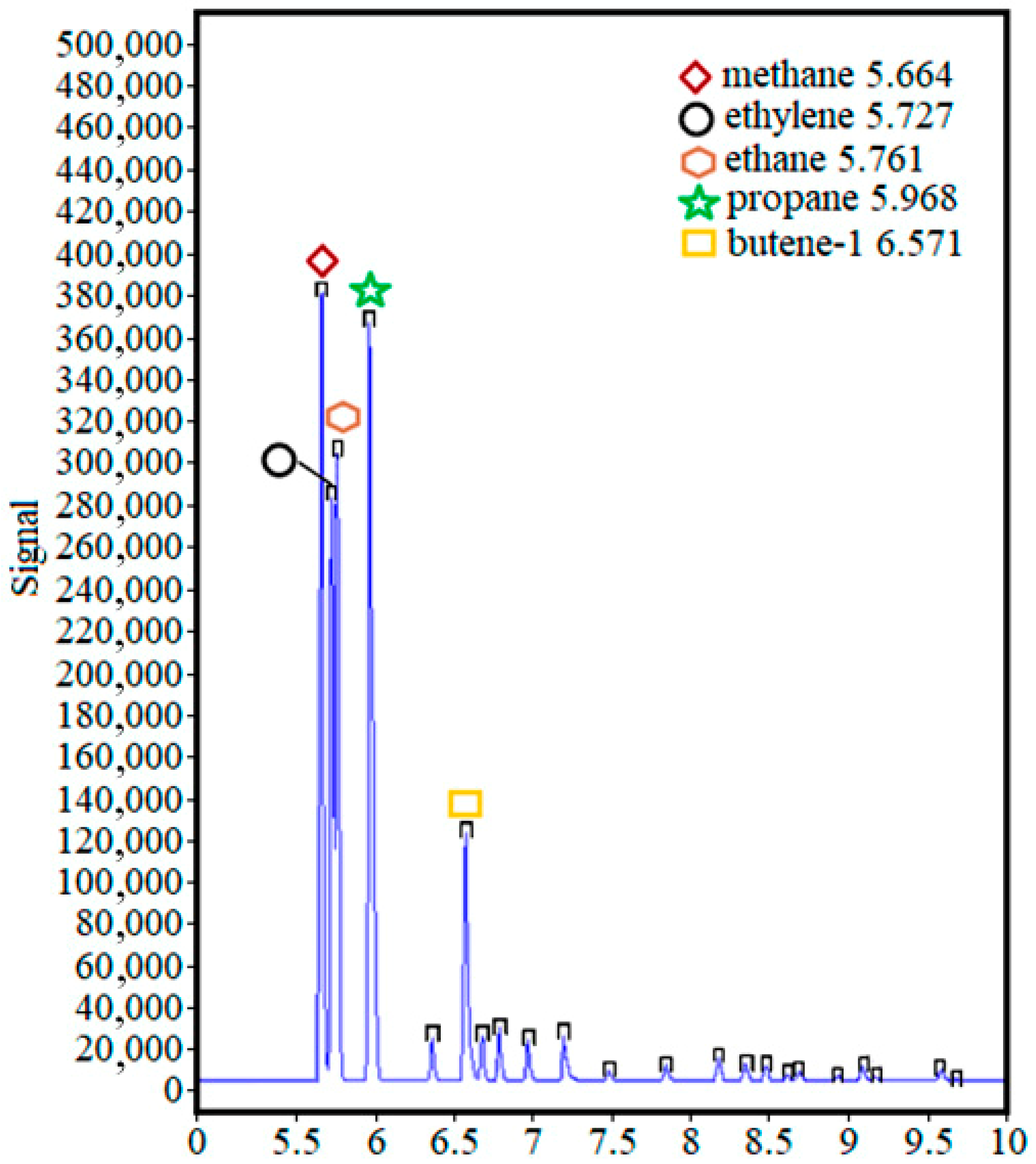
The results of the chromatographic analysis, in the first step, show that with an increase in the residence time of the feedstock, from 10 to 20 min in the reaction chamber, the total concentration of light hydrocarbons increases (Table 6 and Table 7).
A longer residence time of up to 30 min resulted in a decrease in the total concentration of the gaseous fraction (Table 8).
This can be explained by the conversion of minor organic products to significant ones by chemical interaction at a given temperature (recorded by chromatographic analysis) as well as losses.
The main components of the gas fraction were methane (CH4), ethylene (C2H4), ethane (C2H6), propane (C3H8), and butylene (C4H8). In the entire range of holding time, only their percentage changed (Figure 11).
Thus, a suitable holding time was about 20 min (ranging from 20 to 30 min). At the same time, it should be understood that increased residence time leads to increased energy consumption, which can affect the efficiency of the process, thereby spending more energy than is obtained. At the same time, the concentration of the remaining hydrocarbons was below 0.5%, or traces were observed.
In addition to the formation of gaseous products, liquid hydrocarbons and a solid residue are also formed. The liquid fraction consisted of saturated, unsaturated, cyclic, and aromatic hydrocarbons. In turn, the solid fraction consisted of coke; the combustion of which produced ash. The present paper did not examine the liquid and solid fractions, but only determined their quantitative distribution. Therefore, the distribution of fractions during distillation was as follows: 60%—liquid, 20%—gaseous, and 20%—solid, with an error of ±2%.
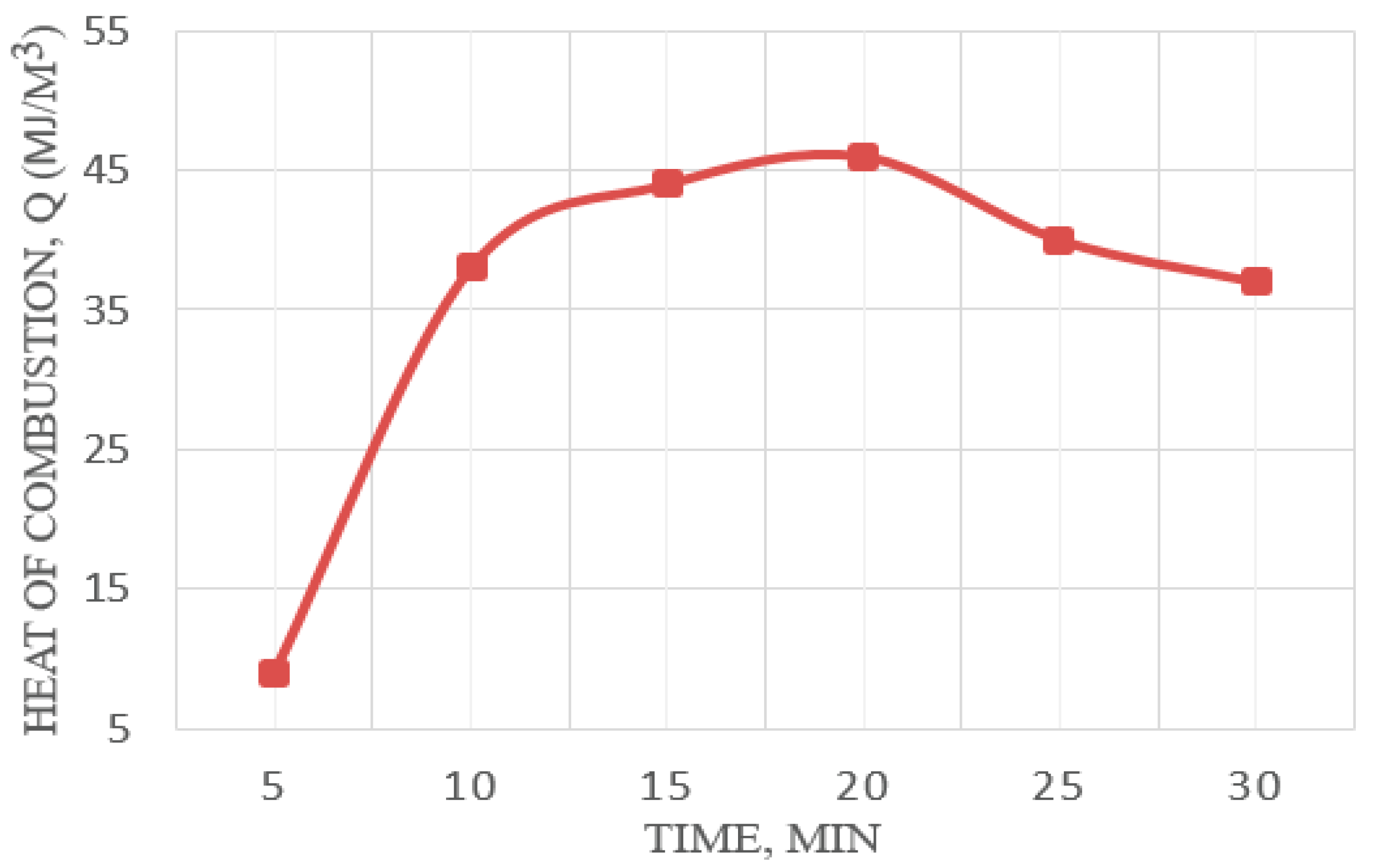
In addition to the quantitative characterization of the formed light hydrocarbons, a qualitative assessment of the gaseous pyrolysis products was carried out. For this purpose, the heat of combustion of the gas and the mixture was determined. The kinetics of combustion heat change for pyrolysis gaseous products at 550 °C is shown in Figure 12.
As a result of the calorimetric analysis, it was found that the lowest combustion heat of the resulting gas mixture reaches its maximum value at around 20 min (Figure 12). Further holding time leads to a gradual reduction in the combustion heat value, i.e., the calorific gas value is reduced. This phenomenon can be explained by a deeper breakdown of hydrocarbons and an increased yield of low-molecular-weight gaseous products. The combustion heat measurement error was ±1.52%.
As mentioned above, in the second step, light hydrocarbons are converted to hydrogen by reacting with the catalyst. To do this, the distillation products were discharged from the reaction apparatus, the catalyst was charged, and by running the gas fraction (methane) in the presence of a catalyst, a process of hydrogen formation took place and the carbon nanomaterials were formed.
The results and catalysts used are shown in Table 9.
The obtained hydrogen yield of the test extract ranged from 44 to 118 L/h depending on the catalyst (Table 9). As can be seen from the results, with an increase in the process temperature, there was a roughly twofold increase in the hydrogen yield. This is explained, as in the previous case, by deeper conversion of raw materials. Additionally, with an increase in the reaction temperature, an increase in the residual methane content of the reaction products was observed. Furthermore, the increase in temperature affects the effective operation time of the catalyst, leading to its faster deactivation. Further adsorption of methane can be carried out on carbon plates in order to separate the gas fraction.
According to Table 9, the nickel-based catalyst on aluminum oxide had the lowest hydrogen yield. The low efficiency of the monometallic catalyst in gaseous hydrocarbon decomposition can be explained by its rapid deactivation. It can be due to the catalyst’s low active metal content, and the use of aluminum oxide as a carrier which, in its turn, has weak acidic properties and can itself take part in the chemical reaction leading to by-product formation. The nickel catalyst with silicon dioxide has the highest hydrogen production efficiency. It contains a larger amount of active metal and uses silicon dioxide as a carrier. Silicon dioxide, compared to aluminum oxide, has a higher specific surface area and is characterized by greater inertness towards the active metal deposited thereon.

5. Conclusions

  • The sustainability of the Eastern Siberian Arctic is highly dependent on the region’s energy sector processes. The remoteness and climatic conditions of the region make it unique and limit its sustainable development, significantly narrowing the scope for renewable energy in particular. The deep and expanding oil and gas industry poses new risks, challenges, and opportunities for the region’s development. A large amount of oil industry waste raised an acute environmental issue in the region. In the future, due to the need to ensure special environmental safety measures, this can negatively affect the economic and political development of Russia and beyond. These conditions require the development of new unique solutions equal with the Paris Climate Agreement and other global regulatory documents.
  • One of the solutions was given to us by the fact that Russia is the leader in the emissions of flare gases, a significant part of which are hydrocarbon production and processing enterprises. We saw relevance in the use and disposal of these gases, as industrial waste, with a concurrent decrease in the carbon footprint. In particular, flare gases can be used after processing as a solvent for another industrial waste, heavy oil, for its recovery and subsequent creation of biofuel compositions based on it, which is also relevant for oil sludge.
  • According to the review results of potential raw materials for biofuel production in the Eastern Siberian Arctic, apart from the petroleum industry waste, there is yedoma whose energy potential is yet to be developed. The review of petroleum stimulation technologies, particularly VAPEX, confirms the feasibility and indicates how to effectively manage heavy oil or oil sludge by means of CO2 extraction.
  • Well extraction technology has been proposed for biofuel production by extracting heavy oil or oil sludge with supercritical carbon dioxide derived from flare gases. A conceptual process diagram of the downhole extractor for the production of biofuels on an industrial scale has been developed. The main stages of biofuel production technology adapted to downhole conditions are flare gas capturing; carbon dioxide recovery from flare gases; bringing carbon dioxide to a supercritical state in the well; the carbon dioxide extraction of heavy oil or oil sludge in the well; and thermal decomposition stages of carbonated oil by pyrolysis methods.
  • Tests of the biofuel production technology adapted to downhole conditions were successfully carried out on the presented specially designed laboratory benches for three successive technological processes of the technology: CO2 heavy oil extraction; thermal decomposition of carbonated oil by low-temperature pyrolysis methods; and thermal decomposition of the low-temperature pyrolysis product using the gas fraction by catalytic pyrolysis method.
  • Assessing the effectiveness of carbon dioxide extraction of the Vankor field heavy oil in adapted field conditions was evaluated by analyzing the dynamic residual oil viscosity at gas pressures of 10, 20, and 30 MPa. The result shows that CO2 actively mobilizes heavy oil and can act as a useful tool for feedstock management. Carbon dioxide’s solvent efficiency growth peaks at about 20 MPa, after which, it rapidly drops.
  • The qualitative and quantitative evaluations of formed light hydrocarbons in carbonated oil low-temperature pyrolysis were performed using calorimetric and chromatographic analysis methods. The present paper did not examine the liquid and solid fractions, but only determined their quantitative distribution. Therefore, the distribution of fractions during distillation was as follows: 60%—liquid, 20%—gaseous, and 20%—solid. The main components of the gas fraction were methane, ethylene, ethane, propane, and butylene. Thus, a suitable holding time was about 20 min (ranging from 20 to 30 min). At the same time, it should be noted that increased residence time leads to increased energy consumption, which can affect the efficiency of the process, thereby spending more energy than is obtained. The lowest combustion heat of gaseous pyrolysis products achieves its maximum value around 20 min. Further holding time leads to a lower calorific gas value.
  • The catalytic pyrolysis of gaseous products (methane) obtained as a result of low-temperature pyrolysis was carried out using nickel catalysts of different compositions at temperatures between 550 and 650 °C. Aluminum oxide and silicon dioxide were used as the catalyst carriers and the results were assessed by hydrogen yield. The obtained hydrogen yield of the test extract ranged from 44 to 118 L/h. With an increase in the process temperature, there was a roughly twofold increase in the hydrogen yield. The nickel catalyst with silicon dioxide had the highest hydrogen production efficiency.
  • The proposed technology will allow for the extraction of biofuels on an industrial scale with application in liquidated and injection wells, solving problems of environmental safety, and involving waste of the oil and gas industry in the process of biofuel production. This novel project requires further research and, in particular, an assessment of the economic costs of its implementation, taking into account both market and non-market ecosystem benefits.

Author Contributions

Conceptualization, K.A.B., O.A.K. and V.V.B.; methodology, K.A.B., O.A.K., V.V.B., V.S.T. and V.V.K.; validation, K.A.B., O.A.K. and V.V.B.; formal analysis, K.A.B., O.A.K. and S.O.K.; investigation, K.A.B., O.A.K., S.O.K. and V.S.T.; resources, K.A.B., O.A.K., S.O.K. and V.V.K.; data curation, R.B.S., V.S.T. and V.V.B.; writing—original draft preparation, K.A.B., O.A.K. and E.V.T.; writing—review and editing, K.A.B., O.A.K., R.B.S. and E.V.T.; visualization, K.A.B., O.A.K., V.V.K. and S.O.K.; supervision, K.A.B., V.V.B. and V.S.T.; project administration, V.V.B. and K.A.B.; and funding acquisition, V.V.B. All authors have read and agreed to the published version of the manuscript.

Funding

The studies were carried out according to the state assignment from the Ministry of Science and Higher Education of the Russian Federation for the project “Development of a set of scientific and technical solutions in the field of creating biofuels and optimal biofuel compositions, providing the possibility of transforming consumed types of energy in accordance with trends in energy efficiency, reducing the carbon footprint of products and using alternative fuels to fossil fuels” (Contract FSRZ-2021-0012), in the scientific laboratory of biofuel compositions of the Siberian Federal University, created as part of the activities of the Scientific and Educational Center “Yenisei Siberia”.

Institutional Review Board Statement

Not applicable.

Informed Consent Statement

Not applicable.

Data Availability Statement

Not applicable.

Conflicts of Interest

The authors declare no conflict of interest.

References

  1. Al-Rubaye, H.; Smith, J.D.; Zangana, M.H.S.; Nagapurkar, P.; Zhou, Y.; Gelles, G. Advances in Energy Hybridization for Resilient Supply: A Sustainable Approach to the Growing World Demand. Energies 2022, 15, 5903. [Google Scholar] [CrossRef]
  2. Jing, R.; Lin, Y.; Khanna, N.; Chen, X.; Wang, M.; Liu, J.; Lin, J. Balancing the Energy Trilemma in Energy System Planning of Coastal Cities. Appl. Energy 2021, 283, 116222. [Google Scholar] [CrossRef]
  3. Kang, H. An Analysis of the Relationship between Energy Trilemma and Economic Growth. Sustainability 2022, 14, 3863. [Google Scholar] [CrossRef]
  4. Erickson, L.E. Reducing Greenhouse Gas Emissions and Improving Air Quality: Two Global Challenges. Environ. Prog. Sustain. Energy 2017, 36, 982–988. [Google Scholar] [CrossRef] [Green Version]
  5. Chanysheva, A.; Ilinova, A. The Future of Russian Arctic Oil and Gas Projects: Problems of Assessing the Prospects. J. Mar. Sci. Eng. 2021, 9, 528. [Google Scholar] [CrossRef]
  6. Semenova, T. Value Improving Practices in Production of Hydrocarbon Resources in the Arctic Regions. J. Mar. Sci. Eng. 2022, 10, 187. [Google Scholar] [CrossRef]
  7. Stepanova, N.; Gritsenko, D.; Gavrilyeva, T.; Belokur, A. Sustainable Development in Sparsely Populated Territories: Case of the Russian Arctic and Far East. Sustainability 2020, 12, 2367. [Google Scholar] [CrossRef] [Green Version]
  8. De Witt, M.; Stefánsson, H.; Valfells, Á.; Larsen, J.N. Availability and Feasibility of Renewable Resources for Electricity Generation in the Arctic: The Cases of Longyearbyen, Maniitsoq, and Kotzebue. Sustainability 2021, 13, 8708. [Google Scholar] [CrossRef]
  9. Perrin, A.D.; Ljubicic, G.; Ogden, A. Northern Research Policy Contributions to Canadian Arctic Sustainability. Sustainability 2021, 13, 12035. [Google Scholar] [CrossRef]
  10. Elistratov, V.; Konishchev, M.; Denisov, R.; Bogun, I.; Grönman, A.; Turunen-Saaresti, T.; Lugo, A.J. Study of the Intelligent Control and Modes of the Arctic–Adopted Wind–Diesel Hybrid System. Energies 2021, 14, 4188. [Google Scholar] [CrossRef]
  11. Leksin, V.N.; Porfiriev, B.N. Risks and Socioeconomic Priorities for Sustainable Development of the Russian Arctic. In Arctic Fever; Likhacheva, A., Ed.; Palgrave Macmillan: Singapore, 2022; pp. 115–135. [Google Scholar] [CrossRef]
  12. Brazovskaia, V.; Gutman, S.; Zaytsev, A. Potential Impact of Renewable Energy on the Sustainable Development of Russian Arctic Territories. Energies 2021, 14, 3691. [Google Scholar] [CrossRef]
  13. Grama, Y. The Analysis of Russian Oil and Gas Reserves. Int. J. Energy Econ. Policy 2012, 2, 82–91. Available online: https://www.econjournals.com/index.php/ijeep/article/download/185/104 (accessed on 12 August 2022).
  14. Beigiparast, S.; Tahouni, N.; Abbasi, M.; Panjeshahi, M.H. Flare Gas Reduction in an Olefin Plant Under Different Start-Up Procedures. Energy 2021, 214, 118927. [Google Scholar] [CrossRef]
  15. Global Gas Flaring Reduction Partnership. Available online: https://www.ggfrdata.org/ (accessed on 12 August 2022).
  16. Udara Willhelm Abeydeera, L.H.; Wadu Mesthrige, J.; Samarasinghalage, T.I. Global Research on Carbon Emissions: A Scientometric Review. Sustainability 2019, 11, 3972. [Google Scholar] [CrossRef] [Green Version]
  17. Popovicheva, O.B.; Evangeliou, N.; Kobelev, V.O.; Chichaeva, M.A.; Eleftheriadis, K.; Gregorič, A.; Kasimov, N.S. Siberian Arctic Black Carbon: Gas Flaring and Wildfire Impact. Atmos. Chem. Phys. 2022, 22, 5983–6000. [Google Scholar] [CrossRef]
  18. Badmaev, N.; Bazarov, A. Correlation Analysis of Terrestrial and Satellite Meteodata in the Territory of the Republic of Buryatia (Eastern Siberia, Russian Federation) with Forest Fire Statistics. Agric. For. Meteorol. 2021, 297, 108245. [Google Scholar] [CrossRef]
  19. Ponomarev, E.; Yakimov, N.; Ponomareva, T.; Yakubailik, O.; Conard, S.G. Current Trend of Carbon Emissions from Wildfires in Siberia. Atmosphere 2021, 12, 559. [Google Scholar] [CrossRef]
  20. Qiu, S.; Lei, T.; Wu, J.; Bi, S. Energy Demand and Supply Planning of China Through 2060. Energy 2021, 234, 121193. [Google Scholar] [CrossRef]
  21. Strategy for the Development of the Russian Arctic Zone and Ensuring National Security for the Period Up to 2035. Available online: https://www.garant.ru/products/ipo/prime/doc/74710556/ (accessed on 12 August 2022).
  22. Tishkov, S.; Shcherbak, A.; Karginova-Gubinova, V.; Volkov, A.; Tleppayev, A.; Pakhomova, A. Assessment the Role of Renewable Energy in Socio-Economic Development of Rural and Arctic Regions. Entrep. Sustain. Issues 2020, 7, 3354–3368. [Google Scholar] [CrossRef]
  23. Pike, C.; Whitney, E.; Wilber, M.; Stein, J.S. Field Performance of South-Facing and East-West Facing Bifacial Modules in the Arctic. Energies 2021, 14, 1210. [Google Scholar] [CrossRef]
  24. Sambor, D.J.; Wilber, M.; Whitney, E.; Jacobson, M.Z. Development of a Tool for Optimizing Solar and Battery Storage for Container Farming in a Remote Arctic Microgrid. Energies 2020, 13, 5143. [Google Scholar] [CrossRef]
  25. Mustafa, A.M.; Barabadi, A. Resilience Assessment of Wind Farms in the Arctic with the Application of Bayesian Networks. Energies 2021, 14, 4439. [Google Scholar] [CrossRef]
  26. Okulov, V.; Kabardin, I.; Mukhin, D.; Stepanov, K.; Okulova, N. Physical De-Icing Techniques for Wind Turbine Blades. Energies 2021, 14, 6750. [Google Scholar] [CrossRef]
  27. Xu, Z.; Mei, X.; Wang, X.; Yue, M.; Jin, J.; Yang, Y.; Li, C. Fault Diagnosis of Wind Turbine Bearing Using a Multi-Scale Convolutional Neural Network with Bidirectional Long Short Term Memory and Weighted Majority Voting for Multi-Sensors. Renew. Energy 2022, 182, 615–626. [Google Scholar] [CrossRef]
  28. Duca, D.; Toscano, G. Biomass Energy Resources: Feedstock Quality and Bioenergy Sustainability. Resources 2022, 11, 57. [Google Scholar] [CrossRef]
  29. Gil, A. Challenges on Waste-to-Energy for the Valorization of Industrial Wastes: Electricity, Heat and Cold, Bioliquids and Biofuels. Environ. Nanotechnol. Monit. Manag. 2022, 17, 100615. [Google Scholar] [CrossRef]
  30. Kukartsev, V.A.; Kukartsev, V.V.; Tynchenko, V.S.; Bukhtoyarov, V.V.; Tynchenko, V.V.; Sergienko, R.B.; Bashmur, K.A.; Lysyannikov, A.V. The Technology of Using Liquid Glass Mixture Waste for Reducing the Harmful Environmental Impact. Materials 2022, 15, 1220. [Google Scholar] [CrossRef]
  31. Ochieng, R.; Gebremedhin, A.; Sarker, S. Integration of Waste to Bioenergy Conversion Systems: A Critical Review. Energies 2022, 15, 2697. [Google Scholar] [CrossRef]
  32. Mobin Siddique, M.B.; Khairuddin, N.; Ali, N.A.; Hassan, M.A.; Ahmed, J.; Kasem, S.; Tabassum, M.; Afrouzi, H.N. A Comprehensive Review on the Application of Bioethanol/Biodiesel in Direct Injection Engines and Consequential Environmental Impact. Clean. Eng. Technol. 2021, 3, 100092. [Google Scholar] [CrossRef]
  33. Sharma, A.; Singh, Y.; Ahmad, N.; Pal, A.; Lalhriatpuia, S. Experimental Investigation of the Behaviour of a DI Diesel Engine Fuelled with Biodiesel/Diesel Blends Having Effect of Raw Biogas at Different Operating Responses. Fuel 2020, 279, 118460. [Google Scholar] [CrossRef]
  34. Amez, I.; Castells, B.; Ortega, M.F.; Llamas, B.; García-Torrent, J. Experimental Study of Flame Zones Variations of Biogas Enriched with Hydrogen. Int. J. Hydrogen Energy 2022, 47, 24212–24222. [Google Scholar] [CrossRef]
  35. Ahlgren, E.; Hagberg, M.B.; Grahn, M. Transport Biofuels in Global Energy-Economy Modelling—A Review of Comprehensive Energy Systems Assessment Approaches. GCB Bioenergy 2017, 9, 1168–1180. [Google Scholar] [CrossRef]
  36. Sun, X.; Liu, H.; Duan, X.; Guo, H.; Li, Y.; Qiao, J.; Liu, Q.; Liu, J. Effect of Hydrogen Enrichment on the Flame Propagation, Emissions Formation and Energy Balance of the Natural Gas Spark Ignition Engine. Fuel 2022, 307, 121843. [Google Scholar] [CrossRef]
  37. Galloni, E.; Lanni, D.; Fontana, G.; D’Antuono, G.; Stabile, S. Performance Estimation of a Downsized SI Engine Running with Hydrogen. Energies 2022, 15, 4744. [Google Scholar] [CrossRef]
  38. Arun, J.; Sasipraba, T.; Gopinath, K.P.; Priyadharsini, P.; Nachiappan, S.; Nirmala, N.; Dawn, S.S.; Lan Chi, N.T.; Pugazhendhi, A. Influence of Biomass and Nanoadditives in Dark Fermentation for Enriched Bio-Hydrogen Production: A Detailed Mechanistic Review on Pathway and Commercialization Challenges. Fuel 2022, 327, 125112. [Google Scholar] [CrossRef]
  39. Omran, A.; Nesterenko, N.; Valtchev, V. Zeolitic Ice: A Route Toward Net Zero Emissions. Renew. Sustain. Energy Rev. 2022, 168, 112768. [Google Scholar] [CrossRef]
  40. Hochberg, S.Y.; Tansel, B.; Laha, S. Materials and Energy Recovery From Oily Sludges Removed From Crude Oil Storage Tanks (Tank Bottoms): A Review of Technologies. J. Environ. Manag. 2022, 305, 114428. [Google Scholar] [CrossRef]
  41. Larionov, K.; Kaltaev, A.; Slyusarsky, K.; Gvozdyakov, D.; Zenkov, A.; Kirgina, M.; Bogdanov, I.; Gubin, V. Steam Pyrolysis of Oil Sludge for Energy-Valuable Products. Appl. Sci. 2022, 12, 1012. [Google Scholar] [CrossRef]
  42. Barry, D.; Barbiero, C.; Briens, C.; Berruti, F. Pyrolysis as an Economical and Ecological Treatment Option for Municipal Sewage Sludge. Biomass Bioenergy 2019, 122, 472–480. [Google Scholar] [CrossRef]
  43. Fan, T.; Xu, W.; Zheng, W.; Jiang, W.; Jiang, X.; Wang, T.; Dong, X. A Production Performance Model of the Cyclic Steam Stimulation Process in Multilayer Heavy Oil Reservoirs. Energies 2022, 15, 1757. [Google Scholar] [CrossRef]
  44. Sorokin, A.; Bolotov, A.; Varfolomeev, M.; Minkhanov, I.; Gimazov, A.; Sergeyev, E.; Balionis, A. Feasibility of Gas Injection Efficiency for Low-Permeability Sandstone Reservoir in Western Siberia: Experiments and Numerical Simulation. Energies 2021, 14, 7718. [Google Scholar] [CrossRef]
  45. Emadi, A.; Sohrahi, M.; Jamiolahmady, M.; Ireland, S.; Robertson, G. Reducing Heavy Oil Carbon Footprint and Enhancing Production Through CO2 Injection. Chem. Eng. Res. Des. 2011, 89, 1783–1793. [Google Scholar] [CrossRef]
  46. Chuvilin, E.; Tipenko, G.; Bukhanov, B.; Istomin, V.; Pissarenko, D. Simulating Thermal Interaction of Gas Production Wells with Relict Gas Hydrate-Bearing Permafrost. Geosciences 2022, 12, 115. [Google Scholar] [CrossRef]
  47. Kwon, E.E.; Jeon, E.-C.; Castaldi, M.J.; Jeon, Y.J. Effect of Carbon Dioxide on the Thermal Degradation of Lignocellulosic Biomass. Environ. Sci. Technol. 2013, 47, 10541–10547. [Google Scholar] [CrossRef]
  48. Kim, J.-H.; Oh, J.-I.; Baek, K.; Park, Y.-K.; Zhang, M.; Lee, J.; Kwon, E.E. Thermolysis of Crude Oil Sludge Using CO2 as Reactive Gas Medium. Energy. Convers. Manag. 2019, 186, 393–400. [Google Scholar] [CrossRef]
  49. Salygin, V.; Guliev, I.; Chernysheva, N.; Sokolova, E.; Toropova, N.; Egorova, L. Global Shale Revolution: Successes, Challenges, and Prospects. Sustainability 2019, 11, 1627. [Google Scholar] [CrossRef] [Green Version]
  50. European Commission. Joint Communication to the European Parliament, the Council, the European Economic and Social Committee and the Committee of the Regions. Joint Communication on a Stronger EU Engagement for a Peaceful, Sustainable and Prosperous Arctic. Available online: https://eeas.europa.eu/sites/default/files/2_en_act_part1_v7.pdf (accessed on 12 August 2022).
  51. Mišík, M. The EU Needs to Improve Its External Energy Security. Energy Policy 2022, 165, 112930. [Google Scholar] [CrossRef]
  52. Zakeri, B.; Paulavets, K.; Barreto-Gomez, L.; Echeverri, L.G.; Pachauri, S.; Boza-Kiss, B.; Zimm, C.; Rogelj, J.; Creutzig, F.; Ürge-Vorsatz, D.; et al. Pandemic, War, and Global Energy Transitions. Energies 2022, 15, 6114. [Google Scholar] [CrossRef]
  53. Söderbergh, B.; Jakobsson, K.; Aleklett, K. European Energy Security: An Analysis of Future Russian Natural Gas Production and Exports. Energy Policy 2010, 38, 7827–7843. [Google Scholar] [CrossRef]
  54. Dmitrieva, D.; Romasheva, N. Sustainable Development of Oil and Gas Potential of the Arctic and Its Shelf Zone: The Role of Innovations. J. Mar. Sci. Eng. 2020, 8, 1003. [Google Scholar] [CrossRef]
  55. Dogah, B.; Atashbari, V.; Ahmadi, M.; Sheets, B. Enhanced Oil Recovery Using CO2 in Alaska. Geosciences 2021, 11, 98. [Google Scholar] [CrossRef]
  56. Parhi, R.; Suresh, P. Supercritical Fluid Technology: A Review. J. Adv. Pharm. Sci. Technol. 2013, 1, 13–36. [Google Scholar] [CrossRef] [Green Version]
  57. Supercritical Extraction—Batch Pressure Control. Available online: https://www.equilibar.com/application/supercritical-extraction-batch-pressure-control/ (accessed on 12 August 2022).
  58. Ely, J.F.; Baker, J.K. A Review of Supercritical Fluid Extraction; National Bureau of Standards Technical Note 1070; U.S. Government Printing Office: Washington, DC, USA, 1983.
  59. Machado, B.A.; Pereira, C.G.; Nunes, S.B.; Padilha, F.F.; Umsza-Guez, M.A. Supercritical Fluid Extraction Using CO2: Main Applications and Future Perspectives. Sep. Sci. Technol. 2013, 48, 2741–2760. [Google Scholar] [CrossRef]
  60. Essien, S.O.; Young, B.; Baroutian, S. Recent Advances in Subcritical Water and Supercritical Carbon Dioxide Extraction of Bioactive Compounds from Plant Materials. Trends Food Sci. Technol. 2020, 97, 156–169. [Google Scholar] [CrossRef]
  61. Díaz-Reinoso, B.; Moure, A.; Domínguez, H.; Parajó, J.C. Supercritical CO2 Extraction and Purification of Compounds with Antioxidant Activity. J. Agric. Food Chem. 2006, 54, 2441–2469. [Google Scholar] [CrossRef]
  62. Al Khawli, F.; Pateiro, M.; Domínguez, R.; Lorenzo, J.M.; Gullón, P.; Kousoulaki, K.; Ferrer, E.; Berrada, H.; Barba, F.J. Innovative Green Technologies of Intensification for Valorization of Seafood and Their by-Products. Mar. Drugs 2019, 17, 689. [Google Scholar] [CrossRef] [Green Version]
  63. Pieczykolan, A.; Pietrzak, W.; Rój, E.; Nowak, R. Effects of Supercritical Carbon Dioxide Extraction (SC-CO2) on the Content of Tiliroside in the Extracts from Tilia L. Flowers. Open Chem. 2019, 17, 302–312. [Google Scholar] [CrossRef]
  64. Raimi, D.; Krupnick, A.J.; Shah, J.-S.; Thompson, A. Decommissioning Orphaned and Abandoned Oil and Gas Wells: New Estimates and Cost Drivers. Environ. Sci. Technol. 2021, 55, 10224–10230. [Google Scholar] [CrossRef]
  65. Bussewitz, C.; Irvine, M. Forgotten Oil and Gas Wells Linger, Leaking Toxic Chemicals. Available online: https://abcnews.go.com/US/wireStory/forgotten-oil-gas-wells-linger-leaking-toxic-chemicals-79142639 (accessed on 29 November 2021).
  66. Vilarrasa, V.; Silva, O.; Carrera, J.; Olivella, S. Liquid CO2 Injection for Geological Storage in Deep Saline Aquifers. Int. J. Greenh. Gas Control 2013, 14, 84–96. [Google Scholar] [CrossRef] [Green Version]
  67. Nguyen, T.H.; Bae, W.; Hoang, N.T. Effect of High Pressure High Temperature Condition on Well Design Development in Offshore Vietnam. In Proceedings of the Offshore Technology Conference Asia, Kuala Lumpur, Malaysia, 22–25 March 2016. OTC-26374-MS. [Google Scholar] [CrossRef]
  68. Yazdani, E.; Asadi, J.; Dehaghani, Y.H.; Kazempoor, P. Flare gas Recovery by Liquid Ring Compressors-System Design and Simulation. J. Nat. Gas Sci. Eng. 2020, 84, 103627. [Google Scholar] [CrossRef]
  69. Eshaghi, S.; Hamrang, F. An Innovative Techno-Economic Analysis for the Selection of an Integrated Ejector System in the Flare Gas Recovery of a Refinery Plant. Energy 2021, 228, 120594. [Google Scholar] [CrossRef]
  70. Beal, C.M.; Davidson, F.T.; Webber, M.E.; Quinn, J.C. Flare gas recovery for algal protein production. Algal Res. 2016, 20, 142–152. [Google Scholar] [CrossRef] [Green Version]
  71. Capdevila-Cortada, M. Electrifying the Haber–Bosch. Nat. Catal. 2019, 2, 1055. [Google Scholar] [CrossRef] [Green Version]
  72. Suzuki, T.; Toriumi, M.; Sakemi, T.; Masui, N.; Yano, S.; Fujita, H.; Furukawa, H. Conceptual Design of CO2 Transportation System for CCS. Energy Procedia 2013, 37, 2989–2996. [Google Scholar] [CrossRef] [Green Version]
  73. Maksimenko, V.A.; Evdokimov, V.S. Ground Heat Stabilizer Work Research in Year-Round Operation Mode. Procedia Eng. 2015, 113, 282–286. [Google Scholar] [CrossRef] [Green Version]
  74. Alderman, D.H.; McFarland, R.M.; McIntyre, J.W.; Minissale, J.D.; Roye, J.E. Field Facilities for CO2 Tertiary Floods—A Conceptual Design. In Proceedings of the SPE Annual Technical Conference and Exhibition, New Orleans, LA, USA, 26–29 September 1982. [Google Scholar] [CrossRef]
  75. Aminu, M.D.; Nabavi, S.A.; Rochelle, C.A.; Manovic, V. A Review of Developments in Carbon Dioxide Storage. Appl. Energy 2017, 208, 1389–1419. [Google Scholar] [CrossRef] [Green Version]
  76. Kolenchukov, O.A.; Petrovsky, E.A.; Bashmur, K.A.; Tynchenko, V.S.; Sergienko, R.B. Simulating the Hydrocarbon Waste Pyrolysis in Reactors of Various Designs. SOCAR Proc. 2021, 2, 1–7. [Google Scholar] [CrossRef]
  77. Pavlova, P.L.; Minakov, A.V.; Platonov, D.V.; Zhigarev, V.A.; Guzei, D.V. Supercritical Fluid Application in the Oil and Gas Industry: A Comprehensive Review. Sustainability 2022, 14, 698. [Google Scholar] [CrossRef]
  78. Solomon, S.; Flach, T. Carbon Dioxide (CO2) Injection Processes and Technology. In Developments and Innovation in Carbon Dioxide (CO2) Capture and Storage Technology; Maroto-Valer, M., Ed.; Woodhead Publishing: Cambridge, UK, 2010; pp. 435–466. [Google Scholar] [CrossRef]
  79. Ramos, M.J.; Fernández, C.M.; Casas, A.; Rodríguez, L.; Pérez, Á. Influence of Fatty Acid Composition of Raw Materials on Biodiesel Properties. Bioresour. Technol. 2009, 100, 261–268. [Google Scholar] [CrossRef]
  80. Makareviciene, V.; Sendzikiene, E. Application of Microalgae Biomass for Biodiesel Fuel Production. Energies 2022, 15, 4178. [Google Scholar] [CrossRef]
  81. Ullah, K.; Ahmad, M.; Sofia; Sharma, V.K.; Lu, P.; Harvey, A.; Zafar, M.; Sultana, S.; Anyanwu, C.N. Algal Biomass as a Global Source of Transport Fuels: Overview and Development Perspectives. Prog. Nat. Sci. Mater. Int. 2014, 24, 329–339. [Google Scholar] [CrossRef] [Green Version]
  82. Lum, K.K.; Kim, J.; Lei, X.G. Dual Potential of Microalgae as a Sustainable Biofuel Feedstock and Animal Feed. J. Anim. Sci. Biotechnol. 2013, 4, 53. [Google Scholar] [CrossRef] [Green Version]
  83. Pimentel, D.; Patzek, T.W. Ethanol Production Using Corn, Switchgrass, and Wood; Biodiesel Production Using Soybean and Sunflower. Nat. Resour. Res. 2005, 14, 65–76. [Google Scholar] [CrossRef]
  84. Al-Khayri, J.M.; Sudheer, W.N.; Preetha, T.R.; Nagella, P.; Rezk, A.A.; Shehata, W.F. Biotechnological Research Progress in Jatropha, a Biodiesel-Yielding Plant. Plants 2022, 11, 1292. [Google Scholar] [CrossRef]
  85. Vidyagina, E.O.; Subbotina, N.M.; Belyi, V.A.; Lebedev, V.G.; Krutovsky, K.V.; Shestibratov, K.A. Various Effects of the Expression of the Xyloglucanase Gene from Penicillium canescens in Transgenic Aspen under Semi-natural Conditions. BMC Plant Biol. 2020, 20, 251. [Google Scholar] [CrossRef]
  86. Salyaev, R.; Rekoslavskaya, N.; Chepinoga, A.; Mapelli, S.; Pacovsky, R. Transgenic Poplar with Enhanced Growth by Introduction of the ugt and acb Genes. New For. 2006, 32, 211–229. [Google Scholar] [CrossRef]
  87. Satari, B.; Karimi, K.; Kumar, R. Cellulose Solvent-Based Pretreatment for Enhanced Second-Generation Biofuel Production: A Review. Sustain. Energy Fuels 2019, 3, 11–62. [Google Scholar] [CrossRef]
  88. Zhang, B.; Zhan, B.; Bao, J. Reframing Biorefinery Processing Chain of Corn Fiber for Cellulosic Ethanol Production. Ind. Crops Prod. 2021, 170, 113791. [Google Scholar] [CrossRef]
  89. Zaeni, A.; Susilowati, P.E.; Harlia; Rasmin, N. Anaerobic Digestion of Solid and Liquid Organic Waste with Microorganism from Manure. IOP Conf. Ser. Earth Environ. Sci. 2019, 299, 012063. [Google Scholar] [CrossRef]
  90. Hafriz, R.S.R.M.; Salmiaton, A.; Yunus, R.; Taufiq-Yap, Y.H. Green Biofuel Production via Catalytic Pyrolysis of Waste Cooking Oil using Malaysian Dolomite Catalyst. Bull. Chem. React. Eng. Catal. 2018, 13, 489–501. [Google Scholar] [CrossRef] [Green Version]
  91. Liang, S.; Liu, Z.; Xu, M.; Zhang, T. Waste Oil Derived Biofuels in China Bring Brightness for Global GHG Mitigation. Bioresour. Technol. 2013, 131, 139–145. [Google Scholar] [CrossRef]
  92. Xu, J.; Xiao, G.; Zhou, Y.; Jiang, J. Production of Biofuels from High-Acid-Value Waste Oils. Energy Fuels 2011, 25, 4638–4642. [Google Scholar] [CrossRef]
  93. Gounder, R.M. Introductory Chapter: Heavy Crude Oil Processing—An Overview. In Processing of Heavy Crude Oils: Challenges and Opportunities; Gounder, R.M., Ed.; IntechOpen: London, UK, 2019. [Google Scholar] [CrossRef] [Green Version]
  94. Fahim, I.; Mohsen, O.; ElKayaly, D. Production of Fuel from Plastic Waste: A Feasible Business. Polymers 2021, 13, 915. [Google Scholar] [CrossRef]
  95. Wang, J.; Yin, Y. Biohydrogen Production from Organic Wastes; Springer: Singapore, 2017. [Google Scholar] [CrossRef]
  96. Schirrmeister, L.; Froese, D.; Tumskoy, V.; Grosse, G.; Wetterich, S. Yedoma: Late Pleistocene Ice-Rich Syngenetic Permafrost of Beringia. In Encyclopedia of Quaternary Science, 2nd ed.; Elias, S.A., Mock, C.J., Eds.; Elsevier: Amsterdam, The Netherlands, 2013; pp. 542–552. [Google Scholar] [CrossRef] [Green Version]
  97. Zimov, S.A.; Schuur, E.A.G.; Chapin, F.S., III. Permafrost and the Global Carbon Budget. Science 2006, 312, 1612–1613. [Google Scholar] [CrossRef]
  98. McGuire, A.; Lawrence, D.M.; Koven, C.; Clein, J.S.; Burke, E.; Chen, G.; Jafarov, E.; MacDougall, A.H.; Marchenko, S.; Nicolsky, D.; et al. Dependence of the Evolution of Carbon Dynamics in the Northern Permafrost Region on the Trajectory of Climate Change. Proc. Natl. Acad. Sci. USA 2018, 115, 3882–3887. [Google Scholar] [CrossRef] [Green Version]
  99. Turetsky, M.R.; Abbott, B.; Jones, M.C.; Anthony, K.W.; Olefeldt, D.; Schuur, E.A.G.; Koven, C.; McGuire, A.D.; Grosse, G.; Kuhry, P.; et al. Permafrost collapse is accelerating carbon release. Nature 2019, 569, 32–34. [Google Scholar] [CrossRef] [Green Version]
  100. Dong, X.; Liu, H.; Chen, Z.; Wu, K.; Lu, N.; Zhang, Q. Enhanced Oil Recovery Techniques for Heavy Oil and Oilsands Reservoirs After Steam Injection. Appl. Energy 2019, 239, 1190–1211. [Google Scholar] [CrossRef]
  101. Ahmadi, M.; Chen, Z. Challenges and Future of Chemical Assisted Heavy Oil Recovery Processes. Adv. Colloid Interface Sci. 2020, 275, 102081. [Google Scholar] [CrossRef]
  102. Heidary, S.; Dehghan, A.A.; Mahdavi, S. Feasibility Study on Application of the Recent Enhanced Heavy Oil Recovery Methods (VAPEX, SAGD, CAGD and THAI) in an Iranian Heavy Oil Reservoir. Pet. Sci. Technol. 2017, 35, 2059–2065. [Google Scholar] [CrossRef]
  103. Rangriz Shokri, A.; Babadagli, T. An Approach to Model CHOPS (Cold Heavy Oil Production with Sand) and Post-CHOPS Applications. In Proceedings of the SPE Annual Technical Conference and Exhibition, San Antonio, TX, USA, 8–10 October 2012. [Google Scholar] [CrossRef]
  104. Kumar, A. Comparative Analysis of VAPEX Process over SAGD for Heavy Oil Recovery. In Proceedings of the 3rd EAGE International Geoscience Conference Tyumen 2013—New Geotechnology for the Old Oil Provincies, Tyumen, Russia, 25–29 March 2013. cp-339-00099. [Google Scholar] [CrossRef]
  105. Luhning, R.W.; Das, S.K.; Fisher, L.J.; Bakker, J.; Grabowski, J.; Engleman, J.R.; Wong, S.; Sullivan, L.A.; Boyle, H.A. Full Scale VAPEX Process-Climate Change Advantage and Economic Consequences A. J. Can. Pet. Technol. 2003, 42. [Google Scholar] [CrossRef]
  106. Zolalemin, A.; Stephen, K.D. Acidic Steam Modeling and Simulation for Heavy Oil and Extra Heavy Oil Reservoirs. In Proceedings of the SPE Gas & Oil Technology Showcase and Conference, Dubai, United Arab Emirates, 21–23 October 2019. [Google Scholar] [CrossRef]
  107. Esmaeili, A.; Ayoub, M.A. Local Thermal Effect on Vapor Extraction (VAPEX) for Heavy Oil Enhanced Recovery. In Proceedings of the 2015 International Field Exploration and Development Conference (IFEDC 2015), Xi’an, China, 20–21 September 2015. [Google Scholar] [CrossRef]
  108. Torabi, F.; Jamaloei, B.Y.; Stengler, B.M.; Jackson, D.E. The Evaluation of CO2-Based Vapour Extraction (VAPEX) Process for Heavy-Oil Recovery. J. Pet. Explor. Prod. Technol. 2012, 2, 93–105. [Google Scholar] [CrossRef] [Green Version]
  109. Hamid, I.A.; Ismail, N.; Rahman, N.A. Supercritical Carbon Dioxide Extraction of Selected Herbal Leaves: An Overview. IOP Conf. Ser. Mater. Sci. Eng. 2018, 358, 012037. [Google Scholar] [CrossRef] [Green Version]
  110. Beckman, E.J. Supercritical and Near-Critical CO2 in Green Chemical Synthesis and Processing. J. Supercrit. Fluids 2004, 28, 121–191. [Google Scholar] [CrossRef]
  111. Kuvshinov, D.G.; Kurmashov, P.B.; Bannov, A.G.; Popov, M.V.; Kuvshinov, G.G. Synthesis of Ni-based Catalysts by Hexamethylenetetramine-Nitrates Solution Combustion Method for Co-Production of Hydrogen and Nanofibrous Carbon from Methane. Int. J. Hydrogen Energy 2019, 44, 16271–16286. [Google Scholar] [CrossRef]
Figure 1. Supercritical extraction flow diagram. 1—supercritical CO2; 2—co-solvent; 3—proportioning manifold; 4—pumps; 5—heat exchanger; 6—extractor; 7—back pressure regulator; 8—separator; 9—extract; 10—microencapsulated products; 11—essential oil.
Sustainability 14 13083 g001
Figure 2. Conceptual diagram of biofuel production using a well. 1—flare; 2— CO2 production unit; 3—CO2 storage tank; 4—raw material storage tank; 5—heating inserts; 6—tubing string; 7—casing (well); and 8—separator or thermal destruction unit.
Sustainability 14 13083 g002
Figure 3. Main raw materials for biofuel production. (a) Biological objects (e.g., algae); (b) fiber sources (e.g., wood and paper waste); and (c) by-products of enterprises and people’s activities (e.g., organic waste).
Sustainability 14 13083 g003
Figure 4. Main methods of well production of heavy oil fractions and their disadvantages.
Sustainability 14 13083 g004
Figure 5. Vankor field heavy oil samples.
Sustainability 14 13083 g005
Figure 6. General view of the borehole extraction test bench.
Sustainability 14 13083 g006
Figure 7. Operator console for investigation of the extraction process in the well.
Sustainability 14 13083 g007
Figure 8. Schematic diagram of the borehole extraction test bench.
Sustainability 14 13083 g008
Figure 9. Heavy oil components hydrocarbon distillation experimental bench diagram. 1—type 1 pyrolysis reactor; 2, 6—pump; 3—refrigerator; 4—mud tank; 5—liquid product rectifier; 7—receiver; 8—gaseous product rectifier; 9—fan; 10—gas tank; and 11—type 2 pyrolysis reactor.
Sustainability 14 13083 g009
Figure 10. Change in residual oil viscosity after exposure to CO2.
Sustainability 14 13083 g010
Figure 11. Chromatogram of the gas mixture from an extract sample (holding time 30 min).
Sustainability 14 13083 g011
Figure 12. Kinetics of combustion heat change for pyrolysis gaseous products at 550 °C.
Sustainability 14 13083 g012
Table 1. Gas flaring data [15].
CountryGas
Flaring Volume (bcm/Yr)—2020
Gas Flaring Volume (bcm/Yr)—2021
Russia24.925.4
Iraq17.417.8
Iran13.317.4
United States11.88.8
Algeria9.38.2
Venezuela8.68.2
Nigeria7.26.6
Table 2. Recommended materials for CO2 injection into the well [78].
Construction DesignMaterial
Measuring sections of pipelines316 SS stainless steel and fiberglass
Christmas tree (lining)316 SS steel, nickel, and Monel metal
Packing and sealing of valvesTeflon and nylon
Wellhead (lining)316 SS steel, nickel, and Monel metal
Tubing suspension316 SS steel and Incoloy alloy
Tubing stringsGlass Reinforced Epoxy (GRE),
Internal Plastic Coating (IPC), and Corrosion Resistant Alloy Pipes (CRA)
Tubing connectionsGRE sealing rings, IPC thread, and coupling coating
Disconnecting adapterNickel coating of contacting parts and 316 SS steel
PackersHardened rubber with inner coating and nickel coating of contacting parts
Cements and cement additivesAPI cements and/or special acid-resistant cements and additives
Table 3. Main properties of crude oil.
IndicatorValue
Oil density, kg/m3 at 20 °C952
Dynamic viscosity, cP at 20 °C3.3
Weight content, wt%
aromatic hydrocarbons35.8
saturated hydrocarbons50
asphaltenes4.4
sulfur0.149
Table 4. Bench equipment specification.
Equipment NameBrand/Model
Hydraulic cylinder oil stationIRS-5,5-50-16-2-19280
Hydraulic cylinder140.80.900.001
High-pressure stationET Jet 280\21
Liquid level controllerOVEN SAU-U.SHCH11
Liquid level gaugeOVEN DS.P.3
Temperature controllerOVEN TRM500-SHCH2.5
Temperature gauge (thermocouple)DTS 035-50.MV3.250
Compressor PumpUNIPUMP MH 1000C
Circulation pumpOASIS CB 25\8
Drain pumpVikhr PN-370
FlowmeterKarat 520
Table 5. Chromatographic analysis conditions.
ParameterValue
Analysis time180 min
Volume of sample10 mL
Column length100 m
Carrier gashelium
Temperature:-
columns250 °C
detector300 °C
Table 6. Mass fraction of significant gaseous hydrocarbons (10 min).
ParaffinsI-ParaffinsOlefinsTotal
C117.658580.000000.0000017.65858
C216.001510.0000012.2018128.20331
C327.253700.000000.00027.25370
C42.366671.3582013.4270217.16389
C50.843030.784334.396346.19568
----Σ = 96.47516
Table 7. Mass fraction of significant gaseous hydrocarbons (20 min).
ParaffinsI-ParaffinsOlefinsTotal
C119.888110.000000.0000019.88811
C216.176400.0000014.8140830.99047
C325.693490.000000.0000025.69349
C41.683991.3260811.4883914.50528
C50.562780.652713.231566.06642
----Σ = 97.14377
Table 8. Mass fraction of significant gaseous hydrocarbons (30 min).
ParaffinsI-ParaffinsOlefinsTotal
C122.438750.000000.0000022.43875
C216.502220.0000014.0200130.52223
C325.592140.000000.0000025.59214
C41.192631.1470610.6246412.96433
C50.469000.516402.777135.34485
----Σ = 96.8623
Table 9. Results and catalysts used.
Catalyst Composition, wt%Composition of Initial HydrocarbonsReaction Temperature, °CHydrogen Output, L/h
190% Ni + 10% Al2O3CH4550 ± 20 °C56
290% Ni + 10% Al2O3CH4650 ± 20 °C111
370% Ni + 20% Cu + 10% Al2O3CH4550 ± 20 °C44
470% Ni + 20% Cu + 10% Al2O3CH4650 ± 20 °C114
570% Ni + 20% Cu + 10% SiO2CH4550 ± 20 °C90
670% Ni + 20% Cu + 10% SiO2CH4650 ± 20 °C118
Publisher’s Note: MDPI stays neutral with regard to jurisdictional claims in published maps and institutional affiliations.

