1. Introduction
The research presented here addresses particular challenges facing the construction industry. Issues of high cost, poor quality, low productivity, and limited skill acquisition have led to the adoption of industrial philosophies such as Lean Construction, which have been proposed to respond positively to these challenges. We make particular reference to the UK construction industry however there is similar potential for application of the prototype system that we have developed internationally. Part this work responds to ideas that have led to the development of mobile factory systems in other areas of the economy. Examples of such approaches include small units to produce 3D printed components, computer numerical control machines used in on-site component preparation, and more generally, the concept of ‘flying’ factories. Our mobile factory concept has been evaluated through the design and development of a fully working prototype. The prototype showed that it is possible to assemble large-format closed timber panels using the mobile system. This paper reports on the system’s development and testing, and reflects on the potential for future refinements and adaptations.
The UK’s housing industry is still plagued by problems evident in the 1990s; the industry faces issues of low productivity, poor skills, and a concerning health and safety record [
1,
2]. It largely operates in a fragmented manner, with work carried out mainly by subcontractors. Individuals in the sector are consequently vulnerable to the volatility of global markets [
3]. Our prototype has been developed with specific aims; this is a new initiative by the authors, following earlier work on innovative closed panel timber frames and associated technologies. It aims to address issues such as agile manufacturing, market volatility, and more broadly to address the desire to contribute to the United Nations Sustainable Development Goals [
4]. In particular, SDG 11 relates to Chapter 7 of Agenda 21, which has eight primary goals, the final two of which are:
- −
promoting sustainable construction industry activities; and
- −
promoting human resource development and capacity-building for human settlements development.
There remains the profound challenge of substantially reducing carbon emissions whilst meeting increasing demand for new buildings and infrastructure [
5]. It is interesting to note that Killip [
6] observes ’…there is a growing body of evidence featuring innovative projects, firms and business models where much better end results are being achieved than is typical in mainstream practice’. Our project was initiated with the intention to contribute a further innovative approach of the kind Killip refers to. As noted, the work reported here is part of an evolution of our research developments related to prefabricated timber closed panel systems that has its genesis in the late 1990s [
7].
Looking at successful innovations in manufacturing industries is an important source of ideas given that the industrialisation of manufacturing industries has brought about significant gains compared to those in the construction industry in general, and house building in particular [
8].
Prefabricated house construction systems produced in large factories have become more prevalent over the last 20 years. Such systems include both open and closed panel timber frames. They can incorporate composite systems, fully fitted out assemblies, and complete volumetric systems, which are increasingly commonplace.
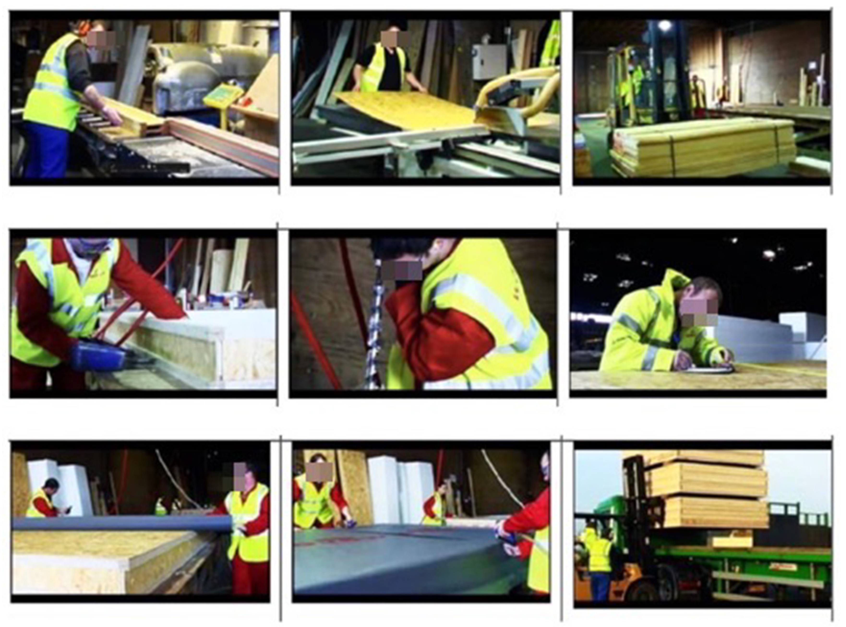
Figure 1 shows images of the assembly process of the WAVE Homes [
9] closed panel timber frame factory that our early closed panel research [
7] was a precursor to. It addressed some of the production issues that we had experienced and represented an improvement in the processes and quality of completed product.
Although the WAVE system was relatively novel in component production and arrangement, the system of assembly on site was largely conventional. However, we reflected that one manufacturing alternative to fixed factory production that has been successfully explored for certain products is the mobile factory [
9,
10]. This concept uses the benefits of industrialised process such as DFMA (Design for Manufacturing and Assembly) and Lean Systems to help increase quality and levels of productivity [
11]. Mobile factories aim to respond to Lean principles by capturing the benefits of industrialised practices without the high fixed costs of a static factory [
12].
There has, consequently, been a realisation that research into mobile manufacture applied to building construction has great potential. For instance, European Union funding supported the Manubuild [
13] programme looking at concepts such as containerised factories. In another example, Sanska UK [
14] have tested the ‘flying factories’ concept [
10].
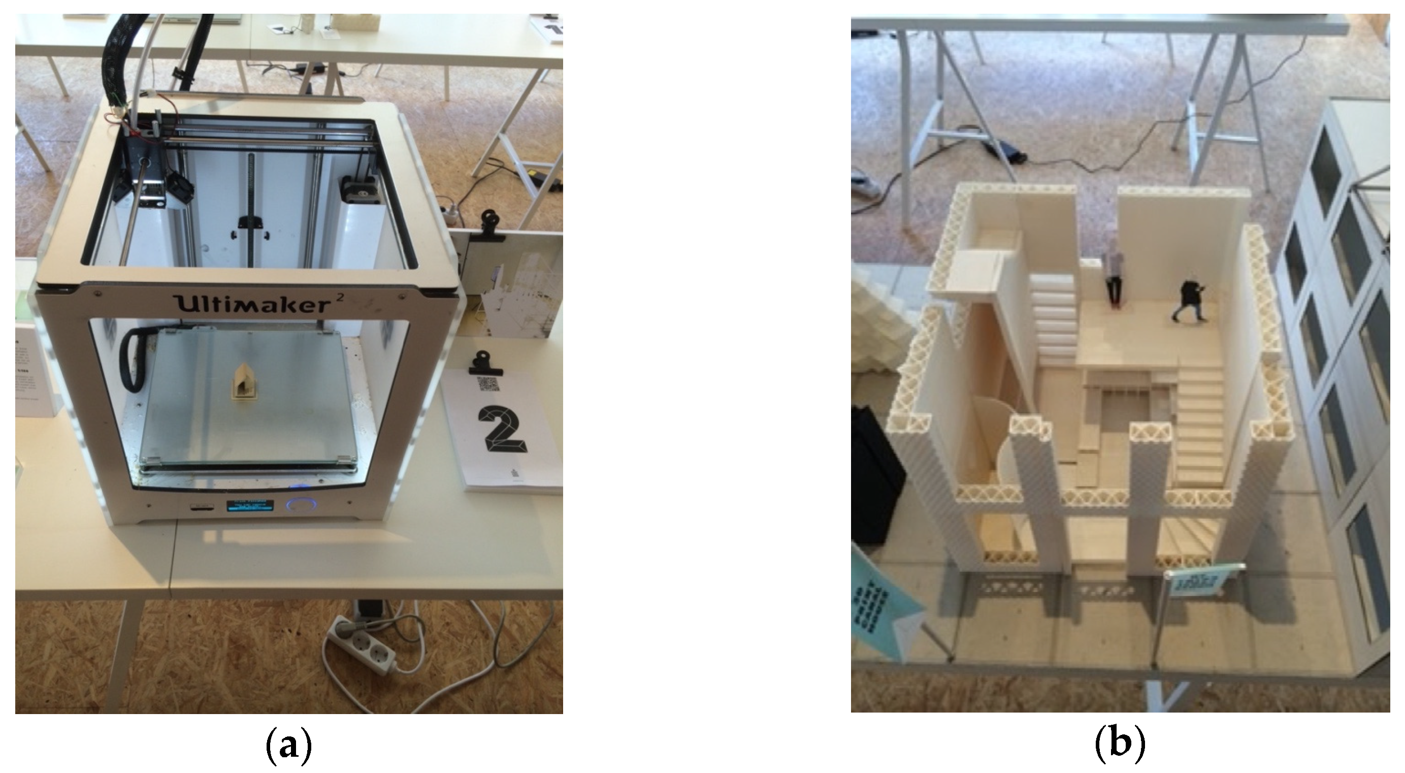
Other systems employing techniques such as 3D printed construction [
15] and containerised CNC [
16] processes are further examples where mobile factory systems have been employed to deliver manufacturing systems more effectively as an on-site activity. Examples of different approaches to mobile manufacturing can be seen in
Figure 2,
Figure 3 and
Figure 4.
In response to such ideas, we began work five years ago on developing a mobile timber frame assembly unit. This paper reports on the development of a Prototype Unit (PU) used to test the concept. Associated work considered which novel skills sets and associated skills training potentials this system could provide. In parallel work, we have also considered how the unit could integrate with other mobile units at a site (space permitting) in order to allow operations at a larger scale and to ensure scalability.
This paper reports on:
Full scale tests then examined the functionality and performance of the prototype unit during the assembly of a prefabricated timber closed panel.
2. Mobile Panel-Making Factory Concept
2.1. Technique Adopted for Developing a Mobile Panel-Making Unit
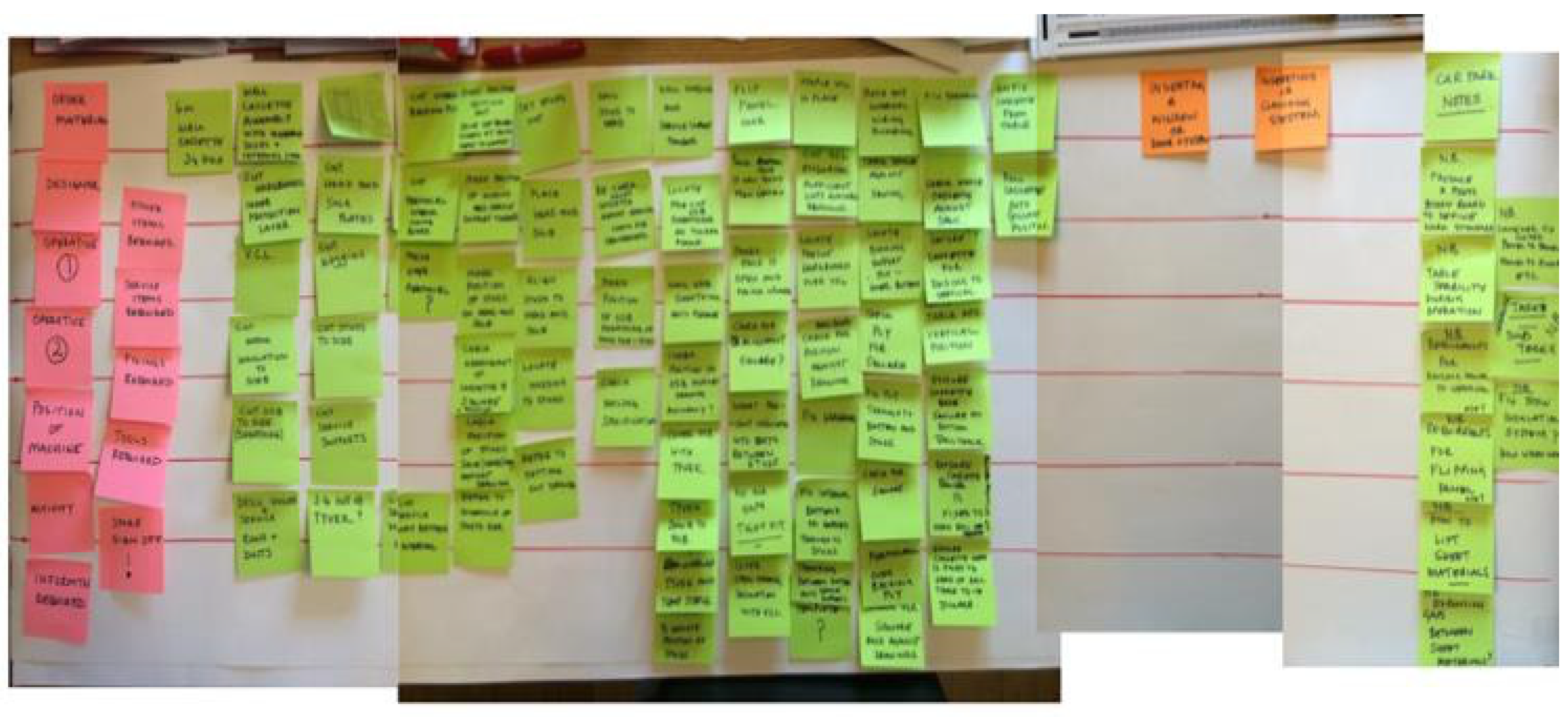
We chose to use the technique of Visual Mapping [
9] to initiate the design process. This is a technique used to visualise the production of new or modified products or workflows. We planned to work with stakeholders from different backgrounds, and visual mapping had the advantage of effectively providing a common language among these stakeholders. This technique can appropriately be part of a Lean approach to achieving efficiency and value [
17]. Many industry sectors have benefitted from the introduction of Lean ideas [
18] into their processes, and several authors have reported on such adoption as a part of the most current timber panel prefabrication process [
19,
20]. Lean thinking dictates that systems and processes must be managed effectively, and that activities must be linked and accurately identified in order to create the necessary order in which to produce specific products. The aim is to facilitate a seamless flow and allow further analysis to enable continued improvement [
11]. In order for this to be achieved, one of the first steps in the development of a system is to construct a Value Stream Map (VSM).
Figure 5 shows the first stage of the Value Stream mapping process that we used to set the framework for the mobile timber panel-making unit.
2.2. Appropriate Performance
The starting place for developing such a system is to fully understand what is required and to understand how the concept will provide value to the target audience [
21]. Essentially, in our case, for the mobile manufacturing concept to provide ‘value’ it must (according to Martinez [
12]) be a system operating affordably and competitively, and have a relevant role in assisting in the processes involved in constructing buildings that meet performance specifications. Timber frame construction in all its forms has become a recognised part of the Modern Methods of achieving sustainable buildings [
14]. Research on associated environmental issues has indicated that prefabrication of timber frame elements is an effective way to deliver these construction elements in terms of both sustainable construction and economic sustainability. Sustainability drivers facing procurers of buildings today require them to consider a comprehensive range of envelope solutions that are ‘smarter, that provide best performance, sustainability, value and aesthetics’ [
22]. Timber frame walls are either stick-built ‘piece by piece’ on site or prefabricated as modular units/cassettes, such as SIPS. The system presented here produces a modular unit. Prefabrication assembly has been shown to achieve tighter tolerances, resulting in better building and environmental performance [
23].
A set of issues responding to the observations above required consideration in order to underpin the development of a prototype that would enable the delivery of the system to produce prefabricated panels through low-impact on-site manufacture. The particular aspects that we considered in the current development, and which we report here, were:
Agility
Mobility in response to viable transport and potential site conditions
Rationalising the operator skillset required
Process and logistics
Cost of establishment
Logistics
Preparation and deployment
Optimising cost in operation.
Notes on each of these aspects are presented below, and the matrix of interconnectedness of these issues is provided in Table 1.
2.2.1. Agility
The ‘uncertainty and change’ that is prevalent in the construction industry, particularly in the current context means that the best technological solutions need to be agile and highly responsive. To be successful, such solutions need to be both low-cost and effective [
24]. This desire for agility is a core idea in the mobile factory proposition described in this paper.
The mobile panel-making unit, or Prototype Unit, is a towable micro-factory housing an autonomous system that can be towed behind a suitable vehicle. Envisaged initially as being located on residential construction sites or in temporary facilities nearby, it permits the assembly of structural wall, roof and floor cassettes remote from any fixed service connection. The envisaged applications included both new buildings and refurbishment. It was envisaged that the cassettes being constructed would be integrated and could incorporate cladding and finishes, insulation, services, integrated renewables, and fenestration and shading devices. Such flexibility maximises capability and applicability.
The operational steps that were envisaged are shown in
Figure 6 and were developed from manufacturing processes rather than more traditional site-based operations or trade demarcations. There were deliberately no trade skills delineated in the steps of the process. The process was driven by a need to create the consistent flow noted as essential by Bicheno [
17] in achieving a Lean operation.
The diagrammatic sketches seen in
Figure 7,
Figure 8,
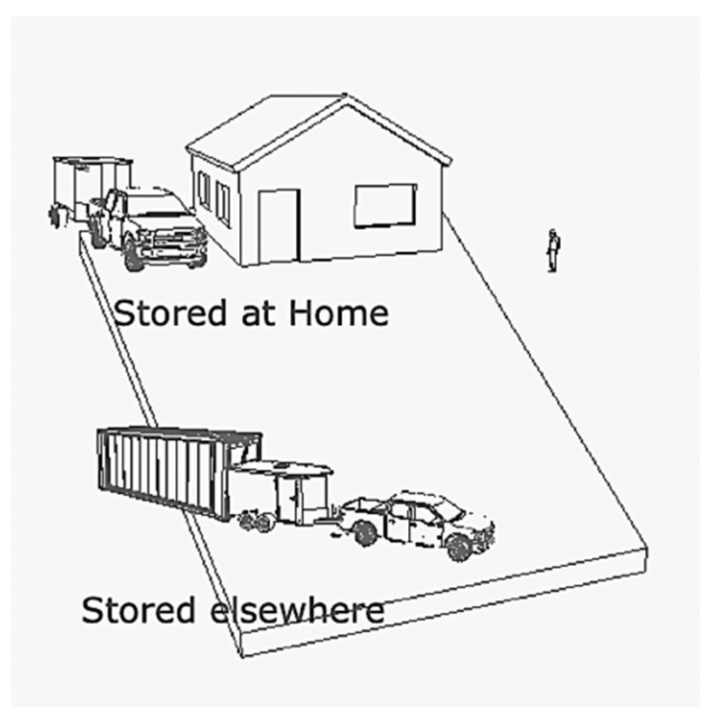
Figure 9 and
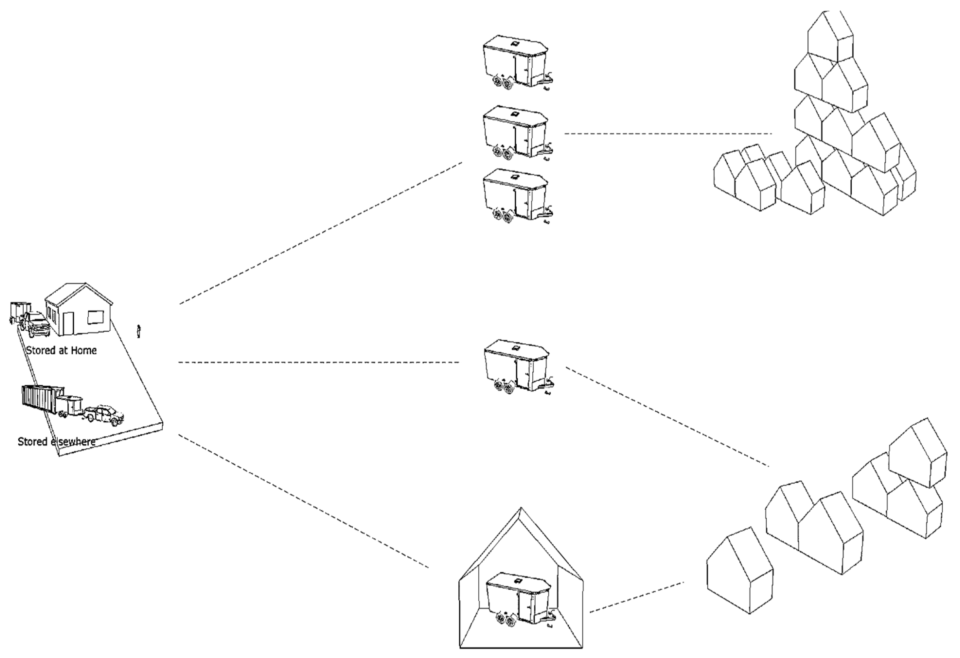
Figure 10 below provide an illustrated view of the basic concept for the mobile panel making unit, showing the PU being taken from (typically) a home base to a site, subsequently deployed, and used to assemble envelope components onsite using either manual or small crane assembly, before returning to base.
2.2.2. Skills and Retention
It is important to consider the concept of mobile manufacturing as having the potential to attract new people into the industry through a more process-based or industrial approach to building, rather than the traditional labour-intensive approach. However, the process should not at the same time displace craft-based and skilled people from the current workforce, especially when issues of workforce retention are so problematic in the UK industry. The process envisaged here should have the potential to retain existing skilled members of the trained workforce by reducing the physical demands [
25] often experienced with more traditional methods of working on-site, allowing them to focus on their specialist activities. For example, introducing smart lifting and cutting equipment can help to complete more process tasks, and therefore offer a less laborious process. Introducing a process-based approach rather than a trade demarcation-driven process is intended to offer access to the industry to a broader set of individuals through multi-skill and up-skill approaches. Achieving this was driven by the knowledge that achieving such an outcome can contribute to leveraging the ‘potential for creativity and skill that already exists in the industry’ [
26].
2.2.3. Process
Task Design was used to devise the process to be adopted. This is a practice ‘widely applied by global companies’ [
25]. It is employed partly to overcome a mismatch or shortage in skills while maintaining consistent product quality and required levels of productivity. To achieve this, the demands of the tasks are set at or below the capacities and skill base available [
27]. This can be achieved partly through adoption of devices such as jigs, which are visual controls to aid in setting out guides and templates to help gain consistency of product. Task design can enable a staircasing of skills from initial basic learning through to eventually carrying out complex tasks via an incremental scaffolding process. This encourages a ‘repertoire of skills’ to develop among participants. Importantly, this has been shown to result in increased job satisfaction and an increase in personal confidence [
25].
2.2.4. Cost Considerations
The business establishment costs of mobile facilities are considerably less than a fixed factory. This is one of the particular advantages. To remain competitive and relevant economically and to outweigh the benefits of traditionally capital-intensive fixed factory production, the mobile micro-factory must have certain qualities. These were established as the ability “to bypass the complex logistics, expense and standardisation of fixed factory mass production, in the way the company deploys on-site mobile production facilities. These compact mobile units must contain all the equipment needed to manufacture the components for each house, eliminating the need to transport large-scale prefabricated structures – and the associated carbon emissions” [
16]. For a mobile panel-making system to compete and be commercially sustainable it must be able to cope with the financial peaks and troughs in the housing market and enter the sector at an appropriate and affordable level both in terms of acquisition and operation.
2.2.5. Logistics
In addition to the prototype specifications mentioned above, it was envisaged that the footprint of the unit while being transported or stored should be no larger than 6 m × 2 m. This is a tight footprint based on maximising flexibility, and would make the unit suitable for domestic driveway parking or being located in a facility such as a 20 ft ISO shipping container. Furthermore, the maneuverability between locations was designed to be achieved by only one individual using the power of the tow vehicle. Keeping overheads low by employing multi-functions in this way is a key aspect of the mobile factory concept [
10,
24]. The dimensions of the platform noted above facilitate transportation. In addition, the unit should have the capability to be extended during set-up into a horizontal table capable of assembling large format floor, wall or roof cassettes as prefabricated elements.
With the specifications described above achieved, the combination of towability, robust construction and compact volume would enable local, national and international transportability in both tight urban settings and difficult rural locations. Operating either as a single entity or having the potential to ‘dock’ (see
Figure 10) together as a family of generic mobile units offers different types of production-flow to meet a range of development scales and project requirements [
9].
2.2.6. Preparation and Deployment
For the mobile system to operate efficiently and competitively, an initial assessment of the place of operation, or site, requires that an effective and safe flow of processes is achieved by the correct positioning of the system during set-up taking individual site constraints into accounts [
9]. Fast deployment [
26] from a tow unit into a weather protected temporary fixed assembly platform should be possible by only two operators. This should also be the case for the disassembly process. Positioning of the unit within the process flow on a site should accommodate both acceptance of raw materials into the site and the storage of made components into stillaging prior to erection of any subsequent building, as described in detail in
Section 4, below.
2.2.7. Processes
To test the prototype, the task set was the assembly of a closed structural wall panel (cassette). It was intended that bulk (raw) materials would be processed into stud and sheet components via dedicated cutting stations. Following the cutting process, transfer carriages within the system would aid the movement of cut material onto the assembly bench where integral stops and guides would position the component materials prior to fixing as a composite unit. Quality assurance steps were assigned to each task. A visual system [
28] was used to define tasks and attain a consistent standard [
29]. Once open frames (the skeleton) had been initially assembled, a gantry lift was designed to flip over the open frame onto the alternate face, allowing panels to be finished and contained as a complete closed panel. This process facilitates completed wall, floor or roof components for mechanical transfer from the assembly bench to storage stillages prior to being lifted into place in the building under construction.
2.2.8. Cost Base
Low cost in component manufacture, unit operation and storage was a key conceptual aim of the proposal. The need for high levels of fitness or physical strength along with specialised skills and knowledge to operate the unit were minimised. The concept envisaged an entry level unit to prove the concept; this core unit would then become the growth hub for a connected network of differently-capable mobile units on the same site. The proposition required that the tasks involved in the operation of the micro-factory require only two trained operatives, adding to the low-cost, developable and agile nature of the concept.
3. Taking Concept into Practice
An essential part of this research was to validate the concept through physical testing. Validation is often undertaken through simulations performed on models in various forms [
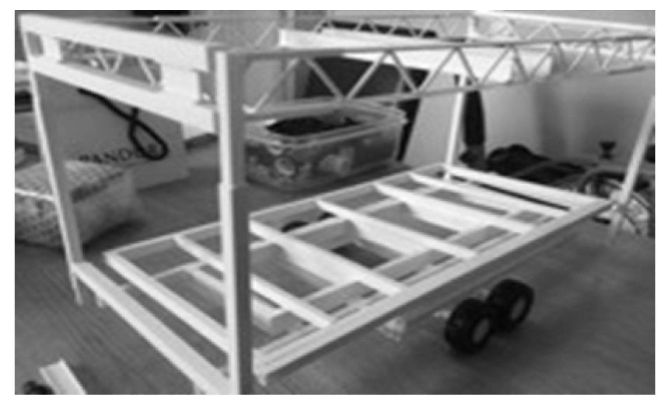
30]. In our case, the micro-factory prototype unit was modelled digitally first, then a scale model was made, and simple operational functions and dimensions were consequently established. However, the functionality of the working unit could only be fully evaluated and modified through developing and refining a full-scale prototype unit capable of the assembly of a series of full-size structural closed panels. The prototype unit was typical of a first prototype and not of final production quality, as its function was to test the core specifications. The prototype was therefore designed and assembled utilizing a pragmatic philosophy. As far as possible, the components used were off the shelf and readily available. A small physical model helped organise the ideas for the prototype (see
Figure 11).
Following the drawing, modelling and scale model examination of concept, we needed to fully understand the issues presented by construction at full scale of the structural components that panelized timber framing requires.
The 3D models that were created to visualize the process were informed by:
The visual mapping process described above
Small physical model construction
Response to specifications
The relative location of the main components used in the prototype are illustrated in the images from the 3D modelling in
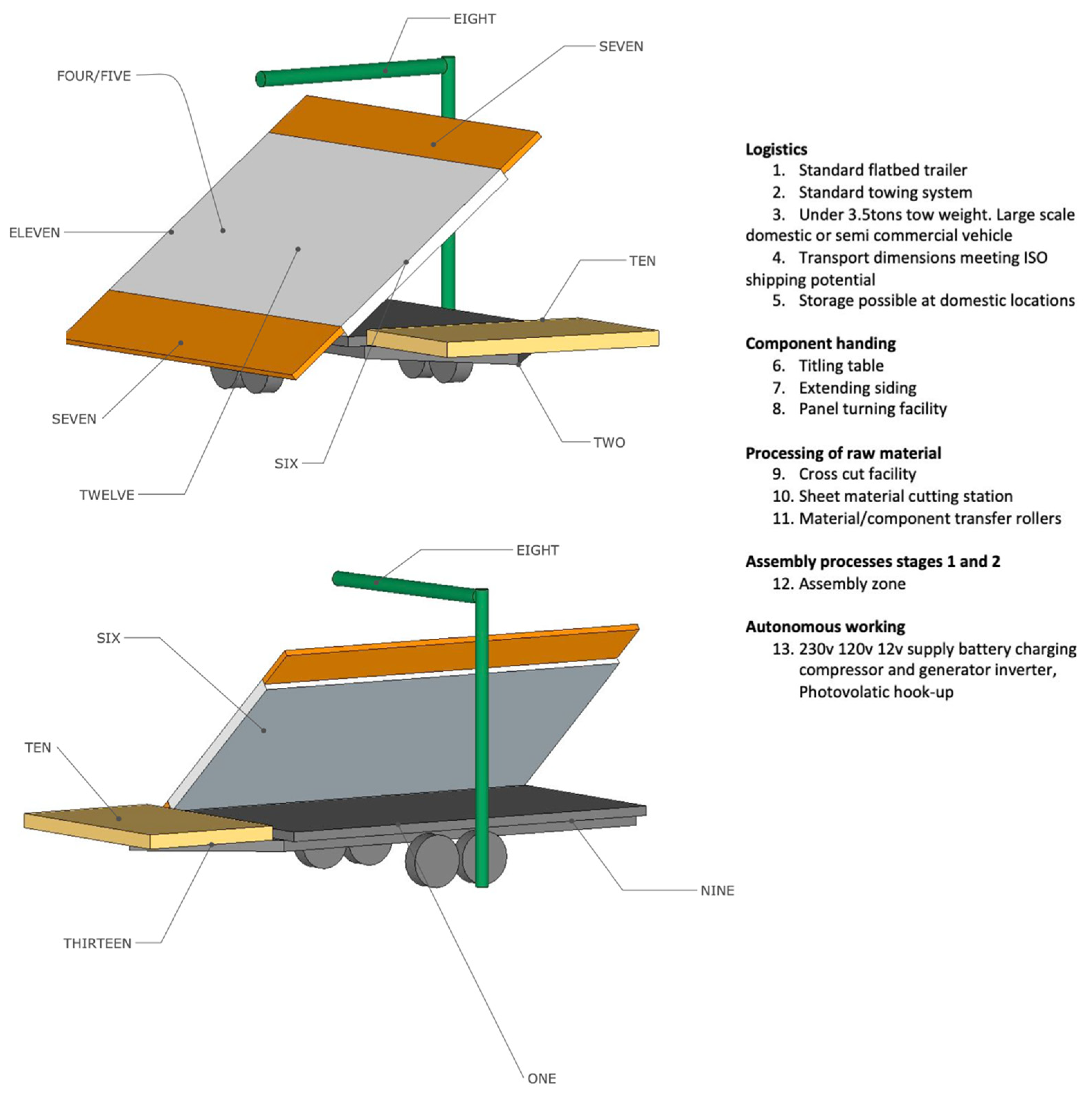
Figure 12. The key components highlighted are those that were critical to the performance requirements of the prototype as outlined earlier in the concept development criteria.
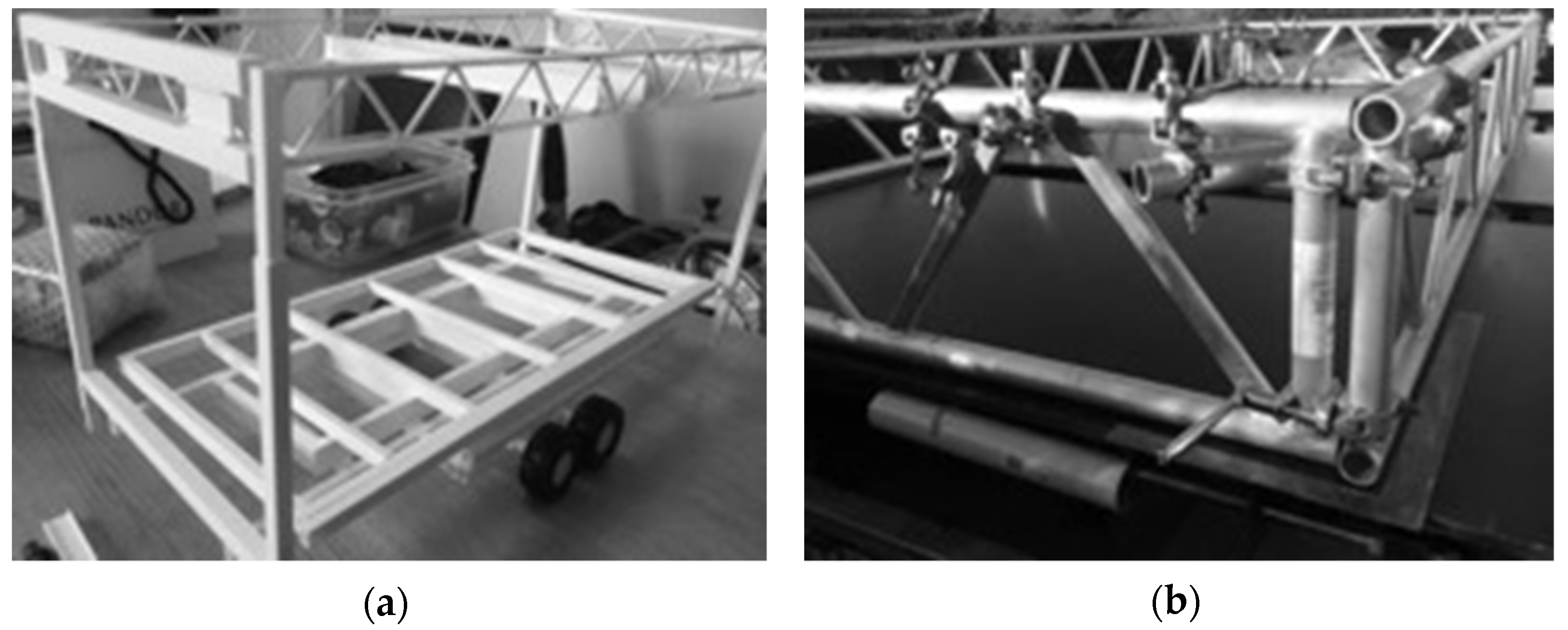
The first full-scale version was then constructed in line with the 3D model shown in
Figure 11. The photographs in
Figure 13 and
Figure 14 show the fabricated physical components conceived in the prototype development process above.
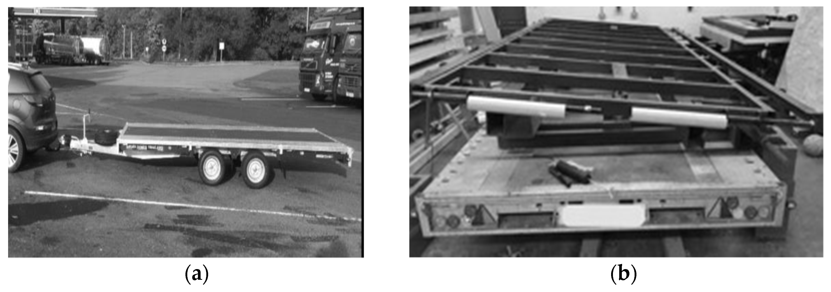
Figure 13 shows the base component, the flatbed trailer (a), and the tilting table (b).
3.1. Logistics: Achieving Mobility
A fundamental base from which the proposed deployable micro-factory was developed was a basic flat-bed trailer (
Figure 13a). The physical size was derived from the on-site footprint specification mentioned earlier. Other specifications, such as load capacity, were derived from estimations of production component weights.
The trailer needed to be a twin-axle multipurpose unit. The maximum external dimensions of the trailer were conditioned by the internal measurements of an ISO shiping container, with additional space to allow room for loading and unloading (see
Figure 14).
The proposed system allows the unit to be towed to construction sites or temporary locations, and provides a self-contained assembly platform. Storage at a domestic-scale location was also a consideration.
3.2. Logistics: Component Handling
Bolted to the top of the trailer bed via a transverse sub-chassis is a full-length (4 m) tilting table (
Figure 15). The table is hinged to the sub-chassis on one side along one of the longer sides of the trailer. The table can be tilted 85 degrees, from a horizontal position to a near-vertical alignment. The tilting arrangement allows sub-assemblies that have been constructed (open or closed panels) to be transferred to a ‘toast-rack’ stillage from the table in either a horizontal or a vertical orientation (
Figure 15) for storage prior to erection or further finishing or other manouevering tasks.
Rollers located at each end of the table (
Figure 16) facilitate horizontal transfer and loading of sheet material onto the table. Two motorised hydraulic multi-stage rams situated between sub chassis and the tilting table can facilitate tilting a range of differently sized and eccentrically loaded sub-assembly stillage. Running parallel along each of the longest sides of the tilting tabletop, extending rams increase the overall width of the tabletop to beyond that of the standard trailer width, accommodating a variety of different sizes of components that would otherwise be beyond the standard trailer dimensions. Structural panels with dimensions up to 4m long by 3 m wide and 0.5 m deep can be assembled and transferred using the extending and articulating table. However, the base micro-factory is sized to facilitate transportation using a standard ISO shipping container, allowing international transportation.
3.3. Assembly Processes: First Stage
Sheet and linear (stick) materials are loaded onto the tabletop via rollers at each end of the table. Stick material (e.g., the sole/base plate) is located in place at a ‘setting-out’ hard stop running along the edge of tilting table. A right-angle adjustable edge aligns the first/last stud position at each end of the tilting table. The head plate and studs are located accordingly. Manual air pressure nail guns are used to fix sole (base) and head plates to studs. Sheet material is located and nailed, completing the face of the open panel. Subsequent layers to be added to this face can then be applied according to specification.
3.4. Assembly Processes: Second Stage
Insulation, membranes, service items and other components can be fixed to the structure here before any further layers are applied to close the panel. Transfer of assembled panels to storage stillages is completed either by manouevering the whole tilting table through a near vertical position and siding the panel onto the stillage, or by transferring the panel horizontally via the table rollers located on the tabletop. Horizontal stillages or mobile magazines hold the completed panel until required.
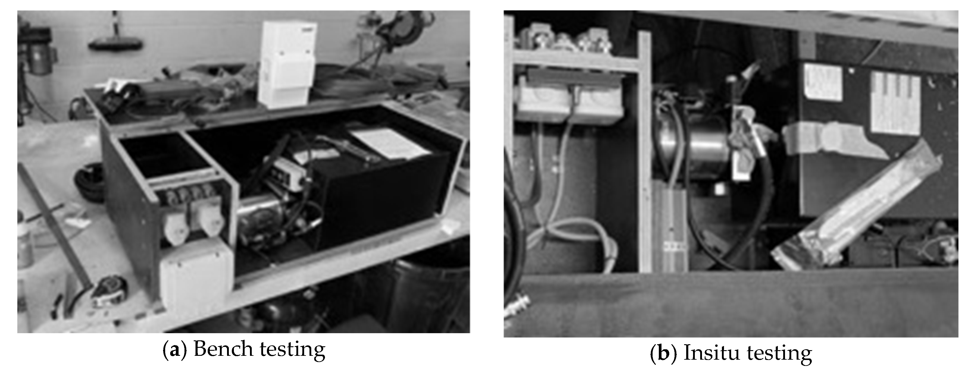
3.5. Autonomous Functioning and Power Hookup
The autonomous power system is available for charging, lighting, tool/plant operation and communications systems. The system employed can be seen in
Figure 17.
3.6. Deployable Canopy and Support Structure
Weather protection designed to cover all operations is provided by means of a Flexible Extending Canopy (
Figure 18). It employs a combination of a rigid main roof structure and expandable flexible membranes attached to the main roof, allowing a degree of flexibility in the amounts of protected floor area.
The main roof is constructed using a perimeter of trussed Laher edge beams (
Figure 18) braced at each corner. Attached vertically to each of the four corners are horizontally-folding legs that, when opened out, double the footprint of the roof area. Four telescopic drop legs, one fixed to the ends of each folding leg, descend to support the whole canopy in the high-level operational state. Lightweight curved ply rafters extend equi-spaced between the main two parallel Laher edge beams and provide support for a fully sheathed curved roof deck. The covered area is sufficient to provide weather protection to the cutting, sorting, assembly and transfer operations of the micro-factory.
4. Evaluation of the Functionality of the PU
In establishing the proof of concept, the evaluation undertaken in this paper focuses on three areas of prototype unit operation.
Logistics, relating to the preparation, transportation and site set-up of the mobile factory
On-site assembly, enabling the tasks and processes involved in the assembly of structural closed panels
Outputs, that is, the quality of the assembled panels as assessed against recognised panel-making norms.
In assembling closed panels, the full spectrum of mechanical facilities and processes provided by the Prototype Unit were employed. This testing helped to establish direction for further development of the system and associated research. The findings in this paper were derived from the test operation of the PU by operators from a local carpentry company. They undertook the operation of the unit following a short period of familiarisation. These initial tests have formed part of a series of ongoing observations. During physical activities in the evaluation process, the activities were observed and recorded.
As part of the prototyping development work, two aspects were considered particularly critical to establishing initial criteria for the evaluation process:
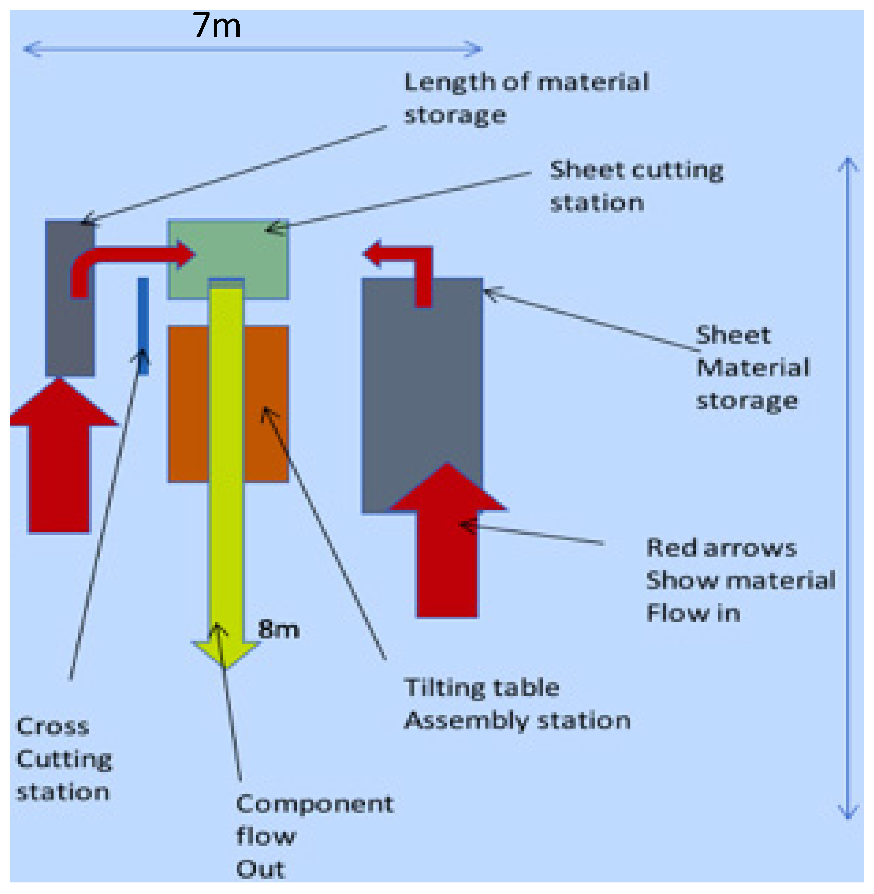
Several iterations of the process were advanced concerning raw material flow into the unit and the removal of assembled components from it. Site access, storage, and space to undertake tasks were estimated. The process shown below (
Figure 19) was selected on the basis that it had clearly differentiated points of access and exit, similar in most respects to ideal small building sites and temporary warehouse facilities.
From an assessment of commercially available closed panels, a panel fabrication process was designed that would meet good sustainable construction standards in relation to issues such as thermal performance and appropriate material use. This required that tasks be carried out on both faces of the panel. The manipulation and other processing tasks consequently required in the assembly had already been modelled as described earlier.
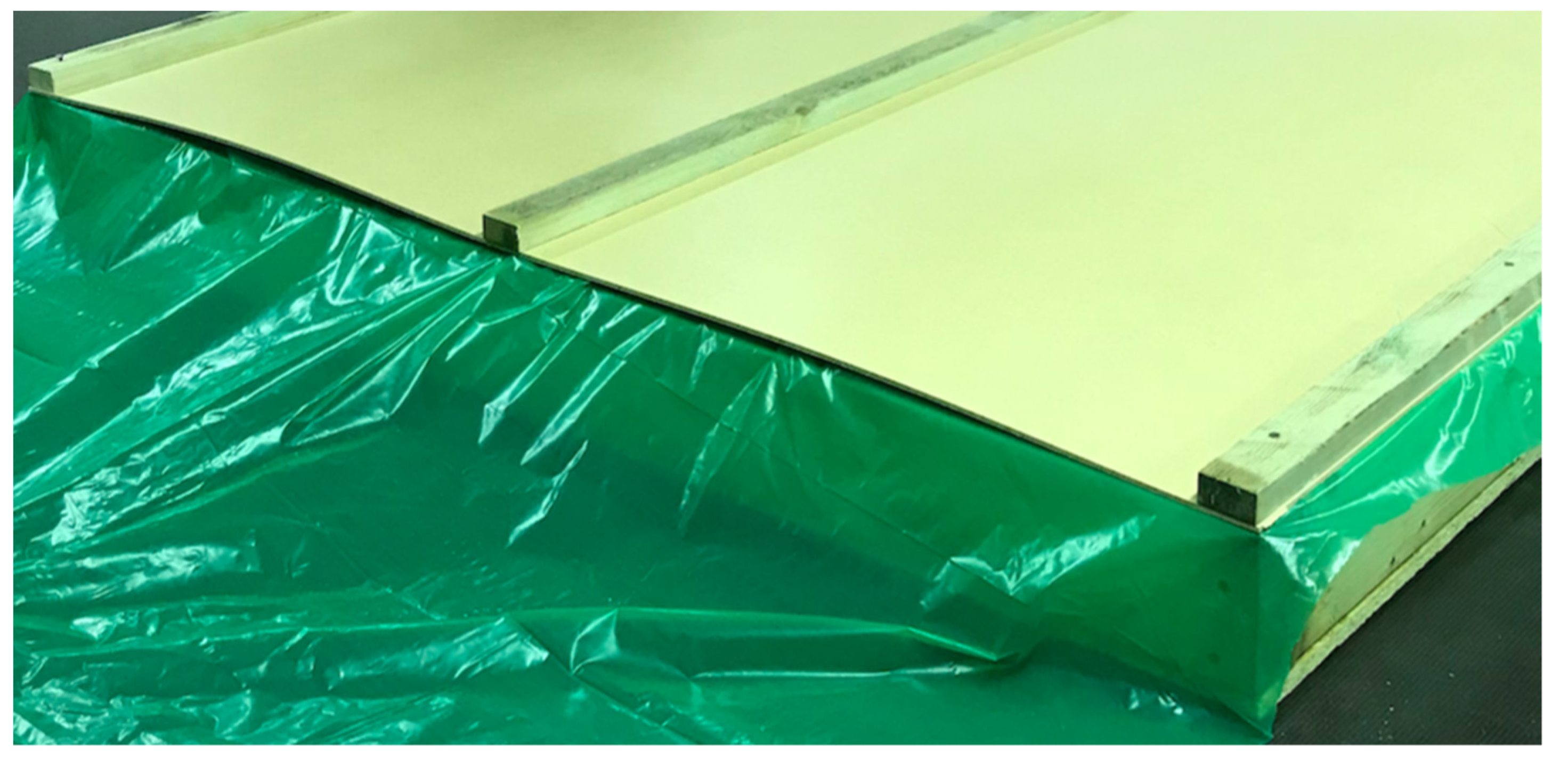
A typical closed panel produced by the PU is shown in
Figure 20. Construction was broadly in line with the UK Timber Frame Construction Manual [
31], and tolerances were specified. Operators were asked to consecutively assemble a number of identical panels with the same specifications.
5. Observations
5.1. Logistics
The concept assumed two operatives using one vehicle. Most operations were successfully completed, although the weight of the trailer was challenging in terms of the physical strength required to manoeuver it, and in all cases the tow vehicle had to align with the unit to avoid the need for manual location.
Setup
Providing a secure and safe working platform is an essential aspect of the operation of the Prototype Unit; however, from the start, setting up the unit to begin work raised a number of challenges. Even a small reduction in the size of the defined operational plan area made establishing dimensions for the unit even more essential if the processes were to continue safely. During the prototype development work, resolving stability issues during the course of raising the canopy had not been fully resolved, and this was again highlighted as the volunteer fabricators began to erect the frame of the canopy. The canopy deployment was stopped early on health and safety grounds, and the canopy was removed from the system for testing and refinement. Resolving the weather canopy design and operation will be a further iteration of the system in the future. While visibly frustrated by these early issues, the volunteers made positive suggestions and were encouraging about plans to move forward with further refinements.
5.2. On-Site Assembly
5.2.1. Material Flow
Material flow into the process requires a delivery vehicle to off-load materials into allocated storage space either side of the PU. The impact of compressing the plan shortened the space available for circulation. This was significant enough to restrict the ability to carry materials safely, and volunteers became noticeably stressed moving materials in this situation.
5.2.2. Raw Material Processing
The process map assumed that materials and assembled components were part of the enabling functions supporting PU operation, not part of the development itself. With allocated space for pallets compromised, the task of maneuvering materials was regarded as a separate operation. Temporary carts made from pallets with added castors to move materials accurately to the PU performed reasonably well in terms of delivery of the correct materials to a station; however, the process required volunteers to bend and lift materials excessively compared to the project goals. This aspect requires further attention to reach acceptability.
The sheet-cutting station (
Figure 12, component ten) was set too high to provide an optimum position to complete tasks comfortably. Marking cutlines on the sheet material was difficult due to surface roughness, and we noted that setting location stops on the saw could be improved as well. An ergonomic observation and analysis revealed some manual tasks beyond arms-length. Aligning the track saw accuracy improved as the quantity of cut sheeting increased. The track saw performed as intended on the station (
Figure 11, component nine).
No space had been allocated in the plan for temporary tool storage. This was an issue observed for tooling generally. Floor and table surfaces became cluttered with tools and required constant reorganising. Addition of a tool rack system is another key future development. After processing, materials were passed over rollers onto the assembly table (see
Figure 12, component 11). In some cases, the raw and processed materials became confused despite the process flow design. Again, this issue requires a pragmatic solution.
5.2.3. Setting out and Assembling Components
Setting out processed material (studs and sheets) against the assembly table’s predefined stops (
Figure 12, component seven) worked as intended. The surface of the assembly table was sometimes too high, and required operatives to over-reach to set studs between head and sole/base plates. Hop-ups (step boxes) were required to aid access.
Tooling, particularly nail guns, were heavier than was ideal for prolonged periods of manual operation, and cabling and hoses occasionally fouled against various protrusions. The need to share tools slowed the production process where completing tasks would have otherwise been possible, although this was recognised by the volunteers as a result of prototyping rather than a deficiency in the concept.
5.2.4. Flipping the Panels
A gantry (
Figure 12, component eight) on the PU enabled panels to be flipped from one face to the other successfully. The panel ascended to the top of the jib without significant incident with only a small amount of flexing in the panel observed; however, on lowering the column supporting the jib began to show a response to flexing in the panels. As the speed of lowering lessened, the amount of flexing did as well, and a satisfactory optimum lowering speed was identified.
It was noted that score marks occurred on the table top after manually repositioning the flipped panel into the exact position on the table top after flipping.
5.2.5. Tilting the Panels
Due to the considerable loads needed to manipulate the panel during these live tests, and through the experience gained during prototyping, particular care was given to the operation of the hydraulic system. Flipping and tilting the panel in the assembly process was considered the most complex manipulation of the panels in the assembly process. With the table (
Figure 12, component six) in the horizontal position, the sole/base of the panel is located against stopper/rollers (
Figure 16a). To move the panel into the vertical position (85 degrees) took the system approximately one minute before coming to rest. The volunteers then pushed the panel on the rollers into a temporary ‘toast rack’ structure. The table returned to horizontal under the self-weight of the table. No significant issues were recorded in the panel flipping process.
5.3. Quality of Closed Panels
The test panels assembled by volunteers achieved the quality and met the specification selected to meet the UK’s Timber Research and Development Association (TRADA) standards [
31]. Their performance compared well with the specific criteria for tolerances for the panels to be used as part of the structure of an external wall of a building. The volunteers checked the quality of the panels themselves while being observed, as part of a self-review process. Each panel was then checked separately by the observer against the specifications.
5.4. Summary Observations
Closed panels suitable for house construction were assembled repeatedly. These panels consistently met the required specifications and quality. Certain aspects of development proved more challenging than expected. It was found that making the peripheral enabling tasks function appropriately was a much greater challenge than had been anticipated. The operation of the Prototype Unit in the processes of flipping and tilting during assembly proved relatively successful and straightforward. This is not surprising, as this was where the focus of the prototyping had concentrated the most design development and resources.
The value of scheduling material supply correctly to workstations, sharing tools in an organized tooling system, and ensuring consistent storage were identified as main issues that resulted in some inefficiency in the lean, sustainable construction approach that was the underlying aim [
32].These are key areas to be addressed in the future. However, in terms of testing the prototype these issues did not prevent large-format closed panels from being constructed and manipulated sufficiently to allow tasks to be completed on all edges and both faces. These observations demonstrate that prototyping is very much about a phased approach, as well as the importance that full-scale testing has in the development of systems.
There is little doubt that the existing skill sets of the volunteers, developed after years working in the carpentry trade, helped mitigate the impact of these issues, as did their physical strength. The observations provided a useful indicator as to where further research and development work should focus in order to achieve operation by users with a less advanced skill-set and level of physical capability.
We should at this point note the creativity and experience of the carpenters who took part in first-phase testing. This helped significantly in overcoming the hurdles experienced in the prototype testing. The work of Young et. al. [
26] further supports the value of input by skilled workers in product development, and suggests that this is often an untapped resource, particularly when the focus is on developing processes that are task-focused or aiming to de-skill/re-skill.
Table 1 provides a summary overview of the outputs from the operation and evaluation of the prototype as a record of the proof-of-concept stage in the continued development of the mobile panel-making factory proposition.
6. Conclusions
The research and development of the Prototype Unit used to deliver the assembly of closed prefabricated panels in a mobile micro-factory is unique as far as we are aware. The work in this paper describes the proof of concept and successful delivery of a set of outputs prescribed in the performance specifications and proposition. The underlying research aim related to prefabrication as a means of achieving a more flexible, affordable, agile, and therefore appropriately sustainable construction system.
The completed work provides considerable optimism in seeking to provide a springboard for further development of this low-cost mobile factory system. Its particular application as envisaged was in the assembly of panelised houses, although clearly other applications in panelised (cassette) forms of timber construction are possible. Not only did the prototype unit meet nearly all of the performance criteria to a good standard, the testing of the PU showed that it is possible for a small team of one or two to assemble closed panels in a temporary and potentially constricted location, and achieved all this with a minimal footprint. It is important to note that in the development of the unit, the researchers were mindful that compromises in safety should not be made in order to reach the target levels of panel quality and production efficiency.
Careful organisation of materials and components with easy manoeuverability prior to assembly is essential to maintaining flow in the production of the panelised components in a way that meshes well with the overall contract programme, and we noted that these peripheral support activities do require further attention.
In comparison with other mobile factory systems, the prototype unit primarily differs in approach in three distinct ways. First, many existing on-site factories are deployed using ready-made enclosures, usually shipping containers, that require dedicated vehicles sufficiently adept to transport and lift the kit into place. For this to happen, sites and locations must be accessible and have good terrain conditions as well as sufficient space. In contrast, the inherent agility of our system is achieved by having a minimal, economically sustainable base unit of domestic tow vehicle and trailer. The PU requires less infrastructure and minimal site space to set up the dedicated factory operation, even when access is limited. Second, other mobile factory systems often operate inside existing facilities that can be hired, while ours is autonomous. Finally, mobile factory systems generally focus on systemizing existing site labour practices under cover, rather than re-thinking the processes and the associated tooling in the way that we have.
Achieving simple low-cost mobility, operation, and storage by the target user is fundamental to the concept of a mobile factory. The work reported here establishes the achievability of the concept. Additionally, our work indicates that the simple idea of a checklist for operators of the Prototype Unit would increase set-up efficiency, and would help with initial determination of whether contracts were suitable for the mobile factory approach. Overall, the observations show that further research should be focused on the areas of:
Ergonomics, to enable a process that is as efficient and operator-friendly as possible
Organisation of tooling
Further refinement of the all-weather canopy structure.
Further work will additionally focus on the integration of operators with different skill sets, particularly those with very limited experience. The micro-factory technology that has been developed has the potential to address the workforce shortages mentioned earlier through the development of processes that are economically viable, flexible, less physically demanding, and more rewarding.
Author Contributions
Conceptualization, S.G. and A.B.; methodology, S.G. and A.B.; validation, S.G. and A.B.; investigation, S.G.; resources, S.G.; data curation, S.G. and A.B.; writing—review and editing S.G. and A.B.; visualization, S.G.; supervision, A.B.; project administration S.G. and A.B.; CGE funding acquisition, A.B. All authors have read and agreed to the published version of the manuscript.
Funding
Initial funding was provided by the CGE (Centre for Global Eco-Innovation), administered by the Universities of Lancaster and Liverpool. Additional commercial support in the initial proposal development was provided by John McCall Architects in partnership with CGE and the work after 2015 was self-funded. See:
https://www.liverpool.ac.uk/environmental-sciences/the-innovatory/centre-for-global-eco-innovation/phd-projects/ (accessed on 29 September 2021). The CGE project won a RCUK Impact Award for Outstanding Knowledge Exchange and Commercialisation and the Green Gown Award for Eco-Innovative Research.
Institutional Review Board Statement
Not applicable.
Informed Consent Statement
Not applicable.
Data Availability Statement
Figures not provided by the authors are available publicly.
Acknowledgments
We are extremely grateful to the volunteers who took part in the testing of the Prototype Unit by prefabricating panels to a given specification.
Conflicts of Interest
The authors declare no conflict of interest.
Intellectual Property
IP for the Prototype described in this paper resides with the authors.
Abbreviations
PU—Prototype Unit; TRADA—Timber Research and Development Association (UK).
References
- Farmer, M. The Farmer Review of the UK Construction Labour Model: Modernise or Die: Time to Decide the Industry’s Future; Construction Leadership Council (CLC): London, UK, 2016. [Google Scholar]
- Jackson, G. How a Lack of Skilled Building Workers Is Stunting UK Growth. Financial Times London, 16 August 2018. [Google Scholar]
- Anon. Reversing the Decline of Small Housebuilders: Reinvigorating Entrepreneurialism and Building More House; Home Builders Federation (HBF): London, UK, 2017. [Google Scholar]
- United Nations General Assembly, Resolution Adopted by the General Assembly on 25th September 2015. Transforming Our World: Agenda for Sustainable Development. Available online: https://www.un.org/ga/search/view_doc.asp?symbol=A/RES/70/1&Lang=E (accessed on 29 September 2021).
- Glesekam, J.; Tingley, D.D.; Cotton, I. Aligning carbon targets for construction with (inter)national climate change mitigation commitments. Energy Build. 2018, 165, 106–117. [Google Scholar] [CrossRef]
- Killip, G. A Reform Agenda for UK Construction Education and Practice. Build. Cities 2020, 1, 525–537. [Google Scholar] [CrossRef]
- Gee, S. Prefabricated ‘Green’ Housing at Millenium Mews. Master’s Thesis, University of Liverpool, Liverpool, UK, 2004. [Google Scholar]
- Oesterreich, T.D.; Teuteberg, F. Understanding the Implication of Digitisation and Automaton in the Contectnof INDUSTRY 4.0: A Triangulation Approach and Elements of a Research Agenda for the Construction industry. Comput. Ind. 2016, 83, 121–139. [Google Scholar] [CrossRef]
- Gee, S. The Development of an Innovative, Agile On-site Process to Manufacture Sustainable Building Components. Ph.D. Thesis, University of Liverpool, Liverpool, UK, 2019. [Google Scholar]
- Haukka, S.; Lindqvist, M. Modern Flying Factories in the Construction Industry. Master of Science in Engineering Technology Architecture, s.l. Master’s Thesis, Lulea University of Technology, Lulea, Sweden, 2015. [Google Scholar]
- Womack, J.P.; Jones, D.T. Lean Thinking: Banish Waste and Create Wealth in your Corporation; Simon & Schuster UK Ltd.: London, UK, 2003; p. 37. [Google Scholar]
- Martinez, S.; Jardon, A.; Victores, J.G.; Balaguer, C. Flexible field factory for construction industry. Assem. Autom. 2013, 33, 175–183. [Google Scholar] [CrossRef] [Green Version]
- Bock, T. The Integrated Project Manubuild of the EU; 2006; ISARC2006. Available online: http://www.iaarc.org/publications/proceedings_of_the_23rd_isarc/the_integrated_project_manubuild_of_the_eu.html (accessed on 29 September 2021).
- Ofori-Kuragu, J.K.; Osei-Kyei, R. Mainstreaming pre-manufactured offsite processes in construction—Are we nearly there? Emerald Insight Offsite Processes Constr. 2021, 21, 743. [Google Scholar] [CrossRef]
- Weinstein, D.; Nawara, P. Determining the applicability of 3D concrete construction (Contour Crafting) of low income houses in select countries. Cornell Real Estate Rev. 2015, 13, 94–111. [Google Scholar]
- Bell, B.; Simpkin, S. Domesticating Parametric Design; Wiley & Sons Ltd.: Hoboken, NJ, USA, 2013; Available online: https://onlinelibrary.wiley.com/doi/abs/10.1002/ad.1560 (accessed on 29 September 2021).
- Bicheno, J. The New Lean Toolbox-Towards Fast, Flexible Flow; PICSIE Books: Buckingham, UK, 2004. [Google Scholar]
- Bhasin, S. Performance of lean in large organisations. J. Manuf. Syst. 2012, 31, 349–357. [Google Scholar] [CrossRef]
- Orlowski, K. Automated manufacturing for timber-based panelised wall systems. Autom. Constr. 2020, 109, 102988. [Google Scholar] [CrossRef]
- Duncheva, T.; Bradley, F.F. A Comparison between Volumetric Timber Manufacturing Strategies in the UK and mainland Europe. 2016. Available online: https://journalofindustrializedconstruction.com/index.php/mocs/article/view/2 (accessed on 29 September 2021).
- Rother, M.; Shook, J. Learing to See: Value-Stream Mapping to Create Value and Eliminate Muda, Version 1.3; The Lean Enterprise Institute: Boston, MA, USA, 2003. [Google Scholar]
- Lusty, G. Wall and Window Systems: When Components Are Integrated the Benefits Can Be Huge. EDC Magazine, 1 November 2012; 56–58. [Google Scholar]
- Lovell, J. Building Envelopes: An Integrated Strategy, Architecture Briefs; Princeton Architectural Press: Princeton, NJ, USA, 2010. [Google Scholar]
- Jackson, M.; Zaman, A. Factory-In-A-Box—Mobile Production Capacity on Demand. Intern. J. Mod. Eng. 2007, 8, 12–26. [Google Scholar]
- Fox, S. Moveable Facories: How to enable sustainable widespread manufacturing skills and infrastructure. Technol. Soc. 2015, 42, 49–60. [Google Scholar] [CrossRef]
- Young, B.; Harty, C.; Lu, S.L.; Davies, R. Developing Temporary Manufacturing Facilities for Residential Building: A Case of Modern Flying Factory; 2015. Available online: https://www.arcom.ac.uk/-docs/proceedings/2742314aca443c55bf0a5bc8bc3c7fdf.pdf (accessed on 29 September 2021).
- Ayoub, M.M.; Dempsey, P.G. The psychological approach to manual materials, handling task design. Ergonomincs 1999, 99, 42–173. [Google Scholar]
- Shou, W.; Wang, J.; Wu, P.; Wang, X.; Chong, H.-Y. A cross-sector review on the use of value stream mapping. Int. J. Prod. Res. 2017, 55, 3906–3928. [Google Scholar] [CrossRef]
- Tezel, A.; Koskela, L.; Tzortzopoulos, P.; Koskenvesa, A.; Sahlstedt, S. An Examination of Visual Management on Finnish Construction Sites. In Proceedings of the 19th Annual Conference of the International Group for Lean Construction, Lima, Peru, 13–15 July 2011; pp. 115–124. [Google Scholar]
- Mira, L.A. Deployable scissor arch for transitional shelters. Autom. Constr. 2014, 43, 123–131. [Google Scholar] [CrossRef]
- Lancashire, R.; Taylor, L.; Twist, H. Timber Frame Construction: Designing for High Performance, 5th ed.; Trada Technology: High Wycombe, UK, 2011. [Google Scholar]
- Ogunbiyi, O. Implementation of the Lean Approach in Sustainable Construction: A Conceptual Framework. Ph.D. Thesis, University of Central Lancashire, Preston, UK, 2014. [Google Scholar]
Figure 1.
Wave Homes 2006. Non-automated factory-based assembly system. The nine images above show the material preparation steps and the basic assembly processes before completed closed panels are taken by forklift to the transport vehicle.
Figure 1.
Wave Homes 2006. Non-automated factory-based assembly system. The nine images above show the material preparation steps and the basic assembly processes before completed closed panels are taken by forklift to the transport vehicle.
Figure 2.
(a) Facit Homes: using a CNC machine in a container; components are made ready for onsite assembly; (b) Skanska and Carillion Modern Flying factory: assembly of a utility module using an industrialised process. The system showed significant reduction in costs, defects and time.
Figure 2.
(a) Facit Homes: using a CNC machine in a container; components are made ready for onsite assembly; (b) Skanska and Carillion Modern Flying factory: assembly of a utility module using an industrialised process. The system showed significant reduction in costs, defects and time.
Figure 3.
(a) Amsterdam 3D printed house, based on a Canal House design: modelling of concept using a small 3D printer; (b) scale model of 3D printed house.
Figure 3.
(a) Amsterdam 3D printed house, based on a Canal House design: modelling of concept using a small 3D printer; (b) scale model of 3D printed house.
Figure 4.
(a) Large full-scale 3D printer, erected at a demonstration site near the IJpromenade, Amsterdam 2014; the printer is capable of printing large, integrated structural and non-structural components. (b) Printed components seen alongside the 3D printer; these sections form the external façade and stack together to make a structural unit.
Figure 5.
Snapshot of the VSM process: a simple and effective system that is highly visual and promotes engagement with stakeholders.
Figure 5.
Snapshot of the VSM process: a simple and effective system that is highly visual and promotes engagement with stakeholders.
Figure 6.
Considerations for a mobile timber frame process using the Value Stream, showing an end-to-end map of logistical and assembly process to create a ‘Flow’ from a point of rest or storage through logistical and processing activities and back to the point of rest.
Figure 6.
Considerations for a mobile timber frame process using the Value Stream, showing an end-to-end map of logistical and assembly process to create a ‘Flow’ from a point of rest or storage through logistical and processing activities and back to the point of rest.
Figure 7.
Mobile panel-making factory in basic configuration. The size of the trailer unit is similar to a caravan/mobile home or large horsebox. The trailer unit is suitable to be coupled with an SUV or similar vehicle. The trailer is 6m long by 1.8m wide, and will typically fit within a standard ISO shipping container.
Figure 8.
Range of storage options for the mobile factory. The dimensions of the unit coordinate with the internal measurements of an ISO shipping container. The footprint is also sufficiently compact to fit on a typical domestic driveway before being towed to a place of operation.
Figure 8.
Range of storage options for the mobile factory. The dimensions of the unit coordinate with the internal measurements of an ISO shipping container. The footprint is also sufficiently compact to fit on a typical domestic driveway before being towed to a place of operation.
Figure 9.
With the option to be fully weather protected once towed to a place of operation, the mobile factory converts to a fully operational assembly platform within a couple of hours. The towed PU splits into canopy and base production platform; the platform is then located under the canopy.
Figure 9.
With the option to be fully weather protected once towed to a place of operation, the mobile factory converts to a fully operational assembly platform within a couple of hours. The towed PU splits into canopy and base production platform; the platform is then located under the canopy.
Figure 10.
Operating in either temporary covered locations or on actual construction sites, both single and multiple mobile factory units can dock together to provide assembly solutions for small, medium and larger-scale developments.
Figure 10.
Operating in either temporary covered locations or on actual construction sites, both single and multiple mobile factory units can dock together to provide assembly solutions for small, medium and larger-scale developments.
Figure 11.
Early model prior to the building of the prototype unit, showing the extending canopy system and Laher beams.
Figure 11.
Early model prior to the building of the prototype unit, showing the extending canopy system and Laher beams.
Figure 12.
Prototype Unit main component parts.
Figure 12.
Prototype Unit main component parts.
Figure 13.
(a) Commercially available flatbed trailer with towing undertaken by a domestic SUV, van or 4X4; (b) tilting table sub-chassis fixed to top of flatbed.
Figure 13.
(a) Commercially available flatbed trailer with towing undertaken by a domestic SUV, van or 4X4; (b) tilting table sub-chassis fixed to top of flatbed.
Figure 14.
The micro-factory was designed to be stored in a standard shipping container or parked in a domestic driveway.
Figure 14.
The micro-factory was designed to be stored in a standard shipping container or parked in a domestic driveway.
Figure 15.
(a) Hydraulic rams lift the tilting table through 85 degrees to the vertical. The sub-chassis is fixed to the flatbed trailer. (b) Extending sides in the partial open position run the length of the tilting table.
Figure 15.
(a) Hydraulic rams lift the tilting table through 85 degrees to the vertical. The sub-chassis is fixed to the flatbed trailer. (b) Extending sides in the partial open position run the length of the tilting table.
Figure 16.
(a) The main hinge can be seen in the bottom right, with the panel supports used to help contain and roller-transfer the panel in the vertical transfer position. (b) Table rollers mounted each end of the table take the load of the panel during horizontal transfer.
Figure 16.
(a) The main hinge can be seen in the bottom right, with the panel supports used to help contain and roller-transfer the panel in the vertical transfer position. (b) Table rollers mounted each end of the table take the load of the panel during horizontal transfer.
Figure 17.
Testing the prototype power and hydraulics unit for the mobile system. (a) Bench testing. (b) Insitu testing.
Figure 17.
Testing the prototype power and hydraulics unit for the mobile system. (a) Bench testing. (b) Insitu testing.
Figure 18.
(a) Early scale model prior to the building of the prototype unit, showing the extending canopy system and Laher beams. (b) Actual Laher trusses used in full scale prototyping (edge support) of the canopy structure.
Figure 18.
(a) Early scale model prior to the building of the prototype unit, showing the extending canopy system and Laher beams. (b) Actual Laher trusses used in full scale prototyping (edge support) of the canopy structure.
Figure 19.
The process shown was selected on the basis that it had clear entry and exit points with no cross-flow.
Figure 19.
The process shown was selected on the basis that it had clear entry and exit points with no cross-flow.
Figure 20.
Typical closed panel fabricated in the evaluation of the PU.
Figure 20.
Typical closed panel fabricated in the evaluation of the PU.
Table 1.
Review of the PU performance against targets.
Table 1.
Review of the PU performance against targets.
| Criterion | Activities | Performance Requirement Rating | Performance Requirement Comment | Improvement or Refinement Required |
|---|
| Preparation for transportation | Effort required to dock with tow vehicle | ** | Trailer unit generally too heavy to move without aid | Lower the overall weight and or provide power assist unit docked with vehicle |
| | Ability to tow mobile unit (weight of unit and type of vehicle required) | ** | Important to match tow vehicle with required tow performance. Vehicle specification not always a good indication of performance | Generally lowering the weight of the trailer will help alleviate tow issues |
| Manoeuverability | Alignment with site requirements | ** | Reversing into specific spaces challenged users’ coordination | Reversing camera, additional lighting, audible indicators, placement markers |
| Set-up/disassemble | Space available /Coordination of workstations | * | Space required for safe and effective operation was compromised | More than one operational plan required to suit differing situations |
| | Stability/levelling of unit; deployment of canopy | ** | General set-up of unit performed as intended. Care required to match space available and space required. Canopy structure requires redesign | Second-stage canopy development advancing proof of concept required for weather covering |
| On-site Assembly Processes | Material flow | ** | The knock-on effected of the available space being compromised restricted the movement of materials | More than one operational plan required to suit differing situations; consider different points of entry and exit in the process flow |
| | Material processing | *** | After initial compromise, interim development of material carts proved successful in moving material between processing stations;greater consideration of ergonomics required in operation of unit | Opportunity for development of ancillary plant, enabling equipment to dovetail with assembly platform |
| | Setting out for assembly | ** | Worked broadly as intended; consider the potential for fatigue when using equipment, as well as better ergonomics and tool storage | Opportunity to include increased automation within the existing platform |
| | Manipulating components | ** | Proof of concept showed that large and both fully and partially assembled components could be manipulated to enable processes to be completed on both faces of the structure | Further R&D to reduce complexity in systems used to manipulate components |
| Quality | Process of check. QA procedure | *** | Satisfactory | Project development sign-off and feedback loop. |
| | Quality of assembled component | *** | Satisfactory | Database of component specification |
| Publisher’s Note: MDPI stays neutral with regard to jurisdictional claims in published maps and institutional affiliations. |
© 2022 by the authors. Licensee MDPI, Basel, Switzerland. This article is an open access article distributed under the terms and conditions of the Creative Commons Attribution (CC BY) license (https://creativecommons.org/licenses/by/4.0/).


