
Filtering Power Divider Design Using Resonant LC Branches for 5G Low-Band Applications

 ,
,  , , and
Abstract
:1. Introduction
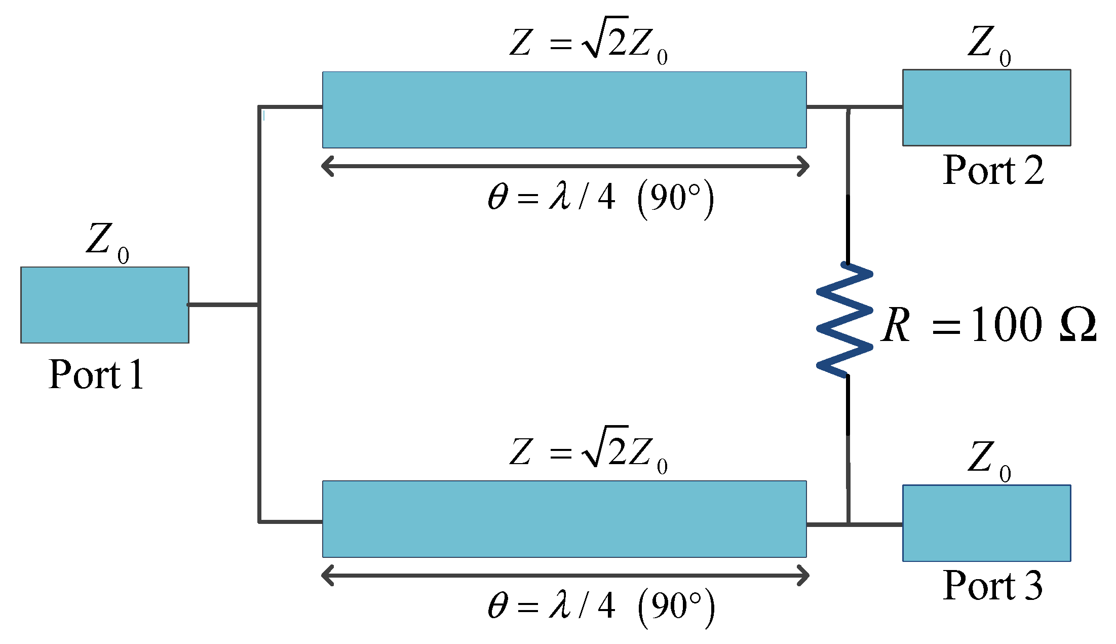
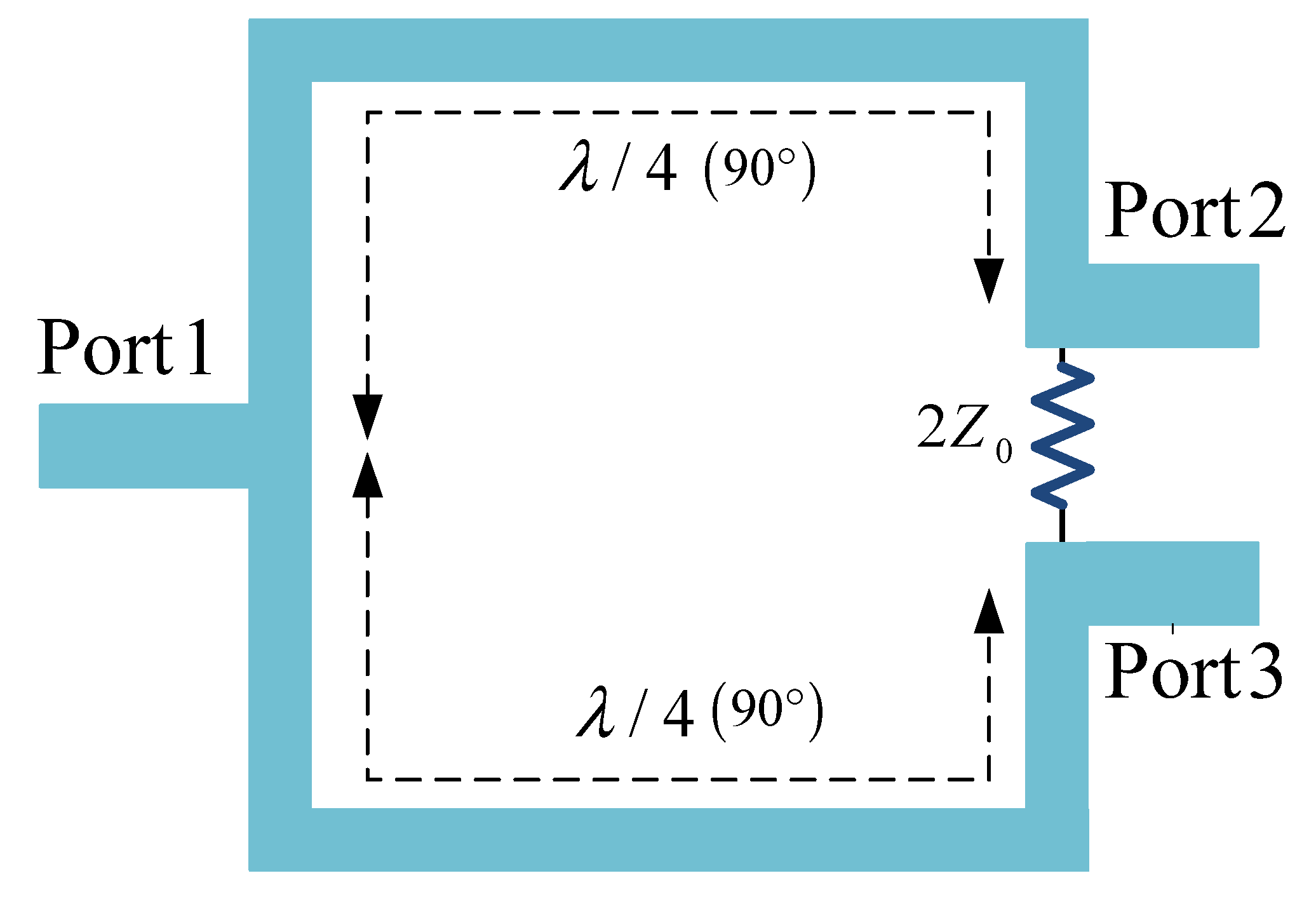
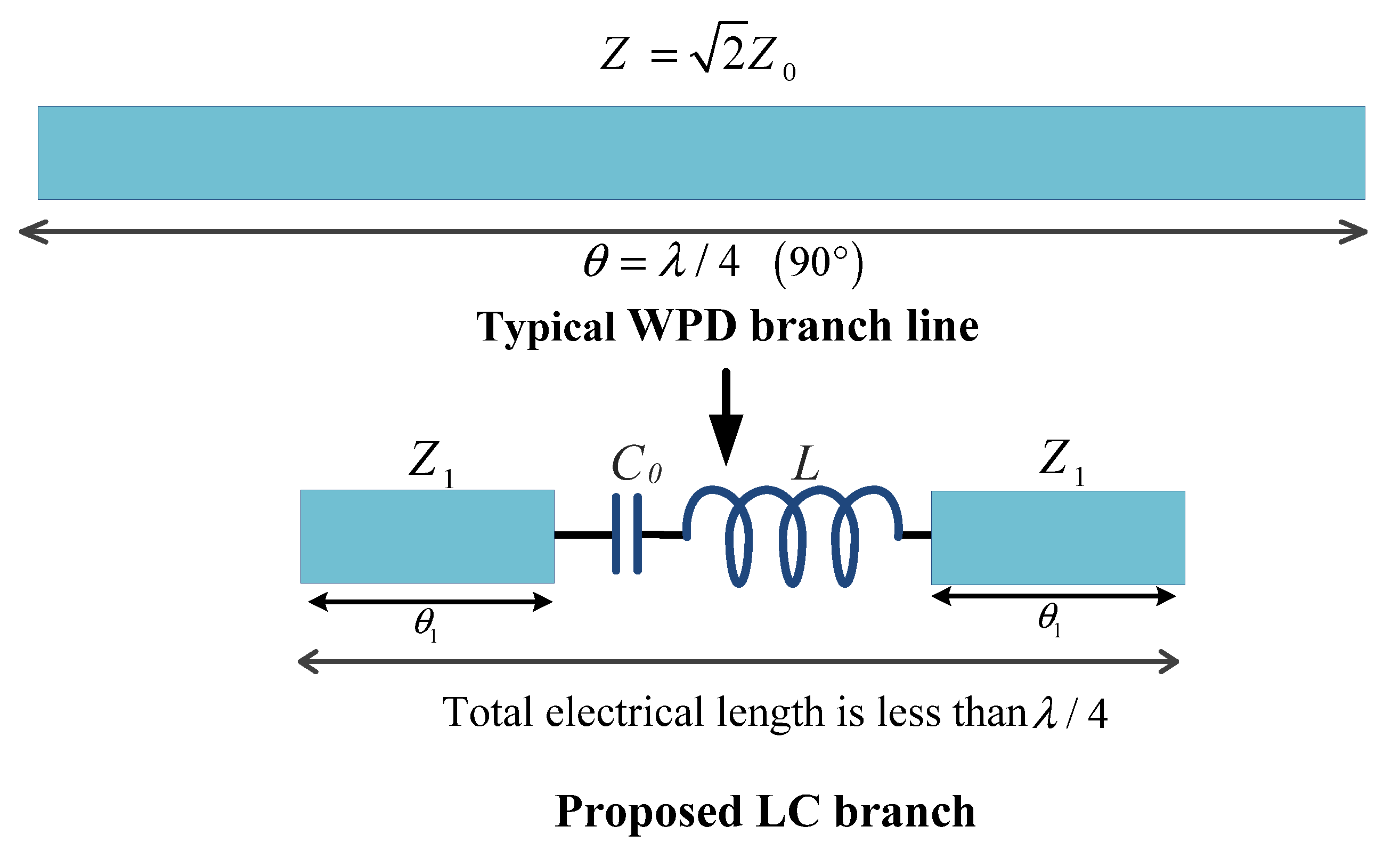
2. Structure of the Typical WPD
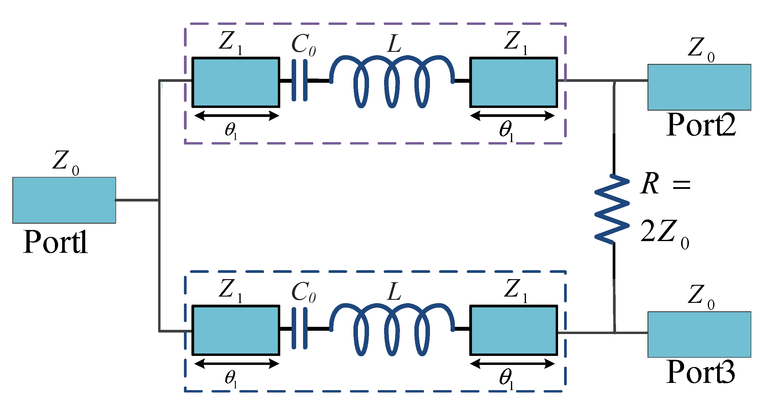
3. Proposed WPD Structure
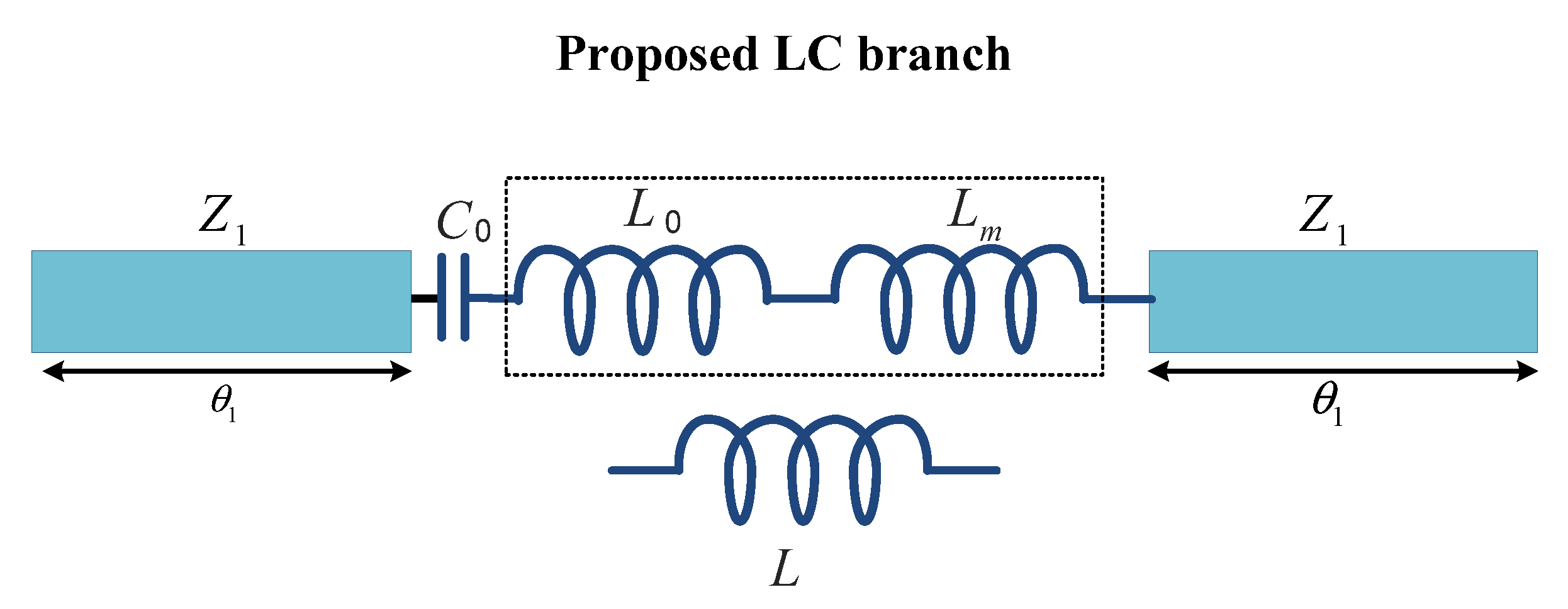
4. Proposed LC Branch Analysis
5. Proposed WPD with LC Branch Analysis
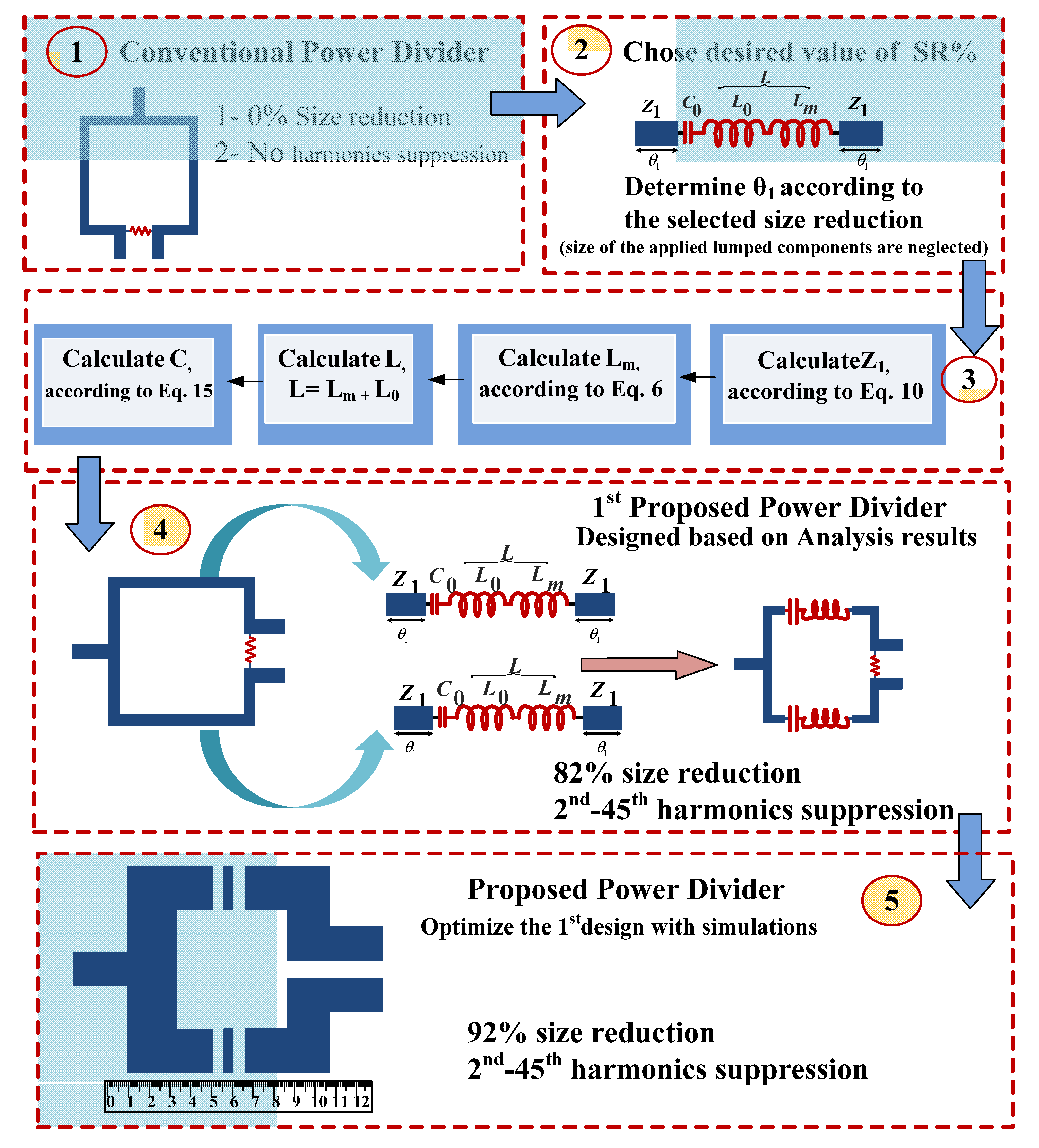
6. The Proposed Power Divider Design
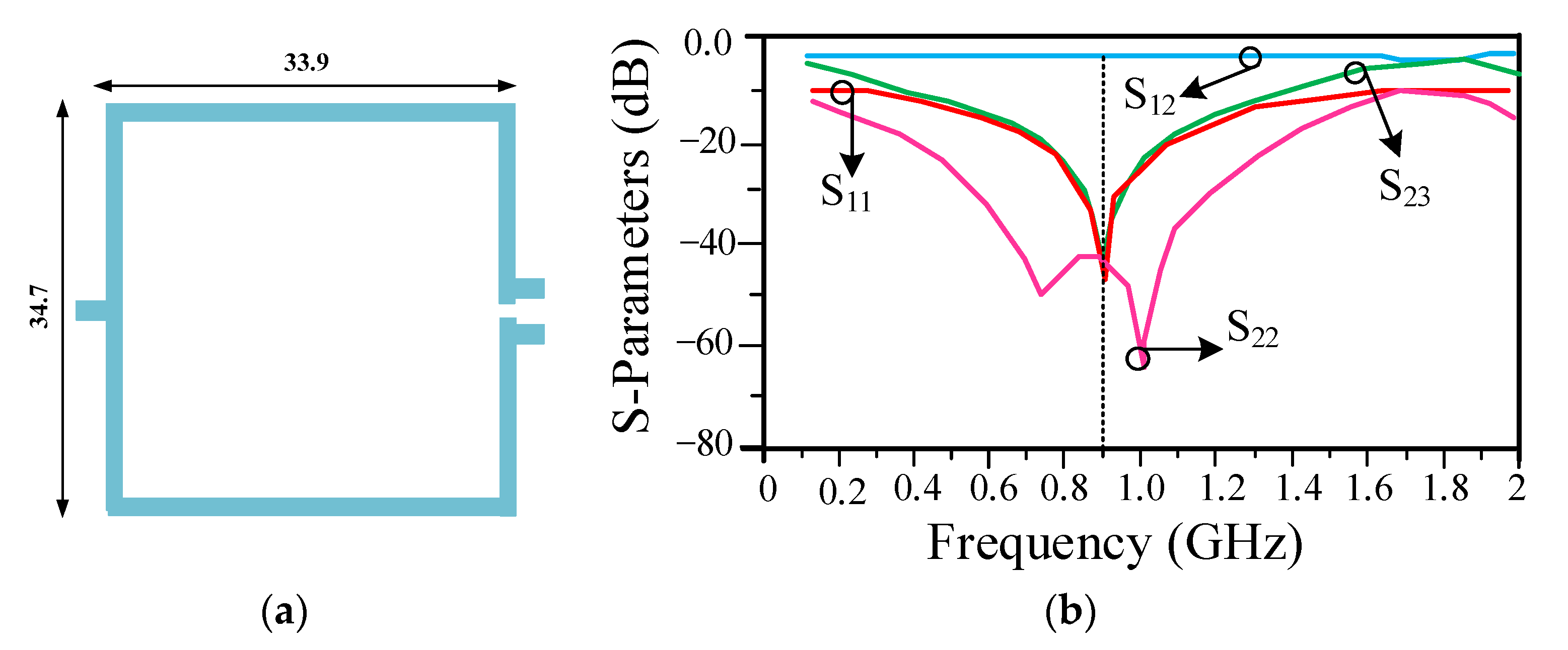
6.1. Typical WPD Design
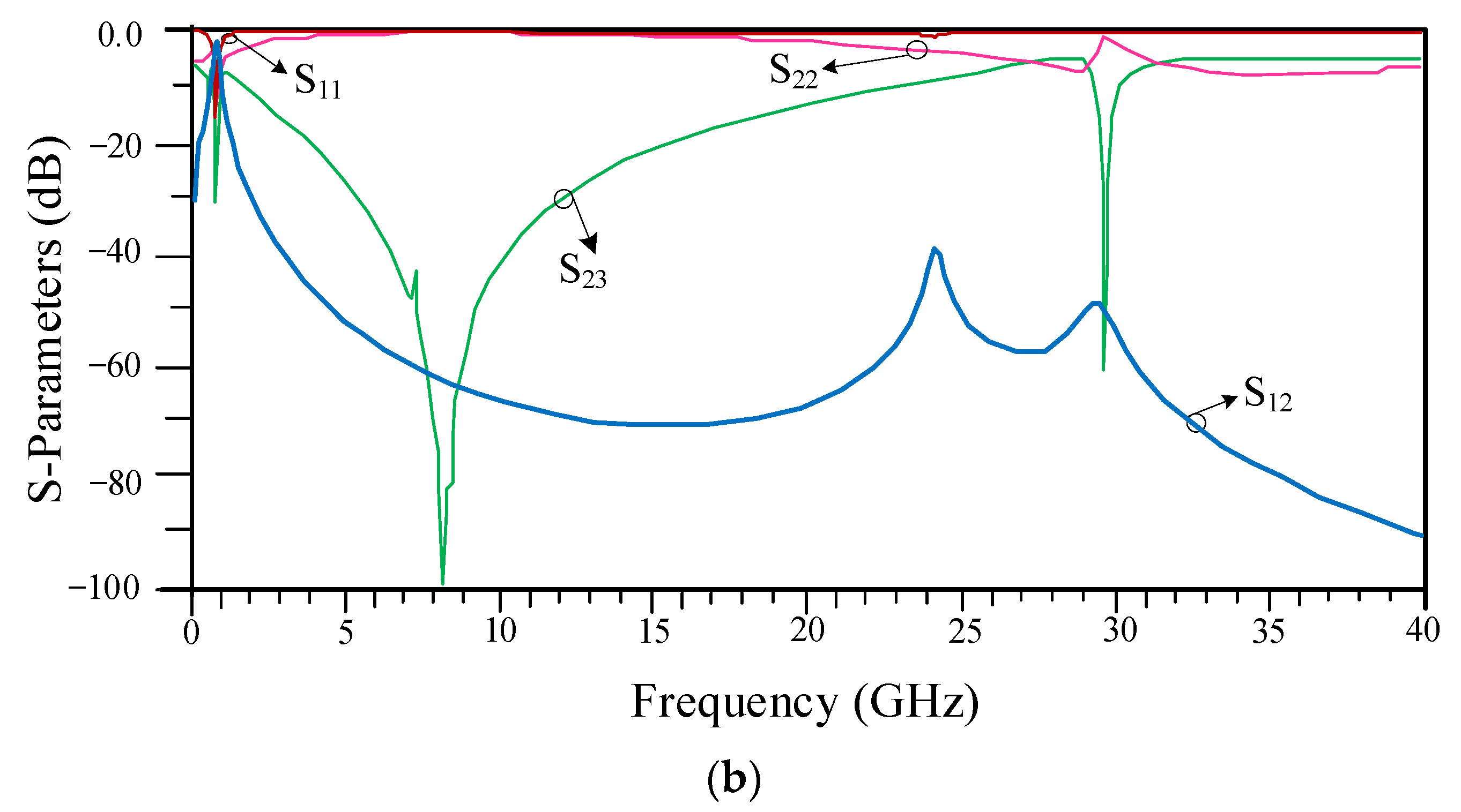
6.2. First Design of the Proposed WPD without Optimization
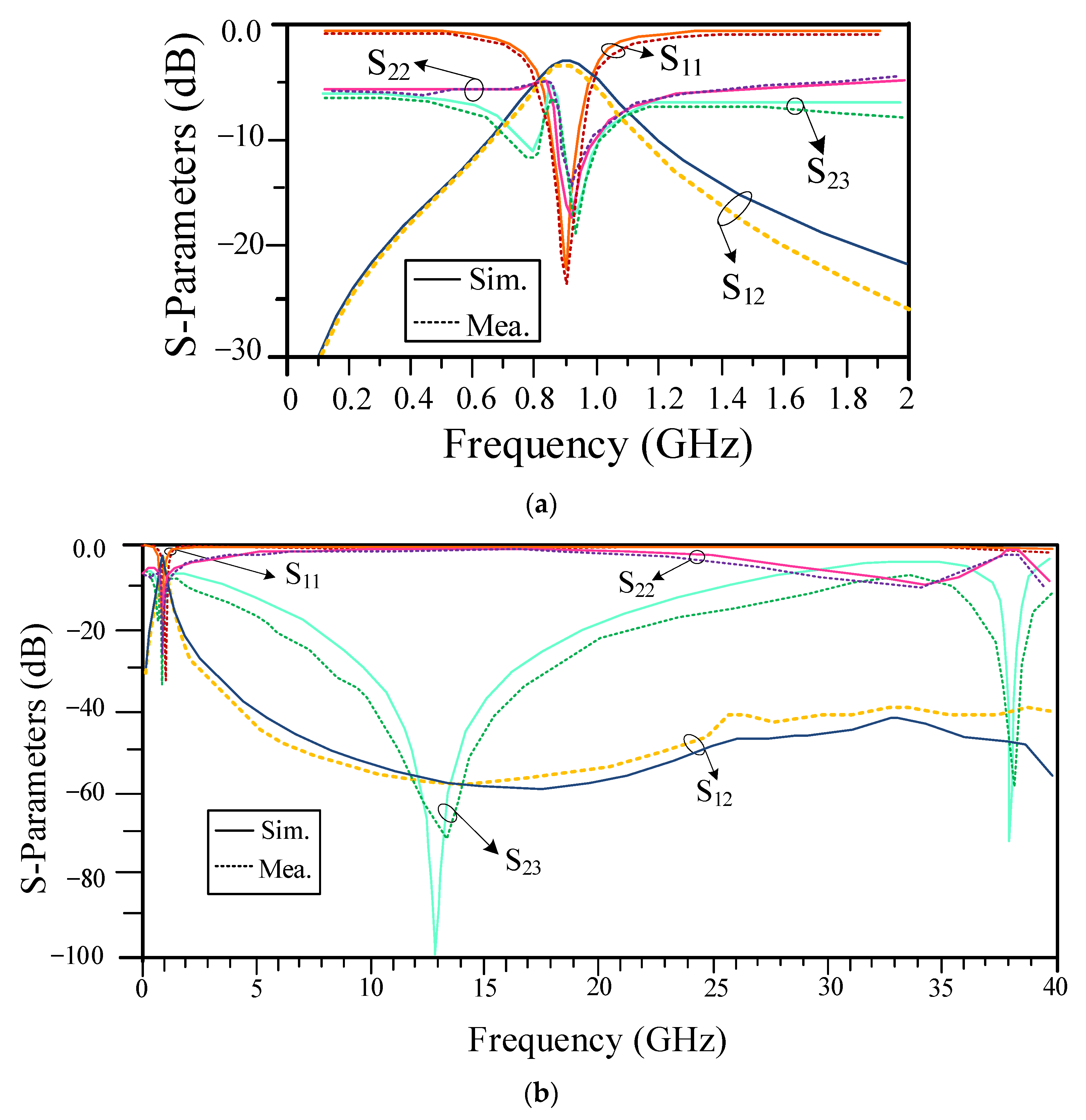
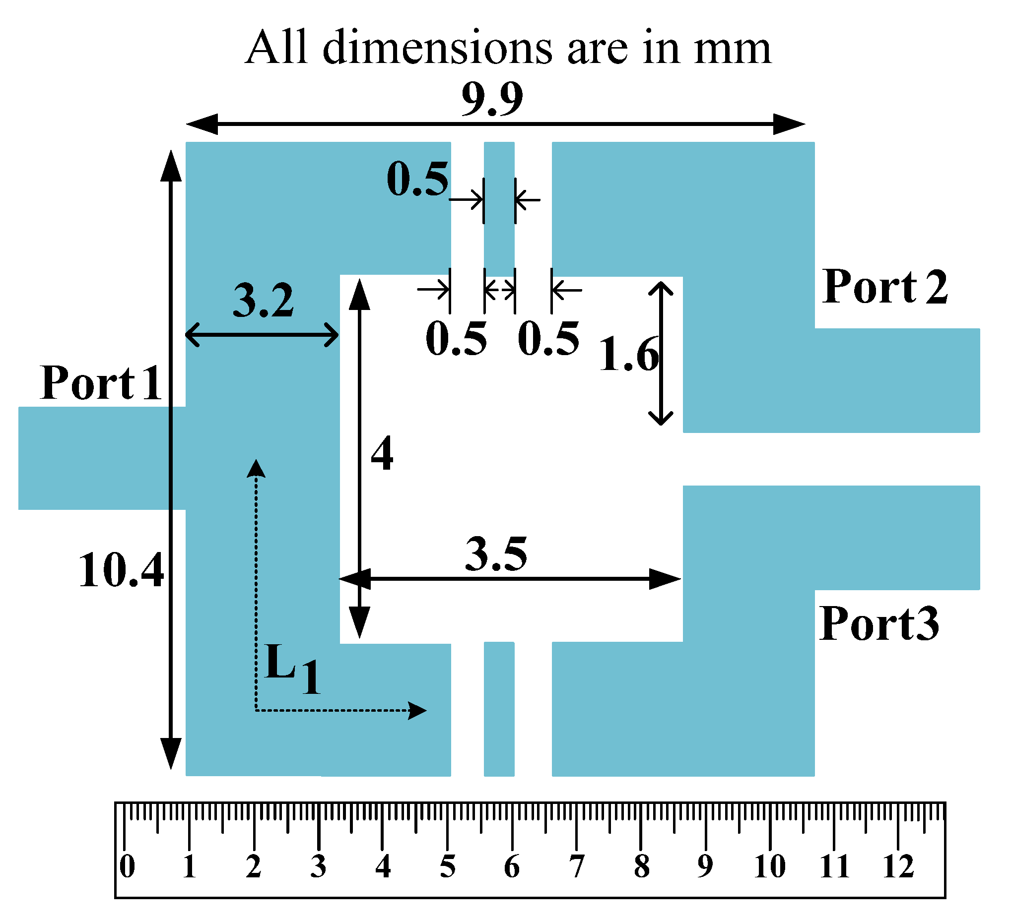
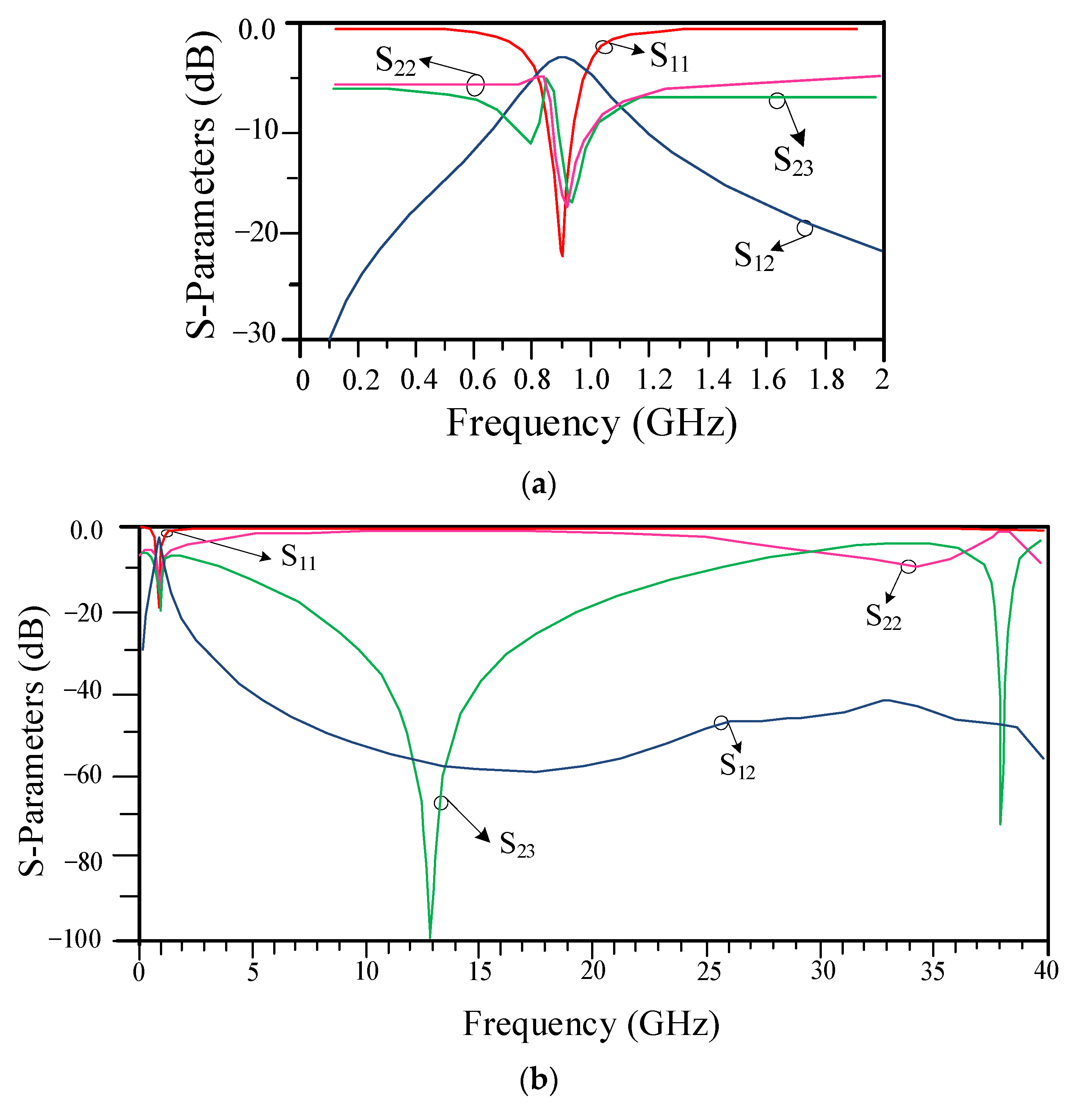
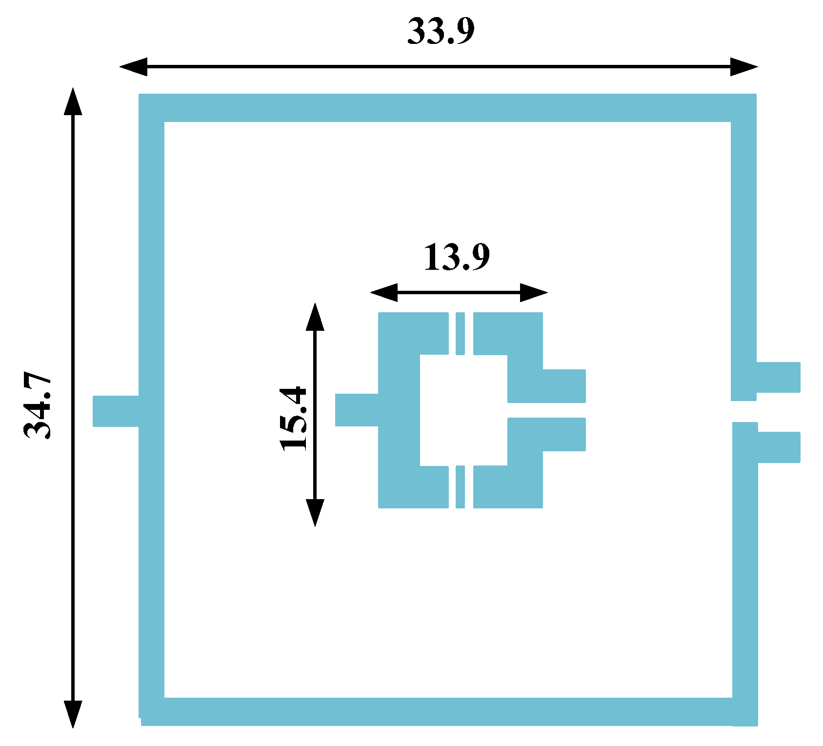
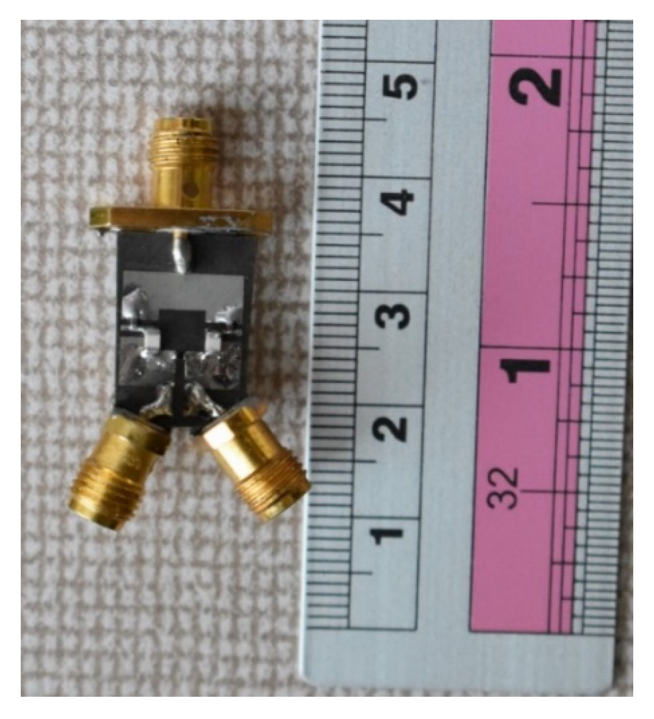
6.3. Second Design of the Proposed WPD with Improvement
7. Conclusions
Author Contributions
Funding
Data Availability Statement
Acknowledgments
Conflicts of Interest
References
- Roshani, S.; Roshani, S.; Zarinitabar, A. A modified Wilkinson power divider with ultra harmonic suppression using open stubs and lowpass filters. Analog Integr. Circuits Signal Process. 2019, 98, 395–399. [Google Scholar] [CrossRef]
- Radanliev, P.; de Roure, D. Review of Algorithms for Artificial Intelligence on Low Memory Devices. IEEE Access 2021, 9, 109986–109993. [Google Scholar] [CrossRef]
- Radanliev, P.; De Roure, D.; Walton, R.; Van Kleek, M.; Montalvo, R.M.; Santos, O.; Maddox, L.; Cannady, S. COVID-19 what have we learned? The rise of social machines and connected devices in pandemic management following the concepts of predictive, preventive and personalized medicine. EPMA J. 2020, 11, 311–332. [Google Scholar] [CrossRef] [PubMed]
- Alharbi, A.G.; Kulkarni, J.; Desai, A.; Sim, C.-Y.; Poddar, A. A Multi-Slot Two-Antenna MIMO with High Isolation for Sub-6 GHz 5G/IEEE802.11ac/ax/C-Band/X-Band Wireless and Satellite Applications. Electronics 2022, 11, 473. [Google Scholar] [CrossRef]
- Kulkarni, J.; Alharbi, A.G.; Desai, A.; Sim, C.-Y.; Poddar, A. Design and Analysis of Wideband Flexible Self-Isolating MIMO Antennas for Sub-6 GHz 5G and WLAN Smartphone Terminals. Electronics 2021, 10, 3031. [Google Scholar] [CrossRef]
- Ko, Y.J.; Park, J.Y.; Bu, J.U. Fully integrated unequal Wilkinson power divider with EBG CPW. IEEE Microw. Wirel. Compon. Lett. 2003, 22, 276–278. [Google Scholar]
- Ooi, B.L. Compact EBG in-phase hybrid-ring equal power divider. IEEE Trans. Microw. Theory Tech. 2005, 53, 2329–2334. [Google Scholar]
- Gupta, N.; Ghosh, P.; Toppo, M. A miniaturized Wilkinson power divider using DGS and fractal structure for GSM application. Prog. Electromagn. Res. Lett. 2011, 27, 25–31. [Google Scholar] [CrossRef]
- Kazerooni, M.; Fartookzadeh, M. Design of a Two Octave Gysel power divider using DGS and DMS. J. Commun. Eng. 2013, 2, 73–88. [Google Scholar]
- Song, K.; Ren, X.; Chen, F.; Fan, Y. Compact in-phase power divider integrated filtering response using spiral resonator. IET Microw. Antennas Propag. 2013, 8, 228–234. [Google Scholar] [CrossRef]
- Liu, H.; Liu, C.; Dai, X.; He, S. Design of novel compact dual-band filtering power divider using stepped-impedance resonators with high selectivity. Int. J. RF Microw. Comput. Eng. 2016, 26, 262–267. [Google Scholar] [CrossRef]
- Li, X.; Shao, Z.; Shen, M.; He, Z. High selectivity tunable filtering power divider based on liquid crystal technology for microwave applications. J. Electromagn. Waves Appl. 2016, 30, 825–833. [Google Scholar] [CrossRef]
- Moloudian, G.; Lalbakhsh, A.; Bahrami, S. A Harmonic-Free Wilkinson Power Divider Using Lowpass Resonators. In Proceedings of the 2022 16th European Conference on Antennas and Propagation (EuCAP), Madrid, Spain, 27 March 2022; pp. 1–4. [Google Scholar]
- Lalbakhsh, A.; Ghaderi, A.; Mohyuddin, W.; Simorangkir, R.B.; Bayat-Makou, N.; Ahmad, M.S.; Lee, G.H.; Kim, K.W. A compact C-band bandpass filter with an adjustable dual-band suitable for satellite communication systems. Electronics 2020, 9, 1088. [Google Scholar] [CrossRef]
- Wang, Y.; Zhang, X.Y.; Liu, F.X.; Lee, J.C. A compact bandpass Wilkinson power divider with ultra-wideband harmonic suppression. IEEE Microw. Wireless Compon. Lett. 2017, 27, 888–890. [Google Scholar] [CrossRef]
- Chen, M.T.; Tang, C.W. Design of the filtering power divider with a wide passband and stopband. IEEE Microw. Wireless Compon. Lett. 2018, 28, 570–572. [Google Scholar] [CrossRef]
- Parandin, F.; Olyaee, S.; Kamarian, R.; Jomour, M. Design and Simulation of Linear All-Optical Comparator Based on Square-Lattice Photonic Crystals. Photonics 2022, 9, 459. [Google Scholar] [CrossRef]
- Parandin, F.; Sheykhian, A. Design and simulation of a 2 × 1 All-Optical multiplexer based on photonic crystals. Opt. Laser Technol. 2022, 151, 108021. [Google Scholar] [CrossRef]
- Roshani, M.; Sattari, M.A.; Ali, P.J.M.; Roshani, G.H.; Nazemi, B.; Corniani, E.; Nazemi, E. Application of GMDH neural network technique to improve measuring precision of a simplified photon attenuation based two-phase flowmeter. Flow Meas. Instrum. 2020, 75, 101804. [Google Scholar] [CrossRef]
- Nazemi, E.; Roshani, G.H.; Feghhi, S.A.; Setayeshi, S.; Zadeh, E.E.; Fatehi, A. Optimization of a method for identifying the flow regime and measuring void fraction in a broad beam gamma-ray attenuation technique. Int. J. Hydrog. Energy 2016, 41, 7438–7444. [Google Scholar] [CrossRef]
- Karimi, G.; Lalbakhsh, A.; Dehghani, K.; Siahkamari, H. Analysis of Novel Approach to Design of Ultra-wide Stopband Microstrip Low-Pass Filter Using Modified U-Shaped Resonator. ETRI J. 2015, 37, 945–950. [Google Scholar] [CrossRef]
- Sariri, H.; Rahmani, Z.; Lalbakhsh, A.; Majidifar, S. Compact LPF Using T-shaped Resonator. Frequenz 2013, 67, 17–20. [Google Scholar] [CrossRef]
- Wang, Z.; Park, C.W. Multiband pi-shaped structure with resonators for tri-band Wilkinson power divider and tri-band rat-race coupler. In Proceedings of the 2012 IEEE/MTT-S International Microwave Symposium Digest, Montreal, QC, Canada, 17–22 June 2012; IEEE: Piscataway Township, NJ, USA; pp. 1–3. [Google Scholar]
- Dehghani, K.; Karimi, G.; Lalbakhsh, A.; Maki, S. Design of lowpass filter using novel stepped impedance resonator. Electron. Lett. 2014, 50, 37–39. [Google Scholar] [CrossRef]
- Zhang, Q.; Zhang, G.; Liu, Z.; Chen, W.; Tang, W. Dual-Band Filtering Power Divider Based on a Single Circular Patch Resonator with Improved Bandwidths and Good Isolation. IEEE Trans. Circuits Syst. II Express Briefs 2021, 68, 3411–3415. [Google Scholar] [CrossRef]
- Chen, S.; Qi, S.; Chen, X.; Sun, G.; Wu, W. Five-way radial filtering power divider using back-to-back quarter-mode substrate-integrated waveguide and microstrip resonator. Electron. Lett. 2021, 57, 888–890. [Google Scholar] [CrossRef]
- Roshani, G.; Hanus, R.; Khazaei, A.; Zych, M.; Nazemi, E.; Mosorov, V. Densityand velocity determination for single-phase flow based on radiotracertechnique and neuralnetworks. Flow Meas. Instrum. 2018, 61, 9–14. [Google Scholar] [CrossRef]
- Hashemi, A.; Dowlatshahi, M.B.; Nezamabadi-Pour, H. Ensemble of feature selection algorithms: A multi-criteria decision-making approach. Int. J. Mach. Learn. Cybern. 2021, 13, 49–69. [Google Scholar] [CrossRef]
- Sattari, M.A.; Roshani, G.H.; Hanus, R.; Nazemi, E. Applicability of time-domain feature extractionmethods and artificial intelligence in two-phaseflow meters based on gamma-ray absorption technique. Measurement 2021, 168, 108474. [Google Scholar] [CrossRef]
- Beiranvand, F.; Mehrdad, V.; Dowlatshahi, M.B. Unsupervised feature selection for image classification: A bipartite matching-based principal component analysis approach. Knowl.-Based Syst. 2022, 250, 109085. [Google Scholar] [CrossRef]
- Mayet, A.M.; Alizadeh, S.M.; Kakarash, Z.A.; Al-Qahtani, A.A.; Alanazi, A.K.; Alhashimi, H.H.; Eftekhari-Zadeh, E.; Nazemi, E. Introducing a Precise System for Determining Volume Percentages Independent of Scale Thickness and Type of Flow Regime. Mathematics 2022, 23, 1770. [Google Scholar] [CrossRef]
- Paniri, M.; Dowlatshahi, M.B.; Nezamabadi-Pour, H. MLACO: A multi-label feature selection algorithm based on ant colony optimization. Knowl.-Based Syst. 2019, 192, 105285. [Google Scholar] [CrossRef]
- Roshani, M.; Phan, G.T.; Ali, P.J.M.; Roshani, G.H.; Hanus, R.; Duong, T.; Corniani, E.; Nazemi, E.; Kalmoun, E.M. Evaluation of flow pattern recognition and void fraction measurement in two phase flow independent of oil pipeline’s scale layer thickness. Alex. Eng. J. 2021, 60, 1955–1966. [Google Scholar] [CrossRef]
- Hashemi, A.; Joodaki, M.; Joodaki, N.Z.; Dowlatshahi, M.B. Ant colony optimization equipped with an ensemble of heuristics through multi-criteria decision making: A case study in ensemble feature selection. Appl. Soft Comput. 2022, 124, 109046. [Google Scholar] [CrossRef]
- Roshani, M.; Phan, G.; Roshani, G.H.; Hanus, R.; Nazemi, B.; Corniani, E.; Nazemi, E. Combination of X-ray tube and GMDH neural network as a nondestructive and potential technique for measuring characteristics of gas-oil–water three phase flows. Measurement 2021, 168, 108427. [Google Scholar] [CrossRef]
- Paniri, M.; Dowlatshahi, M.B.; Nezamabadi-pour, H. Ant-TD: Ant colony optimization plus temporal difference reinforcement learning for multi-label feature selection. Swarm Evol. Comput. 2021, 64, 100892. [Google Scholar] [CrossRef]
- Roshani, M.; Phan, G.; Faraj, R.H.; Phan, N.-H.; Roshani, G.H.; Nazemi, B.; Corniani, E.; Nazemi, E. Proposing a gamma radiation based intelligent system for simultaneous analyzing and detecting type and amount of petroleum by-products. Nucl. Eng. Technol. 2020, 53, 1277–1283. [Google Scholar] [CrossRef]
- Dowlatshahi, M.B.; Derhami, V.; Nezamabadi-Pour, H. Fuzzy particle swarm optimization with nearest-better neighborhood for multimodal optimization. Iran. J. Fuzzy Syst. 2020, 17, 7–24. [Google Scholar]
- Lalbakhsh, A.; Afzal, M.U.; Esselle, K. Simulation-driven particle swarm optimization of spatial phase shifters. In Proceedings of the 18th IEEE international Conference on Electromagnetics in Advanced Applications (ICEAA), Cairns, QLD, Australia, 19–23 September 2016; pp. 428–430. [Google Scholar]
- Jamshidi, M.; Lalbakhsh, A.; Lotfi, S.; Siahkamari, H.; Mohamadzade, B.; Jalilian, J. A neuro-based approach to designing a Wilkinsonpower divider. Int. J. RF Microw. Comput.-Aided Eng. 2020, 30, e22091. [Google Scholar] [CrossRef]
- Cheng, K.M.; Ip, W. A Novel Power Divider Design with Enhanced Spurious Suppression and Simple Structure. IEEE Trans. Microw. Theory Tech. 2010, 58, 3903–3908. [Google Scholar] [CrossRef]
- Lin, C.-M.; Su, H.-H.; Chiu, J.-C.; Wang, Y.-H. Wilkinson Power Divider Using Microstrip EBG Cells for the Suppression of Harmonics. IEEE Microw. Wirel. Compon. Lett. 2007, 17, 700–702. [Google Scholar] [CrossRef]
- Woo, D.J.; Lee, T.K. Suppression of Harmonics in Wilkinson Power Divider Using Dual-Band Rejection by Asymmetric DGS. IEEE Trans. Microw. Theory Tech. 2005, 53, 2139–2144. [Google Scholar]
- Zhang, F.; Li, C. Power divider with microstrip electromagnetic band gap element for miniaturization and harmonic rejection. Electron. Lett. 2008, 44, 422–423. [Google Scholar] [CrossRef]
- Yang, J.; Gu, C.; Wu, W. Design of Novel Compact Coupled Microstrip Power Divider with Harmonic Suppression. IEEE Microw. Wirel. Compon. Lett. 2008, 18, 572–574. [Google Scholar] [CrossRef]
- Li, J.-L.; Qu, S.-W.; Xue, Q. Capacitively loaded Wilkinson power divider with size reduction and harmonic suppression. Microw. Opt. Technol. Lett. 2007, 49, 2737–2739. [Google Scholar] [CrossRef]
- Gu, J.-Z.; Yu, X.-J.; Sun, X.-W. A compact harmonic-suppressed Wilkinson power divider using C-SCMRC resonators. Microw. Opt. Technol. Lett. 2006, 48, 2382–2384. [Google Scholar] [CrossRef]
- Karthikeyan, S.S.; Kshetrimayum, R. Compact, harmonic suppressed power divider using open complementary split-ring resonator. Microw. Opt. Technol. Lett. 2011, 53, 2897–2899. [Google Scholar] [CrossRef]
- He, J.; Feng, Z.; Chen, B.; Yang, H.; Xiong, M.Y. Miniaturized microstrip Wilkinson power divider with capacitor loading. Microw. Opt. Technol. Lett. 2012, 54, 61–63. [Google Scholar] [CrossRef]
- Wang, J.; Ni, J.; Guo, Y.X.; Fang, D. Miniaturized microstrip Wilkinson power divider with harmonic suppression. IEEE Microw. Wirel. Compon. Lett. 2009, 19, 440–442. [Google Scholar] [CrossRef]
- Hazeri, A.R. A New Miniaturization and the nth Harmonic Suppression of Wilkinson Power. IEICE Trans. Electron. 2011, E94.C, 215–219. [Google Scholar] [CrossRef]
- Hayati, M.; Roshani, S.; Roshani, S.; Shama, F. A novel miniaturized Wilkinson power divider with nth harmonic suppression. J. Electromagn. Waves Appl. 2013, 27, 726–735. [Google Scholar] [CrossRef]
- Moradi, E.; Moznebi, A.-R.; Afrooz, K.; Movahhedi, M. Gysel power divider with efficient second and third harmonic suppression using one resistor. AEU-Int. J. Electron. Commun. 2018, 89, 116–122. [Google Scholar] [CrossRef]
- Chao SF &Li, Y.R. Miniature filtering power divider with increased isolation bandwidth. Electron. Lett. 2014, 50, 608–610. [Google Scholar]
- Liu, F.-X.; Wang, Y.; Zhang, X.-Y.; Quan, C.-H.; Lee, J.-C. A Size-Reduced Tri-Band Gysel Power Divider with Ultra-Wideband Harmonics Suppression Performance. IEEE Access 2018, 6, 34198–34205. [Google Scholar] [CrossRef]
- Roshani, S.; Jamshidi, M.B.; Mohebi, F.; Roshni, S. Design and Modeling of a Compact Power Divider with Squared Resonators Using Artificial Intelligence. Wirel. Pers. Commun. 2021, 117, 2085–2096. [Google Scholar] [CrossRef]
- Heydari, M.; Roshani, S. Miniaturized Harmonic Suppressed Wilkinson Power Divider using Lumped Components and Resonators. Wirel. Pers. Commun. 2021, 117, 1527–1536. [Google Scholar] [CrossRef]
- Zhan, W.-L.; Zhao, X.-L. Compact filtering power divider with harmonic suppression. J. Electromagn. Waves Appl. 2016, 31, 243–249. [Google Scholar] [CrossRef]
- Li, J.L.; Wang, H.Z.; Wang, J.P.; Gao, S.S.; Yang, X.S.; Shao, W. Miniaturized Wilkinson power dividers with harmonic suppressions. Electromagnetics 2016, 36, 157–166. [Google Scholar] [CrossRef]
- Mirzavand, R.; Honari, M.M.; Abdipour, A.; Moradi, G. Compact microstrip Wilkinson power dividers with harmonic suppression and arbitrary power division ratios. IEEE Trans. Microw. Theory Tech. 2013, 61, 61–68. [Google Scholar] [CrossRef]
- Hayati, M.; Roshani, S. A novel Wilkinson power divider using open stubs for the suppression of harmonics. ACES 2013, 28, 501–506. [Google Scholar]
- Lotfi, S.; Roshani, S.; Roshani, S.; Gilan, M.S. Wilkinson power divider with band-pass filtering response and harmonics suppression using open and short stubs. Frequenz 2020, 74, 169–176. [Google Scholar] [CrossRef]
- Lotfi, S.; Roshani, S.; Roshni, S. Design of a miniaturized planar microstrip Wilkinson power divider with harmonic cancellation. Turk. J. Electr. Eng. Comput. Sci. 2020, 28, 3126–3136. [Google Scholar]
- Roshani, S.; Roshani, S. Design of a compact LPF and a miniaturized Wilkinson power divider using aperiodic stubs with harmonic suppression for wireless applications. Wirel. Netw. 2020, 26, 1493–1501. [Google Scholar] [CrossRef]
- Jamshidi, M.B.; Roshani, S.; Talla, J.; Roshani, S.; Peroutka, Z. Size reduction and performance improvement of a microstrip Wilkinson power divider using a hybrid design technique. Sci. Rep. 2021, 11, 7773. [Google Scholar] [CrossRef]


| Values | Analysis | 1st Design | 2nd Design | Fabrication |
|---|---|---|---|---|
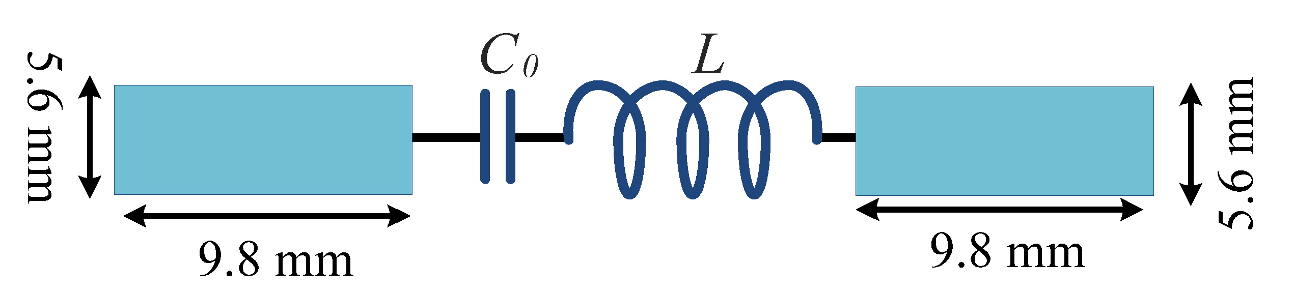
| W (mm) | 5.6 | 5.3 | 3.2 | 3.2 |
| L1 (mm) | 9.8 | 9.4 | 6.5 | 6.5 |
| L (nH) | 73.5 | 66 | 68.3 | 68 |
| C (pF) | 0.5 | 0.43 | 0.43 | 0.43 |
| f (MHz) | 900 | 900 | 900 | 900 |
| Size Reduction | 90% | 82% | 92% | 92% |
| Harmonics Suppression | ∞ | 2nd–45th | 2nd–45th | 2nd–45th |
| Ref | Freq (GHz) | Size Reduction | Number of Harmonics Suppression | Methods |
|---|---|---|---|---|
| [41] | 1 | 0% | 2nd–4th | Open stubs |
| [42] | 2.4 | 70% | 2nd–5th | EBG Cells |
| [43] | 1.5 | 0% | 2nd–3rd | DGS Cells |
| [44] | 2.4 | 39% | 2nd-3rd | EBG Cells |
| [45] | 0.9 | 66% | 2nd–3rd | Coupled Line |
| [46] | 1.5 | 0% | 2nd–3rd | Lumped Capacitor |
| [47] | 2.4 | 44% | 2nd–3rd | Resonator Cell |
| [48] | 0.9 | 47% | 3rd | Resonator Cell |
| [49] | 1 | 55% | 2nd–5th | Open Stubs |
| [50] | 2.65 | 63% | 3rd and 5th | Open Stubs |
| [51] | 1 | 54% | 2nd–7th | Open Stubs |
| [52] | 1 | 71% | 2nd–12th | Resonator Cell & Open Stubs |
| [53] | 1 | 0% | 2nd–3rd | Open Stubs |
| [54] | 1 | 0% | 2nd | Open And Short Stubs |
| [55] | 2 | 0% | 2nd | Resonator Cell & Open Stubs |
| [56] | 1.9 | 55 % | 2nd–4th | Resonator Cell |
| [57] | 1.5 | 52% | 3rd–6th | Lumped Element & Resonator Cell |
| [58] | 2.4 | 0% | 2nd–3rd | Resonator Cell |
| [59] | 1.5 | 16% | 3rd–4th | Lumped Capacitor |
| [60] | 1 | 60% | 2nd–4th | Lumped Inductor |
| [61] | 1.65 | 35% | 3rd and 5th | Open Stubs |
| [62] | 0.9 | 0% | 2nd–4th | Open And Short Stubs |
| [63] | 2 | 50% | 2nd–14th | Resonator Cell |
| [64] | 0.7 | 73% | 2nd–15th | Aperiodic Open Stubs |
| [65] | 0.8 | 82.8% | 2nd–25th | LC Branches |
| This Work | 0.9 | 92% | 2nd–45th | LC Branches |
Publisher’s Note: MDPI stays neutral with regard to jurisdictional claims in published maps and institutional affiliations. |
© 2022 by the authors. Licensee MDPI, Basel, Switzerland. This article is an open access article distributed under the terms and conditions of the Creative Commons Attribution (CC BY) license (https://creativecommons.org/licenses/by/4.0/).
Share and Cite
Roshani, S.; Yahya, S.I.; Alameri, B.M.; Mezaal, Y.S.; Liu, L.W.Y.; Roshani, S. Filtering Power Divider Design Using Resonant LC Branches for 5G Low-Band Applications. Sustainability 2022, 14, 12291. https://doi.org/10.3390/su141912291
Roshani S, Yahya SI, Alameri BM, Mezaal YS, Liu LWY, Roshani S. Filtering Power Divider Design Using Resonant LC Branches for 5G Low-Band Applications. Sustainability. 2022; 14(19):12291. https://doi.org/10.3390/su141912291
Chicago/Turabian StyleRoshani, Saeed, Salah I. Yahya, Ban M. Alameri, Yaqeen Sabah Mezaal, Louis W. Y. Liu, and Sobhan Roshani. 2022. "Filtering Power Divider Design Using Resonant LC Branches for 5G Low-Band Applications" Sustainability 14, no. 19: 12291. https://doi.org/10.3390/su141912291
APA StyleRoshani, S., Yahya, S. I., Alameri, B. M., Mezaal, Y. S., Liu, L. W. Y., & Roshani, S. (2022). Filtering Power Divider Design Using Resonant LC Branches for 5G Low-Band Applications. Sustainability, 14(19), 12291. https://doi.org/10.3390/su141912291