
Behaviour and Design of Bolt-Coupler Connections under Compression in Prefabricated CFST Columns


Abstract
:1. Introduction
2. Experimental Investigation
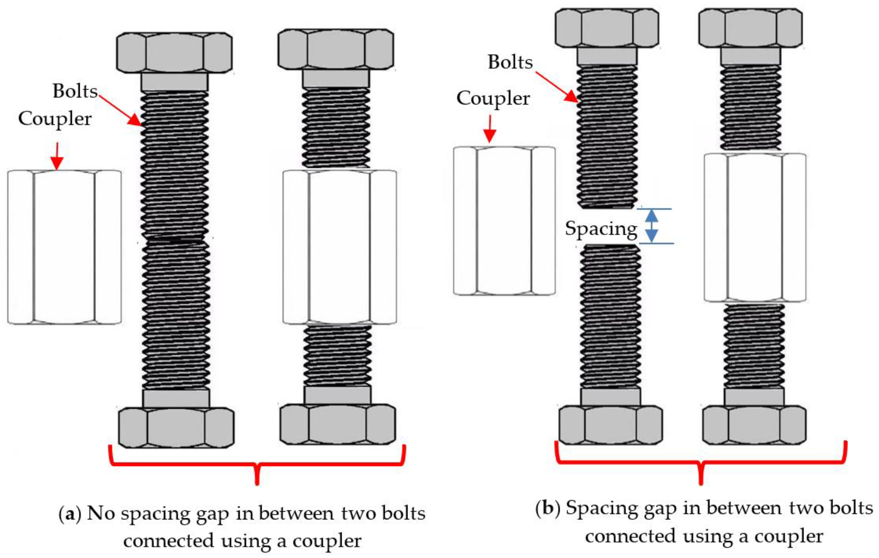
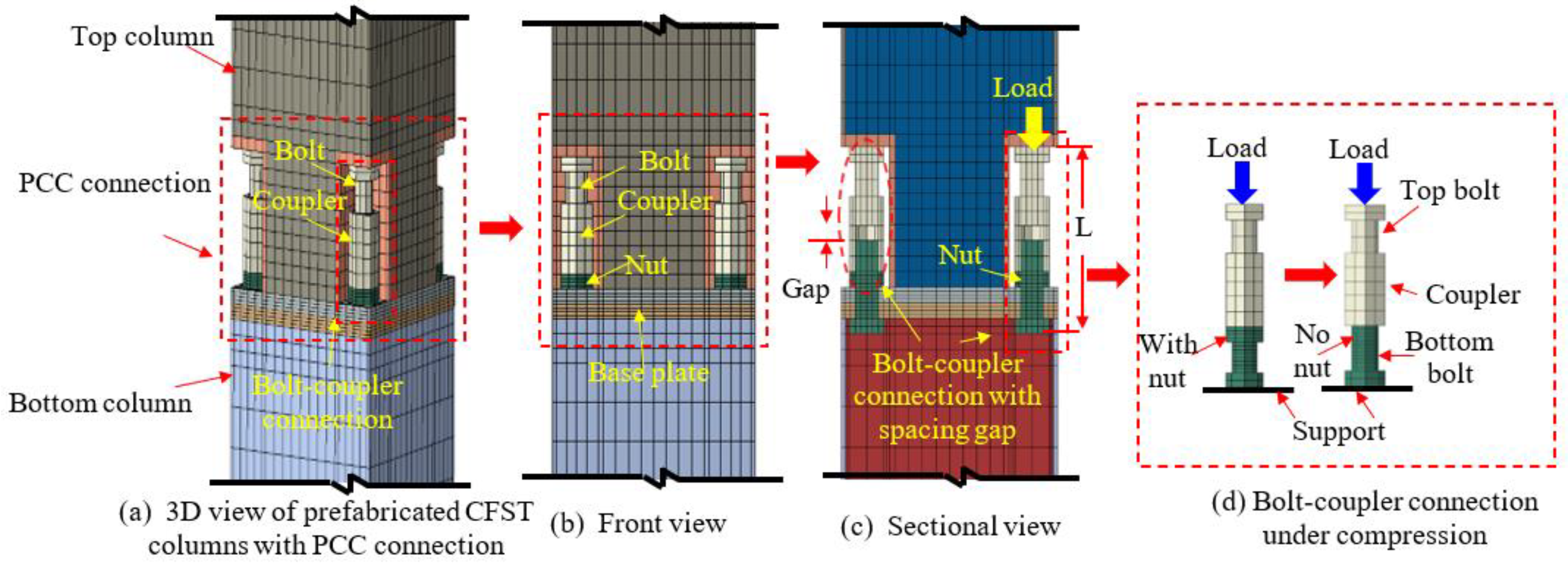
2.1. Test Specimens Designed Concept
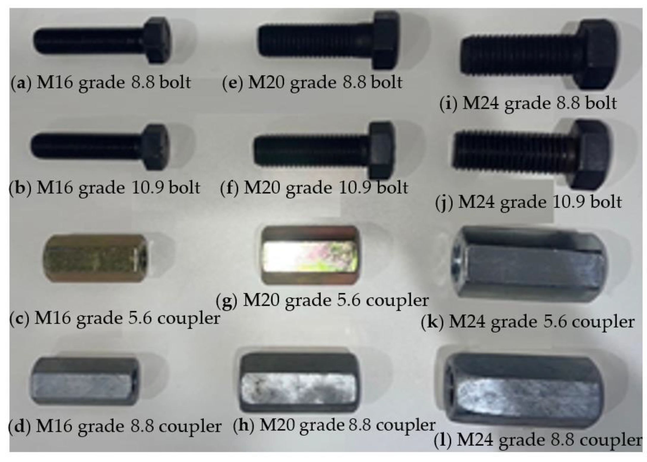
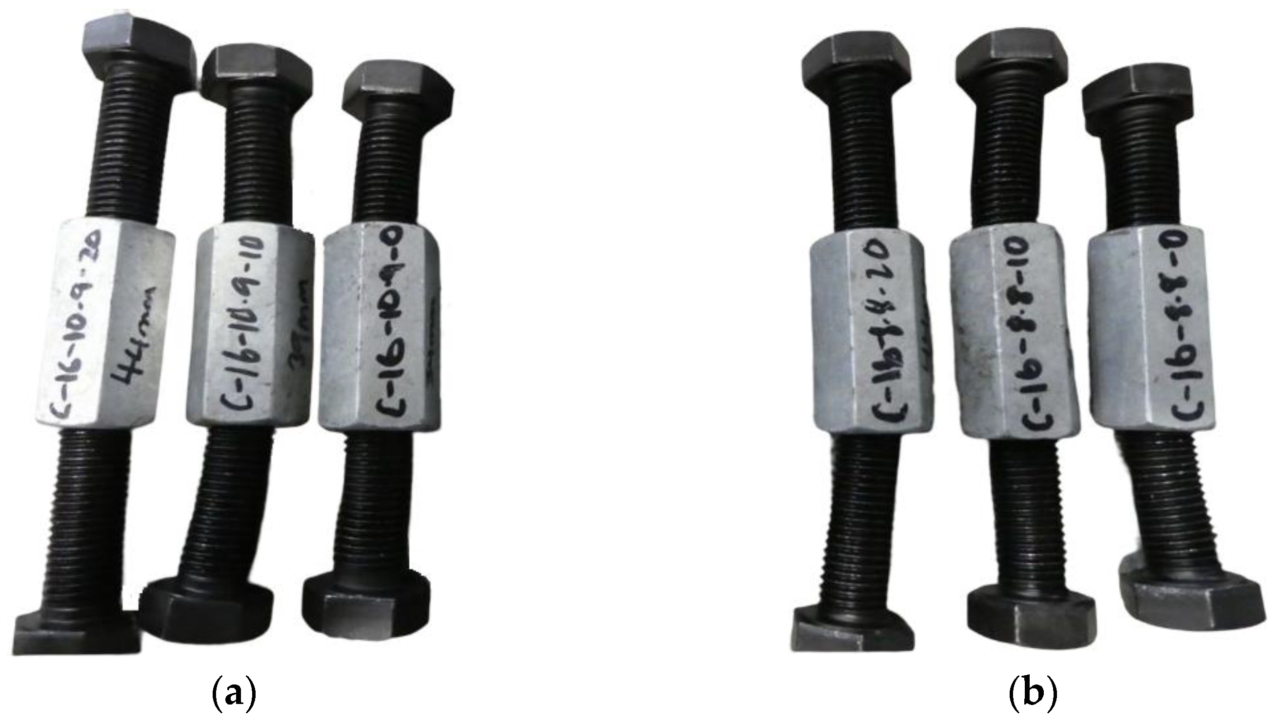
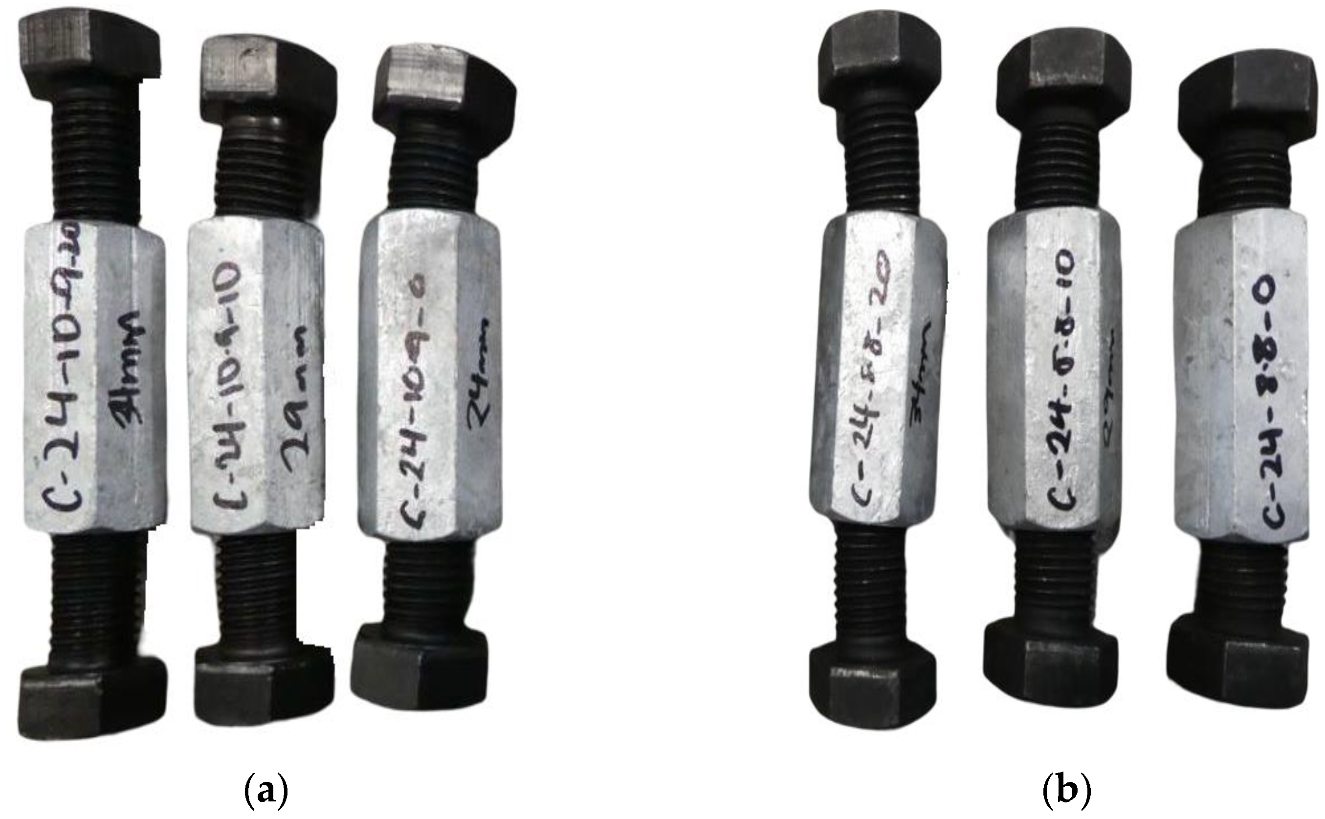
2.2. Test Specimens
2.3. Material Properties
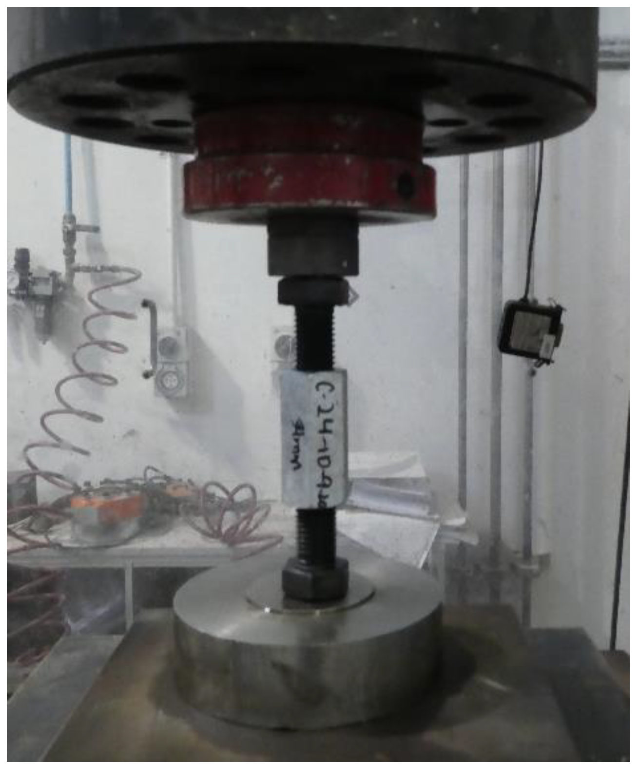
2.4. Test Set up and Testing Procedures
3. Results and Discussion
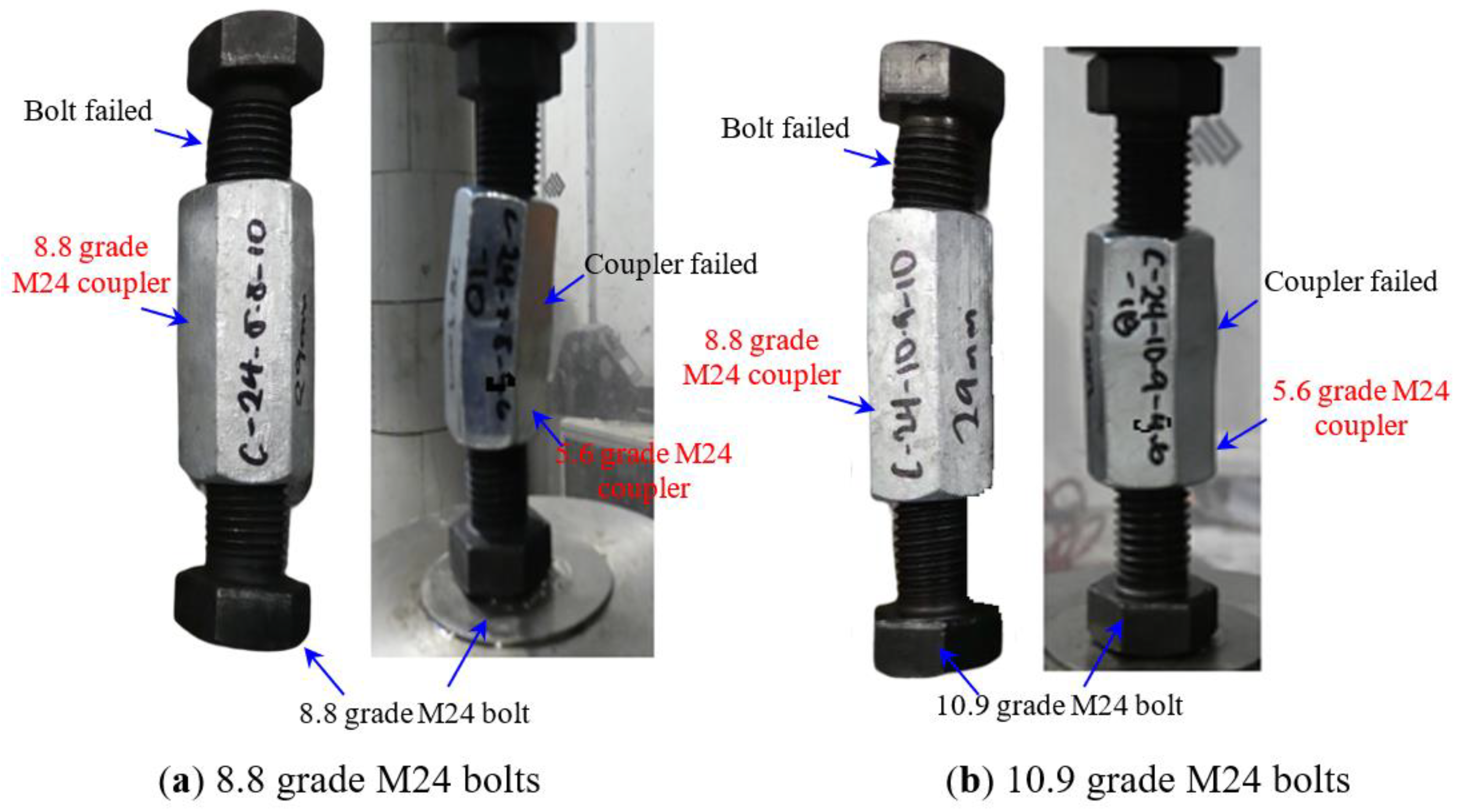
3.1. Failure Modes of Bolt-Coupler Connections
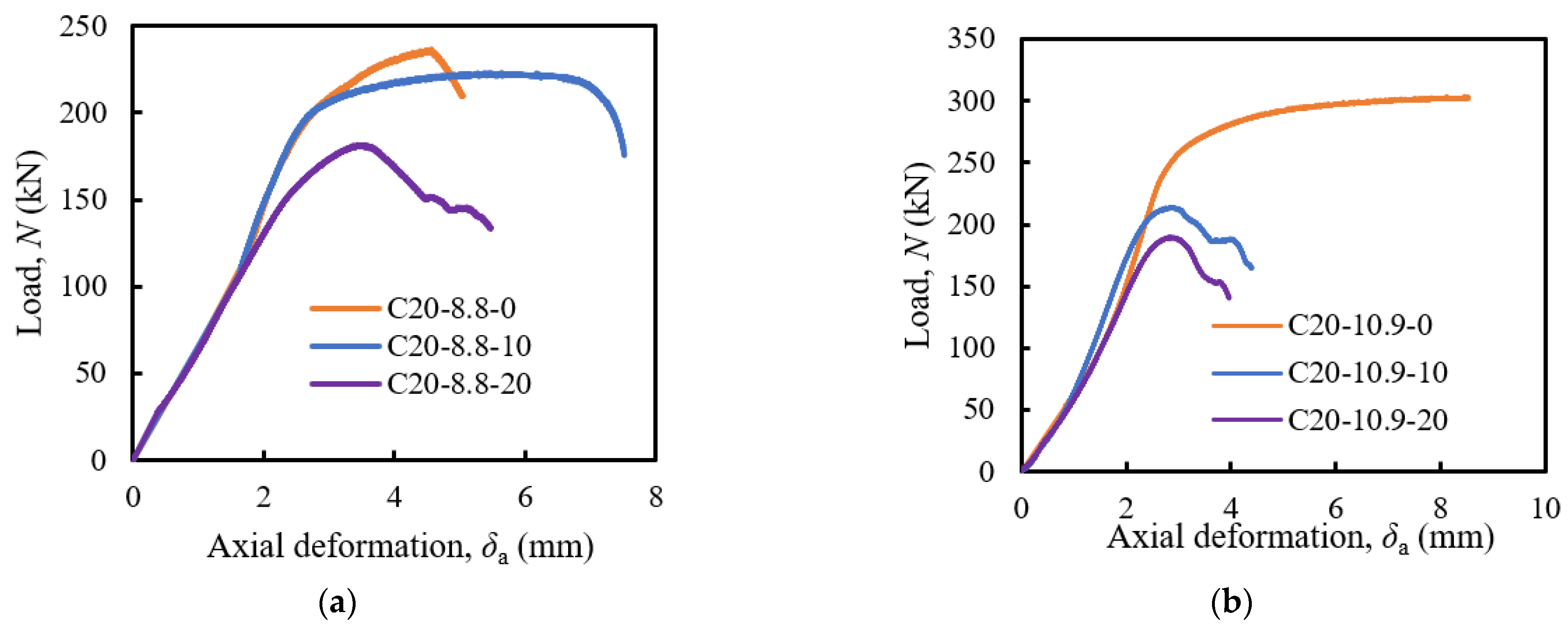
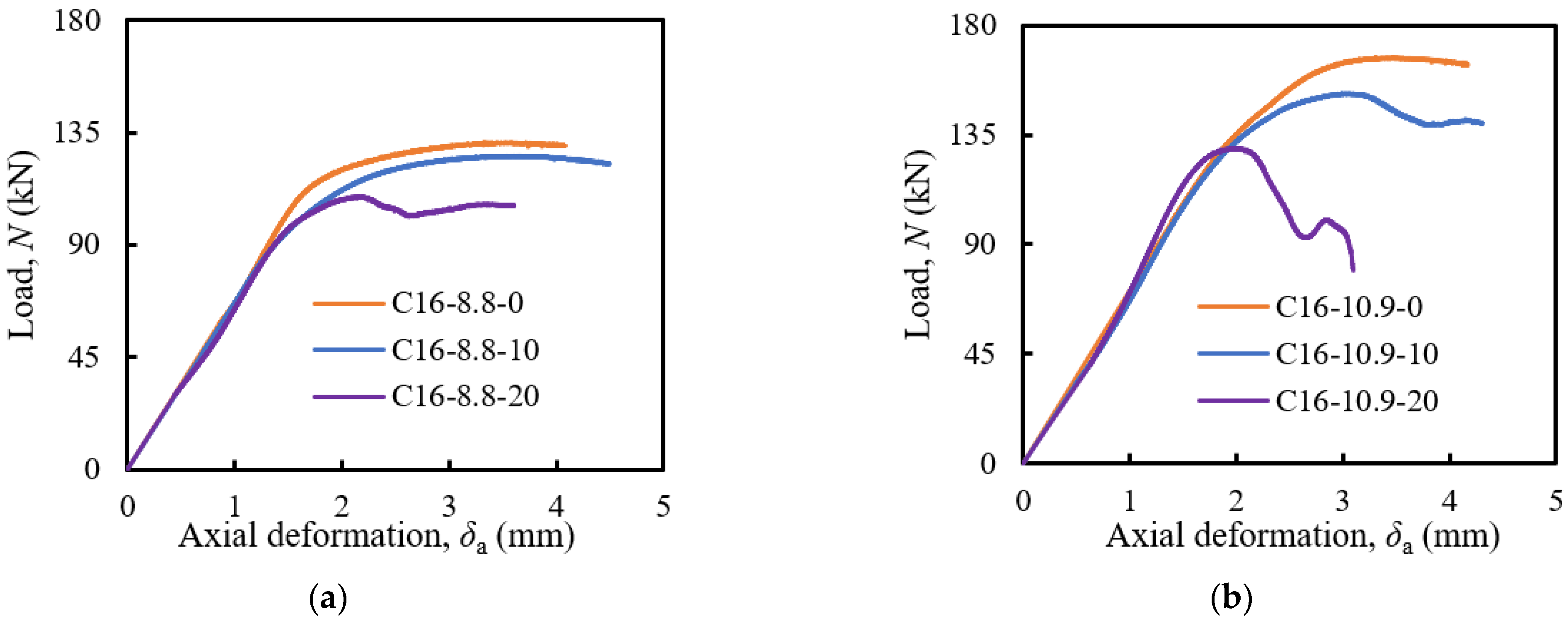
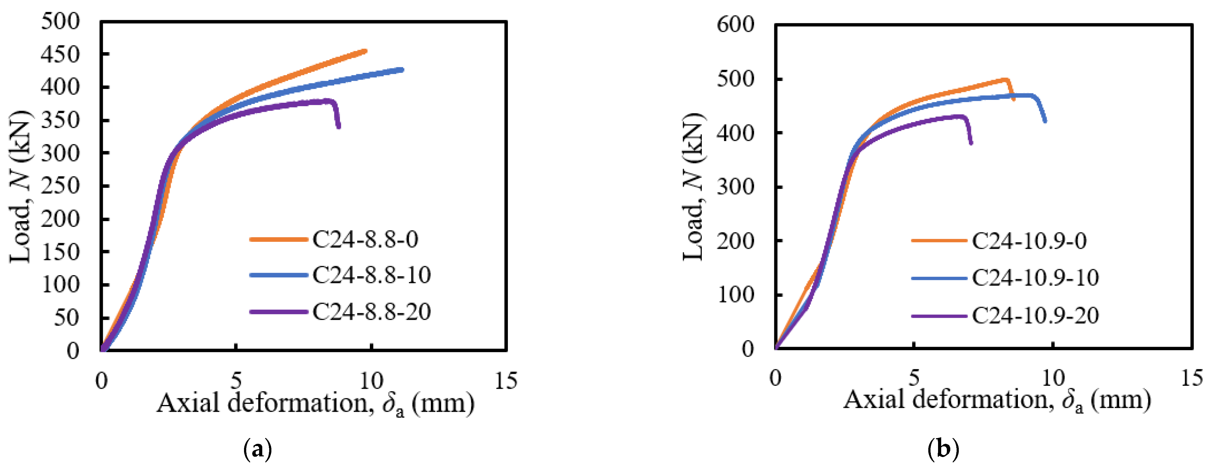
3.2. Load-Deformation Curve of Bolt-Coupler Connections
3.3. Discussion
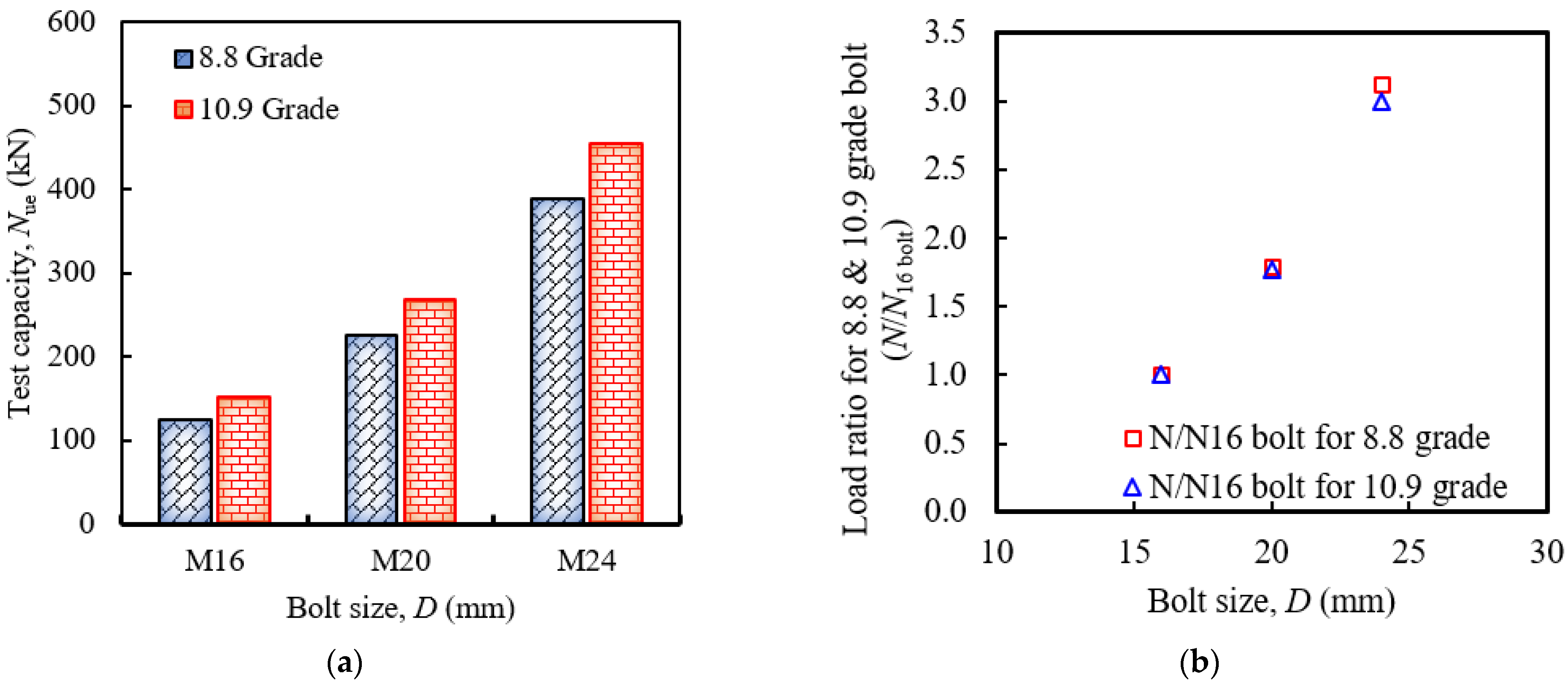
3.3.1. Behaviour of Bolt-Bolt Connections with Coupler Compared to Single Bolts
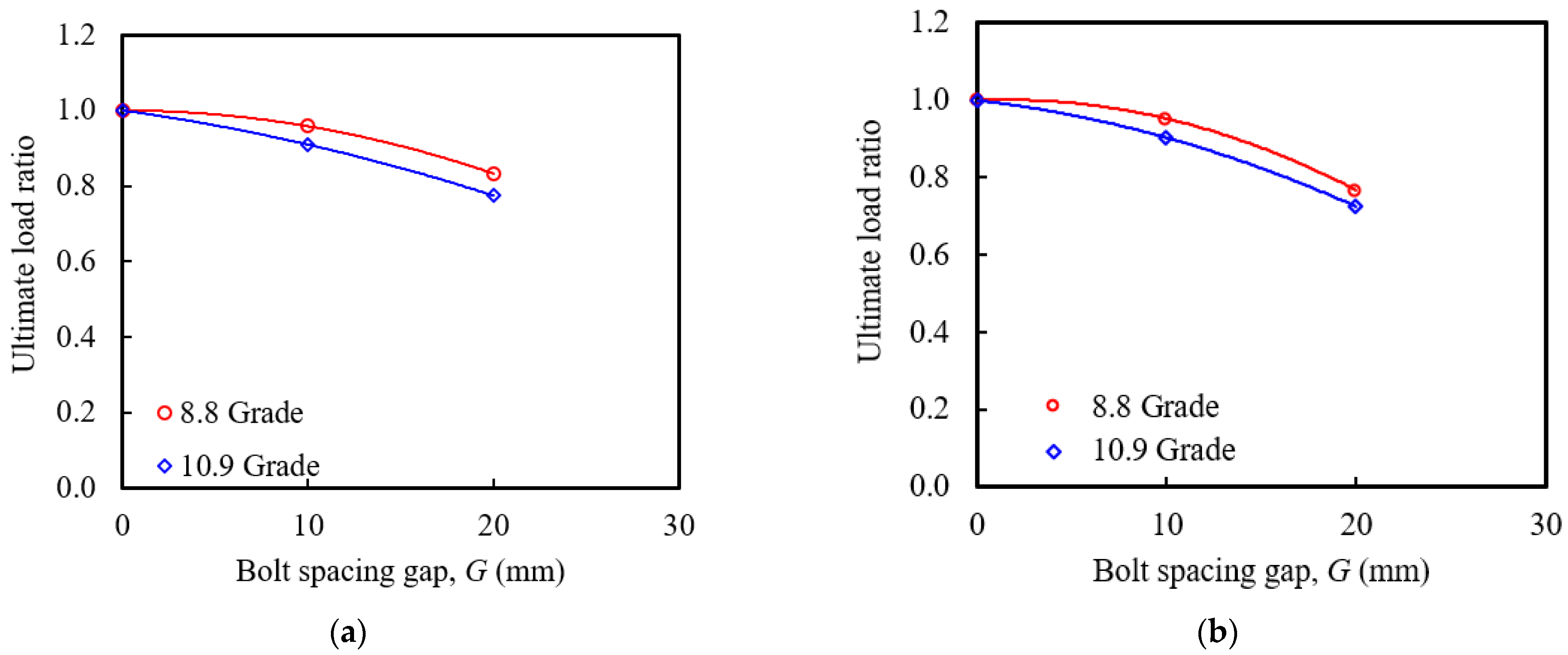
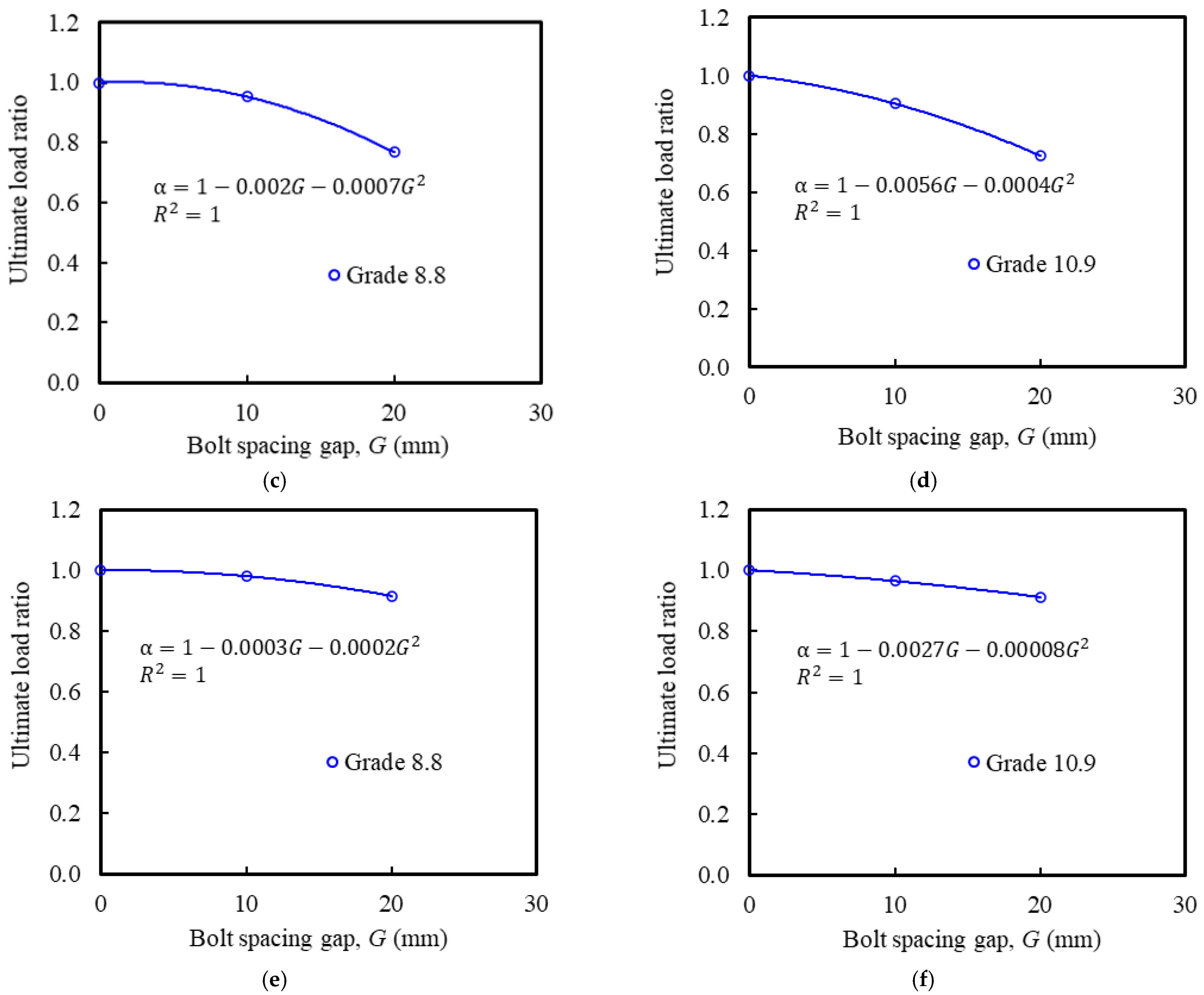
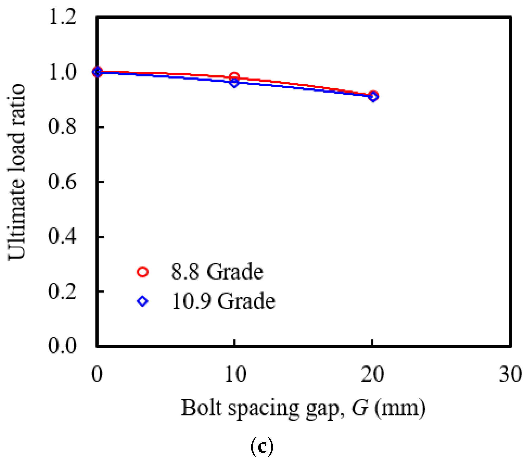
3.3.2. Effect of Bolts Spacing Gap
3.3.3. Effect of Bolt Diameters and Grades
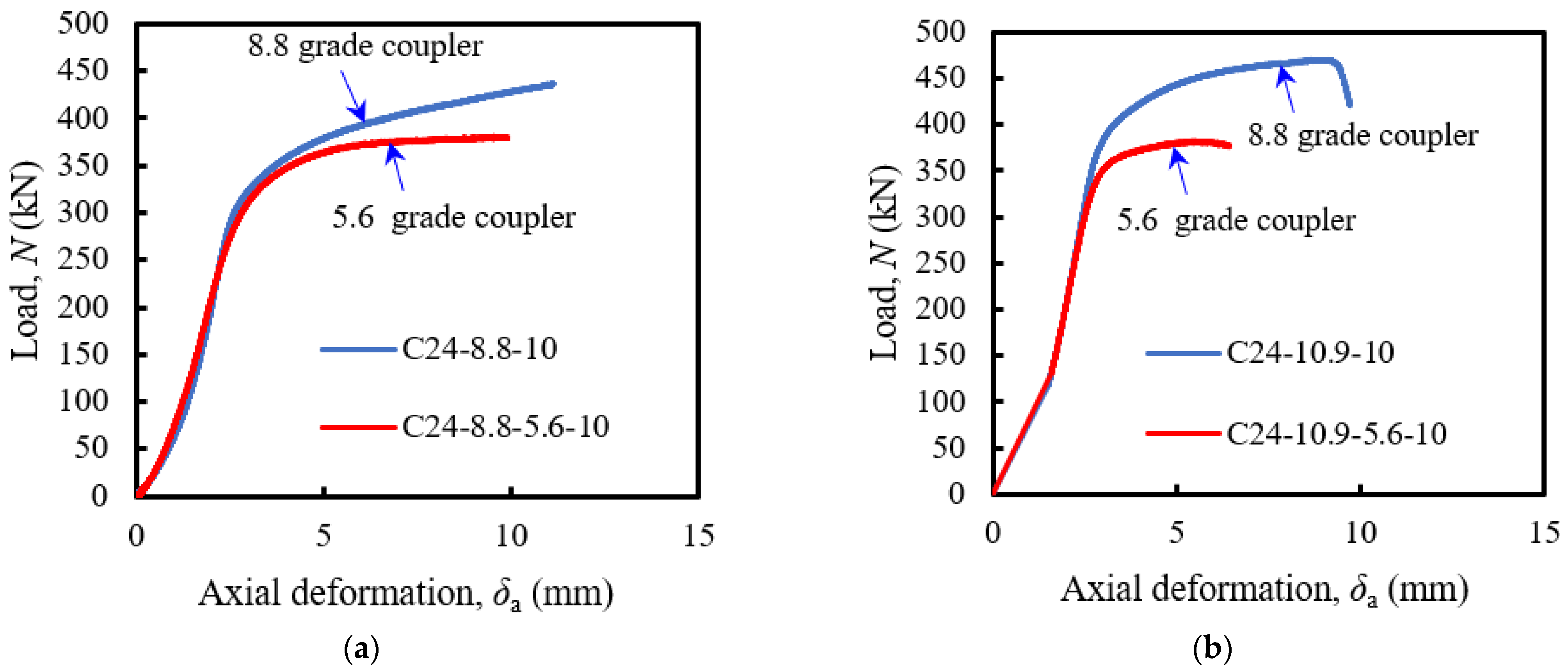
3.3.4. Effect of Coupler Grades
4. Design Capacity of Bolt-Coupler Connections
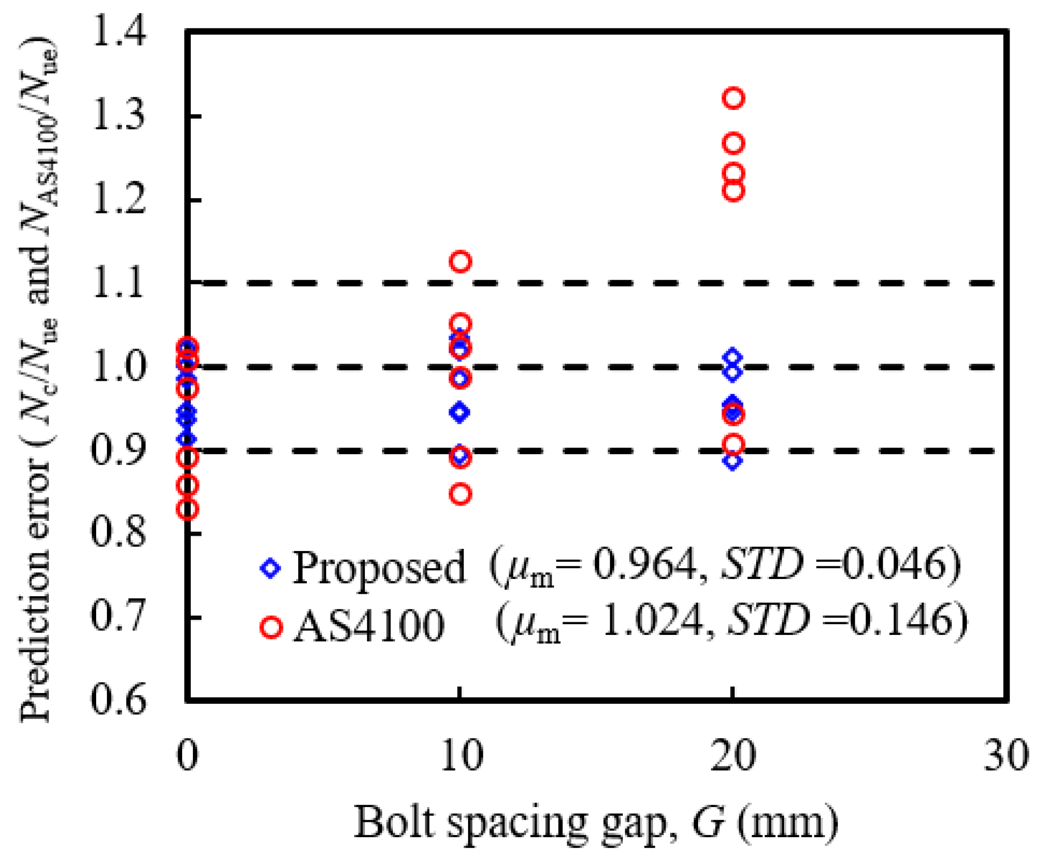
4.1. Test Data Comparison with AS 4100
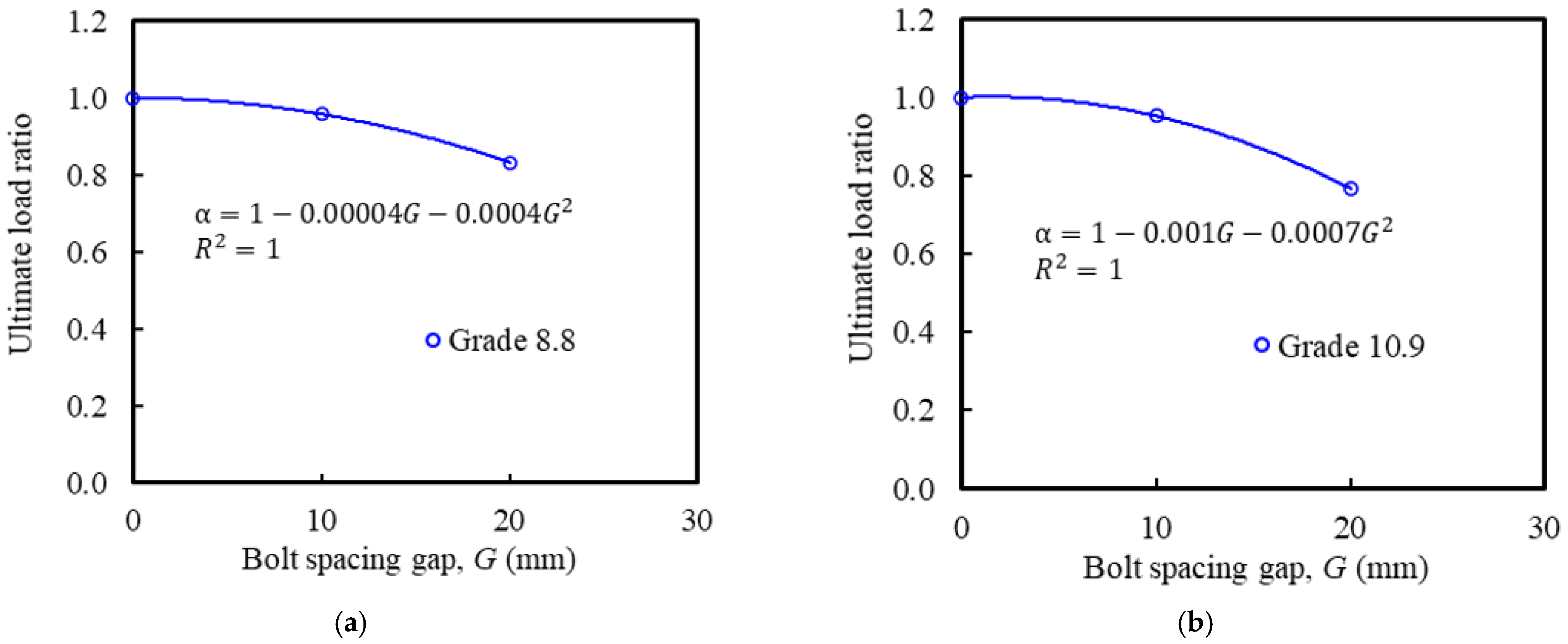
4.2. Design Recommendations
5. Conclusions
- (1)
- The failure modes of bolt-coupler connections mainly depend on the bolt spacing gaps and coupler strength. When the bolt spacing gap was zero, the failure of bolt-coupler connections with 8.8 grade bolts was due to the yielding of the upper bolt and the coupler did not experience any damage. When there was no gap between upper and lower bolts, there was coupler thread failure and yielding of the bolt.
- (2)
- The coupler outward buckling was observed for the lower-grade couplers (5.6 grade) used in bolt-coupler connections. To avoid the coupler failure of bolt-coupler connections, 8.8 grade coupler should be sufficient when the bolt of 8.8 and 10.9 grade are in the bolt-coupler connections.
- (3)
- The ultimate load capacity of bolt-coupler connections with zero spacing gap was observed lower compared to the single bolts tested under compression. This could be due to the less integrity in bolt-coupler connections with zero spacing gap compared to the single bolt.
- (4)
- The ultimate load capacity of bolt-coupler connections with bolt spacing gap was reduced by increasing the bolt spacing gap. The maximum strength reduction was observed for 20 mm of bolt spacing gap and varied from 9–28% depending on the bolt sizes and grades.
- (5)
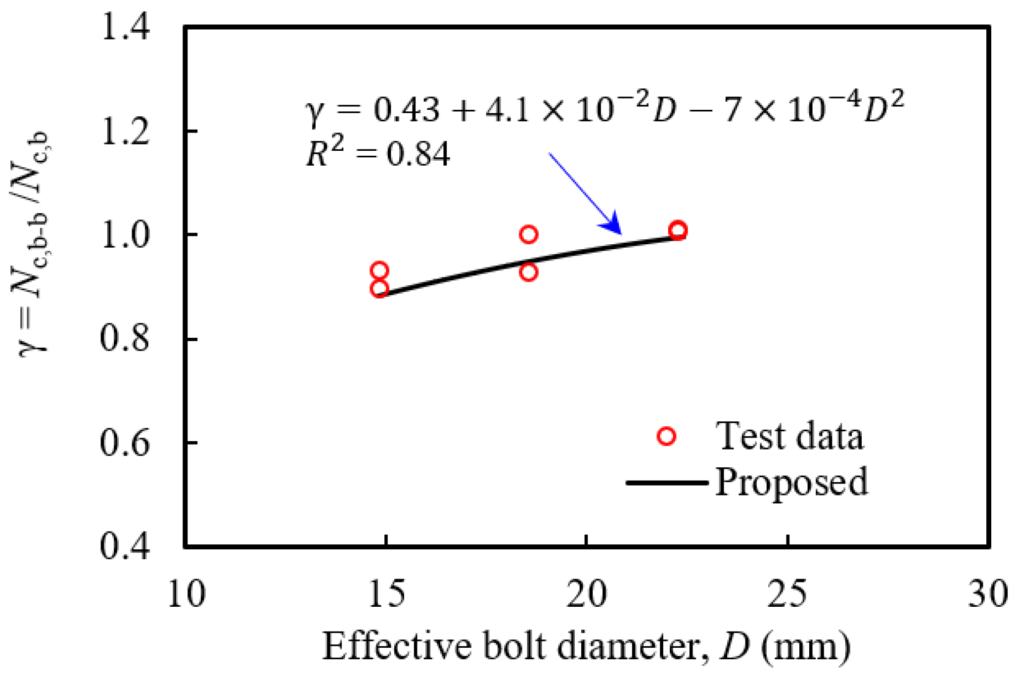
- The predicted ultimate load capacity determined using existing design code AS4100 was very conservative for the bolt-coupler connections when the bolt spacing gap increases. The existing design equation is modified and introduced additional two parameters ( and ) to predict accurately the ultimate strength capacity of bolt-coupler connections under compression. The prediction of ultimate load capacity obtained from the proposed design equation (Equation (6)) shows a better agreement with the test and gives a more accurate and safer prediction for all cases. The proposed design equation can be used by design engineers to determine the design capacity of bolt-coupler connections with a certain bolt spacing gap, which will give more confidence to the design of the prefabricated CFST columns with bolt-coupler connections.
Author Contributions
Funding
Institutional Review Board Statement
Informed Consent Statement
Data Availability Statement
Acknowledgments
Conflicts of Interest
References
- Mao, C.; Shen, Q.; Shen, L.; Tang, L. Comparative study of greenhouse gas emissions between off-site prefabrication and conventional construction methods: Two case studies of residential projects. Energy Build. 2013, 6, 165–176. [Google Scholar] [CrossRef]
- Hassan, M.K.; Sheikh, M.N.; Saha, S. Behaviour, and design of prefabricated CFST stub columns with PCC connections under compression. Thin Walled Struct. 2021, 166, 108041. [Google Scholar] [CrossRef]
- Zhang, X.; Skitmore, M.; Peng, Y. Exploring the challenges to industrialized residential building in China. Habitat Int. 2014, 41, 176–184. [Google Scholar] [CrossRef]
- Hassan, M.K.; Tajhya, S. Numerical investigation of modified splice plate beam-to-beam connections for prefabricated composite structure. Int. J. Eng. Constr. Comput. 2019, 1, 27–35. [Google Scholar]
- Jiang, Y.; Zhao, D.; Wang, D.; Xing, Y. Sustainable performance of buildings through modular refabrication in the construction phase: A comparative study. Sustainability 2019, 11, 5658. [Google Scholar] [CrossRef]
- Hassan, M.K.; Subramanian, K.B.; Saha, S.; Sheikh, M.N. Behaviour of prefabricated steel-concrete composite slabs with a novel interlocking system-Numerical analysis. Eng. Struct. 2021, 245, 112905. [Google Scholar] [CrossRef]
- Han, L.H.; Bjorhovde, R.; Li, W. Developments, and advanced applications of concrete-filled steel tubular (CFST) structures: Members. J. Constr. Steel Res. 2014, 100, 211–228. [Google Scholar] [CrossRef]
- Liu, Y.; Ma, H.; Li, Z.; Wang, W. Seismic behaviour of full-scale prefabricated RC beam-CFST column joints connected by reinforcement coupling sleeves. Structures 2020, 28, 2760–2771. [Google Scholar] [CrossRef]
- Uy, B. Strength of short concrete filled high strength steel box columns. J. Constr. Steel Res. 2001, 57, 113–134. [Google Scholar] [CrossRef]
- Sakino, K.; Nakahara, H.; Morino, S.; Nishiyama, I. Behaviour of centrally loaded concrete-filled steel-tube short columns. J. Struct. Eng. 2004, 130, 180–188. [Google Scholar] [CrossRef]
- Shim, C.S.; Kim, J.H.; Chung, C.H.; Chang, S.P. The behaviour of shear connection in a composite beam with full-depth precast slab. Proc. Inst. Civ. Eng—Struct. Build. 2000, 140, 101–110. [Google Scholar] [CrossRef]
- Ataei, A.; Bradford, M.A.; Valipour, H.R. Experimental study of flush end plate beam-to-CFST column composite joints with deconstructable bolted shear connectors. Eng. Struct. 2015, 99, 616–630. [Google Scholar] [CrossRef]
- Lam, D.; Dai, X.; Ashour, A.; Rehman, N. Recent research on composite beams with demountable shear connectors. Steel Constr. 2017, 10, 125–134. [Google Scholar] [CrossRef]
- Uy, B.; Patel, V.; Li, D.; Aslani, F. Behaviour, and design of connections for demountable steel and composite structures. Structures 2017, 9, 1–12. [Google Scholar] [CrossRef]
- Li, D.; Uy, B.; Patel, V.; Aslani, F. Behaviour, and design of demountable CFST column-column connections subjected to compression. J. Constr. Steel Res. 2018, 141, 262–274. [Google Scholar] [CrossRef]
- Yang, F.; Liu, Y.; Jiang, Z.; Xin, H. Shear performance of a novel demountable steel concrete bolted connector under static pushout tests. Eng. Struct. 2018, 160, 133–146. [Google Scholar] [CrossRef]
- Qing, Y.; Wang, C.L.; Meng, S.; Zeng, B. Experimental study on the seismic performance of precast concrete columns with thread-bolt combination couplers. Eng. Struct. 2022, 251, 113461. [Google Scholar] [CrossRef]
- Kumar, R.; Mandal, P.K.; Narayan, A.; Das, A.J. Evaluation of load transfer mechanism under axial loads in a novel coupler of dual height rock bolts. Int. J. Min. Sci. Technol. 2021, 31, 225–232. [Google Scholar] [CrossRef]
- Kwon, G.; Engelhardt, M.D.; Klingner, R.E. Experimental behaviour of bridge beams retrofitted with post installed shear connectors. J. Bridge Eng. 2011, 16, 536–545. [Google Scholar] [CrossRef]
- Xue, W.; Bai, H.; Dai, L.; Hu, X.; Dubec, M. Seismic behaviour of precast concrete beam-column connections with bolt connectors in columns. Struct. Concr. 2020, 22, 1297–1314. [Google Scholar] [CrossRef]
- Pitrakkos, T.; Tizani, W.; Cabrera, M.; Salh, N.F. Blind bolts with headed anchors under combined tension and shear. J. Constr. Steel Res. 2021, 179, 106546. [Google Scholar] [CrossRef]
- Song, Y.; Wang, J.; Uy, B.; Li, D. Experimental behaviour, and fracture prediction of austenitic stainless-steel bolts under combined tension and shear. J. Constr. Steel Res. 2020, 166, 105916. [Google Scholar] [CrossRef]
- Nijgh, M.P.; Gîrbacea, I.A.; Veljkovic, M. Elastic behaviour of a tapered steel-concrete composite beam optimized for reuse. Eng. Struct. 2019, 183, 366–374. [Google Scholar] [CrossRef]
- Xue, W.; Yang, X.; Hu, X. Full-scale tests of precast concrete beam-column connections with composite T-beams and cast in-place columns subjected to cyclic loading. Struct. Concr. 2019, 21, 169–183. [Google Scholar] [CrossRef]
- Ataei, A.; Bradford, M.A.; Liu, X. Experimental study of composite beams having a precast geopolymer concrete slab and deconstructable bolted shear connectors. Eng. Struct. 2016, 114, 1–13. [Google Scholar] [CrossRef]
- EN 1994-1-1; Eurocode 4: Design of Composite Steel and Concrete Structures, Part 1-1: General Rules and Rules for Buildings. European Standard: London, UK, 2004.
- Yang, F.; Liu, Y.; Xin, H.; Veljkovic, M. Fracture simulation of a demountable steel concrete bolted connector in push-out tests. Eng. Struct. 2021, 239, 112305. [Google Scholar] [CrossRef]
- Ding, B.; Zhao, Y.; Huang, Z.; Cai, L.; Wang, N. Tensile bearing capacity for bolted spherical joints with different screwing depths of high-strength bolts. Eng. Struct. 2020, 225, 111255. [Google Scholar] [CrossRef]
- Zhang, Y.; Chen, B.; Liu, A.; Pi, Y.L.; Zhang, J.; Wang, Y.; Zhong, L. Experimental study on shear behaviour of high strength bolt connection in prefabricated steel-concrete composite beam. Compos. Part B 2019, 159, 481–489. [Google Scholar] [CrossRef]
- Wang, W.; Zhang, X.D.; Zhou, X.L.; Zhang, B.; Chen, J.; Li, C. Experimental study on shear performance of an advanced bolted connection in steel-concrete composite beams. Case Stud. Constr. Mater. 2022, 16, e01037. [Google Scholar] [CrossRef]
- Lee, S.W.; Nestler, A. Simulation-aided design of Thread Milling Cutter. In Proceedings of the 5th CIRP Conference on High Performance Cutting, Zurich, Switzerland, 4–7 June 2012; pp. 120–125. [Google Scholar]
- Hassan, M.K.; Ahmed, B.; Saha, S. Effect of bolt thread on the failure mode and ultimate capacity of bolts under tension and compression. In Proceedings of the 3rd International Conference on Structural Engineering Research, Sydney, Australia, 27–30 November 2022. [Google Scholar]
- AS 4100 1998; Steel Structures. Standards Australia: Sydney, Australia, 2016.


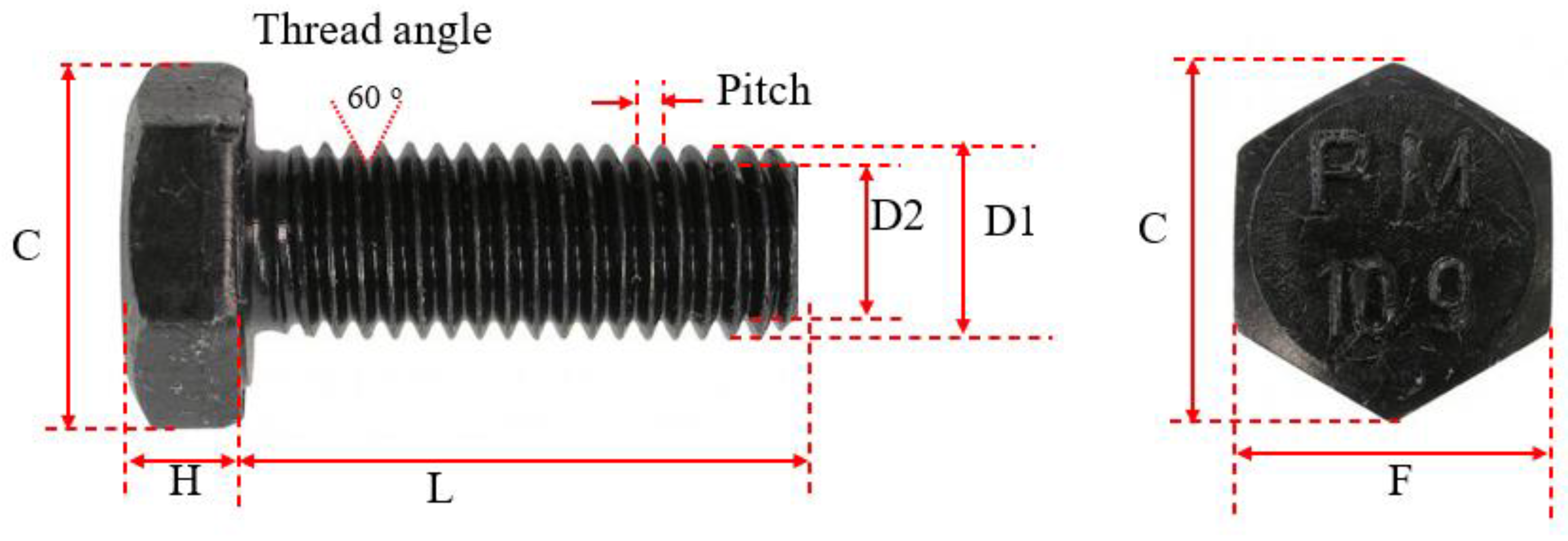
| Bolt Type and Grade | D (mm) | D1 (mm) | D2 (mm) | H (mm) | C (mm) | F (mm) | L (mm) | Pitch, P (mm) | Thread Angle (°) |
|---|---|---|---|---|---|---|---|---|---|
| M16-8.8 | 16 | 15.84 | 13.84 | 10.07 | 27.20 | 23.81 | 60.08 | 2.00 | 60 |
| M16-10.9 | 16 | 15.86 | 13.86 | 10.18 | 27.26 | 23.83 | 59.91 | 2.00 | 60 |
| M20-8.8 | 20 | 19.82 | 17.30 | 12.47 | 34.12 | 29.91 | 60.02 | 2.50 | 60 |
| M20-10.9 | 20 | 19.82 | 17.26 | 12.48 | 34.21 | 29.92 | 60.02 | 2.50 | 60 |
| M24-8.8 | 24 | 23.76 | 20.72 | 15.12 | 40.93 | 35.63 | 59.76 | 3.00 | 60 |
| M24-10.9 | 24 | 23.74 | 20.74 | 15.24 | 40.83 | 35.61 | 59.43 | 3.00 | 60 |
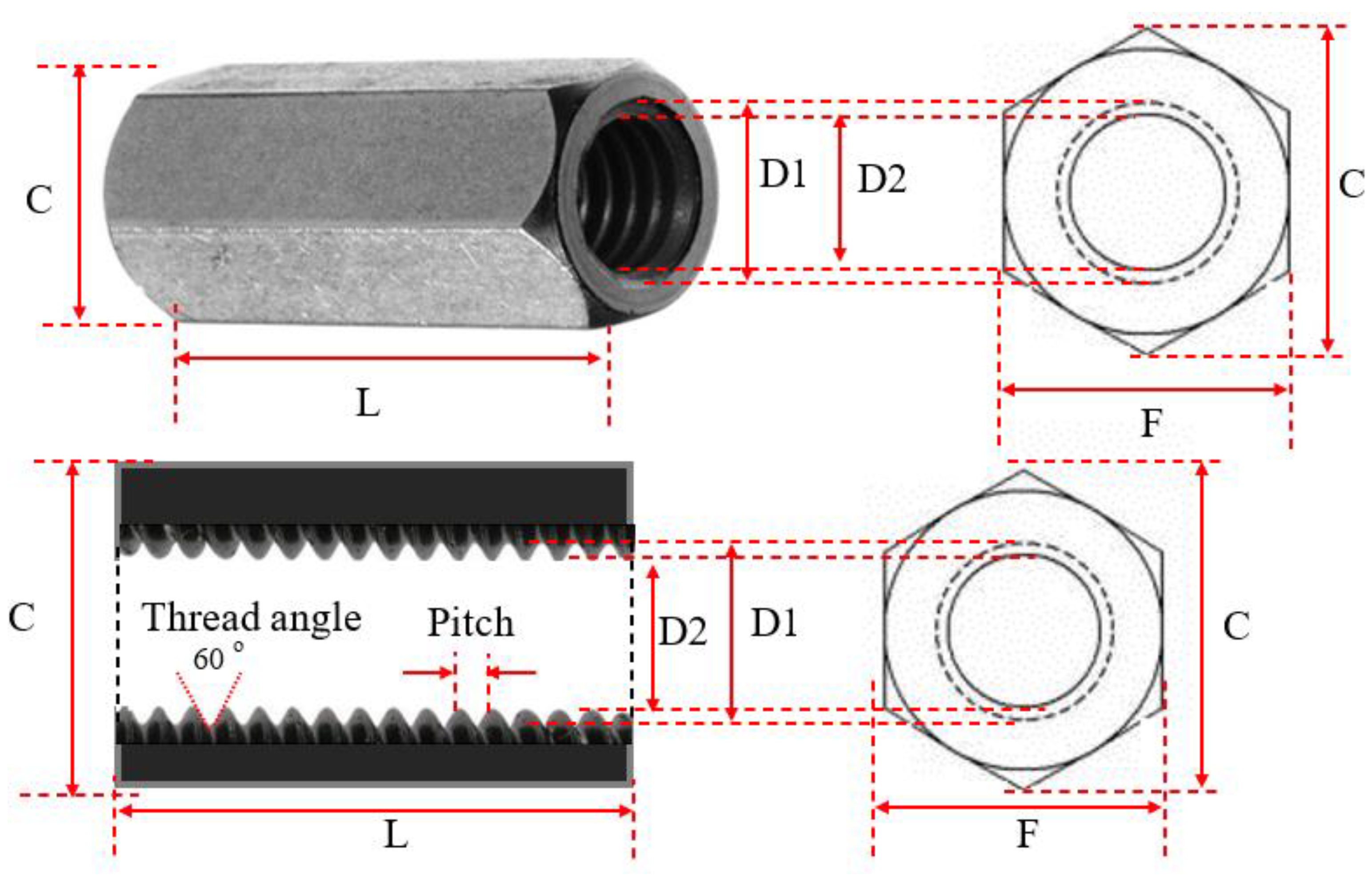
| Coupler Type and Grade | D (mm) | D1 (mm) | D2 (mm) | C (mm) | F (mm) | L (mm) | Pitch (mm) | Thread Angle (°) |
|---|---|---|---|---|---|---|---|---|
| M16-8.8 | 16 | 15.84 | 14.78 | 27.46 | 23.98 | 51.92 | 2.00 | 60 |
| M16-5.6 | 16 | 15.86 | 14.18 | 27.34 | 23.94 | 49.98 | 2.00 | 60 |
| M20-8.8 | 20 | 19.82 | 18.34 | 33.94 | 29.84 | 60.16 | 2.50 | 60 |
| M20-5.6 | 20 | 19.82 | 17.84 | 34.18 | 29.82 | 49.71 | 2.50 | 60 |
| M24-8.8 | 24 | 23.76 | 21.60 | 40.30 | 35.36 | 71.48 | 3.00 | 60 |
| M24-5.6 | 24 | 23.74 | 21.52 | 40.60 | 35.48 | 71.65 | 3.00 | 60 |
| Bolt Type | Bolt Grade | Es (GPa) | Elongation (%) | Proof Load (kN) | ||
|---|---|---|---|---|---|---|
| M16-8.8 | 8.8 | 200 | 744 | 844 | 16.0 | 91 |
| M16-10.9 | 10.9 | 200 | 1017 | 1091 | 12.7 | 130 |
| M20-8.8 | 8.8 | 200 | 737 | 942 | 15.0 | 147 |
| M20-10.9 | 10.9 | 200 | 1022 | 1084 | 12.9 | 203 |
| M24-8.8 | 8.8 | 200 | 714 | 946 | 14.0 | 212 |
| M24-10.9 | 10.9 | 200 | 981 | 1151 | 11.5 | 293 |
| Coupler Grade | Es (GPa) | ||
|---|---|---|---|
| Grade 5.6 | 200 | 430 | 610 |
| Grade 8.8 | 200 | 744 | 844 |
| Test Number | Specimen Label | Bolt Size (mm) | Bolt Grade | Coupler Grade | Spacing (mm) | Nue (kN) | NAS4100 (kN) | Nc (kN) |
|---|---|---|---|---|---|---|---|---|
| 1 | C-16-8.8-0 | 16 | 8.8 | 8.8 | 0 | 131.10 | 132.23 | 129.09 |
| 2 | C-16-8.8-10 | 16 | 8.8 | 8.8 | 10 | 125.60 | 132.23 | 123.87 |
| 3 | C-16-8.8-20 | 16 | 8.8 | 8.8 | 20 | 109.20 | 132.23 | 108.33 |
| 4 | C-16-10.9-0 | 16 | 10.9 | 8.8 | 0 | 166.90 | 170.92 | 166.87 |
| 5 | C-16-10.9-10 | 16 | 10.9 | 8.8 | 10 | 151.80 | 170.92 | 156.86 |
| 6 | C-16-10.9-20 | 16 | 10.9 | 8.8 | 20 | 129.30 | 170.92 | 123.48 |
| 7 | C-20-8.8-0 | 20 | 8.8 | 8.8 | 0 | 236.60 | 230.6 | 241.77 |
| 8 | C-20-8.8-10 | 20 | 8.8 | 8.8 | 10 | 225.40 | 230.6 | 229.68 |
| 9 | C-20-8.8-20 | 20 | 8.8 | 8.8 | 20 | 181.60 | 230.6 | 183.75 |
| 10 | C-20-10.9-0 | 20 | 10.9 | 8.8 | 0 | 297.00 | 265.36 | 278.22 |
| 11 | C-20-10.9-10 | 20 | 10.9 | 8.8 | 10 | 268.30 | 265.36 | 253.18 |
| 12 | C-20-10.9-20 | 20 | 10.9 | 8.8 | 20 | 215.40 | 265.36 | 205.88 |
| 13 | C-24-8.8-0 | 24 | 8.8 | 8.8 | 0 | 401.19 | 333.47 | 366.61 |
| 14 | C-24-8.8-10 | 24 | 8.8 | 8.8 | 10 | 388.75 | 333.47 | 348.28 |
| 15 | C-24-8.8-20 | 24 | 8.8 | 8.8 | 20 | 355.42 | 333.47 | 315.29 |
| 16 | C-24-10.9-0 | 24 | 10.9 | 8.8 | 0 | 471.70 | 405.73 | 446.06 |
| 17 | C-24-10.9-10 | 24 | 10.9 | 8.8 | 10 | 454.84 | 405.73 | 430.44 |
| 18 | C-24-10.9-20 | 24 | 10.9 | 8.8 | 20 | 430.00 | 405.73 | 407.7 |
| 19 | C-24-8.8-5.6-10 | 24 | 8.8 | 5.6 | 10 | 371.68 | 333.47 | 129.09 |
| 20 | C-24-10.9-5.6-10 | 24 | 10.9 | 5.6 | 10 | 382.60 | 333.47 | 123.48 |
| Test Number | Specimen Label | Bolt Size (mm) | Bolt Grade | Coupler Grade | Spacing (mm) | Nue (kN) |
|---|---|---|---|---|---|---|
| 1 | C-16-8.8-0 | 16 | 8.8 | - | - | 140.85 |
| 2 | C-16-8.8-0 | 16 | 8.8 | 8.8 | 0 | 131.10 |
| 3 | C-16-10.9-0 | 16 | 10.9 | - | - | 186.10 |
| 4 | C-16-10.9-0 | 16 | 10.9 | 8.8 | 0 | 166.90 |
| 5 | C-20-8.8-0 | 20 | 8.8 | - | - | 254.97 |
| 6 | C-20-8.8-0 | 20 | 8.8 | 8.8 | 0 | 236.60 |
| 7 | C-20-10.9-0 | 20 | 10.9 | - | - | 294.69 |
| 8 | C-20-10.9-0 | 20 | 10.9 | 8.8 | 0 | 297.00 |
| 9 | C-24-8.8-0 | 24 | 8.8 | - | - | 381.47 |
| 10 | C-24-8.8-0 | 24 | 8.8 | 8.8 | 0 | 401.19 |
| 11 | C-24-10.9-0 | 24 | 10.9 | - | - | 467.94 |
| 12 | C-24-10.9-0 | 24 | 10.9 | 8.8 | 0 | 471.70 |
Publisher’s Note: MDPI stays neutral with regard to jurisdictional claims in published maps and institutional affiliations. |
© 2022 by the authors. Licensee MDPI, Basel, Switzerland. This article is an open access article distributed under the terms and conditions of the Creative Commons Attribution (CC BY) license (https://creativecommons.org/licenses/by/4.0/).
Share and Cite
Hassan, M.K.; Ahmed, B.; Ram, A.; Saha, S. Behaviour and Design of Bolt-Coupler Connections under Compression in Prefabricated CFST Columns. Sustainability 2022, 14, 12166. https://doi.org/10.3390/su141912166
Hassan MK, Ahmed B, Ram A, Saha S. Behaviour and Design of Bolt-Coupler Connections under Compression in Prefabricated CFST Columns. Sustainability. 2022; 14(19):12166. https://doi.org/10.3390/su141912166
Chicago/Turabian StyleHassan, Md Kamrul, Bulbul Ahmed, Anmol Ram, and Swapan Saha. 2022. "Behaviour and Design of Bolt-Coupler Connections under Compression in Prefabricated CFST Columns" Sustainability 14, no. 19: 12166. https://doi.org/10.3390/su141912166
APA StyleHassan, M. K., Ahmed, B., Ram, A., & Saha, S. (2022). Behaviour and Design of Bolt-Coupler Connections under Compression in Prefabricated CFST Columns. Sustainability, 14(19), 12166. https://doi.org/10.3390/su141912166