Article

Robust Decoupling Vector Control of Interior Permanent Magnet Synchronous Motor Used in Electric Vehicles with Reduced Parameter Mismatch Impacts

School of Physics and Electronics Electrical Engineering, Huaiyin Normal University, Huai’an 223309, China
*
Author to whom correspondence should be addressed.
Sustainability 2022, 14(19), 11910; https://doi.org/10.3390/su141911910
Submission received: 26 August 2022 / Revised: 12 September 2022 / Accepted: 18 September 2022 / Published: 21 September 2022

Abstract

:
Interior permanent magnet synchronous motor (IPMSM) drives have been widely employed in sustainable transport such as electric vehicles (EV). However, the traditional vector control (VC) strategies cannot achieve optimal control due to the intrinsic property of the IPMSMs, which is strong coupling. To solve the issue, this paper proposes an improved decoupling VC strategy to improve the steady-state performance of the IPMSMs with reduced parameter mismatch impacts. First, a deviation decoupling strategy is developed, and meanwhile, the parameters that influence the decoupling method are clearly illustrated. This enriches the theory concerning decoupling control and lays the ground for the development of effective solutions to the parameter mismatch issue. Second, the Luenberger observer theory is discussed, based on which the reason why the Luenberger inductance observers are not widely employed is explained for the first time. Third, with the aid of intermediate variables, which are the disturbances caused by the mismatched inductances, a new inductance identification method based on the Luenberger observer is proposed. Finally, the simulation and experimental results prove that the proposed decoupling methods, as well as the parameter identification method, are effective.

1. Introduction

For the sake of sustainability, environmental friendliness, energy conservation, etc., electric vehicles (EV) have become one of the most crucial forms of transportation at present [1,2]. In addition, because the EVs have the typical advantages of easy driving, reduced noise, low maintenance, high safety, and low cost, an increasing number of drivers are obsessed with them [3,4,5]. As the key component of an EV, the traction system plays a dominant role in improving the response speed, stable operation, and working efficiency of the vehicle, and so, it has attracted much attention from both manufacturers and scholars [6]. Considering that interior permanent magnet synchronous motors (IPMSM) have the advantages of high torque density, high energy efficiency, and strong controllability, they are widely adopted in the application of EV traction [7,8,9,10], and the typical vehicle products include the Tesla Model 3, the Porsche Taycan, the Toyota Prius, etc.
In practice, EVs place great demand on the performance of the IPMSM drives. Specifically, when a car starts and overtakes, the motor should show high dynamics, but when the car works in a cruise control state, the motor is required to rotate stably at a certain speed [11]. On this basis, high-performance control strategies which have both good dynamics and steady-state performance are highly desired. The commonly used IPMSM control methods include vector control (VC) and direct torque control (DTC) [12,13]. Traditional VC has both speed and current regulation loops, endowing the motor with satisfying steady-state performance. However, as for the DTC, it discards the speed control loop and directly regulates the output torque of the motor by converting acceleration/deceleration signals from drivers to torque reference. In comparison with the DTC, the VC is characterized by better steady-state performance, but it does not significantly sacrifice the dynamics once the parameters of the PI regulators are well-designed; it is therefore deserving of much more investigation [14].
Based on the automatic control principle, the reasons why the traditional VC does not have dynamics as good as those of the DTC (but has better steady-state performance) include the fact that the dual-loop structure, with at least three PI regulators incorporated, lowers the bandwidth of the system [15]. Low bandwidth brings about larger delay but can reject the impacts of high-frequency noises and disturbances. There are two practical challenges when designing a high-performance VC strategy. First, it is necessary to tune the parameters of the speed and current PI regulators approximately [16]. Nevertheless, the IPMSM is well known for its nonlinear properties. In this case, the system cannot be described as a standard transform function, making it difficult to obtain the optimal parameters of the PI regulators. Second, due to the intrinsic property of the IPMSMs, that is, strong coupling, the d- and q-axis currents are not controlled by the corresponding manipulated voltages. Instead, they are interactively influenced, resulting in static errors and declined dynamics [16]. From the perspectives of these two aspects, decoupling strategies that can linearize the system and remove the coupling effect are highly desired practically [17]. However, the decoupling strategies are usually parameter-dependent, leading to the fact that once mismatched parameters are utilized, static current errors will occur, degrading the steady-state performance remarkably. Hence, it is valuable to develop effective strategies to solve the parameter mismatch issue for the decoupling techniques.
To reduce parameter mismatch impacts on the decoupling VC strategies, two kinds of solutions would be useful: online parameter identification and disturbance rejection [18,19,20,21,22,23,24,25,26,27,28]. (1) Online parameter identification: The common online parameter identification strategies can be categorized as the model reference adaptive system (MRAS) [18], the recursive least square (RLS) method [19], the extended Kalman filter (EKF) [20], state observers [21], and the artificial intelligence (AI) method [22,23]. In terms of these techniques, because the state-observer-based ones are easy to implement and understand, they are attracting increasing attention now. For instance, a series of sliding mode (SM) observers are proposed in [24] to detect the stator inductances, and [25] develops a reduced-order observer to estimate the time constant. (2) Disturbance rejection: In [26,27,28], the current errors caused by parameter mismatch are regarded as disturbances. By the use of observers and disturbance regulators, the disturbances can be observed first and then compensated through feedback compensation. Comparatively speaking, the first method is a direct solution to the parameter mismatch problem, while the latter is a non-direct strategy with a more complicated structure. Overall, the online parameter identification methods based on state observers deserve in-depth investigation, but they are seldom focused on in the field of the decoupling control of IPMSMs.
The Luenberger observer is a method proposed by Luenberger, Kalman, and Bucy which was originally targeted at improving the control rate of a system [29]. It has the advantages of fast response speed, relatively high robustness against external disturbances, and strong capacity for handling nonlinearity; therefore, it has been widely employed for state estimation [30,31,32]. For example, in [30], the PMSM rotor speed and position are detected by a nonlinear Luenberger observer. However, it needs to be mentioned that the previous studies mostly utilized the Luenberger observers to identify the state variables (e.g., position, speed, etc.) of the motor but few focus on parameter (e.g., inductance, resistance, etc.) identification. So far, no studies exactly point out this issue and explain why this happens or mention developing effective Luenberger parameter observers.
This paper presents an improved decoupling VC method to enhance the performance (especially the steady-state performance) of IPMSMs used in EVs. To reduce parameter mismatch impacts on the decoupling VC strategy, a novel inductance identification technique based on the Luenberger disturbance observer is innovatively proposed. The main contributions and novelties can be summarized as follows:
(1)
A deviation decoupling scheme is designed to linearize and decouple the IPMSM model, with the parameter mismatch impacts on its current performance analyzed. This reveals the parameters that influence the control performance of the decoupling VC and addresses the necessity of employing effective parameter identification strategies to solve the issue. Undoubtedly, the theories concerning decoupling control can be enriched through this study.
(2)
Targeting the parameters that are prone to become mismatched and have severe impacts on the control performance, a parameter identification method based on the Luenberger disturbance observer is proposed, with its stability analyzed. It needs to be mentioned that this observer-based online parameter identification method treats the disturbances caused by the mismatched parameters as intermediate variables. It is achieved by discovering the relationship between the parameters and the disturbances, which has seldom been investigated before.
(3)
The reason why the Luenberger observers are not broadly used for parameter identification is explained after introducing the basic theory concerning the observer in this paper for the first time.
The structure of the rest of the paper is as follows. Section 2 presents the deviation decoupling strategy and the impacts of the parameter mismatch on it. In Section 3, the parameter identification method based on the Luenberger disturbance observer is designed. The simulation and experimental results are given in Section 4. Section 5 is the conclusion.

2. Analysis of Deviation Decoupling VC Strategy

The structure of the deviation decoupling VC strategy is illustrated in Figure 1. Compared to the conventional VC in [12], one main difference is reflected in the decoupling part. This part mainly introduces the design method of the decoupling strategy first, and then, the impacts of the parameter mismatch on the decoupling VC are discussed clearly.

2.1. Deviation Decoupling VC Strategy

The electrical properties of the IPMSM in Figure 1 can be described by the following differential equations in the rotating coordinate frame (d, q-axis), where the iron saturation, eddy current, and hysteresis loss are ignored [33]:
{ d i d d t = R s L d i d + L q L d p ω m i q + u d L d d i q d t = L d L q p ω m i d R s L q i q + u q L q ψ f L q p ω m
where id, iq are stator dq-axis currents; ud, uq are dq-axis control voltage; Ld, Lq are real dq-axis inductances; Rs is real stator winding resistance; ωm represents rotor speed; p is the number of pole pairs; ψf is real flux linkage generated by permanent magnets; and t is time. For the sake of intuitiveness, Figure 2a depicts the s-domain model of the motor with the current regulation process considered, where G1 and G2 are the d- and q-axis automatic current regulators (ACR), respectively, and s is the s-domain symbol. It can be noted that the d-axis current is not only related to the d-axis variables but also to the q-axis current, and this applies to the q-axis current as well. This is the so-called coupling. In practice, ud and uq cannot control the d- and q-axis currents independently. Concretely, when regulating the d-axis current using an ACR, iq would influence ud and further id, but when id is regulated, uq and iq will be influenced simultaneously. This results in a longer settling time and static current errors, and even worse, the system stability is inclined to decline. To improve motor control performance, it is significant to develop effective decoupling techniques.
As shown in Figure 2b, a deviation coupling method with three modules G3, G4, and G5 is adopted for decoupling. Concerning the decoupling strategy, three aspects should be addressed. First, considering that the decoupling component is implemented in the digital processor, which will be combined with the original IPMSM model into the decoupled one, the delay effect of the inverter needs to be ignored, and it is equivalent to a scaling module. Second, G5 is incorporated into the q-axis property to eliminate the impacts of motional back electromotive force (EMF); so, it can be described as:
G 5 = p ω m ψ f
Third, the purpose of using G3 and G4 is to convert the original machine model to the form of (3).
{ u d = 1 L d s + R s i d u q = 1 L q s + R s i q { u d = L d d i d d t + i d R s u q = L q d i q d t + i q R s
where ud’ and uq’ are the manipulated voltages after decoupling. The main challenge of the proposed decoupling method is how to design G3 and G4.
In Figure 2b, ud and uq can be represented by:
{ u d = G 1 ( i d _ r e f i d ) u d + G 4 ( i q _ r e f i q ) u q = G 2 ( i q _ r e f i q ) u q + G 3 ( i d _ r e f i d ) + p ω m ψ f
Substitute (4) into (1), and it can be further derived that:
{ u d + G 4 ( i q _ r e f i q ) + p ω m L q i q = L d d i d d t + i d R s u q + G 3 ( i d _ r e f i d ) p ω m L d i d = L q d i q d t + i q R s
Then, to make (5) consistent with (3), G3 and G4 should satisfy the following condition:
{ G 4 ( i q _ r e f i q ) + p ω m L q i q = 0 G 3 ( i d _ r e f i d ) p ω m L d i d = 0 { G 3 = p ω m L d i d i d _ r e f i d G 4 = p ω m L q i q i q _ r e f i q
By using (6), the IPMSM can be decoupled completely in the d, q-axis reference frame; the manipulated voltages ud’ and uq’ generated by the d- and q-axis ACRs, respectively, can regulate the corresponding currents independently. In theory, this contributes to improving both the dynamics and the stability of the VC strategy [34].

2.2. Parameter Mismatch Impacts on Decoupling VC Strategy

Based on the above analysis, the decoupling strategy is directly related to Ld, Lq, and ψf. In practice, these parameters are measured by using offline methods [35]. However, different parameter values might be obtained once the test instruments and tester are changed; so, it is possible that the offline parameters would mismatch with the real ones.
Denote the measured d-axis inductance, q-axis inductance, and flux linkage as Ld_m, Lq_m and ψf_m, respectively. Then, when using the proposed decoupling strategy, ud and uq in Figure 2b are:
{ u d = u d p ω m L q _ m i q u q = u q + p ω m L d _ m i d + p ω m ψ f _ m
When substituting (7) into (1), the machine model after decoupling is:
{ u d = L d d i d d t + i d R s + p ( L q _ m L q ) ω m i q u q = L q d i q d t + i q R s p ( L d _ m L d ) ω m i d p ( ψ f _ m ψ f ) ω m
By comparing (8) with (3), the goal of decoupling cannot be achieved once the parameter mismatch issue occurs, degrading the system performance. To discuss the parameter mismatch impacts on the steady-state performance (static errors), simplify (8) as:
{ u d = i d R s + p ( L q _ m L q ) ω m i q u q = i q R s p ( L d _ m L d ) ω m i d p ( ψ f _ m ψ f ) ω m
Then, id and iq can be obtained by solving the equations in (9):
{ i d = R s u d p 2 ( L q _ m L q ) ( ψ f _ m ψ f ) ω m 2 p ( L q _ m L q ) ω m u q R s 2 + p 2 ( L q _ m L q ) ( L d _ m L d ) ω m 2 i q = R s u q + R s p ( ψ f _ m ψ f ) + p ( L d _ m L d ) ω m u d R s 2 + p 2 ( L q _ m L q ) ( L d _ m L d ) ω m 2
The static current errors ∆id and ∆iq corresponding to certain ud’ and uq’ can be calculated by:
{ Δ i d = R s u d p 2 ( L q _ m L q ) ( ψ f _ m ψ f ) ω m 2 p ( L q _ m L q ) ω m u q R s 2 + p 2 ( L q _ m L q ) ( L d _ m L d ) ω m 2 u d R s Δ i q = R s u q + R s p ( ψ f _ m ψ f ) + p ( L d _ m L d ) ω m u d R s 2 + p 2 ( L q _ m L q ) ( L d _ m L d ) ω m 2 u q R s
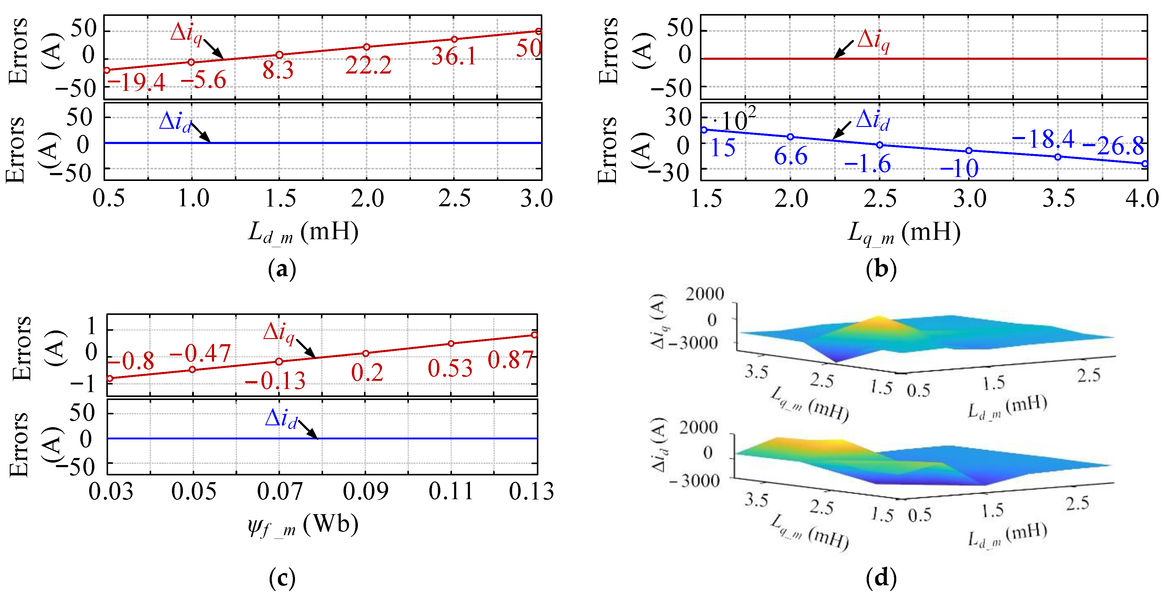
For the sake of intuitiveness, taking an IPMSM prototype, of which the real parameters are shown in Table 1 as an example, Figure 3 illustrates the relationship between the static current errors and the measured parameters (at the rated speed) when the manipulated voltages satisfy the following extreme conditions:
u d = 1 , u q = 0.9 U d c
where Udc is the bus voltage. From Figure 3, three interesting phenomena can be found. First, as shown in Figure 3a, when only the d-axis inductance mismatches, the magnitudes of the static d-axis current errors increase linearly as the inductance deviations increase, but the q-axis current errors remain zero. Figure 3b shows the similar phenomenon. Second, because the given d-axis manipulated voltage is much lower than the q-axis one, the static error magnitudes in Figure 3b are much smaller in comparison with those in Figure 3c. This represents the fact that when the voltage is higher, the parameter mismatch impacts become clearer. Third, when only the flux linkage mismatches, both the d- and q-axis current errors stand at low positions. In particular, the d-axis one is zero. This means that the flux linkage mismatch has weak impacts on the control performance. Overall, the d- and q-axis inductances have more severe impacts on the proposed decoupling control method; so, they need to be detected online.

3. Proposed Luenberger Disturbance Observer-Based Inductance Identification

As explained in Section 2, inductance mismatch has remarkable impacts on the steady-state performance of the proposed deviation decoupling VC strategy. To solve the issue, this part develops a Luenberger disturbance observer-based inductance identification method to estimate the real-time parameter values after briefly introducing the basic theory concerning the Luenberger observer and the reason why the Luenberger inductance observers are not available.

3.1. Introduction of Luenberger Observer Theory

The Luenberger observer is a model-based method, and usually, the state space model of a system is a prerequisite for constructing the observer. It regards the errors between the observed and the measured state variables as the feedback. When the observer becomes stable, the feedback errors are expected to reach zero, ensuring that the observed state variables can equal the real values. It deserves to be mentioned that when the feedback errors become zero, the variables that need to be detected can be obtained.
When designing a Luenberger observer, two stages should be included. First, select the measured states and the to-be-detected states as the global variables, and construct a standard system, which is described as:
{ d x d t = A x + B u + D y = C x
where x represents the global variables, and y is the output state variables of the system. A, B, C, and D are the coefficient matrixes. u is the manipulated variable. Second, based on the feedback control theory, use a feedback matrix H to introduce the feedback errors between the observed and real states into the state space equations, and the Luenberger observer can be constructed as:
{ d x * d t = A x * + B u + D + H ( y * y ) y * = C x *
where x* is the observed states, and y* is the observed output state variables. Finally, as long as H can be designed appropriately, making y* = y, (14) will show the same properties as the real system. Then, the variable/parameter values obtained from the observer will equal the real ones.
Based on the abovementioned theory concerning the Luenberger observer, if directly constructing inductance observers, apart from id and iq, Ld and Lq should be selected as the global variables, namely x = [id, iq, Ld, Lq]T. However, from the machine model (1), it can be noticed that the d-axis and q-axis inductance information is contained in the same terms, Ldmiq/Ld and Ldmid/Lq, leading to the fact that a standard system in the form of (13) cannot be established. This is the reason why there are no Luenberger inductance observers now. Therefore, in order to use the Luenberger observer theory to detect the inductances, intermediate variables must be employed. In this paper, a disturbance observer-based inductance identification strategy (disturbances are treated as the intermediate variables) is developed and is detailed in Section 3.2.

3.2. Inductance Identification Based on Luenberger Disturbance Observer

3.2.1. Relationship between Inductances and Disturbances

If the inductance mismatch issue appears, the real d- and q-axis inductances Ld, Lq can be described as:
{ L d = L d _ m + Δ L d L q = L q _ m + Δ L q
where ∆Ld and ∆Lq are the d- and q-axis inductance errors, respectively. Substitute (15) into (1), and it can be derived that:
{ d i d d t = R s L d _ m i d + L q _ m L d _ m p ω m i q + u d L d _ m + Δ L q L d _ m p ω m i q Δ L d L d _ m d i d d t d i q d t = L d _ m L q _ m p ω m i d R s L q _ m i q + u q L q _ m ψ f L q _ m p ω m Δ L d L q _ m p ω m i d Δ L q L q _ m d i q d t
Denote the d- and q-axis disturbances (fd, fq) caused by inductance mismatch as:
{ f d = Δ L q L d _ m p ω m i q Δ L d L d _ m d i d d t f q = Δ L d L q _ m p ω m i d Δ L q L q _ m d i q d t
It needs to be mentioned that fd and fq are the disturbances when using the measured inductances to establish the machine model. Considering that our purpose is to identify the inductances under the stable states, (17) can be further simplified as:
{ f d = Δ L q L d _ m p ω m i q f q = Δ L d L q _ m p ω m i d { Δ L q = L d _ m f d p ω m i q Δ L d = L q _ m f q p ω m i d
Equation (17) shows that when the motor rotates stably, there are certain relationship between the inductance errors and the disturbances. Practically, as long as the disturbances can be observed by a Luenberger observer, ∆Ld and ∆Lq can be calculated by using (18). Then, the relationship between the real-time d- and q-axis inductances and the disturbances can be obtained as:
{ L d = L d _ m L q _ m f q p ω m i d L q = L q _ m + L d _ m f d p ω m i q

3.2.2. Luenberger Disturbance Observer

Based on (19), it is feasible to calculate the real-time inductances once the disturbances are obtained at first. Now, the prerequisite of inductance identification becomes disturbance estimation. This part presents the Luenberger disturbance observer design process, after which the inductance identification technique is developed.
(a)
Design of observer
First, to observe the d- and q-axis disturbances, id, iq, fd, and fq need to be selected as global variables and x = [id, iq, fd, fq]T. Meanwhile, define the output state variables of the system as y = [id, iq, id, iq]T and u = [ud, uq, 0, 0]T. Then, assume that the change rate of fd and fq is small enough to be ignored [36], and when constructing the standard system in the form of (13), the coefficient matrixes are as follows:
A = [ R s L d _ m L q _ m L d _ m p ω m 1 0 L q _ m L d _ m p ω m R s L d _ m 0 1 0 0 1 0 0 0 0 1 ] , B = [ 1 L d _ m 0 0 0 0 1 L d _ m 0 0 0 0 0 0 0 0 0 0 ] , C = [ 1 0 0 0 0 1 0 0 1 0 0 0 0 1 0 0 ] , D = [ 0 p ω m ψ f L q _ m 0 0 ]
Second, construct the Luenberger disturbance observer (see Figure 4) in the form of (14), in which the observed states are as follows:
x * = [ i d * , i q * , f d * , f q * ] T , y * = [ i d * , i q * , i d * , i q * ] T
When the system reaches the equilibrium state, the estimated currents equal the real ones, that is, id* = id and iq* = iq. At the moment, fd* and fq* represent the real disturbances. In terms of the feedback matrix H, because there are four feedback variables, it can be defined as:
H = [ h 1 0 0 0 0 h 2 0 0 0 0 h 3 0 0 0 0 h 4 ]
where h1, h2, h3, and h4 are constants that need to be adjusted to make the observer stable.
  • (b) Stability analysis
As shown in Figure 4, the proposed d- and q-axis disturbance observers are independent. Hence, stability analysis should be applied to them one by one. Considering that the stability analysis process is similar for both observers, this paper only takes the d-axis one as an example for analysis.
When it comes to the d-axis disturbance observer, the global variables are x = [id, fd]T, x* = [id*, fd*]T, y = [id, id]T, y* = [id*, id*]T, and u = [ud, 0]T. Then, the coefficient matrixes are:
A = [ R s L d _ m 1 0 1 ] , B = [ 1 L d _ m 0 0 0 ] , C = [ 1 0 1 0 ] , H = [ h 1 0 0 h 3 ]
According to the automatic control theory, to make a Luenberger observer stable the feedback coefficients need to be placed based on the expected poles [37]. Assuming that the expected poles of the observer are p1 and p2, the conditions that ensure the system to be stable are as follows:
E i g ( A - H C ) = { p 1 , p 2 }
where Eig ( ) is the function to calculate the eigenvalues of a matrix. Denote E and γ as the identity matrix and the eigenvalue, respectively. γE–(AHC) can be derived as:
γ I ( A- H C ) = [ γ + R s L d _ m + h 1 1 h 3 γ ]
Then, the determinant of (25) can be calculated by:
det ( γ I ( A- H C ) ) = γ 2 + ( R s L d _ m + h 1 ) γ + h 3
Considering that the expected determinants of (25) equal p1 and p2, it can be derived that:
( γ p 1 ) ( γ p 2 ) = γ 2 ( p 1 + p 2 ) γ + p 1 p 2
By comparing (26) and (27), to make the observer stable the following conditions should be satisfied:
h 1 = ( p 1 + p 2 ) R s L d _ m , h 3 = p 1 p 2
In practice, the feedback coefficients can be obtained by using (28). In addition, when the observer becomes stable the disturbances fd* (as well as fq*) can be directly calculated.

3.2.3. Inductance Calculation

After estimating the disturbances fd* and fq*, substitute them into (19) and the d- and q-axis inductances can be calculated by:
{ L d * = L d _ m L q _ m f q * p ω m i d L q * = L q _ m + L d _ m f d * p ω m i q
where Ld* and Lq* are the estimated d- and q-axis inductances, respectively. Furthermore, the estimated inductances can be applied to the decoupling component in Figure 1, improving the steady-state performance of the system.

4. Verification Results

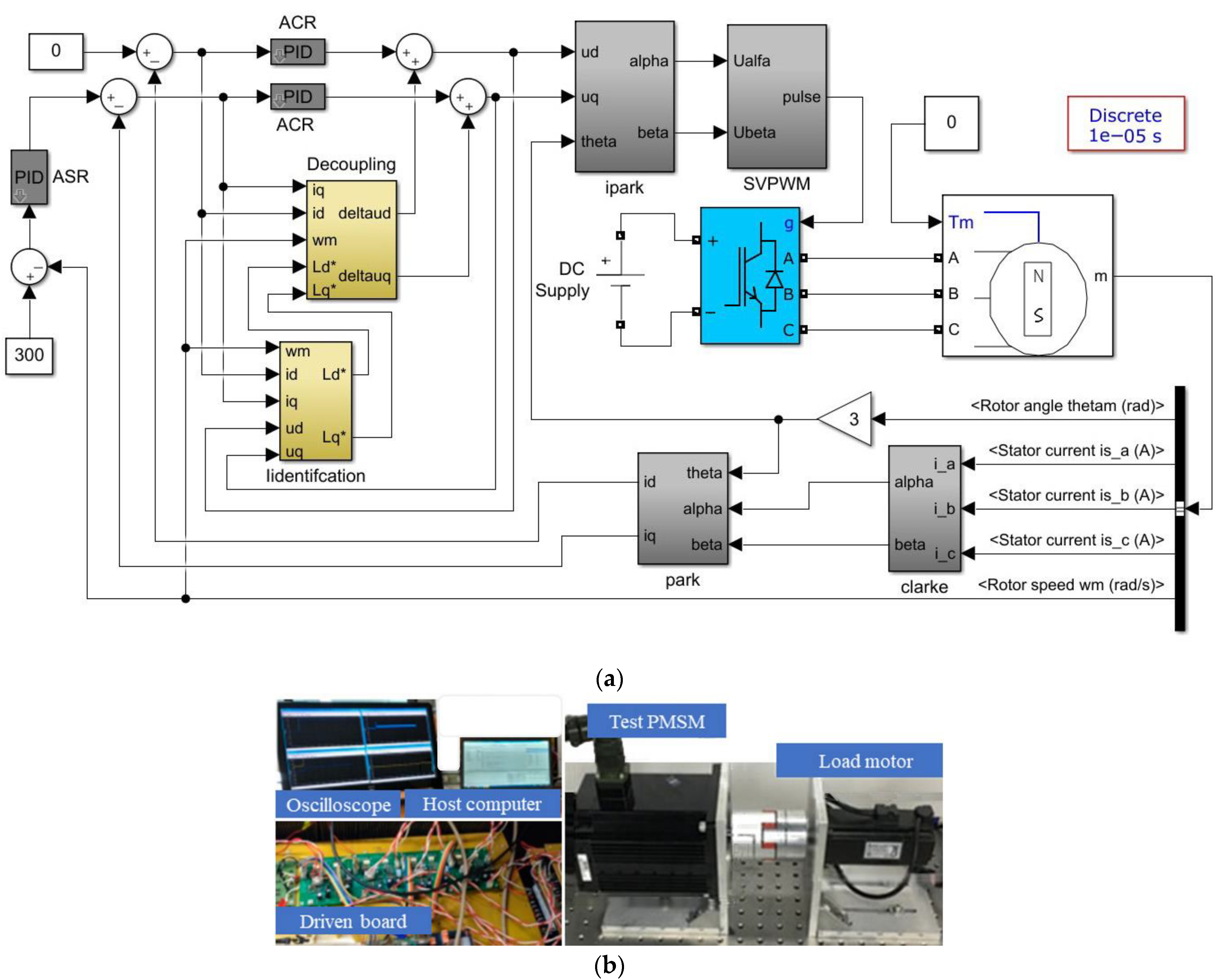
To verify the proposed decoupling VC and inductance identification strategies, the simulation and experiments are conducted on a three-phase IPMSM, of which the parameters comply with Table 1. The simulation system that is consistent with Figure 1 is established in MATLAB/Simulink 2018b and is shown in Figure 5a, and the experimental test bench is shown in Figure 5b. During simulation, a fixed-step mode is employed, and the calculation period is 1.0e−5 s, while the switching period of the power transistors is 0.1 ms. In terms of the experimental devices, insulated gate bipolar transistor (IGBT) devices are adopted to constitute the inverter, of which switching frequency is 10.0 kHz. DSP TMS320F28335 serves as the digital processor, and the control algorithms are executed on it. An induction motor is coupled to the test machine, providing load torque. The state information, such as currents and voltages, can be transmitted to the host computer, which can further record the data for analysis.

4.1. Simulation Results

The purposes of simulation require that first the control performances before and after using the proposed decoupling strategy need to be compared, proving that the decoupling method is able to improve the system control performance. Second, when the inductance mismatch issue occurs, the steady-state performances before and after the inductance identification method is applied to the decoupling control process should be compared, verifying that the proposed parameter identification method is effective.
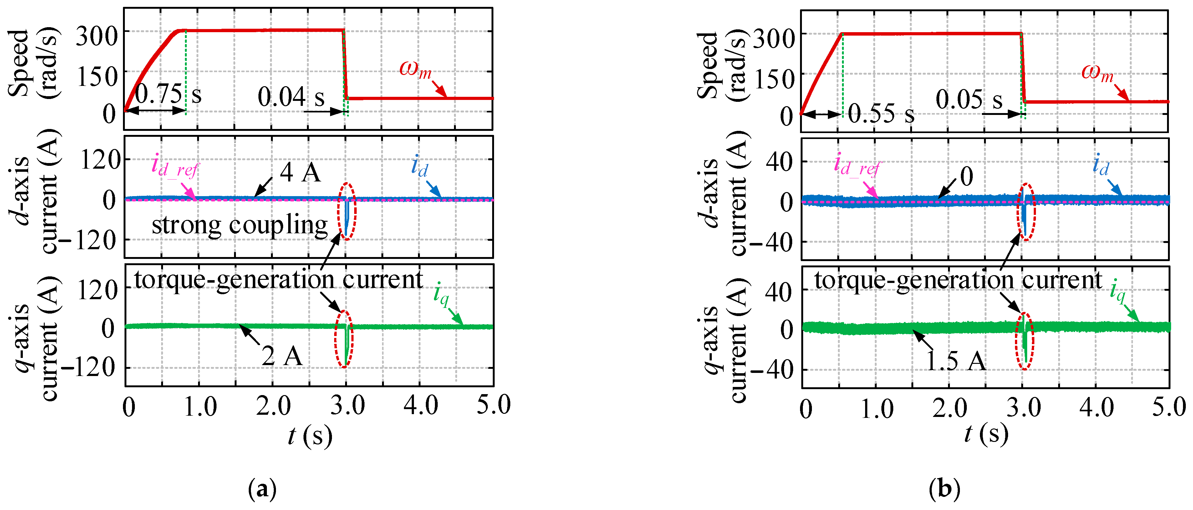
Figure 6a shows the speed and current performance without using the decoupling strategy, and Figure 6b shows the system performance of the proposed decoupling VC method (without parameter mismatch). The simulation setups are as follows. Between 0 and 2.0 s, the motor speeds up to 300 rad/s (high speed) under 4.5 Nm. Then, the motor speed levels off until 3.0 s when the rotor speed decreases at 50 rad/s (low speed). For the sake of analytical simplicity, during simulation the d-axis current reference is set as zero, and there is no current limit when the motor speeds down. Four interesting phenomena can be seen. First, the settling time during acceleration is 0.75 s without decoupling, but it becomes 0.55 s after the decoupling strategy is adopted. This proves that the coupling effects influence the system dynamics. Second, the settling time during deceleration in Figure 6a,b is similar (0.04 s and 0.06 s, respectively), illustrating that the proposed decoupling strategy does not sacrifice the system dynamics remarkably. Third, when the motor runs stably, the d-axis current cannot track the reference value accurately, but this issue is solved after using the decoupling method. Undoubtedly, the proposed decoupling strategy can improve the steady-state performance. Finally, when the motor speed declines at 3.0 s, the magnitudes of the d- and q-axis currents are larger in Figure 6a in comparison with those in Figure 6b. Comparatively speaking, in addition to the currents used for the torque generation (both the d- and the q-axis currents contribute to the electromagnetic torque generation for IPMSMs), without decoupling techniques larger currents can be generated by the strong coupling effects. Overall, the coupling effects influence both the dynamics and the steady-state performance of the IPMSM, and the proposed decoupling strategy is able to improve the system performance.
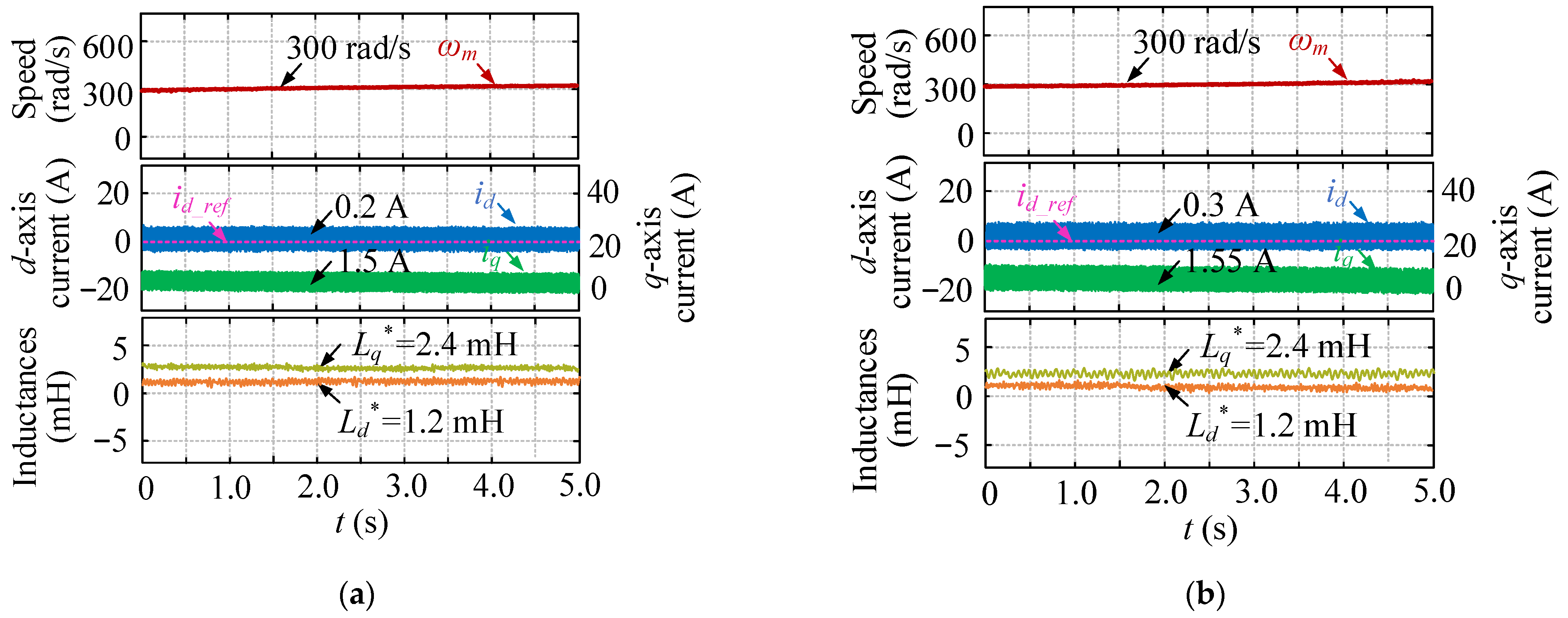
Figure 7 shows the control performance of the proposed decoupling VC method with the inductance mismatch, while Figure 8 depicts the corresponding system performance after the proposed inductance identification method based on the Luenberger disturbance observer is utilized. The simulation setups are as follows. The speed reference is set as the rated value constantly before 0 and 5.0 s, and the d-axis current is controlled to be maintained at zero. It can be noticed that first, regardless of the inductance mismatch, the motor speed can stabilize at the desired level, which benefits from the automatic speed regulator (ASR). Secondly, when the inductances used for decoupling the VC are mismatched, both the d- and the q-axis currents increase, and this is unwanted. Comparatively, after employing the proposed inductance identification method, the d-axis current can nearly track the reference value, while the q-axis one sees a decreasing trend; these are similar to those in Figure 6b. In addition, Figure 8b shows that the estimated inductances are pretty accurate. These prove that the proposed inductance identification strategy based on the Luenberger disturbance observer is effective, and meanwhile, it can be used to enhance the robustness of the decoupling VC strategy.
Overall, the simulation results demonstrate that the proposed decoupling VC can ensure a high system performance. In addition, with the proposed inductance identification technique incorporated, the decoupling strategy is strongly robust against parameter mismatch. Hence, they are valuable in real applications.

4.2. Experimental Results

The experiment was carried out to verify the effectiveness of the proposed decoupling VC strategy and the proposed inductance identification strategy. It deserves to be mentioned that the inductances and resistance in Table 1 are pretty accurate because they are measured by different engineers using different instruments, including an ohmic meter and an inductance meter. Hence, in practice, it is reasonable to treat them as the real parameters of the motor. In this part, the experiment is divided into two parts: dynamic analysis and steady-state performance analysis.
(a)
Dynamic performance analysis
Figure 9 illustrates the dynamic performance of the system when the proposed decoupling strategy is adopted. First, the settling time is about 0.5 s, which is similar to the simulation results. In addition, no speed overshoot can be seen because the PI parameters are well-tuned. Overall, the motor shows good dynamics.
(b)
Steady-state performance analysis
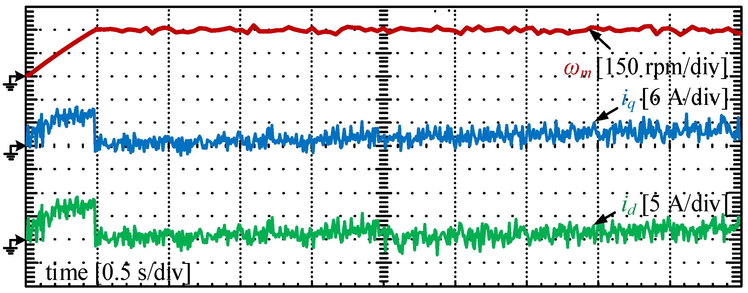
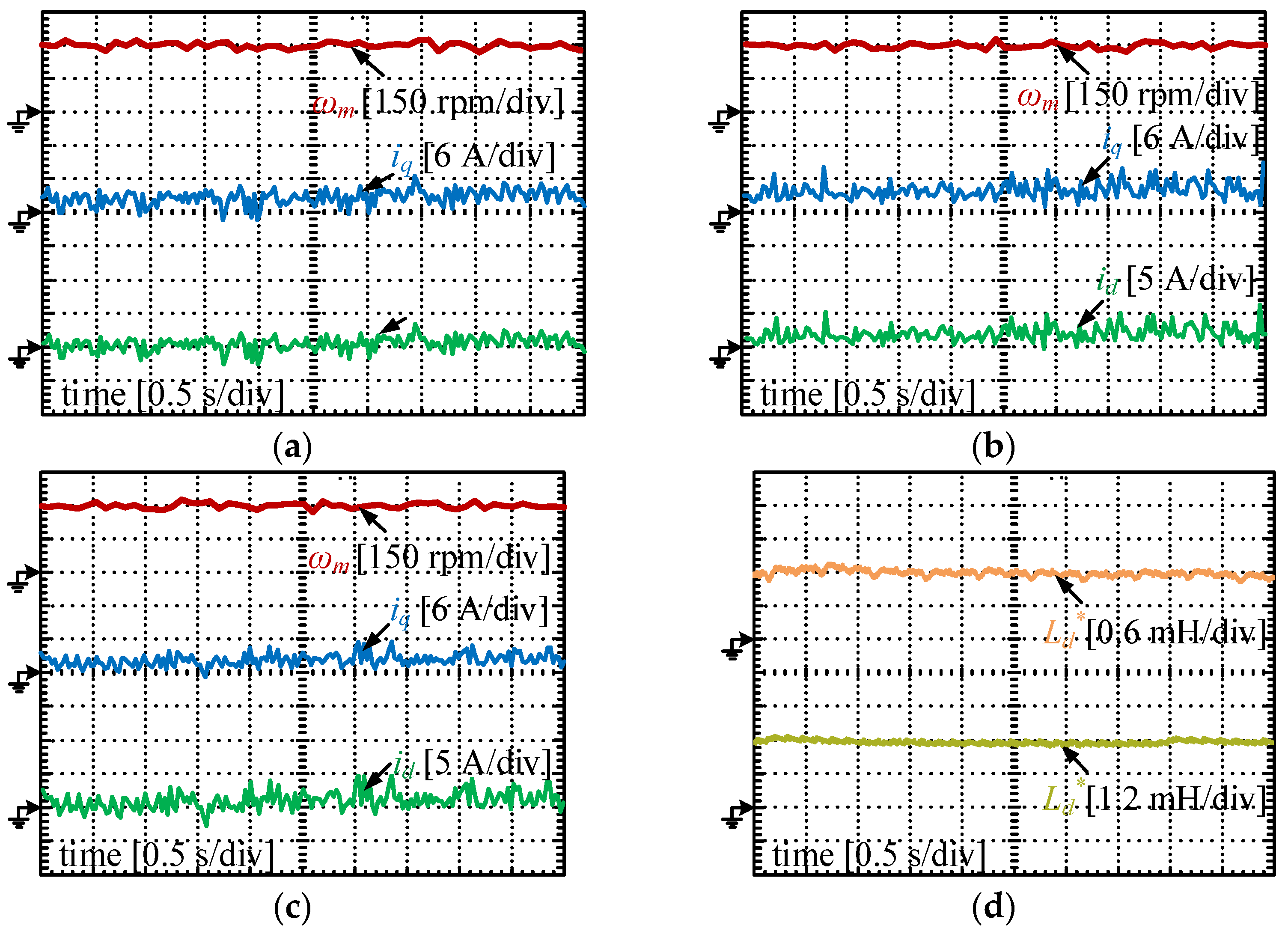
First of all, Figure 9 shows that the d-axis current can track the reference (id_ref = 0) accurately. To further prove that the proposed control strategy has good steady-state performance, Figure 10 compares the experimental results under different situations: without parameter mismatch, with parameter mismatch, and with parameter identification. Figure 10a shows the system performance of the decoupling VC strategy at the speed of 300 rad/s when the parameters match with the real ones. It can be seen that the speed levels off at 300 rad/s, and the d-axis current is zero. In terms of the q-axis current, it is around 2.0 A. In Figure 10b, assume that the inductances used for the decoupling strategy are mismatched (Ld_m = 3Ld, Lq_m = 0.5Lq). Although the speed can track the reference value, the magnitudes of the currents increase (iq rises to 2.5 A), and the trend is consistent with the simulation results in Figure 7. In the process, the static d-axis current errors appear. It can be concluded that the parameter mismatch issue influences the steady-state performance. Figure 10c presents the system performance when the parameter mismatch issue occurs, and the proposed inductance identification strategy is applied. The d-axis current can now track the reference value well. Additionally, the q-axis current declines to the normal level. These prove that the proposed inductance identification-based decoupling method has strong robustness against parameter mismatch. Finally, Figure 10d depicts the inductance identification results. Obviously, the proposed Luenberger disturbance observer-based inductance identification method is effective.
Figure 9. Dynamic performance of the proposed decoupling VC strategy.
Sustainability 14 11910 g009

4.3. Discussion of Obtained Results

On the one hand, the simulation and experimental results prove that the proposed decoupling VC and inductance identification methods are effective. First, in comparison with the results of the traditional VC that does not adopt the decoupling strategy, large current surges disappear in the dynamic process when the proposed decoupling VC strategy is utilized for motor control. This indicates that the proposed method is able to suppress the coupling effect of IPMSMs. Second, when implementing the proposed decoupling VC method, the steady-state performance degrades if the inductances are mismatched, proving that the parameter mismatch issue influences the decoupling scheme. However, after using the estimated inductances, the system performance gets better. Hence, the proposed decoupling VC strategy can reduce the parameter mismatch impacts, achieving one of the main goals of this study. Finally, the inductances can be identified accurately in both the simulation and the experimental tests. There is no doubt that the proposed inductance identification method based on the Luenberger disturbance observer is effective. On the other hand, compared to [2], which shows large current surges caused by the strong coupling effect, in which the traditional control strategy is adopted, the advantages of the proposed decoupling VC scheme are obvious. In other words, the coupling effects can be reduced by using the proposed decoupling VC strategy.

5. Conclusions

The IPMSMs are characterized by strong coupling, which influences the performance of the traditional VC algorithms. To solve the issue, this paper proposes a decoupling VC strategy. Considering that the inductance mismatch issue has a marked influence on the proposed decoupling VC strategy, a novel inductance identification method is developed. The main contributions and novelties can be summarized as follows:
(1)
By designing and analyzing the deviation decoupling VC strategy, the parameters that influence its control performance are revealed, and it is found that the d- and q-axis inductances have more remarkable impacts compared to the other parameters. This was never addressed previously so as to be meaningful.
(2)
Targeting the inductance mismatch issue, a novel inductance identification technique based on the Luenberger disturbance observer is developed, with its stability analyzed. In detail, a Luenberger observer is developed for disturbance estimation, and relying on the close relation of the mismatched inductances and the disturbances, the inductances can be identified. It deserves to be mentioned that the Luenberger observer theory has seldom been employed for parameter identification, making the proposed strategy innovative and valuable in both academic and industrial areas.
(3)
During the study, the reasons why the Luenberger observer cannot be used to directly estimate the stator inductances were illustrated for the first time, enriching the relevant theory concerning the Luenberger observer.
(4)
Simulation and experiment were carried out to validate the proposed decoupling strategy and parameter identification method. From the obtained results, it can be seen firstly that the decoupling VC strategy reduces the current surges caused by the coupling effect. In addition, by using the proposed inductance identification method, the inductances of the motor can be detected, and meanwhile, the negative impacts of inductance mismatch on the decoupling VC strategy can be rejected. Overall, the proposed decoupling VC strategy with reduced parameter mismatch impacts is effective.

Author Contributions

Writing—original draft preparation, S.X.; writing—review and editing, J.P. and Y.Y.; supervision, S.X. All authors have read and agreed to the published version of the manuscript.

Funding

This research received no external funding.

Institutional Review Board Statement

Not applicable.

Informed Consent Statement

Not applicable.

Data Availability Statement

Not applicable.

Conflicts of Interest

The authors declare no conflict of interest.

References

  1. Tang, A.; Yang, Y.; Yu, Q.; Zhang, Z.; Yang, L. A Review of Life Prediction Methods for PEMFCs in Electric Vehicles. Sustainability 2022, 14, 9842. [Google Scholar] [CrossRef]
  2. Gong, C.; Hu, Y.; Chen, G.; Wen, H.; Wang, Z.; Ni, K. A DC-Bus Capacitor Discharge Strategy for PMSM Drive System with Large Inertia and Small System Safe Current in EVs. IEEE Trans. Ind. Inform. 2019, 15, 4709–4718. [Google Scholar] [CrossRef]
  3. Macioszek, E. Electric Vehicles—Problems and Issues; Springer: Berlin/Heidelberg, Germany, 2020; pp. 169–183. [Google Scholar] [CrossRef]
  4. Ling, Z.; Cherry, C.R.; Wen, Y. Determining the Factors That Influence Electric Vehicle Adoption: A Stated Preference Survey Study in Beijing, China. Sustainability 2021, 13, 11719. [Google Scholar] [CrossRef]
  5. Macioszek, E.; Sierpiński, G. Charging Stations for Electric Vehicles—Current Situation in Poland; Springer: Berlin/Heidelberg, Germany, 2020; pp. 124–137. [Google Scholar] [CrossRef]
  6. Fang, S.; Meng, J.; Wang, W.; Meng, Y.; Wang, Y.; Huang, D. Compensation Strategy of PMSM Predictive Control with Reduced Parameter Disturbance. Sustainability 2022, 14, 9868. [Google Scholar] [CrossRef]
  7. Liang, D.; Li, J.; Qu, R.; Kong, W. Adaptive Second-Order Sliding-Mode Observer for PMSM Sensorless Control Considering VSI Nonlinearity. IEEE Trans. Power Electron. 2018, 33, 8994–9004. [Google Scholar] [CrossRef]
  8. Mynar, Z.; Vesely, L.; Vaclavek, P. PMSM Model Predictive Control with Field-Weakening Implementation. IEEE Trans. Ind. Electron. 2016, 63, 5156–5166. [Google Scholar] [CrossRef]
  9. Tarczewski, T.; Grzesiak, L.M. Constrained State Feedback Speed Control of PMSM Based on Model Predictive Approach. IEEE Trans. Ind. Electron. 2016, 63, 3867–3875. [Google Scholar] [CrossRef]
  10. Han, Y.; Gong, C.; Yan, L.; Wen, H.; Wang, Y.; Shen, K. Multiobjective Finite Control Set Model Predictive Control Using Novel Delay Compensation Technique for PMSM. IEEE Trans. Power Electron. 2020, 35, 11193–11204. [Google Scholar] [CrossRef]
  11. Lee, J.H.; Won, C.Y.; Lee, B.K.; Kim, H.B.; Baek, J.H.; Han, K.B.; Chung, U.I. IPMSM torque control method considering DC-link voltage variation and friction torque for EV/HEV applications. In Proceedings of the 2012 IEEE Vehicle Power and Propulsion Conference, Seoul, Korea, 9–12 October 2012; pp. 1063–1069. [Google Scholar]
  12. Elsonbaty, N.A.; Enany, M.A.; Hassanin, M.I. An Efficient Vector Control Policy for EV-Hybrid Excited Permanent-Magnet Synchronous Motor. World Electr. Veh. J. 2020, 11, 42. [Google Scholar] [CrossRef]
  13. Li, H.; Lin, J.; Lu, Z. Three Vectors Model Predictive Torque Control Without Weighting Factor Based on Electromagnetic Torque Feedback Compensation. Energies 2019, 12, 1393. [Google Scholar] [CrossRef]
  14. Nasr, A.; Gu, C.; Wang, X.; Buticchi, G.; Bozhko, S.; Gerada, C. Torque-Performance Improvement for Direct Torque-Controlled PMSM Drives Based on Duty-Ratio Regulation. IEEE Trans. Power Electron. 2022, 37, 749–760. [Google Scholar] [CrossRef]
  15. Zhou, Y.; Wu, Z.; Wu, Y. Intelligent Permanent Magnet Motor-Based Servo Drive System Used for Automated Tuning of Piano. Energies 2021, 14, 6627. [Google Scholar] [CrossRef]
  16. Yang, H.; Zhang, Y.; Liang, J.; Zhang, N.; Walker, P. Robust Digital Current Control Based on Adaptive Disturbance Estimation for PMSM Drives with Low Pulse Ratio. In Proceedings of the 2018 21st International Conference on Electrical Machines and Systems (ICEMS), Jeju, Korea, 7–10 October 2018; pp. 1252–1257. [Google Scholar]
  17. Song, Z.; Liu, C.; Dong, Z.; Huang, R. Improved Multi-Stage Decoupling Space Vector Modulation for Asymmetrical Multi-Phase PMSM With Series Winding Connection. IEEE Trans. Power Electron. 2022, 37, 10951–10966. [Google Scholar] [CrossRef]
  18. Huang, Y.; Zhang, J.; Chen, D.; Qi, J. Model Reference Adaptive Control of Marine Permanent Magnet Propulsion Motor Based on Parameter Identification. Electronics 2022, 11, 1012. [Google Scholar] [CrossRef]
  19. Jimenez-Gonzalez, J.; Gonzalez-Montañez, F.; Jimenez-Mondragon, V.M.; Liceaga-Castro, J.U.; Escarela-Perez, R.; Olivares-Galvan, J.C. Parameter Identification of BLDC Motor Using Electromechanical Tests and Recursive Least-Squares Algorithm: Experimental Validation. Actuators 2021, 10, 143. [Google Scholar] [CrossRef]
  20. Guihal, J.-M.; Auger, F.; Bernard, N.; Schaeffer, E. Efficient Implementation of Continuous-Discrete Extended Kalman Filters for State and Parameter Estimation of Nonlinear Dynamic Systems. IEEE Trans. Ind. Inform. 2022, 18, 3077–3085. [Google Scholar] [CrossRef]
  21. Gong, C.; Hu, Y.; Gao, J.; Wang, Y.; Yan, L. An Improved Delay-Suppressed Sliding-Mode Observer for Sensorless Vector-Controlled PMSM. IEEE Trans. Ind. Electron. 2020, 67, 5913–5923. [Google Scholar] [CrossRef]
  22. Pavlenko, I.; Saga, M.; Kuric, I.; Kotliar, A.; Basova, Y.; Trojanowska, J.; Ivanov, V. Parameter Identification of Cutting Forces in Crankshaft Grinding Using Artificial Neural Networks. Materials 2020, 13, 5357. [Google Scholar] [CrossRef]
  23. Liu, Y.; Fang, Z.; Cheung, M.H.; Cai, W.; Huang, J. An Incentive Mechanism for Sustainable Blockchain Storage. IEEE/ACM Trans. Netw. 2022, 1–14. [Google Scholar] [CrossRef]
  24. Han, Y.; Gong, C.; Chen, G.; Ma, Z.; Chen, S. Robust MTPA Control for Novel EV-WFSMs Based on Pure SM Observer Based Multistep Inductance Identification Strategy. IEEE Trans. Ind. Electron. 2022, 69, 12390–12401. [Google Scholar] [CrossRef]
  25. Białoń, T.; Niestrój, R.; Michalak, J.; Pasko, M. Induction Motor PI Observer with Reduced-Order Integrating Unit. Energies 2021, 14, 4906. [Google Scholar] [CrossRef]
  26. Li, L.; Xiao, J.; Zhao, Y.; Liu, K.; Peng, X.; Luan, H.; Li, K. Robust position anti-interference control for PMSM servo system with uncertain disturbance. CES Trans. Electr. Mach. Syst. 2020, 4, 151–160. [Google Scholar] [CrossRef]
  27. Xu, B.; Zhang, L.; Ji, W. Improved Non-Singular Fast Terminal Sliding Mode Control With Disturbance Observer for PMSM Drives. IEEE Trans. Transp. Electrif. 2021, 7, 2753–2762. [Google Scholar] [CrossRef]
  28. Li, M.; Li, S.; Zhang, J.; Wu, F.; Zhang, T. Neural Adaptive Funnel Dynamic Surface Control with Disturbance-Observer for the PMSM with Time Delays. Entropy 2022, 24, 1028. [Google Scholar] [CrossRef] [PubMed]
  29. Kyslan, K.; Petro, V.; Bober, P.; Šlapák, V.; Ďurovský, F.; Dybkowski, M.; Hric, M. A Comparative Study and Optimization of Switching Functions for Sliding-Mode Observer in Sensorless Control of PMSM. Energies 2022, 15, 2689. [Google Scholar] [CrossRef]
  30. Bernard, P.; Praly, L. Estimation of Position and Resistance of a Sensorless PMSM: A Nonlinear Luenberger Approach for a Nonobservable System. IEEE Trans. Automat. Control 2021, 66, 481–496. [Google Scholar] [CrossRef]
  31. Liu, Y.; Fang, Z.; Cheung, M.H.; Cai, W.; Huang, J. Economics of Blockchain Storage. In Proceedings of the ICC 2020-2020 IEEE International Conference on Communications (ICC), Dublin, Ireland, 7–11 June 2020; pp. 1–6. [Google Scholar]
  32. Zhu, Y.; Tao, B.; Xiao, M.; Yang, G.; Zhang, X.; Lu, K. Luenberger Position Observer Based on Deadbeat-Current Predictive Control for Sensorless PMSM. Electronics 2020, 9, 1325. [Google Scholar] [CrossRef]
  33. Huang, M.; Deng, Y.; Li, H.; Shao, M.; Liu, J. Integrated Uncertainty/Disturbance Suppression Based on Improved Adaptive Sliding Mode Controller for PMSM Drives. Energies 2021, 14, 6538. [Google Scholar] [CrossRef]
  34. Lee, K.; Ha, J. Dynamic decoupling control method for PMSM drive with cross-coupling inductances. In Proceedings of the 2017 IEEE Applied Power Electronics Conference and Exposition (APEC), Tampa, FL, USA, 26–30 March 2017; pp. 563–569. [Google Scholar]
  35. Bi, G.; Zhang, G.; Wang, G.; Wang, Q.; Hu, Y.; Xu, D. Adaptive Iterative Learning Control-Based Rotor Position Harmonic Error Suppression Method for Sensorless PMSM Drives. IEEE Trans. Ind. Electron. 2022, 69, 10870–10881. [Google Scholar] [CrossRef]
  36. Liu, Z.; Zhao, Y. Robust Perturbation Observer-based Finite Control Set Model Predictive Current Control for SPMSM Considering Parameter Mismatch. Energies 2019, 12, 3711. [Google Scholar] [CrossRef] [Green Version]
  37. Yao, J.; Cai, L.; Chen, T.; Xu, Z.; Wang, X.; Hou, W. Luenberger Disturbance Observerbased Model Predictive Control for Permanent Magnet Synchronous Motor. Micromotors 2021, 9, 90–95. [Google Scholar]
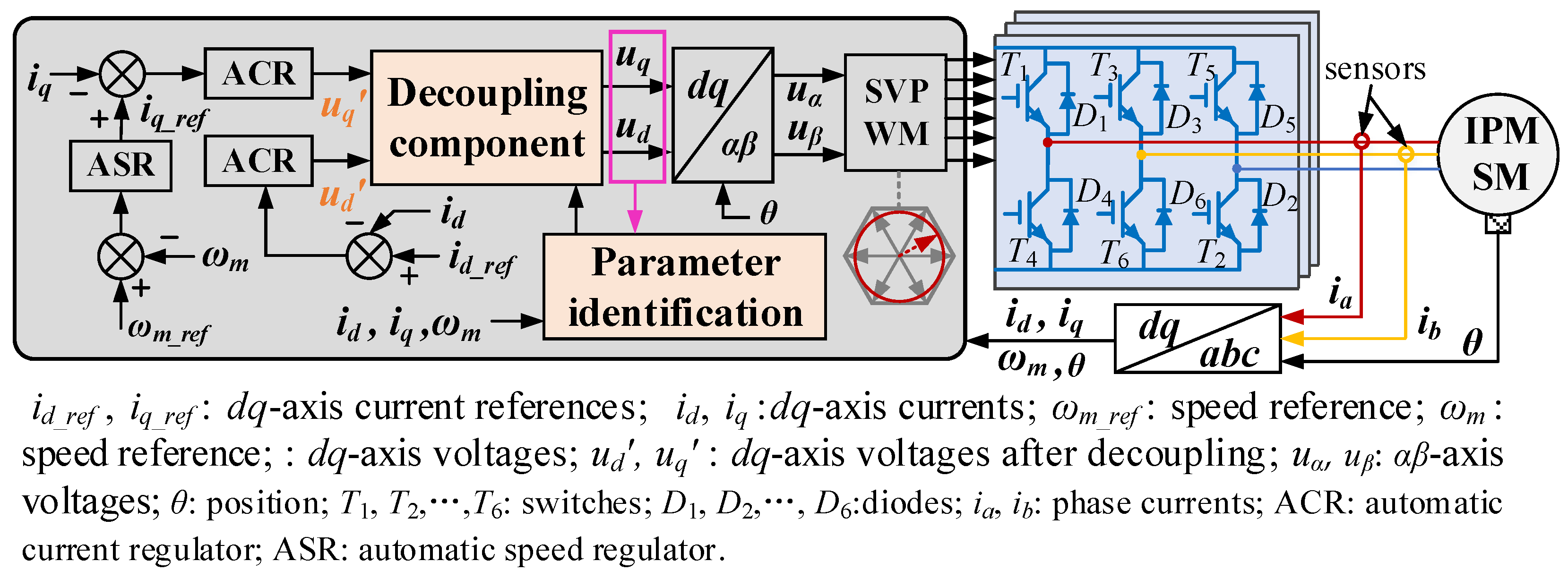
Figure 1. Structure of the deviation decoupling VC strategy.
Sustainability 14 11910 g001
Figure 2. Diagram of s-domain IPMSM model with current regulation process considered: (a) before decoupling; (b) after decoupling.
Sustainability 14 11910 g002
Figure 3. Relationship between the static current errors and the measured parameter values: (a) static errors versus Ld_m; (b) static errors versus Lq_m; (c) static errors versus ψf_m; (d) static errors versus Ld_m and Lq_m simultaneously.
Sustainability 14 11910 g003
Figure 4. Proposed Luenberger disturbance observer: (a) d-axis disturbance observer; (b) q-axis disturbance observer.
Sustainability 14 11910 g004
Figure 5. Simulation and experimental setups: (a) simulation system; (b) experimental test bench.
Sustainability 14 11910 g005
Figure 6. Comparative results before and after the proposed decoupling method is applied: (a) performance of VC without decoupling technique; (b) performance of the proposed decoupling VC.
Sustainability 14 11910 g006
Figure 7. System performance when inductance mismatch issue occurs without inductance identification: (a) Ld_m = 3Ld, Lq_m = 0.5Lq; (b) Ld_m = 0.5Ld, Lq_m = 3Lq.
Sustainability 14 11910 g007
Figure 8. System performance when inductance mismatch issue occurs with the proposed inductance identification method incorporated: (a) Ld_m = 3Ld, Lq_m = 0.5Lq; (b) Ld_m = 0.5Ld, Lq_m = 3Lq.
Sustainability 14 11910 g008
Figure 10. Steady-state performance: (a) without inductance mismatch; (b) with parameter mismatch (Ld_m = 3Ld, Lq_m = 0.5Lq), but no inductance identification; (c) with parameter mismatch (Ld_m = 3Ld, Lq_m = 0.5Lq) and inductance identification incorporated; (d) inductance identification results.
Sustainability 14 11910 g010
Table 1. Interior permanent magnet synchronous motor (IPMSM) parameters.
VariableDescriptionValueUnit
Udcbus voltage334V
Ldreal d-axis inductance1.2mH
Lqreal q-axis inductance2.4mH
Rsreal resistance0.18Ω
Pnumber of pole pairs3-
ψfPM flux0.078Wb
ωratedrated speed300rad/s
Iratedrated current10A
Publisher’s Note: MDPI stays neutral with regard to jurisdictional claims in published maps and institutional affiliations.