Abstract
When introducing new technologies, companies are repeatedly faced with choosing between solutions from different providers. Regardless of all the good technical characteristics of the technology, if it is chosen inappropriately, it can prove to be a cost driver instead of something that brings added value to the system. Aware of this, we considered selecting a real-time location system (RTLS) based on Ultra-wideband technology in the indoor work environment. In practice and theory, it has been proven that the introduction of the RTLS can have highly positive effects on performance and business sustainability indicators. When reviewing the literature, it was noticed that authors solely focus on the technical properties of the systems and prices when giving guidelines on selecting the optimal RTLS. This article aims to provide advanced guidelines for UWB RTLS selection, proposing a phased selection process which is the main novelty proposed and investigated in this research. The guidelines are based on fragmented recommendations in the scientific literature that have been identified, gathered, considered, and reasonably allocated to the advanced performance-oriented phased selection process. In practice, this approach enables decision-makers to choose the most efficient and most appropriate UWB RTLS for specific logistics systems.
1. Introduction
Nowadays, companies are optimizing their processes mainly by looking for methods to reduce manufacturing costs [1], increase sustainability performance, occupational health and safety [2] and digitalization. In doing so, they note that the great opportunity to save time and start business analytics depends on monitoring pieces of material, semi-finished products, products, and people in real time. Currently, location data in indoor work environments are mainly collected at the places of transactions, for example, at the start of work on the machine or when the goods are deposited on the shelf in the storage rack. Location data are based mainly on human work, namely scanning code marks, manual entry into the electronic information system, notes on paper, and the like. However, when the items travel between places of transactions, there are no records of their location, and their trace can be easily lost. Such semi-manual systems do not support real-time item routing, automatic transaction logging, dynamic production planning, reducing environmental impact, etc.
Systems that can provide real-time location data are so-called Real-time Location Systems (RTLS). The essence of RTLS is the locating or positioning of the items, to determine their location in a coordinate reference frame, concerning nodes concerning reference locations [3]. International standards organization (ISO) defines RTLSs as [4]: “wireless systems with the ability to locate the position of an item anywhere in a defined space (local, regional, global) at a point in time that is, or is close to, real-time”. The item can be an object or even a living being that has been assigned a unique code in the information system to which the master data relates and under which it or he/she is recognized.
Outdoor and indoor positioning are differentiated based on the environment where item monitoring is performed. Outdoor positioning is performed outside buildings, while indoor positioning is performed within buildings or enclosed structures [5,6]. Below we focus on indoor RTLS. Two types of indoor RTLS are in use: active and passive [7]. The main feature of the active systems is an electronic device attached to an item that transmits data to the information system in real time, thus enabling various data processing and decision-making activities. In the passive systems, the tracked item is not equipped with any device. The item’s location is estimated based on video analysis or the measured signal [8].
RTLS can be used in many different indoor work environments and is associated with many positive effects of technological upgrading of systems. According to Hammerin and Streitenberger [9], the main advantages of RTLS usage are control and reduction of stocks, increased cooperation within the supply chain, tracking of goods and components, potential to decrease environmental impact and external costs, support for decision-making systems, improved maintenance, and collision avoidance. Rácz-Szabó et al. [10] list some other advantages of using RTLS: cycle time optimization, improved warehousing and pallet management, weak-spot analysis, personnel monitoring, and improved production process performance. RTLS is also seen as a technology that can enhance the effects of introducing new logistics principles, such as Lean management, whose main features are eliminating all types of waste within production, shortening production time, and reducing inventories. With the help of the information obtained with RTLS, better organization and optimization of the production process can be achieved [11]. From a sustainability perspective, of which occupational health and safety is an important part, RTLS enables accident prevention approaches, productivity measurement and improvement, progress monitoring, and material management [2]. Furthermore, technologies that enable real-time data could reduce waste generation and increase resource efficiency [12]. The literature shows that RTLSs have immense potential for optimizing processes in different industries such as hospitals, livestock farming, care for the elderly, logistics, industry, and warehousing.
RTLSs differ in their use of different currently commercialized item locating technologies. A quick look at the scientific literature reveals that the Ultra-wideband (UWB) RTLS is the most generally applicable. It provides more accurate positioning than other available technologies since it works on larger bandwidths [13]. Despite this general advantage of UWB systems, the literature review reveals a few more that positively affect the work environment’s performance indicators [13,14,15,16]. One of the most important factors for decision-makers in selecting RTLS is the price of the needed equipment, installation, and startup investment. Franko et al. [17] pointed out that UWB technology is twice as expensive as Bluetooth, but other researchers confirmed the advantages of UWB over other technologies. Gharat et al. [18] compared RFID- and UWB-based RTLSs. Their conclusion based on the experiment is that UWB offers more accurate data but is more expensive and energy-consuming than RFID technology. In Section 3.1 on RTLS technologies, the article informatively presents technologies and justifies the reasons for favoring UWB technology.
As seen, decision-makers can expect to weigh functionality and price when choosing between different types of RTLSs. Impact on sustainability performance could also be an elective indicator; however, differences among technologies are not significant.
There is still no established standard for indoor localization, so selecting an RTLS must be done based on system requirements. Adler et al. [19] list the intervals of sending the location data for the tracked items and the required accuracy as important system requirements for selection. Besides system requirements, they also attach importance to the cost of the system and the type of environment in which the items will be tracked. If we follow the records in scientific journals, we find even more system requirements, but these are scattered across different articles:
- Type of technology used [1,8,20];
- Positioning algorithm [1,20,21];
- The ability to identify and differentiate identical objects [1];
- Precision and accuracy [1,5,7,8,10,20,21,22];
- Scalability [1,7,20,22];
- Space dimension [8,10,20];
- Number of possible tracked objects/max. number of devices allowing the system to still work properly [1,8];
- Complexity [1,20,21];
- Intended source of energy (batteries, recharging, etc.) [8];
- Cost [1,7,8,11,20,21,22];
- Availability [7];
- Robustness [22];
- Complexity [22];
- Environmental criteria [8];
- Battery properties [10];
- Latency in making locations updates/response time [5,8];
- Coverage and its resolution [5,7,8,21,22];
- Privacy/control how information is collected and used [7];
- Buildings’ infrastructure impact [5] and
- Effect of random errors caused by signal interference and reflection [5].
Many authors proved that several selection criteria need to be considered in the selection process or that it is necessary to check whether the technology enables the fulfilment of several system requirements. Higher demands, however, are very likely to be associated with a higher price. The selection process is, therefore, at least a two-phase process. Jachimczyk [8] emphasizes that decision-makers need to consider several aspects such as software, installation, licenses, employee training, maintenance, potential benefits and traps and customer support when thinking about the price of the selected RTLS system.
Gladysz and Santarek [23] proposed how to choose the best RTLS system for a specific case, focused on the industrial environment (warehouse, manufacturing). The methodology of RTLS assessment and selection is structured and leads the decision-makers through six (6) steps:
- Definition of needs for RTLS (What RTLS will be used for?);
- Analysis of RTLS market (check if existing systems satisfy needs);
- Synthesis of previous steps (necessary for the definition of alternatives);
- Determination of weights for criteria (the list of criteria is divided into three groups: financial criteria, implementation criteria, technical criteria, based on Budak and Ustundag [24] and Asosheh and Khanifar [25]),
- Weighting criteria (group and fuzzy Analytic Hierarchy Process proposed by Budak and Ustundag [24]),
- Ranking of alternatives (TOPSIS method).
The criteria used by Gladysz and Santarek are [23]: cost, return on investment (ROI), implementation time, organizational learning, experience, process re-engineering, usability, accuracy, response time, upgradability, maintainability, compatibility, security, and reliability. The authors themselves noted that the above list of criteria is not optimal and is too extensive. It is unclear why criteria are put on the list and how they can help choose an optimal system. The developed procedure serves to select between different RTLS technologies and is not intended for selecting only among the available UWB RTLSs.
Cwikla et al. [1] proposed a list of requirements for RTLS to be in optimal support to management and production engineering, which includes: the type of objects for localization, required positioning accuracy, the ability to identify and differentiate identical objects, frequency of refreshing location information, need for continuity of location determination, need to provide a line of sight, immunity to interferences and cost. All proposed features are explained understandably. The study focuses on the production environment, and the selection process supports the choice between different technologies.
Researchers have already been involved in making recommendations for selecting RTLS; however, these are not yet optimal and enable significant improvements. With respect to the reviewed literature, we believe that the proposed criteria are not well explained. None of the studies has focused specifically on choosing between UBW RTLSs. The studies also differ according to the selection criteria, and all treat the selection process as a single-phase decision process, where the criteria are only differently weighted. This is, however, not how real logistics operations function, and therefore further consideration should be given to the use of phased process.
The novelty of this paper is a performance-oriented selection model for the UWB RLTS as a multi-phase process enabling better selection of technology. Moreover, this article presents an advanced abbreviated list of UWB RTLS selection criteria with an explanation of the criteria and organization of the decision-making process in multiple phases. The results of this paper could be used by decision-makers who have already decided to use UWB RTLS and have to decide between several different offers on the market which are of different efficiencies and appropriateness for specific logistics systems. The article will help them understand why each criterion is important and how it can influence the process.
The remainder of the paper is structured as follows. The second chapter explains a method for the literature review with an explanation of the criteria on which articles were selected for further analysis. The focus of the literature review is to analyze important criteria for phased UWB RTLS selection. The third chapter explains RTLS systems and their basic properties as well as different positioning methods. It lists and examines different RTLS technologies to support the decision for a selection process between UWB technology and the claim that this technology is the most accurate among available technologies for RTLSs. The fourth chapter summarizes findings of analysis on performed experimental work with UWB RTLSs. It explains in detail the new proposed performance-oriented decision-making approach and is concluded with a list of system requirements that needs to be defined before starting the RTLS performance evaluation process and their importance for the optimal UWB RTLS selection. The fifth chapter discusses our findings. Validation of the proposed UWB RTLS selection methodology with the proposed form for decision-makers is presented in chapter six. The article concludes with a description of the paper’s originality and guidelines for further research work.
2. Materials and Methods
As seen in Figure 1, the scientific literature was searched through online databases ScienceDirect, MDPI Open Access Journals, IEEE Xplore, SpringerLink and ResearchGate with following key words and their combinations: RTLS, UWB, RTLS Comparison, RTLS Overview and RTLS measurement. Sixty-five (65) articles were found for review. Out of them, nineteen (19) articles were relevant to the research and selected for analyses based on the following criteria:
- Describes the topic (e.g., explanation of concepts and contains definitions);
- The experiment was performed by using UWB RTLS technology and discussing the accuracy of the results;
- The article contains novel information or was published in 2011 or later.
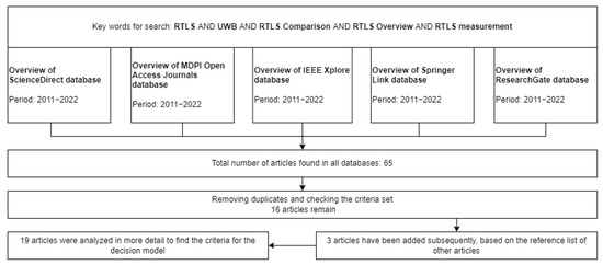
Figure 1.
Paper identification and selection process within the research process.
After the literature review, the new UWB RTLS selection methodology was developed, based on a form for collecting data on the production environment in which the technology will be introduced. The selection method is proposed in multiple phases. The selection methodology was used in a real-life procedure on the example of a tool company in the first quarter of 2022. Thanks to the responsible persons in the Slovenian tool company and providers of RTLS UWB systems, we have supplemented the methodology.
3. Real-Time Location Systems and Their Basic Properties
Most wireless networking concepts were designed primarily for data and audio transmission. In the desire to realize the concept of Industry 4.0 in practice, researchers began to consider the requirements and possible approaches to automating the tracking and localization of items. Dardari et al. [3] emphasize that no technology could ensure satisfactory operation in all conditions and environments, meeting space coverage and localization accuracy criteria, but all have some advantages and disadvantages. Five technologies that can be used to operate RTLS have been analyzed and cross-compared. All of them are offered on the market. The diversity and differentiation of technologies make it difficult to decide on the choice of the optimal RTLS configuration. Short descriptions of the individual technologies are given below, while the specific advantages, disadvantages, accuracy and read range are listed in Table 1.

Table 1.
Features of individual technologies.
Wi-Fi technology is one of the most widely used localization technologies because (1) Wi-Fi is designed for many different devices, and (2) Wi-Fi can receive a signal at different access points. Wi-Fi technology has also been developed and optimized for the needs of Internet of Things (IoT) services [26,27].
Bluetooth is considered to be a technology for exchanging data over short distances. This technology is recognized as suitable for proximity detection, not as a solution for item localization. One version of this technology is Bluetooth Low Energy (BLE), also known as Bluetooth 4.0 or Bluetooth Smart. BLE was developed for situations where the flow of information is lower [26,27].
ZigBee is the technology based on the Institute of Electrical and Electronics Engineers (IEEE) Standards Association’s 802.15 specifications and is known for low power consumption and secure networking because the information travelling through the system is secured with encryption. It was designed to remedy the shortcomings of Bluetooth and Wi-Fi [27,28,29].
Radio Frequency Identification (RFID) is a technology used for data transmission and storage. Two types of RFID are known: active and passive RFID. They differ in the design of the RFID tag through which the item is marked [8,26].
UWB is a technology that has been used for many years for military purposes to detect and acquire high-resolution images [13]. Recently, interest in this topic and technology has grown because of its introduction into localization services. An important area within these services is IoT, and within it, this technology is seen as very useful in autonomous industrial systems. The technology is highly resistant to interference and various obstacles in space (liquids and metals are an exception) while allowing fast data flow. It is highly praised for its accuracy. Localization error is up to 10 cm [8,13,26]. UWB technology has been used for many years to set up RTLS systems. UWB can broadcast on a wide range of frequencies, offering a wide range of applications in RTLS [30]. The advantages of UWB RTLS are [30,31]:
- Accuracy of less than 10 cm;
- Identification—in the case of several tags (transmitters) in the locating network, each tag has a known identity to have an informative overview when tracking locations in the application;
- Low energy consumption—operation of the system requires a small amount of energy;
- The uninterrupted connection between devices—when many devices in the room emit a signal, signal interference occurs. This disrupts communication, which can lead to distorted measurements. Among comparable technologies, UWB RTLSs prove to be the most reliable;
- Security—the system offers strong security against intrusions into the system;
- Low latency—fast data processing allows a short time between the movement of the transmitter in real space and the displayed movement in the application).
The listed advantages mostly exceed the advantages of Wi-Fi, Bluetooth, Zigbee and RFID. However, we cannot claim that the number of UWB RTLS implementations is ahead of other technologies in practice.
3.1. UWB RTLS Components and Operation
Core components of RTLS based on UWB technology are the tracking device (tag), location sensors, and the location engine software. For the functioning of the RTLS, some additional parts are also needed, including middleware for recording and transmission of data and the user software that allows system management. The software could run on one or more different machines (computers). Tags are devices that are built into or attached to the tracked items. Tags can also be equipped with push buttons (or call buttons). These can be used as panic buttons for summoning emergency responses in the medical environment [6].
Anchors are static electronic devices that receive a signal from the tags. There must be a minimum of four anchors per layout. They must be placed in such a way as to establish a homogeneous network between them over the entire area within which the monitoring should be enabled [32]. The main anchor is a stationary device and is a collection center of information obtained through other receivers. The task of the main anchor is to obtain information obtained by other receivers from the tags. It transmits this information to the application via a wireless or Ethernet network. The main anchor communicates with all other anchors at regular intervals to control them and to ensure that there are no changes in the established network [31].
The received signals are forwarded to the server, which processes this data and thus determines or assesses the object’s current location. The operation of the software depends on the system manufacturer, as each company has its own approach. The software uses various algorithms to perform calculations and determine the location of the tags. The software must have information on the exact location of the anchors in the room to perform accurate calculations. Therefore, the master anchor also communicates with other receivers to ensure quality location data [31].
3.2. Positioning Methods
Determining the position of the tag takes place in two phases. First, the distance of the tag from the receiver is determined. This information is obtained using AOA (Angle of arrival), TOA (Time of arrival), RSSI (Received Signal Strength Indicator) and TDOA (Time Difference of Arrival) techniques. In the second phase, the tag’s position in space is determined by using the method for determining the location. The location method uses the data obtained in the first phase and determines the tag’s location in a coordinate reference frame [8]. In general, the location can be described in three ways: (1) symbolically (e.g., the predefined zone in which the item is located), (2) as absolute (exact) location and relative location and (3) determination of the location based on a nearby known object [3,26].
The main goal of using location methods is to minimize errors because of disruptors of results in the environment to achieve the most accurate results [3,26]. The most known and widespread location methods are fingerprinting, proximity detection and lateration.
Fingerprinting is a two-phase location method divided into offline and online phases, also known as the localization phase. The first phase records the signal strength at a known location (i.e., the coordinates are known) from several anchors/access points, sometimes at different angles. Collected data are stored in a database. In the localization phase, the received signal strength is compared with those stored in the database. The advantage of using this method is that it does not require any assumptions about the environment. The created model is based on the measured data. However, any change in the environment, e.g., adding/removing access points or furniture, results in a required update of the reference data stored in a database [8,26,27,33].
Proximity detection is one of the simplest location methods. Its operation is based on detecting a tracked object near predefined points. Each of these points has a specific radius within which it transmits the signal. If the tracked object receives a signal, it is in a particular neighborhood of one of these points. Here, it should be emphasized that the given result is the approximate space where the object is located rather than the exact location. This space is determined based on the intersection of the various circuits formed by the transmitted signals. This method is suitable for more affordable devices, especially if many tracking badges are needed [3,8,27].
The third location method is lateration. It determines a location in terms of measured lengths from a tracked object to points in space whose location is known. It is also known as the range measurement technique. The method uses at least three receivers to determine the location or triangulation. Multiple receivers can also be used for detection and increasing accuracy. The approach is known as multilateration. It can determine the location of an object in both two-dimensional (2D) and three-dimensional (3D) spaces. The distance from the sensors to the tracked object is required, and with this data being used in algorithms, it is possible to find the intersection of geometric shapes (circles, parabola), which represents the location of the object [3,8,27].
4. Results
4.1. Real-Time Location Systems Overview
Table 2 presents relevant data from 19 research articles on UWB RTLS that deal with the system’s accuracy in different environments. Articles were published between 2011 and 2022. Most of the research was conducted in 2018 in laboratories or real authentic environments. We were interested in answering the research question “How do the work system’s properties affect the performance or accuracy of UWB RTLS?” We did not limit ourselves to a specific type of work environment.
Table 2.
Review of relevant data and results from UWB RTLS experiments.
UWB RTLSs have been tested in different environments. In all environments, they turned out to be reliable and accurate. The experimental real work environments during processes were medical [34], sports [35,44], dairy house [36] and industry [13]. Some RTLSs have been tested in work environments, but with no processes. Those environments were barn [43], space simulating construction conditions [37], office [38], industrial warehouse [39] and garage [22]. Most of the analyzed tests were done in different types of empty rooms [8,32,40,41,42]. One test was carried out outside—on the roof of the institute, although RTLSs are primarily designed for indoor use [45] and one was done only with the computer simulation of the system [46].
Besides the usage in different environments and conditions, UWB RTLSs have been tested with a different number of tags and anchors. Some studies used only one tag for location [16,22,32,37,38,39,40,41,42,45], some tested more than tag one simultaneously [1,8,34,35,36,37,43]. In an experiment by Barbieri et al. [43], different RTLSs systems were used simultaneously to test if they interference with each other. Given the basic requirements and performance of the systems, more than three anchors were used in almost all studies. A study by Pudlovskiy et al. [42] investigated the effect of the number of anchors used on the localization results, using between one and seven anchors. The highest number of anchors used in the analyzed literature was eight by Maalek and Sedeghpour [37].
The number of tags needed depends on the purpose of the survey, as well as the objects being tracked. This is especially important in the case of locating people and animals. Most of the research we analyzed followed people in different settings and situations. The positions of tags tested were different. When tracking the elderly [34], the tags were hung around their neck and stuck under a shirt. In a sports game [35], tags on the head were tested as this position did not bother the sportsman. In a study by Maalek and Sadeghpour [37], tags were placed on the head and shoulders to determine the direction of a person’s movement. In an experiment in a garage [22], people carried the tag in their hands. In the study by Otim et al. [16], the positions of tags on different parts of the body were tested (chest, arm, ankle, wrist, thigh, forehead, hand). Four experiments were carried out based on predetermined points on the floor, on which the tags were fixed [8,32,38,41]. Some tests were done by tracking automatic mock trains [37,45] and wheeled robots [42]. One study was carried out by tracking animals, with tags installed into animals’ ears [36].
The results on the accuracy of the systems vary between the studies analyzed, depending on the study purpose and specific data the authors needed. The results gathered were validated in different ways. The test usage of RTLS to track the elderly only required information on which predefined area the elderly person was in, for how long, and whether they had socialized with anyone during that time and for how long. To confirm the accuracy of the data, the researcher spent 43.8 h observing the elderly involved in the experiment and taking notes on what they were doing [34]. During tests in sports disciplines, authors monitored whether there was a difference in the accuracy of the system at the edges and inside the court [35] and tracked the distance a sportsman walked or ran [35,44]. In both cases, the trundle wheel was used to track the distance traveled by the sportsman. In some studies, the authors were interested in whether there was any deviation from the predefined route taken by the person in the data obtained by the system. The validation was carried out using a pre-plotted route on the ground and in RTLS software [22,45]. Two studies investigated whether speed affects tracking accuracy [37,44] and whether RTLS can be used to determine the direction of an object [37]. However, most of the research has focused on the accuracy of localization in terms of the exact coordinates of the points [1,8,11,32,36,38,39,40,41,42,43,46]. All mentioned that research which focuses on coordinates validate their results with predefined points in the space. Only in a study in a dairy house [36], cameras were placed around the room to track and determine the exact locations of the cows.
The accuracy achieved by the RTLSs in the experiments was observed and investigated. We noted that the results on accuracy are presented in diverse ways. Some report average measurement errors, while others average accuracy. Two of the analyzed experiments [32,34] researched only if a specific item is in a certain area or not. For the observation of the elderly, it was revealed that during the 14-day observed period, 92.6% of the rooms in which the elderly was found during the day were successfully identified. In the case of a laboratory experiment [32], an average of 72.93% of successful job detections were confirmed. However, RTLS’s performance varies according on the workplace’s distance from the anchor. The average measurement error was higher around the master anchor. Other studies show that UWB-based RTLSs are accurate in a variety of environments.
The main finding is that when choosing a UWB RTLS version/provider, the same data need to be collected regardless of the work environment type in which the system will be used. Furthermore, the use of RTLS UWB is reliable even in environments where other positioning systems do not provide reliable results. The measurement error is less than 40 cm, which meets most production requirements.
4.2. Proposed UWB RTLS Selection Methodology
The selection of the UWB RTLS should be made in two phases (Figure 2). In the first phase, all required properties must be listed to determine the necessary functionalities of the system. At the same time, additional economic constraints need to be defined. The goal of data collection must be defined, and the programs that will use and perhaps even analyze the data obtained through the measurements must be listed. Providers of UWB RTLS solutions are then sought on the market, and together with them, the feasibility of realizing the requirements with the offered solutions is checked. Pilot applications are also carried out if this proves helpful and possible.
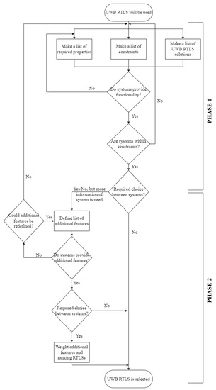
Figure 2.
Phased organized UWB RTLS selection process.
The output of the first step is zero to several UWB RTLSs that correspond to the set functionalities. If the output is zero, then the determined functionalities must be redefined, and the first step is repeated. In the second step, it is checked whether the individual bid of the supplier, which has met the requirements of the first phase of selection, does not exceed the defined constraints. The output of this last step is also zero to several UWB RTLSs. If the result is zero RTLS, the process must be returned at the beginning. If several offers meet both requirements of the first phase, the selection process continues with the second phase. In this phase, additional features are defined that may affect the user experience. Even if the output of the last step in the first phase is only one relevant bid, it is still possible to verify compliance with the additional requirements that emerged during the selection process, most often due to improved knowledge of the capabilities of UWB RTLS.
If available systems do not meet the set of additional features, the decision about the importance of additional features must be made. If the defined list is not of essential importance for the implementation and usage of the selected RTLS and could be redefined, the process of selection is returned to the step of defining additional features to redefine them. If the decisionmaker judges that the defined additional features are very important and that some of the basic requirements could be redefined, the process returns to the beginning of the first phase to reconsider the initial selection data. If the result of this step is more suitable RTLSs, the additional features are weighted based on the decision-maker decision and the ranking of alternatives is made. The best RTLS that meets all the required properties, constraints and additional features is selected.
Table 3 states:
- the list of required properties that must be defined before the selection of UWB RTLS to determine its functionality;
- the list of constraints that have a decisive influence on the selection of the system even if it meets all system requirements;
- some additional features that may affect the user experience and assist in deciding when more than one system has met both requirements and constraints.
Table 3.
Selection settings in the process of UWB RTLS selection.
Table 3.
Selection settings in the process of UWB RTLS selection.
| Selection Settings | Description | |
|---|---|---|
| Determining Required Properties | ||
| (1) | The environment in which the system will be set up |
|
| (2) | Properties of tracked items |
|
| (3) | Type of data required/accuracy |
|
| (4) | Software that will use the data captured |
|
| Determining constraints | ||
| (1) | Cost |
|
| (2) | Compatibility |
|
| Additional features | ||
| (1) | Implementation time |
|
| (2) | User experience |
|
Below selection settings are described in more detail. Reasons for listing are given.
4.3. Explanation of Selection Required Properties That Define the System’s Functionality (Phase 1)
4.3.1. The Environment in Which the System Will Be Set Up
Data about the work environment in which the UWB RTLS equipment will be installed are needed to check the physical feasibility of the technological upgrade. The possibility of installing receivers must be considered with the awareness that RTLS components should not interfere with the work processes. The type of installation affects the price and can significantly increase the investment. Anchors’ installation height affects the accuracy of locating.
The second important feature of the work environment is climatic conditions since the components of the UWB RTLS can be damaged at extremely high or low temperatures, in very humid conditions, or due to the presence of chemically aggressive substances. Data on operating temperature range, humidity, airborne reactants, and dust must be collected. Changing climatic conditions could also contribute to the sustainability performance of the system (decreasing or increasing it) and might not be favorable.
The dimensions and layout of the work environment must be described. The required number of anchors depends on the floor plan dimensions. The layout configuration affects the anchor mounting height. However, the number and height of anchor attachments are strongly associated with costs and related material use as well as embodied energy.
UWB RTLSs also work reliably in a metallic environment if adequately designed. For this purpose, data on the zones in the layout in which the items will move are required. There must be no wall, workstation, or other objects between the anchors and transmitters. This information determines the number of anchors and the feasibility of planned technological upgrades.
4.3.2. Properties of Tracked Items
Information on the speed and frequency of movement of tracked items is required. Higher speeds require more frequent signal transmission and higher power consumption to power the tags. Moving tags faster also requires more advanced software support to achieve the required location accuracy. The type of selected tags, the way the tags are powered and from which source, and their settings depend on the data. Listed data affect the size of the investment and the size of the variable maintenance costs of the system after installation.
It is important to define and describe the concept of item tracking. Tags can be used to equip each item or to attach them to item holders in the form of boxes, pallets, or the like. The concept significantly impacts on size and mass that tags can have. Each provider has different tag designs. Tags can have additional built-in sensors to detect rotation, height, acceleration, etc. Greater tag functionality is associated with a higher price.
Differentiation between individual items can be necessary in some business cases. The price for RTLS implementation increases with the number of tags used. Data on the number of items to be tracked simultaneously is needed. RTLS can be limited by the number of tags that can be monitored simultaneously.
4.3.3. Type of Data Required/Accuracy
The primary added value of using RTLS is real-time data on the item’s location, which frees the user from capturing location data at fixed and rare layout locations. The current location data alone is of little value. Data value increases when it is used for a higher purpose. For example, to automatically record material transactions in material flow from receipt to shipment from the company, the known route of the item can raise the level of safety in terms of reducing forklift collisions, etc. A faster ROI can be expected if the location data is used for multiple purposes. The user considers and describes the objectives of the use of RTLS and determines the necessary data accordingly.
If only information about the pre-defined zone in which the tracked item is located is needed, a very precise system is not necessary. On the other hand, if exact location coordinates are needed, a more accurate system will be required. The accuracy of the system affects the price, and it makes no sense to choose a very accurate system if such accuracy is not necessary.
At the same time, it is important to answer whether it is needed to locate objects only in 2D space (x and y-coordinates) or in 3D. For 3D tracking, an additional sensor needs to be installed in a tag.
4.3.4. Software That Will Use the Data Captured
After the purpose of capturing data is set and it is clear what type of data will be needed for some additional analyses, the list of software that will be used and analyzed needs to be set. Additional software for data is needed since the RTLSs only generate location data that other software import as input data to perform their functions. It is also important to define the data type, which is needed to prepare the set list of software. In order to be effective, there is a tendency to automate the data analysis process.
4.4. Explanation of Selection Settings That Define Constraints (Phase 1)
Defined selection settings that describe the system’s functionality allow listing the constraints. Companies have different amounts of financial resources to invest in technological upgrades. Occasionally, national, or European sources of funding appear. In addition, it is possible to intervene in production only during specific time-limited periods of the year, for example, during collective annual leave. Companies are further constrained in their choice due to existing information solutions and the availability of their upgrade providers. All this needs to be reconsidered and clear boundaries set within which the offer should be placed.
4.4.1. Cost
Cost is a frequently mentioned decision criterion in the scientific literature, and is especially important for the managers in the concerned organizations. It is important to set a cost cap as this saves valuable time for the company and providers. Often, bidders are unwilling to prepare bids if they find that the company is not sufficiently prepared for the coordination process. The purchase of an RTLS system is not just a purchase of a product but an individual development of a customized product. Management has to define maximum acceptable investment, including the cost of adapting in-house software solutions. It must have a clear view of the upper limit for ROI. In addition to the fixed cost limit, it is important to consider the variable cost limit due to the use of the new system. The system’s equipment will need maintenance, the batteries will need to be replaced, obsolete batteries end-of-life disposal or recycling will need to be considered, license rental costs will be incurred, etc.
4.4.2. Compatibility
Three compatibility tests must be performed: (1) hardware (is RTLS compatible with different hardware configurations?); (2) operating systems (is RTLS compatible with different operating systems like Windows, Unix, Mas OS, etc.); and (3) software (is RTLS compatible with other software used)? If compatibility is not possible, which is unlikely but still possible, the initial investment will increase.
4.5. Explanation of Selection Settings That Define the Additional Features (Phase 2)
Suppose several RTLSs meet functionality requirements and constraints in the decision-making process. In that case, the company can define additional features to complete the selection. Additional features can be: required time from project kick-off to independent use of the system, payment terms, availability of a call center for users, spare parts delivery time and prices, etc. It is up to the decision-maker to set additional restrictions in such a way that they are suitable according to the needs of the environment in which the system is to be implemented.
5. Discussion
The developed performance-oriented UWB RTLS decision-making approach is based on a scientific literature review and the authors’ experience. The article compiles lessons learned from experimental technology tests in different work environments. Overlapping findings in the results and breakthrough ideas were identified. The shortcoming of most of the considered articles is in the mere listing of properties, criteria, and limitations without added descriptions and explanations. This article bridges this gap and offers a phased organization of the decision-making process due to the dependence of the price of the technological upgrade on the required functionality in the existing work environment. In the first decision-making phase, the system is configured, and its price is consequently determined. Only the fulfilment of the required functionality allows the decision-maker to move to the second phase of the decision-making process, where it is determined whether the offer is within the available funds and if user’s requirements (e.g., learning difficulty, user experience, implementation time) are met. In the following, we discuss the selection settings from the decision-maker’s point of view.
5.1. The Work Environment in Which the System Will Be Set Up
Places of installation of anchors are influenced by the physical infrastructure and work processes, and in some cases, by tracked items. The existing infrastructure, in terms of building, wall layout, height and span of production halls, and materials used can pose a serious challenge for installing an RTLS system and can significantly contribute to cost. From a literature review, measurements in a barn [36] stand out, where the authors pointed out that anchors need to be placed high enough so that animals cannot reach them. The same research pointed out that tags used in their experiment had to be protected with insulating plastic tape and water-resistant bags due to water, mud, and high relative humidity presence. This additional protection certainly does not create comfort for the user. In addition to the system, it is also necessary to take care of protection during the operation phase. Water-resistant bags are not a professional solution but are cheap and easily accessible. In any case, RTLS systems are still being developed and will get their final shape in the coming years.
Anchor placement options are also critical in location accuracy, as in the example by Gajšek and Šinko [32], where tested RTLS was not accurate enough even for recognizing that the tag was inside determined zones. The read location may be less accurate in certain zones inside an RTLS-covered layout. This is not an unsolvable problem but requires more effort in the installation phase. It can be bridged by rearranging anchors or adding algorithms to the RTLS software part. In any case, this is reflected in the time and cost of implementation.
If the work environment contains many metallic surfaces, it is possible to interface with anchors [37]. Measurement error could be caused by straight propagation throughout a blocking material, such as walls and other indoor obstacles [39]. The work environment’s layout and topology impact the number of anchors needed to cover all areas—the more reinforced walls the environment has, the more anchors will be needed [34]. Directly related to the costs also is the floor area size. A bigger floor area requires more anchors [8,34,43] as well as contributing to higher use of land as one of the potential environmental indicators.
5.2. Properties of Tracked Objects
The decision-maker has little influence over whether the tracked items will be classified as static or dynamic. The frequency of movement of items largely depends on the type of production, the location of machines, and the sequence of technological operations. Research by Maalek and Sadeghpour [37] shows that tracking static items is more accurate than tracking dynamic items. When selecting tags and setting their settings, it is important to consider the item’s speed, as the accuracy of locating decreases with the increasing item’s speed [37,44]. The accuracy in the 2D environment is more affected by the speed change than accuracy in the 3D [37]. As proposed by Cwikla et al. [1], if the RTLS is used for supporting production, the accuracy of 0.1–1 m is accurate enough, but this accuracy is not good enough if autonomous robots or vehicles are tracked.
In tracking people, it is important that wearing tags does not interfere with their daily work and tasks. In the nursing home [34], they placed tags loosely around the necks of the elderly. Tags were discreetly stuck under a pullover or shirt. Tag attachment on the wrist and arm was assessed as too obtrusive. Likewise, in sports, the place of tag attachment proved to be very important since players must move their legs, arms, and heads freely [35]. The range of error depends on where the wearable sensor is placed on the body. If the human body blocks the path of the signal, this is reflected in errors from a few decimeters to several meters [16]. The link between attaching a tag to the body and the weight and size of the tag in livestock farming is particularly emphasized by Porto et al. [36]. In the case of animals, it is possible to attach the tag only to the ear of the animal, as otherwise, it could be damaged or lost by the animal. A change in animal behavior because of the weight in the ear was also observed.
Franko et al. [17] experimented in a warehouse environment. UWB tags were attached to forklifts. The most important finding is the importance of the thoughtful placement of the tags in the appropriate places. It is inappropriate to put a tag under any cover or other metal objects due to the immediately reduced accuracy of localization.
When tracking items, it is important to distinguish between specific, identical, and similar objects [21]. For example, Hulka et al. [44] emphasized the importance of knowing which cow is in which zone. Differentiation between tracked persons was also important in the case of a nursing home [34], where the RTLS was used as a support system to track the habits of the people. They needed to know each person’s pattern of movements between rooms. An important piece of information is the number of traced tags per unit area. Jachimczyk [8] proved that the accuracy of the measured distances is affected by a number of tags and the complexity of their paths. Another issue is that tagging might also be socially unacceptable for some cultures and employees. Staff might oppose integrating RTLS into their working processes due to negative perspectives on personal data gathering and misunderstanding it as over-controlling. This might also impact the social responsibility performance of specific companies.
5.3. Type of Data Required/Accuracy
One of the highlighted features of the UWB RTLS is the accuracy of locating items. However, accuracy of the measured values should not be required in a narrow tolerance field when this is not necessary to achieve the set business goal. If the automatic recording of stocks in the warehouse is required, the information on the item’s departure from the previously defined zone is sufficient to change the stock. It is worth remembering that higher accuracy is associated with a higher cost. If data on precise item location is not needed, it is pointless to invest in a highly accurate system [28]. However, in some industries and processes, it is vital to know as accurately as possible the coordinates of the location of the tracked item [17,32].
RTLS can also be used in cases where it is enough to track only whether the tracked item is in the predefined zone or not. Another example is described in a nursing home [34], where observers needed data about rooms visited by the elderly and the time of their stay in them. Porto et al. [36] described a case including dairy cows, where the farmer needs to locate cows inside predefined zones. In the case of basketball, analytics perform time-motion analysis to be aware of the distance run by players [35].
5.4. Software That Will Use the Data Captured
The automatic data processing is the gap in the scientific literature. As seen from the literature review, the data captured with the RTLSs are analyzed after completing experiments. However, in real work environments the necessary data must be available in real time and not only after additional analyses. There is usually no time for additional manual analyses, since analyses are done in some other software. No article was found that discussed the automation of data analysis.
5.5. Cost
Cwikla et al. [1] and Gladysz and Santarek [23] addressed price as an equivalent decision variable to other selection settings that define the system’s functionality. We argue that the price should not be the equivalent criterion to the functional requirements. We advocate a two-phase organization of the RTLS selection process. The selection process can be started by defining the full desired functionality, which is reduced in case of exceeding the maximum investment limit. In case of the need to lower the price, it makes sense to think about establishing connections with fewer in-house software solutions. It is necessary to start with at least one. In this way, we do not impair the functionality of UWB RTLS. We only exceptionally intervene in the list of its initially defined UWB RTLS system requirements.
5.6. Compatibility
Compatibility of the data, gathered with the RTLS systems with other software solutions is another gap in the scientific literature. As seen from the literature review, researchers are primarily focused on the accuracy of the localization. No article was found to discuss the use of location data in work environments systematically. Examples and areas of use of location data can be deduced from the articles indirectly, as the articles are aimed at researching accuracy.
6. Validation of Selection Methodology for RTLS UWB Variant/Provider Selection
The study concluded that all RTLS UWB configurations are based on the same work environment and work process data. Based on this finding, we started to develop a data entry form that the manufacturing company would fill out and forward to various RTLS providers during the RTLS UWB selection phase on the market. The data entry form is not only intended for the preparation of data, but also gives the manufacturing company an insight into the topics they must pay attention to, so that the technological acquisition will really serve its purpose the best.
The developed data entry form is presented as a table (Table 4 and Table 5), followed by the result of the validation with a tool company. The form was developed to cover all the steps of the selection methodology, and then tested. After the first collection of data from the production company, the providers several times requested additional data, which led to the completion of the data entry form. The last version was confirmed after the selection of the RTLS provider, i.e., when the selection process ended. The data entry form in Table 3 and Table 4 guides the manufacturing company through the cognitive process of system configuration and data collecting. It refers the responsible person to collect all needed information for RTLS service providers to make offers.
Table 4.
Data entry form to collect data for system provider.
Table 5.
Financial framework definition.
6.1. Data Entry Form
The data entry form is divided into two parts, each in own table. The first part (Table 4) contains information for the RTLS provider. It starts with the definition of the general purpose for implementing RTLS and purposes of tracking items. The author of the request must describe anchor placement options, climatic conditions, and production hall geometry. Changing climatic factors can also significantly contribute to system sustainability. The precise layout of the production hall must be attached. It must contain data on the height of partitions and working centers because they can be an obstacle to data exchange. Further, tracked items must be described in detail; photos can be attached. Since UWB RTLS is suitable for locating objects and people, the section for defining the tracked items is divided into two parts. The person filling out the form fills out the one that corresponds to the specific situation. The form requires the list of connected software, hardware properties and operation system type. The last part of the form provides information on expected timelines for technology implementation and training, and the importance of user-friendly interfaces.
By completing Table 4, all data for RTLS providers are collected. Manufacturing companies are also invited to attach photos of work centers, partition walls, ceilings, production halls from different angles and items to be tracked. The definition of the financial framework follows (Table 5), which is also a part of data entry form but is not sent to the RTLS provider.
The RTLS provider can prepare an offer based on data from Table 3 and attached photos and layout. This also happened in the validation process. We found that it is necessary to attach to the completed Table 4 also the layout of the production hall, adding the heights of walls and work centers to the floor plan. It is also necessary to add as many photos as possible in case an on-site visit is not possible.
6.2. Validation
The RTLS selection methodology was described to the responsible persons in the tool company which was just before the selection of the RTLS provider. The company agreed to select the provider according to the proposed methodology and use the developed data entry form presented in Table 4 and Table 5. The company completed Table 4 and Table 5. Draft Table 4 was sent to four RTLS providers. The tool company attached the layout. RTLS providers requested additional data in three iteration steps. During this time, the Table 4 was finalized. When there were no more requests for additional data, we considered the data entry form as validated. In addition to the completed Table 4, the company sent to the RTLS providers various photos of tracked items, views of the production hall from different standing points, pictures of partition walls and production centers. We can conclude that most of the data RTLS providers need will be received with a completed Table 4, while a smaller part of the data will always be obtained through additional communication.
In anticipation of offers from RTLS providers, the company also completed Table 4. In our case, one of the four RTLS providers requested an on-site visit before offering the solution.
The tool company received four bids. They differed in the financial part, the design and dimensions of the tags, and the time frames. All offers were within the financial framework. It was necessary to define an additional selection criterion. The tool company checked the feasibility of pilot demonstrations of operation in its premises. The final decision was made based on the results of the pilot operation demonstration, as one provider failed to establish a working environment, two of the demonstrations raised slight doubts about the bidder’s expertise, and the fourth was the fastest to establish a functioning system that continuously sent location data during tags movement through the production hall. RTLS’s accuracy was not checked.
7. Conclusions
The fact that RTLS can be used for solving different challenges of automated data processing in work environments and implemented for different purposes is especially beneficial for users. In all practical applications, UWB RTLS is used as a resource for real-time location data about objects or living beings. For what purpose location data is used, is in the domain of the individual organization. Although the use of UWB RTLS offers many advantages (e.g., increased efficiency of the processes, reduced quantity of raw materials used and production waste, enabling accident prevention approaches) and affects the company’s sustainability, careful consideration is needed before its implementation. A prerequisite is a clear vision of the business goal. Usually, it is set as data flow automation, transparency of activities, event forecasting, and advanced business analytics.
This article proposes a new approach for conducting the UWB RTLS selection process in work environments. UWB technology was chosen because it has proven to be the most reliable in many experiments and many different applications. The lists of criteria for RTLS selection from two previous studies were considered [1,23] to form a two-phase advanced selection process. The new procedure overcomes the shortcomings of the previous two. As Gladysz and Santarek [23] stated, their list is too long, and the criteria are not well explained to be understood by someone who does not know UWB RTLS features and operation. In the present study, the improved list of criteria is shortened, and the individual criteria are described in detail.
The process is designed in two phases. In the first, the UWB RTLS and related in-house software solutions are configured. The configured solution is financially evaluated, which leads to price formation. Price acceptability is evaluated through the constrained criterion of the maximum acceptable investment. In this way, the price differs from the rest of the criteria that define the functionality of UWB RTLS. In the second phase, some additional features are considered, which may affect the user’s experience with the usage of RTLS. The proposed procedure can ensure the successful selection of the UWB RTLS, which will help fulfil the set business goals. To make the proposed methodology process easier for decision-makers in practice, we have developed a data entry form for decision-makers. The form requires the RTLS solution seeker to enter all the necessary data for the RTLS provider, who later prepares an offer. The selection methodology and data entry form were finalized and validated in a real business case. The use of the proposed methodology reduces the time from the request to the implementation of the RTLS, as well as the use of resources, both human and material. We have also noticed that it is possible to reduce the need for travel due to the elimination of company visits during the first phase.
The proposed selection methodology and data entry form are a novelty in RTLS decision-making. We suggest further research into UWB RTLS pilot applications and connectivity with in-house software solutions as well as an in-depth analysis of the sustainability performance of different technologies.
Author Contributions
Conceptualization, S.Š., B.P. and B.G.; methodology, S.Š. and B.G.; formal analysis, S.Š., E.M., B.P. and B.G.; investigation, S.Š., E.M. and B.P.; resources, S.Š., E.M., B.P. and B.G.; writing—original draft preparation, S.Š., B.P. and B.G.; writing—review and editing, S.Š., M.O. and B.G.; visualization, S.Š.; supervision, B.G. All authors have read and agreed to the published version of the manuscript.
Funding
This research received no external funding.
Institutional Review Board Statement
Not applicable.
Informed Consent Statement
Not applicable.
Data Availability Statement
Data is available under the terms of the Creative Commons Attribution4.0 International license (CC-BY 4.0).
Conflicts of Interest
The authors declare no conflict of interest.
References
- Cwikla, G.; Grabowik, C.; Kalinowski, K.; Paprocka, I.; Banas, W. The initial considerations and tests on the use of real time locating system in manufacturing processes improvement. IOP Conf. Ser. Mater. Sci. Eng. 2018, 400, 042013. [Google Scholar] [CrossRef]
- Kim, H.; Han, S. Accuracy Improvement of Real-Time Location Tracking for Construction Workers. Sustainability 2018, 10, 1488. [Google Scholar] [CrossRef]
- Dardari, D.; Closas, P.; Djuric, P.M. Indoor Tracking: Theory, Methods, and Technologies. IEEE Trans. Veh. Technol. 2015, 64, 1263–1278. [Google Scholar] [CrossRef]
- ISO/IEC 24730-1:2006; Information Technology—Real-Time Locating Systems (RTLS)—Part 1: Application Program Interface (API). ISO: Geneva, Switzerland, 2006. Available online: https://www.iso.org/standard/38840.html (accessed on 15 May 2022).
- Wu, H.; Marshall, A.; Yu, W. Path Planning and Following Algorithms in an Indoor Navigation Model for Visually Impaired. In Proceedings of the Second International Conference on Internet Monitoring and Protection (ICIMP 2007), San Jose, CA, USA, 1–5 July 2007; p. 38. [Google Scholar] [CrossRef]
- Boulos, M.N.K.; Berry, G. Real-time locating systems (RTLS) in healthcare: A condensed primer. Int. J. Health Geogr. 2012, 11, 25. [Google Scholar] [CrossRef] [PubMed]
- Alarifi, A.; Al-Salman, A.M.; Alsaleh, A.; Alnafessah, A.; Al-Hadhrami, S.; Al-Ammar, M.; Al-Khalifa, H. Ultra Wideband Indoor Positioning Technologies: Analysis and Recent Advances. Sensors 2016, 16, 707. [Google Scholar] [CrossRef] [PubMed]
- Jachimczyk, B. Real-Time Locating Systems for Indoor Applications the Methodological Customization Approach; Blekinge Tekniska Högskol: Karlskrona, Sweden, 2019. [Google Scholar]
- Hammerin, K.; Streitenberger, R. RTLS—The Missing Link to Optimizing Logistics Management? Jönköping University, School of Engineering: Jönköping, Sweden, 2019. [Google Scholar]
- Rácz-Szabó, A.; Ruppert, T.; Bántay, L.; Löcklin, A.; Jakab, L.; Abonyi, J. Real-Time Locating System in Production Management. Sensors 2020, 20, 6766. [Google Scholar] [CrossRef]
- Tran, T.A.; Ruppert, T.; Abonyi, J. Indoor Positioning Systems Can Revolutionise Digital Lean. Appl. Sci. 2021, 11, 5291. [Google Scholar] [CrossRef]
- Zafarzadeh, M.; Hauge, J.B.; Wiktorsson, M. Real-time data gathering in production logistics: A research review on applications and technologies affecting environmental and social sustainability. In Proceedings of the 6th International EurOMA Sustainable Operations and Supply Chains Forum, Gothenburg, Sweden, 18–19 March 2019. [Google Scholar]
- Barbieri, L.; Brambilla, M.; Trabattoni, A.; Mervic, S.; Nicoli, M. UWB Localization in a Smart Factory: Augmentation Methods and Experimental Assessment. IEEE Trans. Instrum. Meas. 2021, 70, 1–18. [Google Scholar] [CrossRef]
- Caso, G.; Le, M.; De Nardis, L.; Di Benedetto, M.G. Performance Comparison of WiFi and UWB Fingerprinting Indoor Positioning Systems. Technologies 2018, 6, 14. [Google Scholar] [CrossRef] [Green Version]
- Botler, L.; Spork, M.; Diwold, K.; Romer, K. Direction Finding with UWB and BLE: A Comparative Study. In Proceedings of the 2020 IEEE 17th International Conference on Mobile Ad Hoc and Sensor Systems (MASS), Delhi, India, 10–13 December 2020; pp. 44–52. [Google Scholar] [CrossRef]
- Otim, T.; Díez, L.E.; Bahillo, A.; Lopez-Iturri, P.; Falcone, F. Effects of the Body Wearable Sensor Position on the UWB Localization Accuracy. Electronics 2019, 8, 1351. [Google Scholar] [CrossRef]
- Frankó, A.; Vida, G.; Varga, P. Reliable Identification Schemes for Asset and Production Tracking in Industry 4.0. Sensors 2020, 20, 3709. [Google Scholar] [CrossRef] [PubMed]
- Gharat, V.; Colin, E.; Baudoin, G.; Richard, D. Indoor performance analysis of LF-RFID based positioning system: Comparison with UHF-RFID and UWB. In Proceedings of the International Conference on Indoor Positioning and Indoor Navigation (IPIN), Sapporo, Japan, 18–21 September 2017; pp. 1–8. [Google Scholar] [CrossRef]
- Adler, S.; Schmitt, S.; Wolter, K.; Kyas, M. A survey of experimental evaluation in indoor localization research. In Proceedings of the International Conference on Indoor Positioning and Indoor Navigation (IPIN), Banff, AB, Canada, 13–16 October 2015; pp. 1–10. [Google Scholar] [CrossRef]
- Deak, G.; Curran, K.; Condell, J. A survey of active and passive indoor localisation systems. Comput. Commun. 2012, 35, 1939–1954. [Google Scholar] [CrossRef]
- Mazhar, F.; Khan, M.G.; Sällberg, B. Precise Indoor Positioning Using UWB: A Review of Methods, Algorithms and Implementations. Wirel. Pers. Commun. 2017, 97, 4467–4491. [Google Scholar] [CrossRef]
- Zuin, S.; Calzavara, M.; Sgarbossa, F.; Persona, A. Ultra Wide Band Indoor Positioning System: Analysis and testing of an IPS technology. IFAC-PapersOnLine 2018, 51, 1488–1492. [Google Scholar] [CrossRef]
- Gladysz, B.; Santarek, K. An approach to RTLS selection. DEStech Trans. Eng. Technol. Res. 2018, 13–18. [Google Scholar] [CrossRef]
- Budak, A.; Ustundag, A. Fuzzy decision making model for selection of real time location systems. Appl. Soft Comput. 2015, 36, 177–184. [Google Scholar] [CrossRef]
- Asosheh, A.; Khanifar, H. A technology selection method: Hospital location detection system. In Proceedings of the 5th International Symposium on Telecommunications, Tehran, Iran, 4–6 December 2010; pp. 992–999. [Google Scholar] [CrossRef]
- Zafari, F.; Papapanagiotou, I.; Christidis, K. Microlocation for Internet-of-Things-Equipped Smart Buildings. IEEE Internet Things J. 2016, 3, 96–112. [Google Scholar] [CrossRef]
- Spachos, P.; Papapanagiotou, I.; Plataniotis, K.N. Microlocation for Smart Buildings in the Era of the Internet of Things: A Survey of Technologies, Techniques, and Approaches. IEEE Signal Process. Mag. 2018, 35, 140–152. [Google Scholar] [CrossRef]
- Dahlman, G.; Omara, J. Real Time Location System for Indoor Environment; Malmö Universitet, Faculty of Technology and Society Computer Engineering: Malmö, Sweden, 2019. [Google Scholar]
- Luoh, L. ZigBee-based intelligent indoor positioning system soft computing. Soft Comput. 2014, 18, 443–456. [Google Scholar] [CrossRef]
- Biwas, I. Advantages of Using Ultra Wideband (UWB) Technology for Indoor Positioning. 2018. Available online: https://www.pathpartnertech.com/advantages-of-using-ultra-wideband-uwb-technology-for-indoor-positioning/ (accessed on 6 May 2022).
- Sewio. Product. n.d. Available online: https://www.sewio.net/ (accessed on 6 May 2022).
- Gajšek, B.; Šinko, S. RTLS potential for changes in the tooling industry business model towards smart factory. In Business Logistics in Modern Management; University of Osijek, Faculty of Economics: Osijek, Croatia, 2021; Volume 21, pp. 385–401. [Google Scholar]
- Subedi, S.; Pyun, J.-Y. Practical Fingerprinting Localization for Indoor Positioning System by Using Beacons. J. Sens. 2017, 2017, 9742170. [Google Scholar] [CrossRef]
- Grünerbl, A.; Bahle, G.; Lukowicz, P.; Hanser, F. Using Indoor Location to Assess the State of Dementia Patients: Results and Experience Report from a Long Term, Real World Study. In Proceedings of the Seventh International Conference on Intelligent Environments, Nottingham, UK, 25–28 July 2011; pp. 32–39. [Google Scholar] [CrossRef]
- Leser, R.; Schleindlhuber, A.; Lyons, K.; Baca, A. Accuracy of an UWB-based position tracking system used for time-motion analyses in game sports. Eur. J. Sport Sci. 2014, 14, 635–642. [Google Scholar] [CrossRef] [PubMed]
- Porto, S.M.C.; Arcidiacono, C.; Giummarra, A.; Anguzza, U.; Cascone, G. Localisation and identification performances of a real-time location system based on ultra wide band technology for monitoring and tracking dairy cow behaviour in a semi-open free-stall barn. Comput. Electron. Agric. 2014, 108, 221–229. [Google Scholar] [CrossRef]
- Maalek, R.; Sadeghpour, F. Accuracy assessment of ultra-wide band technology in locating dynamic resources in indoor scenarios. Autom. Constr. 2016, 63, 12–26. [Google Scholar] [CrossRef]
- Zhai, C.; Zhuo, Z.; Qin, Z.; Jia, M.; Hannu, T.; Lirong, Z.; Lida, X. A 2.4-GHz ISM RF and UWB hybrid RFID real-time locating system for industrial enterprise Internet of Things. Enterp. Inf. Syst. 2017, 11, 909–926. [Google Scholar] [CrossRef]
- Jimenez Ruiz, A.R.; Seco Granja, F. Comparing Ubisense, BeSpoon, and DecaWave UWB Location Systems: Indoor Performance Analysis. IEEE Trans. Instrum. Meas. 2017, 66, 2106–2117. [Google Scholar] [CrossRef]
- Naghdi, S.; Tjhai, C.; O’Keefe, K. Assessing a UWB RTLS as a Means for Rapid WLAN Radio Map Generation. In Proceedings of the International Conference on Indoor Positioning and Indoor Navigation (IPIN), Nantes, France, 24–27 September 2018; pp. 1–5. [Google Scholar] [CrossRef]
- Musa, A.; Han, H.; Nugraha, G.D.; Choi, D.; Seo, S.; Kim, J. A Design of Indoor RTLS by Use of the UWB-WSN based Two Reference Points. In Proceedings of the 2nd International Conference on Applied Electromagnetic Technology (AEMT), Lombok, Indonesia, 9–12 April 2018; pp. 29–33. [Google Scholar] [CrossRef]
- Pudlovskiy, V.; Chugunov, A.; Kulikov, R. Investigation of Impact of UWB RTLS Errors on AGV Positioning Accuracy. In Proceedings of the International Russian Automation Conference (RusAutoCon), Sochi, Russia, 8–14 September 2019; pp. 1–5. [Google Scholar] [CrossRef]
- Hindermann, P.; Nüesch, S.; Früh, D.; Rüst, A.; Gygax, L. High precision real-time location estimates in a real-life barn environment using a commercial ultra wideband chip. Comput. Electron. Agric. 2020, 170, 105250. [Google Scholar] [CrossRef]
- Hulka, K.; Strniste, M.; Prycl, D. Accuracy and reliability of Sage Analytics tracking system based on UWB technology for indoor team sports. Int. J. Perform. Anal. Sport 2020, 20, 800–807. [Google Scholar] [CrossRef]
- Zabalegui, P.; De Miguel, G.; Goya, J.; Moya, I.; Mendizabal, J.; Adín, I. Residual based fault detection and exclusion methods applied to Ultra-Wideband navigation. Measurement 2021, 179, 109350. [Google Scholar] [CrossRef]
- Venkata Krishnaveni, B.; Suresh Reddy, K.; Ramana Reddy, P. Indoor Positioning and Tracking by Coupling IMU and UWB with the Extended Kalman Filter. IETE J. Res. 2022, 1–10. [Google Scholar] [CrossRef]
Publisher’s Note: MDPI stays neutral with regard to jurisdictional claims in published maps and institutional affiliations. |
© 2022 by the authors. Licensee MDPI, Basel, Switzerland. This article is an open access article distributed under the terms and conditions of the Creative Commons Attribution (CC BY) license (https://creativecommons.org/licenses/by/4.0/).