Article

Structural Behavior of LC-GFRP Confined Waste Aggregate Concrete Square Columns with Sharp and Round Corners

by
Rattapoohm Parichatprecha
1,
Kittipoom Rodsin
2,*,
Krisada Chaiyasarn
3,
Nazam Ali
4,
Songsak Suthasupradit
1,
Qudeer Hussain
5 and
Kaffayatullah Khan
6
1
Department of Civil Engineering, School of Engineering, King Mongkut’s Institute of Technology Ladkrabang, Bangkok 10520, Thailand
2
Center of Excellence in Structural Dynamics and Urban Management, Department of Civil and Environmental Engineering Technology, College of Industrial Technology, King Mongkut’s University of Technology North Bangkok, Bangkok 10800, Thailand
3
Thammasat Research Unit in Infrastructure Inspection and Monitoring, Repair and Strengthening (IIMRS), Thammasat School of Engineering, Faculty of Engineering, Thammasat University Rangsit, Khlongluang, Pathumthani 12000, Thailand
4
Department of Civil Engineering, School of Engineering, University of Management and Technology, Lahore 54770, Pakistan
5
Center of Excellence in Earthquake Engineering and Vibration, Department of Civil Engineering, Chulalongkorn University, Bangkok 10330, Thailand
6
Department of Civil and Environmental Engineering, College of Engineering, King Faisal University, Al-Hofuf 31982, Al-Ahsa, Saudi Arabia
*
Author to whom correspondence should be addressed.
Sustainability 2022, 14(18), 11221; https://doi.org/10.3390/su141811221
Submission received: 28 July 2022 / Revised: 30 August 2022 / Accepted: 2 September 2022 / Published: 7 September 2022

Abstract

:
Reusing construction brick waste to fabricate new concrete is an economical and sustainable solution for the ever-increasing quantity of construction waste. However, the substandard mechanical properties of the concrete made using recycled crushed brick aggregates (RBAC) have limited its use mainly to non-structural applications. Several studies have shown that the axial compressive performance of the concrete is a function of the lateral confining pressure. Therefore, this study proposes to use low-cost glass fiber-reinforced polymer (LC-GFRP) wraps to improve the substandard compressive strength and ductility of RBAC. Thirty-two rectilinear RBAC specimens were constructed in this study and tested in two groups. The specimens in Group 1 were tested without the provision of a corner radius, whereas a corner radius of 26 mm was provided in the Group 2 specimens. Specimens in both groups demonstrated improved compressive behavior. However, the premature failure of LC-GFRP wraps near the sharp corners in Group 1 specimens undermined its efficacy. On the contrary, the stress concentrations were neutralized in almost all Group 2 specimens with a 26 mm corner radius, except low-strength specimen with six layers of LC-GFRP. As a result, Group 2 specimens demonstrated a more significant improvement in peak compressive strength and ultimate strain than Group 1 specimens. An analytical investigation was carried out to assess the efficiency of existing compressive stress–strain models to predict the peak compressive stress and ultimate of LC-GFRP-confined RBAC. Existing FRP models were found unreliable in predicting the key parameters in the stress–strain curves of LC-GFRP-confined RBAC. Equations were proposed by using nonlinear regression analysis, and the predicted values of the key parameters were found in good agreement with the corresponding experimental values.

1. Introduction

The rapid growth of the construction industry has put a great demand on the natural resources that are used for construction practices. It has been suggested that the global demand for concrete will increase to approximately 18 billion tons per year by 2050 [1] and an estimated yearly consumption approaching approximately 30 billion tones [2]. This suggests that there exists an enormous usage of natural resources, mainly coarse and fine aggregates resulting in their rapid depletion [3]. From the view of sustainability, this rapid depletion of natural resources must be tackled in an effective way.
The demolition of existing buildings produces a considerable quantity of waste that demands proper disposal. Roughly 700 and 800 million tons of construction waste are generated per year in the United States and European Union [4,5]. The quantity of construction waste that is produced in China each year has been estimated at 1.8 billion tons [6]. The proper treatment of construction waste before disposal is vital. Besides occupying extensive land, untreated construction waste may produce harmful substances that pollute groundwater and air [7,8,9,10].
So far, two problems need to be addressed mainly relating to the rapid depletion of natural resources and extensive accumulation of construction waste each year. A common solution to these problems may be realized in the recycling of construction waste to produce new concrete. The present study focuses on the recycling of bricks to be used as a partial replacement for natural coarse aggregates. This is because a considerable ratio of the construction waste generated each year comprises bricks. It has been reported that the quantity of clay brick waste generated each year is increasing in a geometric manner [11]. Recycled brick aggregates are usually prepared by crushing bricks in jaw crushers having different sizes of openings. Further, the crushed bricks are then sieved into different sizes using mechanical sieves. A rough estimate indicates that 400 million tons of brick waste are generated each year in China, accounting for up to 45% of the total construction waste [12].
Early experimental investigations on the recycling of bricks as coarse aggregates date back to the late 1990s and early 20th century [13,14,15]. Several studies have highlighted the substandard properties of recycled brick aggregate concrete (RBAC). Desmyter [16] concluded that recycled aggregates absorb more water than natural aggregates. Therefore, the resulting concrete offers lower mechanical properties as compared to natural aggregate concrete (NAC). Further, the mortar adhering to the surface of recycled aggregates results in an increased porosity leading to a 5–10% higher water absorption. Debieb and Kenai [17] reported up to a 30% reduction of the compressive strength when 100% of the natural aggregates were replaced by recycled aggregates. Medina et al. [18] reported a 39% reduction of the compressive strength for a 40% replacement of natural aggregates. Yang et al. [19] found an 11% and 20% reduction of the compressive strength for 20% and 50% replacement of natural aggregates. Due to the low density of adhered mortar, recycled aggregate concrete exhibits 5% to 15% lower particle density [20]. Jiang et al. [21] concluded that the reduction in the mechanical properties of RBAC is minimal if the replacement ratio of natural aggregates is below 30%. The substandard mechanical properties of RBAC have so far limited its use to non-structural applications [22,23]. A prevalent solution to improve the substandard properties of concrete is external wrapping. Fiber-reinforced polymer (FRP) sheets are used for this purpose. Several studies have highlighted the improvement in the mechanical properties of concrete using external FRP wraps [24,25,26,27,28,29,30,31]. Gao et al. [32] investigated the role of carbon FRP and glass FRP (GFRP) sheets in improving the properties of RBAC. It was found that the compressive strength decreased as the replacement ratio of natural aggregates increased, whereas no effect on axial deformation was reported. The failure modes of carbon and glass FRP-confined RBAC specimens were similar to those of RAC. Tang et al. [33] confined geopolymer recycled aggregate concrete using CFRP jackets and tested it under static and cyclic compressive loads. Both the peak compressive strength and ductility were improved by the application of CFRP jackets. Han et al. [34] tested recycled aggregate concrete confined with recycled polyethylene naphthalate/terephthalate composites. The test results in terms of compressive strength and ultimate strain indicated that the confinement stiffness had a more substantial effect as compared to the replacement ratio of natural aggregates. Zeng et al. [35] strengthened recycled glass aggregate concrete using CFRP jackets. A similar behavior to CFRP-confined NAC for CFRP-confined recycled glass aggregate concrete was observed.
From the above discussion, it is recognized that synthetic FRPs are efficient in improving the substandard properties of RAC. However, the cost of synthetic FRPs has been recognized as a major hindrance in their applicability to small-scale projects [36,37,38]. Yoddumrong et al. [39] introduced locally available bi-directional low-cost glass-fiber-reinforced polymers (LC-GFRP) to strengthen low-strength reinforced concrete (RC) columns. A significant improvement in the hysteretic behavior of the strengthened RC column was observed. Rodsin et al. [40] strengthened extremely low-strength concrete cylinders (i.e., 5 MPa to 15 MPa) using LC-GFRP. A substantial improvement in the peak compressive stress and ductility was observed in the strengthened specimens. Rodsin [41] utilized LC-GFRP sheets to enhance the mechanical properties of circular specimens constructed with RBAC. The results revealed up to a 437% increase in the ultimate compressive stress and up to 1058% improvement in the ultimate strain of LC-GFRP-strengthened RBAC specimens. In a recent study, Rodsin et al. [42] strengthened square RBAC specimens by using LC-GFRP. A corner radius of 13 mm was provided to prevent stress concentrations near sharp corners. A considerable improvement in the compressive stress–strain curves of strengthened specimens was reported.
From the above discussion, it is clear that RBAC offers lower mechanical properties than NAC, which can be improved by providing lateral confining pressures. The present study investigates the role of low-cost glass fiber reinforced polymer (LC-GFRP) sheets in improving the substandard properties of square RBAC specimens. It has been suggested that the stress concentrations near sharp corners in rectilinear specimens can result in premature failure of external sheets [43,44]. The shape of the recycled brick aggregates used in this study is approximately round, which may cause an additional reduction in the properties of RBAC. Therefore, this study investigates the efficiency of GFRP sheets on specimens with and without the provision of a corner radius and incorporating the round shape of recycled brick aggregates.

2. Experimental Program

2.1. Test Matrix

The experimental program involved thirty-two square specimens tested mainly in two groups, as shown in Table 1. The two groups were separated depending upon the provision of the corner radius. The specimens in the first group were tested without any corner radius and identified with R0 in their notation, whereas a 26 mm corner radius was provided in the second group. Each group comprised eight different specimen types with two representative specimens for each type. The specimens in each group were differentiated by the concrete strength, i.e., low- or high-strength concrete specimens. Furthermore, in each group two specimens were considered as the control and tested without LC-GFRP wraps. Meanwhile, the remaining specimens were wrapped with two, four, and six layers of GFRP. The notation used to identify specimens involved four parts. The first part “SQ” was constant for all of the specimens identifying the cross-sectional shape as square, the second part was either “LS” or “HS” for low- or high-strength concrete strength, the third part identified the presence of the corner radius with R0 and R26 for no corner radius and a corner radius of 26 mm, respectively, and the last part identified the number of GFRP layers. For instance, the notation SQ-LS-R26-6GFRP referred to a square specimen constructed with low-strength concrete with its corner rounded to a 26 mm radius and strengthened with six layers of GFRP. Further details are provided in Table 1.

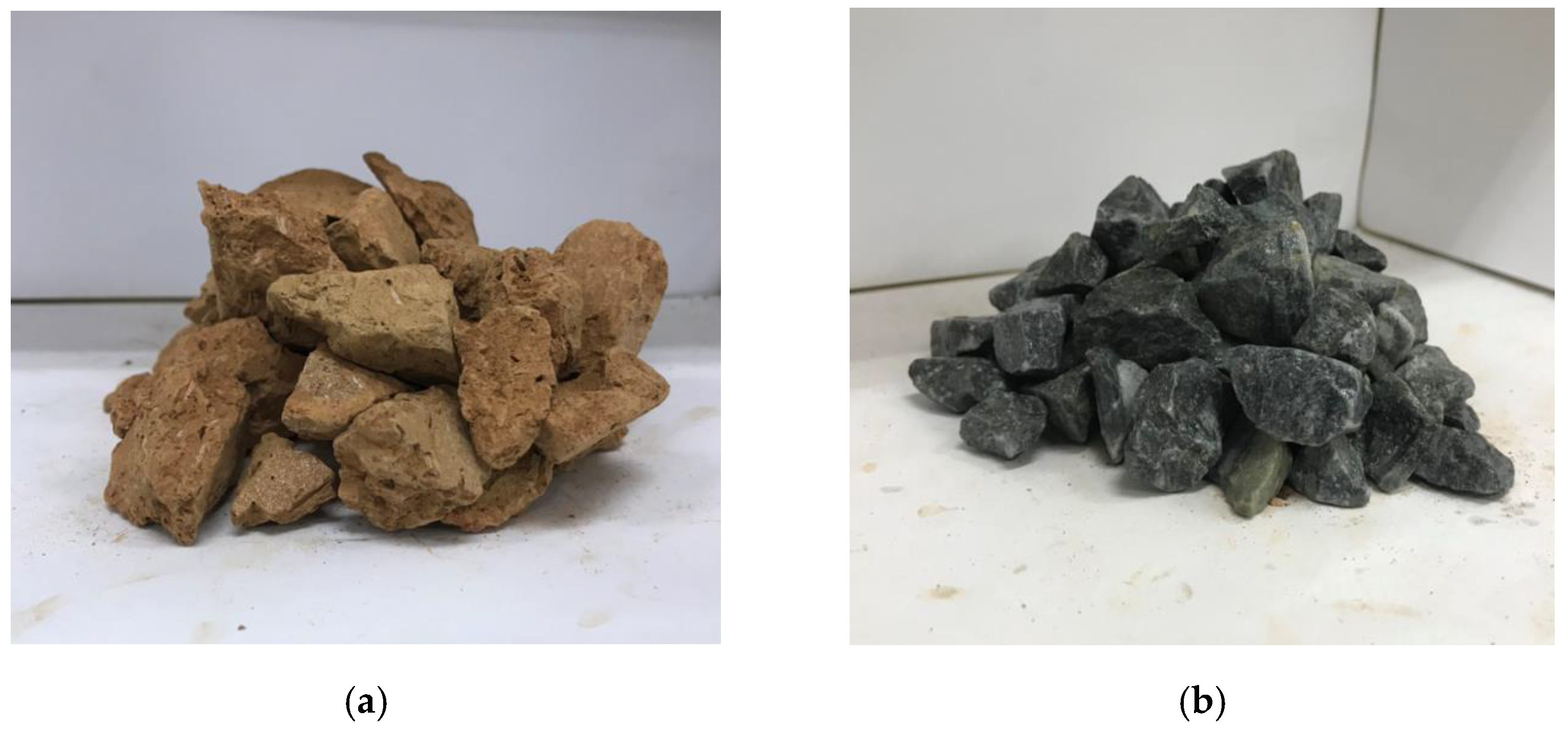
2.2. Material Properties

The solid clay bricks were crushed using a brick-crushing machine. The crushed brick aggregates were sieved to obtain coarse brick aggregates with sizes ranging from 5 mm to 20 mm (Figure 1a). The mechanical properties of the bricks were estimated by following the recommendations of ASTM C1314-21 and ASTM C140/C140M-22a [45,46]. The estimated mechanical properties of the bricks are reported in Table 2. However, the standard density of natural aggregates was approximately 2000–2900 kg/m3. Actual density tests were not considered in this study for natural aggregates. The replacement ratio of natural coarse aggregates with brick aggregates was 50% (Figure 1b). The target concrete strengths were 15 MPa and 25 MPa for the low-strength and high-strength concrete, respectively. The mix proportions adopted for the two concrete strengths are shown in Table 3. The ultimate tensile strain and strength of LC-GFRP wraps were 2.04% and 377.64 MPa, respectively, which were determined by following ASTM D3039/D3039M-17 [45]. The thickness of the LC-GFRP sheet was 0.50 mm.

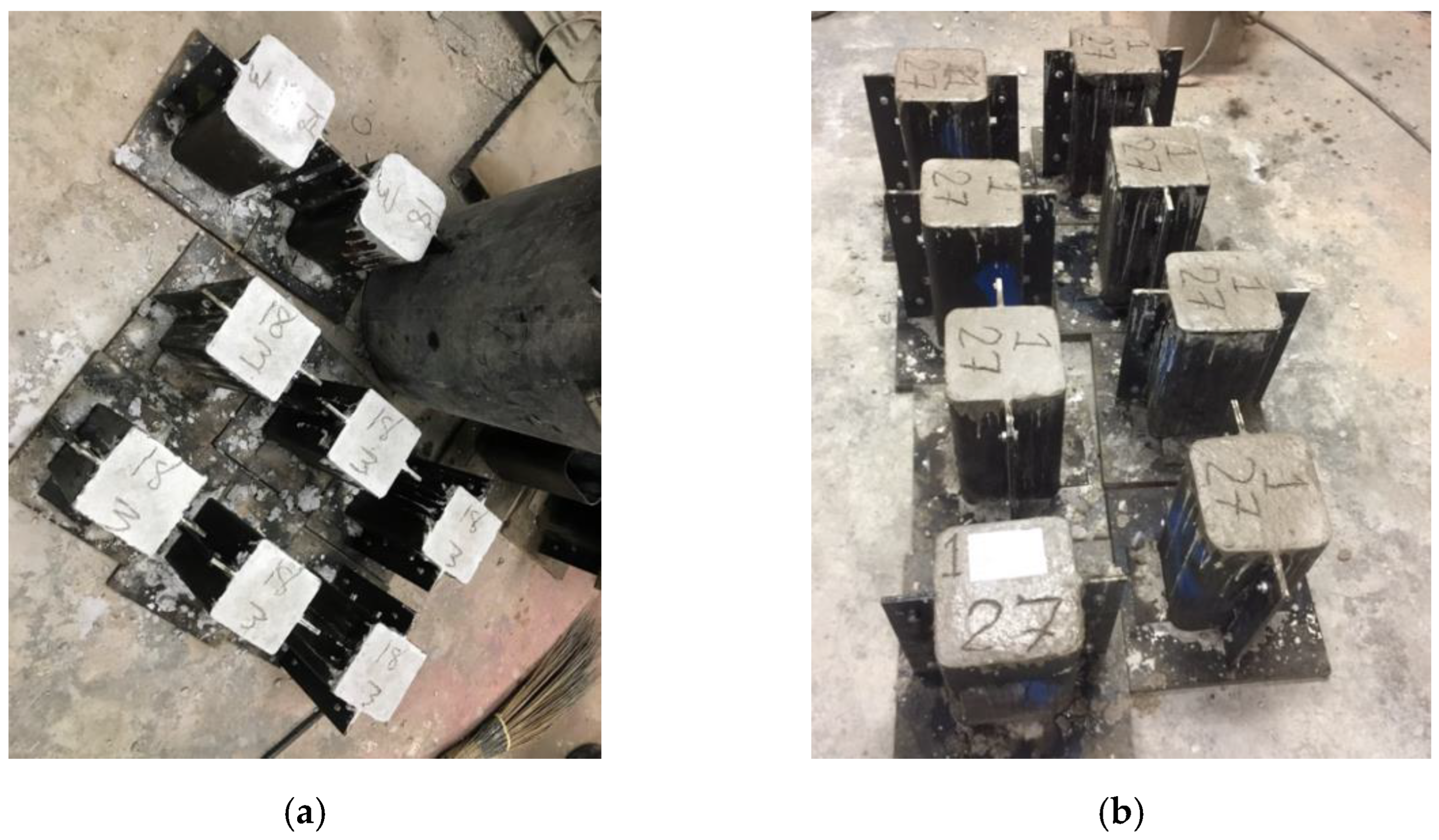
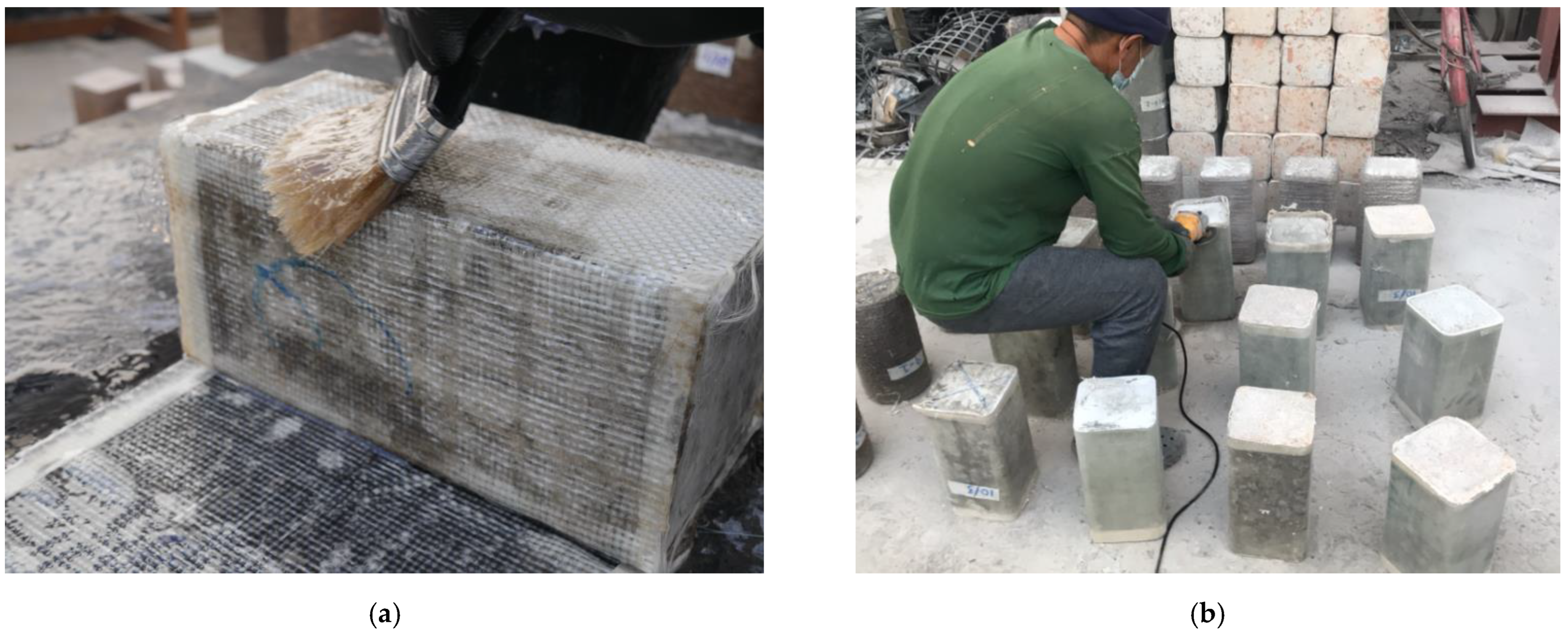
2.3. Details and Construction of Test Specimens

Each specimen measured 150   mm × 150   mm in cross-section and 300 mm in height to achieve the height-to-width ratio of 2.0. All of the specimens were cast in steel molds of the same dimensions. However, the steel molds were round to a corner radius of 26 mm for the Group 2 specimens, as shown in Figure 2a, whereas the rectilinear-shaped molds were used for the Group 1 specimens. The concrete was poured in three equal layers in each mold, whereas proper compaction (using vibrating poker) was applied to each layer. The specimens were taken out of the molds after one day of casting and cured for 28 days in laboratory environments (i.e., temperature was approximately 30–33 degree centigrade and humidity was 65–75%). The strengthening of specimens was performed after their curing by using a hand layout.
The surface of each specimen was properly cleaned and smoothed before applying GFRP. Epoxy resin was applied to the concrete surface by using a hand brush to impregnate the surface. This was followed by wrapping GFRP around the specimens. The first layer of GFRP was epoxy impregnated using a brush (see Figure 3a), before the application of the second layer. This process was repeated for the subsequent GFRP layers. Finally, the extended GFRP sheets above and below the top and bottom surfaces were ground, as shown in Figure 3b.

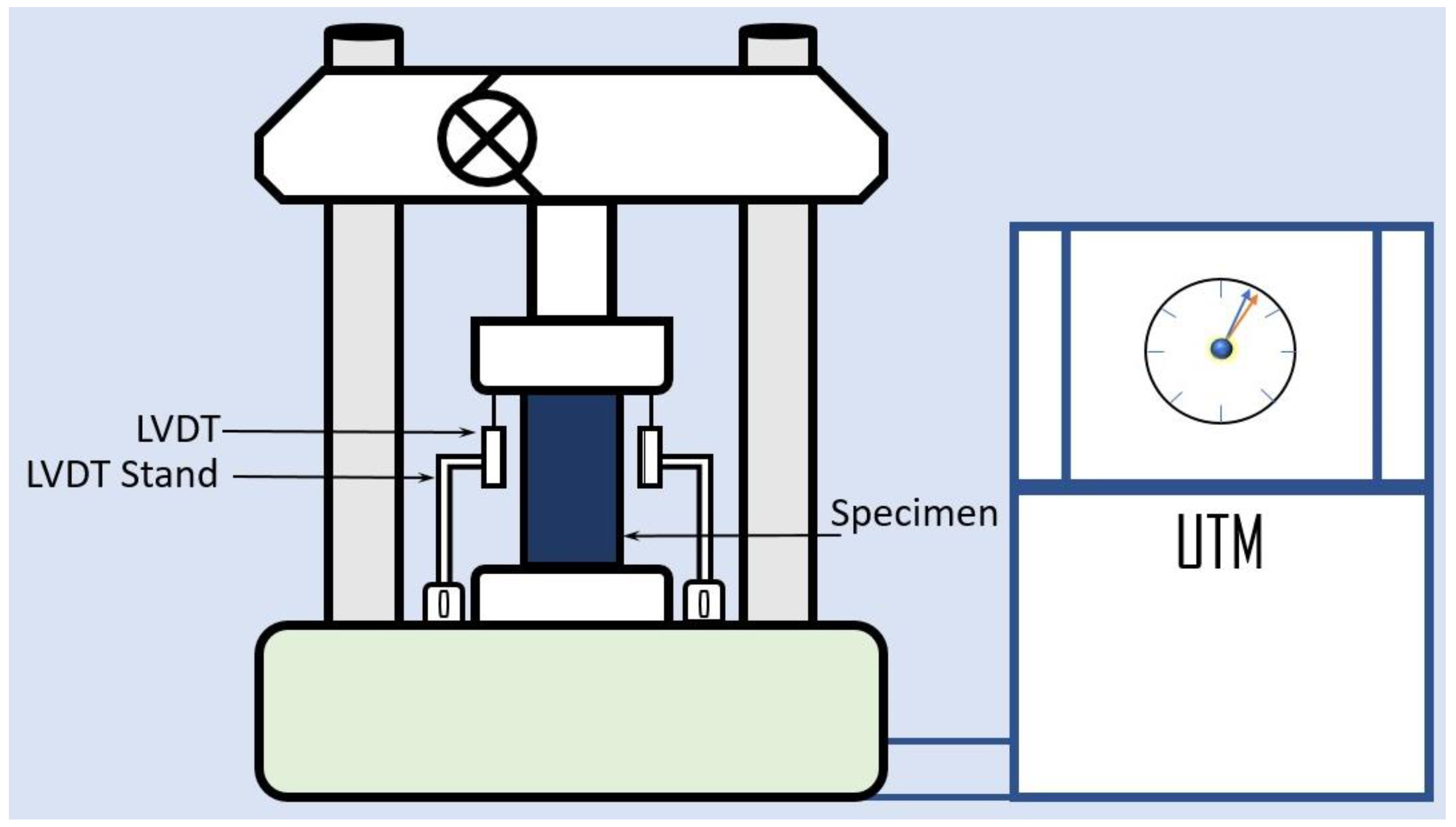
2.4. Test Setup and Instrumentation

A monotonic compressive load was applied to each specimen by using a hydraulic Universal Testing Machine. The ultimate capacity of universal testing machine was 200 tons. A calibrated load cell was deployed to measure the intensity of the applied compressive load, whereas a logger recorded the measured load. A uniform application of the load was achieved by placing steel plates above and below the specimen, as shown in Figure 4. The axial shortening of the specimens under the applied compressive load was simultaneously measured by using two linear variable differential transducers (LVDTs). The recorded deflection was subsequently converted to the strain, whereas the recorded load was converted to compressive stress by utilizing the geometrical dimensions of specimens.

3. Experimental Results

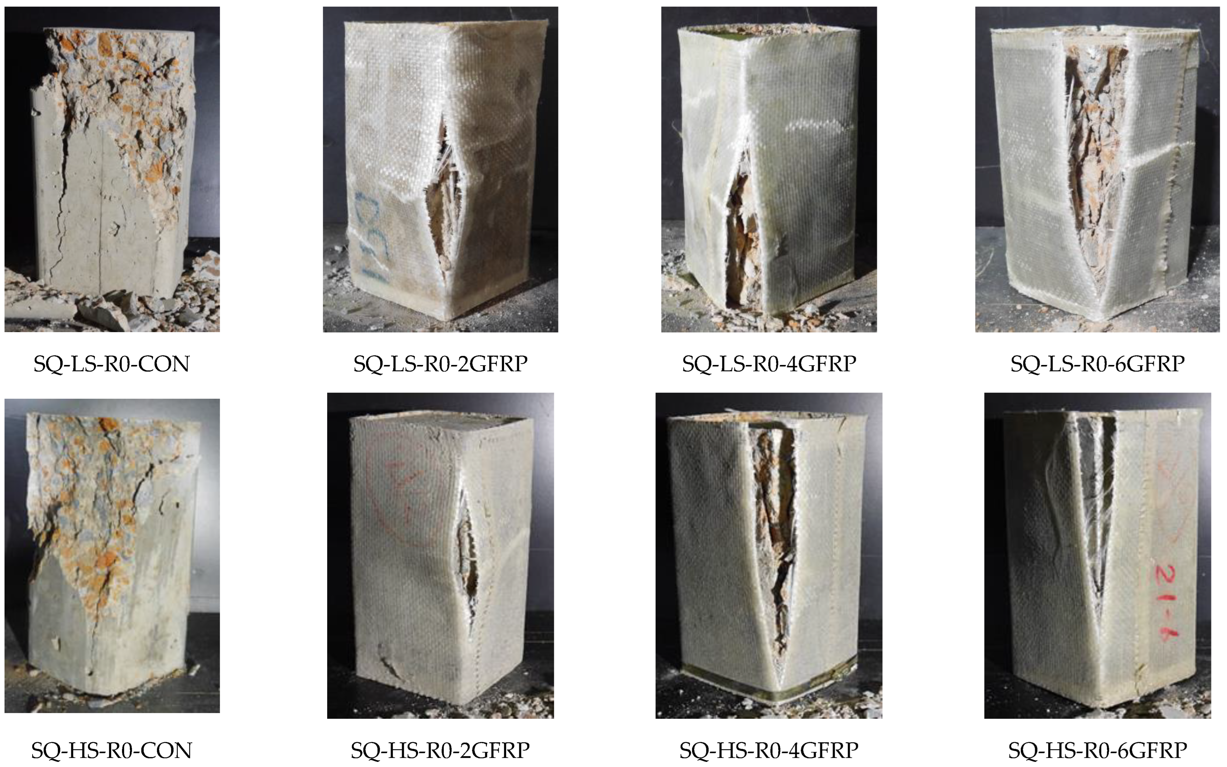
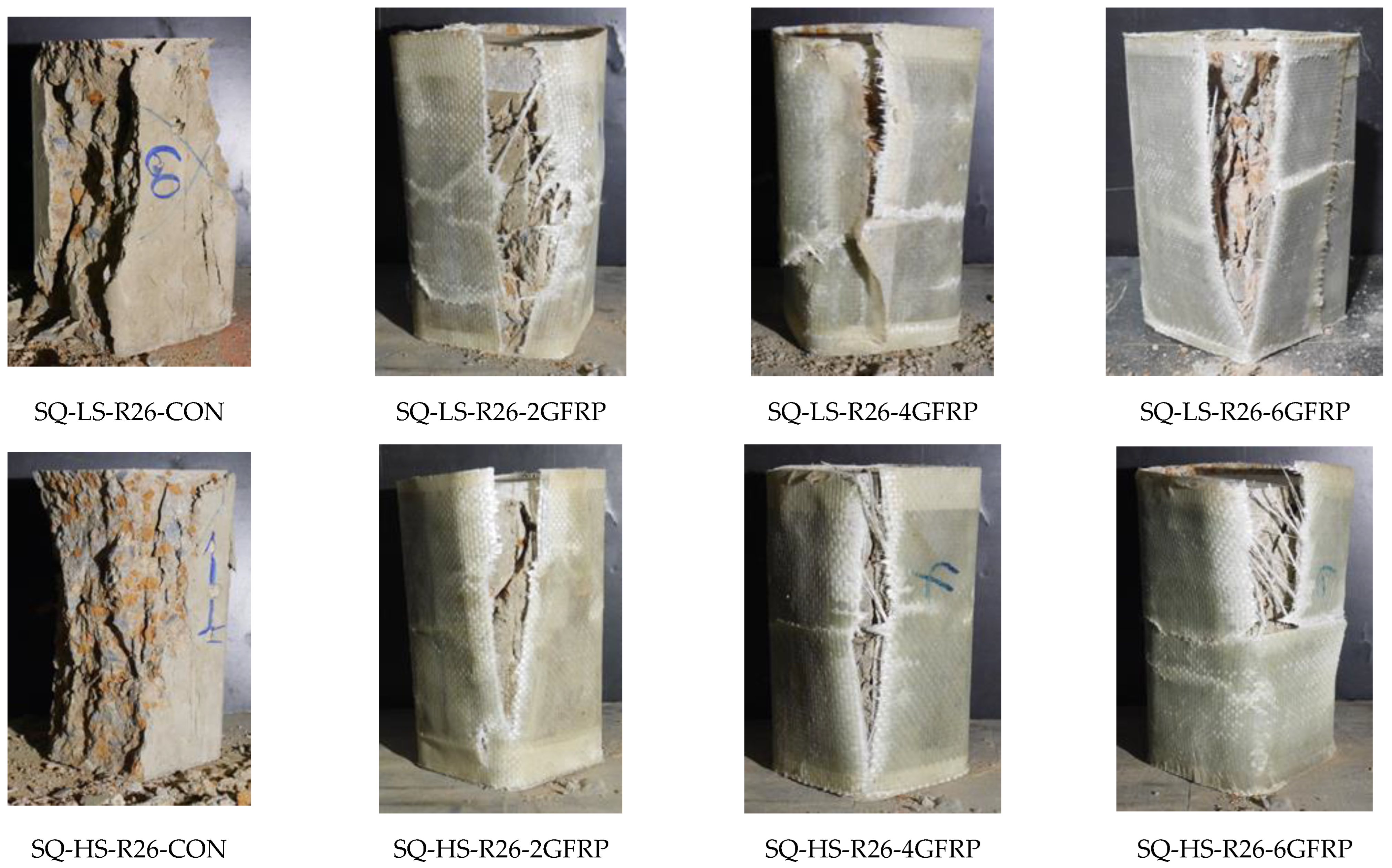
3.1. Ultimate Failure Modes

The ultimate failure modes of Group 1 specimens are shown in Figure 5. The failure of the two control specimens was due to the sudden concrete crushing and splitting within the top half of their heights. The stress concentrations near the sharp corners of rectilinear concrete specimens are known to exist [43,44]. To avoid premature failure due to these stress concentrations, ACI 440.2R-02 [47] recommends a minimum corner radius of 13 mm. Since no corner radius was provided in the Group 1 specimens, the failure accompanied the rupture of GFRP sheets at the corners, as shown in Figure 5. The resulting failure was brittle, irrespective of the concrete strength and the number of GFRP layers. This suggests that premature failure due to stress concentrations could not be prevented even with the application of six GFRP layers. This could be associated with the relatively lower ultimate strain of GFRP, i.e., 2.04%. Future studies are required to further explore this phenomenon by using FRP composites with higher rupture strains, such as polyester fiber ropes [42].
The failure modes of the Group 2 specimens are shown in Figure 6. In the same way as the control specimens in Group 1, the failure of the Group 2 control specimens was brittle. However, the crushing and splitting propagated all along the full height. The low-strength-strengthened specimens in Group 2 failed due to the rupture of the GFRP sheets in the hoop direction. For the two and four GFRP layers, the tensile rupture of GFRP sheets was found to occur between the corners suggesting that the stress concentrations were mitigated successfully. Specimen SQ-LS-R26-6GFRP failed by the rupture of GFRP sheets at the corners. This can be attributed to the resulting high compressive strength of Specimen SQ-LS-R26-6GFRP due to six GFRP layers that may have eventually resulted in higher stress concentrations near the corners as compared to those in Specimens SQ-LS-R26-2GFRP and SQ-LS-R26-4GFRP. The failure of high-strength concrete specimens in Group 2 also exhibited rupture of GFRP sheets mainly near the corners, and a similar analogy of high-stress concentrations near the corners can be made due to the high concrete strength.

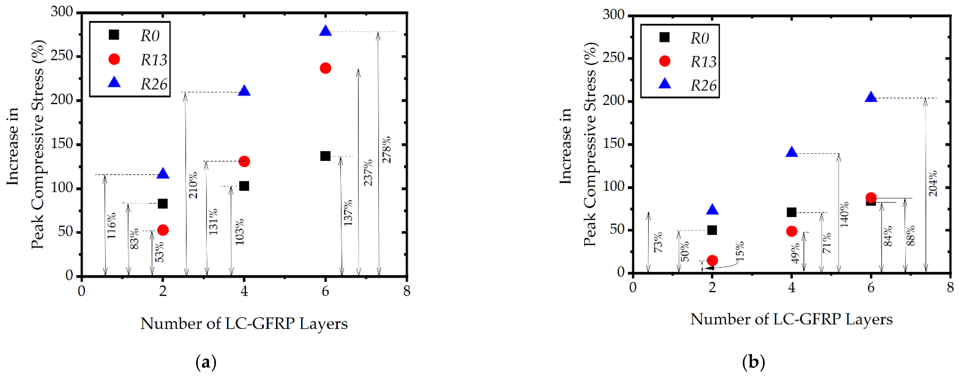
3.2. Peak Stress and Ultimate Strain

A summary of the peak compressive stress sustained and the ultimate strain for all of the specimens is presented in Table 4. The average peak stress for control specimen SQ-LS-R0-CON was slightly higher than the control specimen SQ-LS-R26-CON. This could be associated with the larger bearing area of the SQ-LS-R0-CON specimen as compared to the control specimen SQ-LS-R26-CON. The low-strength concrete specimens demonstrated an 83%, 103%, and 137% increase in the peak compressive stress due to two, four, and six GFRP wraps, respectively. The corresponding improvement in the ultimate strain was observed at 82%, 194%, and 658%, respectively. Similarly, a considerable improvement in the peak compressive stress of high-strength specimens in Group 1 was also observed as two, four, and six GFRP wraps enhanced the peak compressive stress by 50%, 71%, and 84%, respectively, whereas the enhancement in ultimate strain was 70%, 159%, and 134%, respectively. Group 2 specimens also demonstrated a substantial improvement in the peak compressive stress and strain. The peak compressive stress of the low-strength specimens was improved by 116%, 210%, and 278%, respectively. At the same time, the ultimate strain was enhanced by 222%, 495%, and 752%, respectively. The high-strength specimens exhibited an increase of 84%, 364%, and 563% for the peak compressive stress due to two, four, and six GFRP layers, respectively, whereas the ultimate strain was increased by 84%, 364%, and 563%, respectively. The above discussion concerning Table 4 suggests that the LC-GFRP resulted in a substantial improvement in the peak compressive stress and ultimate strain, which is crucial given the brittle nature of the concrete. Overall, the % increase in peak stresses of the GFRP-confined specimens with 0 mm corner radius was lower than the GFRP-confined specimens with a 26 mm corner radius due to the premature rupture of LC-GFRP at sharp corners.

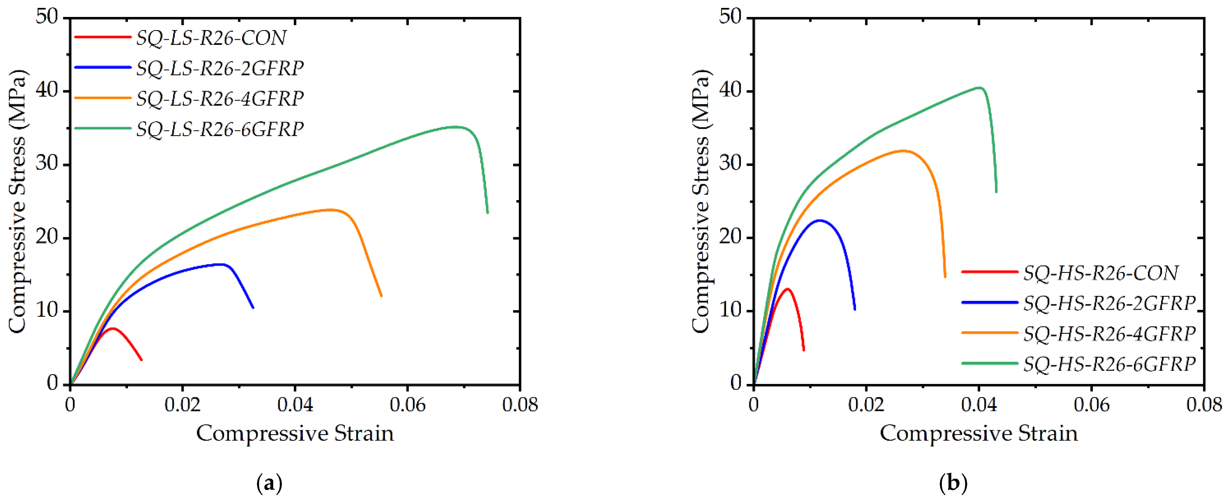
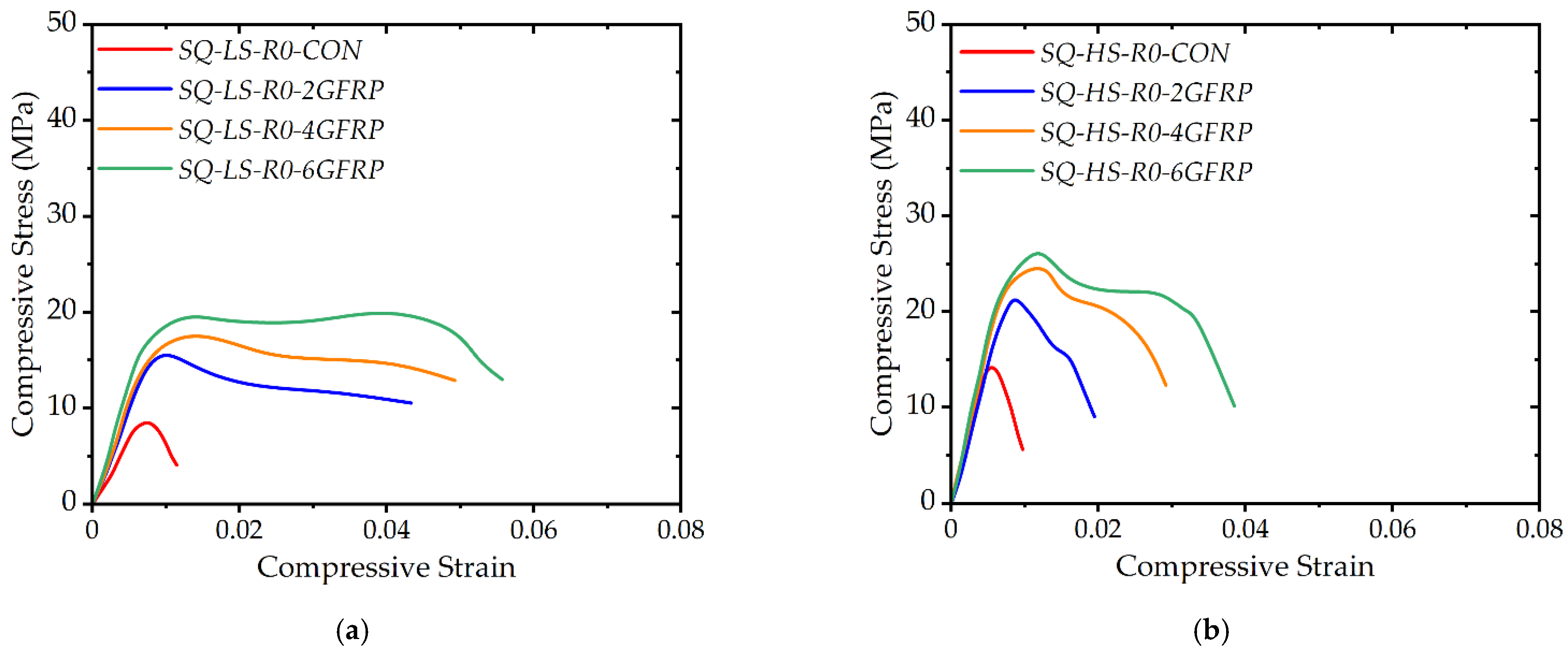
3.3. Compressive Stress-Strain Curves

The recorded stress–strain behavior of Group 1 specimens is shown in Figure 7. Figure 7a shows the stress–strain curves for the low concrete strength specimens in Group 1. It is evident that a substantial improvement in the peak compressive stress was observed. The important parameter to be observed is the range of strain for which the peak sustained stress was maintained. This suggests that LC-GFRP imparted a considerable ductility to the concrete, which is crucial for strengthening against dynamic loads. The post-peak behavior of Specimens SQ-LS-R0-2GFRP and SQ-LS-R0-4GFRP was descending, whereas a stable second branch was observed for Specimen SQ-LS-R0-6GFRP. On the contrary, the second branch of the compressive stress–strain curves of the high-strength specimens in Group 1 was descending irrespective of the number of LC-GFRP layers. The second difference in Figure 7a,b is the value of the ultimate strain. The high-strength specimens were able to sustain compressive stress to lower strain values as compared to low-strength specimens.
Figure 8a,b shows stress–strain curves for Group 2 specimens with low and high concrete strength, respectively. A significant difference between Figure 7 and Figure 8 is observed in the second branch. It is recalled that the sharp corners in the Group 2 specimens were rounded to a 26 mm corner radius. The corresponding result is depicted in Figure 8a, as the stiff initial branch was followed by an ascending branch highlighting the importance of the corner radius. The peak compressive stress and the ultimate strain were found to increase with the number of LC-GFRP sheets. However, the improvement in the axial ductility was limited by the concrete strength. It is evident in Figure 8 that the failure of the high concrete strength specimens for the same number of LC-GFRP layers occurred at lower strains than those of the low concrete strength specimens. This could be related with the lower lateral dilation of the high-strength concrete as compared to the low-strength concrete.

3.4. Effect of Concrete Strength and Corner Radius

The effect of the concrete strength on the gain in peak compressive stress due to LC-GFRP confinement is shown in Figure 9. It is evident that the gain in peak compressive stress is dependent on the concrete strength. For both of the groups and for the same number of LC-GFRP layers, the specimens with low concrete strength demonstrated greater improvement in the peak compressive stress than high strength specimens. Another observation that can be made from Figure 9 is the effect of corner radius on the improvement in peak compressive stress. For the case of no corner radius (see Figure 9a), the maximum increase in the peak compressive stress observed for Specimen SQ-LS-R0-6GFRP was 137%, whereas the corresponding value for a 26 mm corner radius was 278%, observed for Specimen SQ-LS-R26-6GFRP.
The effect of concrete strength on the improvement in ultimate strain is exhibited in Figure 10. A similar trend as that for the peak compressive stress is observed. This is evident as the low-strength specimens demonstrated a greater improvement in their ultimate strains than the high-strength specimens. The second branch of stress–strain curves of the Group 1 specimens was either descending or stable, whereas an ascending second branch was observed for the Group 2 specimens. As a result, the Group 2 specimens demonstrated a higher increase in the peak compressive stress.

4. Analytical Investigations

4.1. Existing Analytical Models
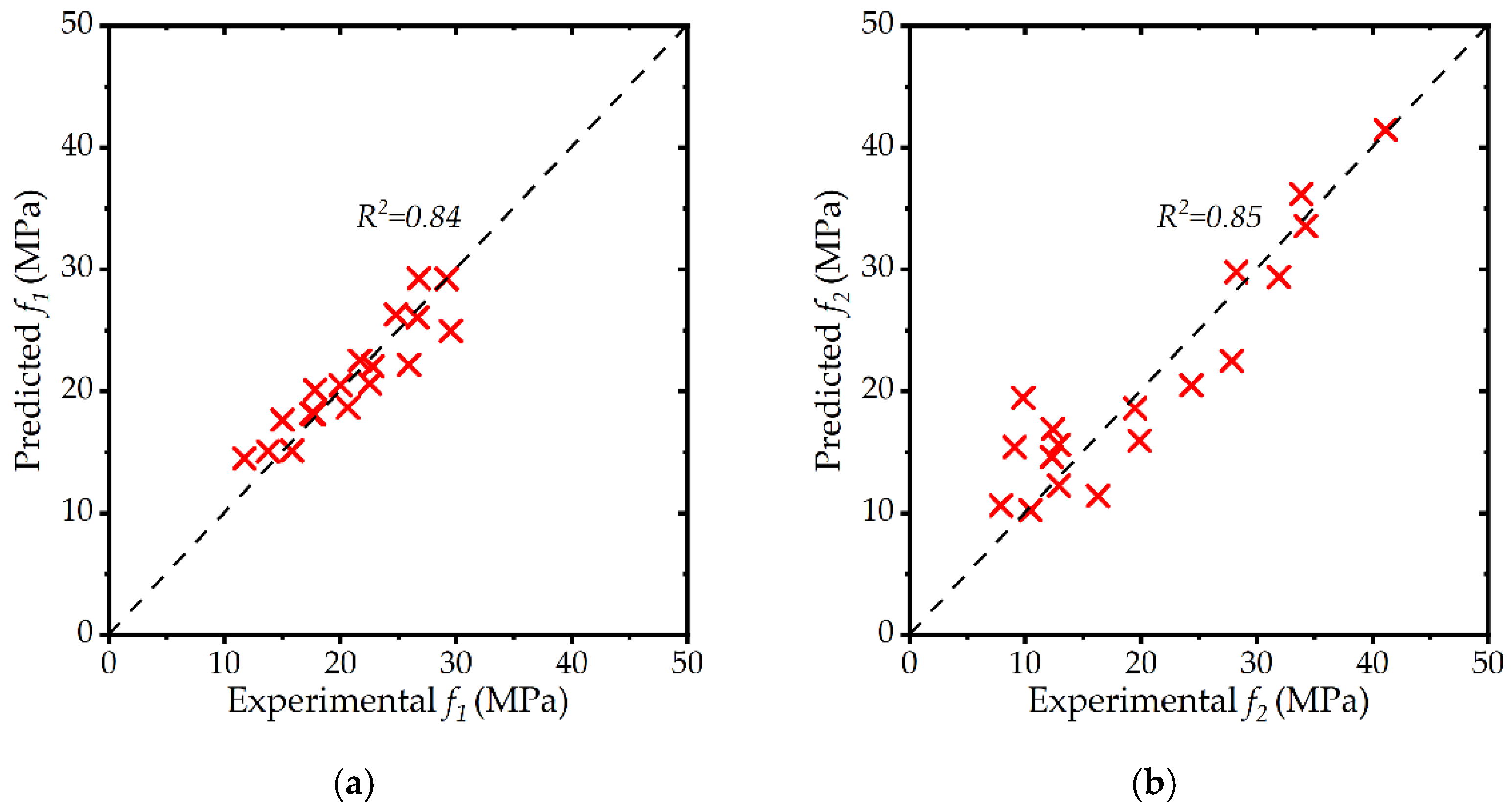
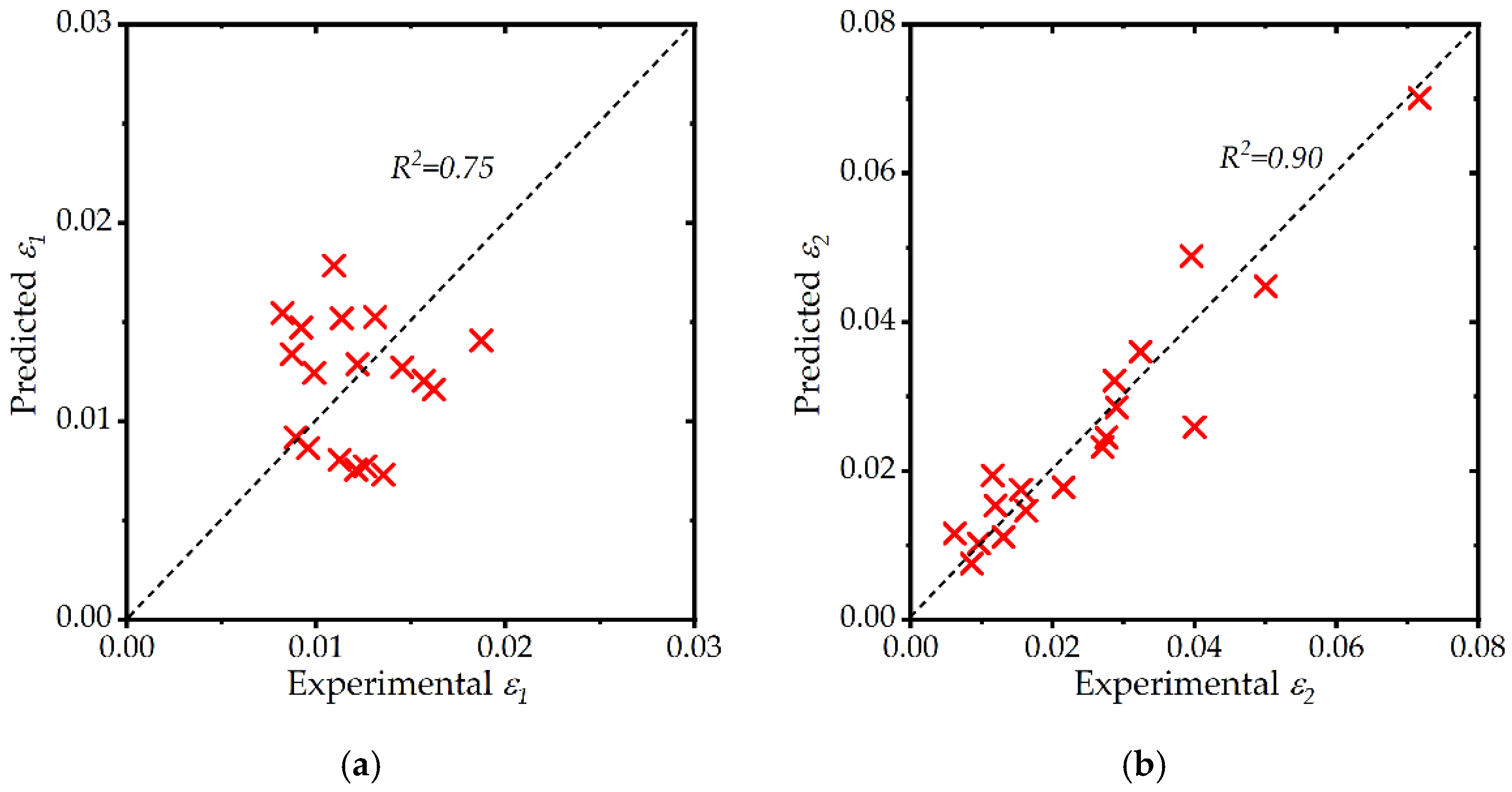
The accurate prediction of the peak compressive strength and the ultimate strain of strengthened concrete is important from both the design and analysis considerations. In existing studies, the confined concrete peak strength is often related to the lateral confinement pressure that is generated by the external confinement as:
f c c f c o = 1 + k 1 ( f l f c o )
where f c o is the compressive strength of unconfined concrete; f l is the lateral pressure generated by external confinement; and k 1 is the regression constant and varies for different existing models. The confining pressure f l is computed by taking an equilibrium between the outward core pressure and the resulting forces generated within the confinement, as shown in Figure 11. The resulting equilibrium equation is defined as [44]:
f l = 2 f f r p t D × ρ
where f f r p is the tensile strength of external wrap; t is the thickness of external wrap; and D is the diagonal length of the rectilinear section, which is defined as [48]:
D = 2 b d b + d  
where b and d are the cross-sectional dimensions of the section. The parameter ρ in Equation (2) is defined as [48]:
ρ = 1 ( b 2 r ) 2 + ( d 2 r ) 2 3 A
where r is the corner radius and A is the cross-sectional area defined as:
A = b d ( 4 π ) r 2
The ultimate strain of the confined concrete ϵ c c can be expressed in a similar way as:
ϵ c c ϵ c o = 1 + k 2 ( f l f c o )
where ϵ c o is the ultimate strain of unconfined concrete and k 2 is the regression constant. Several numerical models are available in the literature to relate the peak compressive stress f c c and the ultimate strain ϵ c c to the confining pressure exerted by external FRPs. Several existing peak compressive stress and ultimate strain models are presented in Table 5. In a recent study by Rodsin et al. [42], it was found that the accuracy of the models in Table 5 varied with the concrete strength. Further, the model of Hussain et al. [44] closely approximated the peak compressive stress of LC-GFRP-confined concrete. It was further found that none of the models in Table 5 were able to provide good agreement with experimental ultimate strain results. Therefore, further studies were recommended to increase the database of LC-GFRP-confined concrete specimens to propose equations for the peak compressive stress and ultimate strain.
The accuracy of the models in Table 5 is shown in Figure 12 to predict the peak compressive stress of LC-GFRP-confined concrete. Unlike the findings of Rodsin et al. [42], the model of Hussain et al. [44] underestimated the peak compressive stress of LC-GFRP-confined specimens with zero corner radius (see Figure 12a,b), whereas the models of ACI 2002 [48] and Lam and Teng [52] seem to provide good agreement with experimental results. For specimens in Group 2, the model of Hussain et al. [44] seems to correlate well with the experimental results along with the model of ACI 2002 [48]. From the study by Rodsin et al. [42] and the present study, it can be seen that none of the considered models were able to provide good agreement with the experimental peak compressive stresses on a consistent basis.
The accuracy of the considered models to predict the ultimate strain of LC-GFRP-confined RBAC specimens is shown in Figure 13. In general, none of the models was able to predict the ultimate strains on a consistent basis. Therefore, it was desired to propose peak compressive stress and ultimate strain models for LC-GFRP-confined RBAC.

4.2. Proposed Model

Regression analysis was performed to propose equations for the peak compressive stress, and the ultimate strain of LC-GFRPP-confined RBAC. Six specimens tested by Rodsin et al. [42] were also included to increase the sample size. It should be mentioned that the samples tested by Rodsin et al. [42] incorporated a corner radius of 13 mm as opposed to the 26 mm corner radius in the present study. Figure 14 presents the effect of the corner radius on the increase in the peak compressive stress of RBAC due to LC-GFRP confinement. In general, it is observed that the increase in the peak compressive stress for the same layers of LC-GFRP and concrete strength is improved as the corner radius is increased. Therefore, the effect of the corner radius must be included in the proposed equation of peak compressive stress. Secondly, it is observed that the increase in the peak compressive stress is more in Figure 14a (low-strength concrete) than in Figure 14b (high-strength concrete). Therefore, the effect of unconfined concrete must also be included. Finally, the effect of the lateral confining pressure due to LC-GFRP confinement is also evident in Figure 14 as the compressive stress increases with the increase in the layers of LC-GFRP.
The regression analysis was performed to predict equations for four quantities, mainly peak compressive stress f 1 and corresponding strain ϵ 1 , ultimate stress f 2 and the corresponding strain ϵ 2 as shown in Figure 15. The nonlinear regression analysis was conducted using the classical Gauss–Newton method, and the analysis was performed using SPSS Statistics. It was discussed in Section 3 that both ascending and descending behavior was observed in the second branch of the stress–strain curves depending upon the concrete strength and corner radius. Equations (7) and (8) were found to correlate well with the experimental results of f 1 and f 2 by considering unconfined concrete strength f c o , the confining pressure f l , and corner radius r :
f 1 f c o = 1 + 1.841 ( b r b ) 0.51 ( f l f c o ) 0.55
f 2 f c o = 1 + 0.101 ( b r b ) 7.63 ( f l f c o ) 0.73 ( f 1 f c o ) 2.95
The accuracy of Equations (7) and (8) is shown in Figure 16a,b, respectively. A good correlation between the experimental and predicted values of f 1 and f 2 .
Equations (9) and (10) were found to correlate with experimental ϵ 1 and ϵ 2 values and their accuracy is shown in Figure 17a,b, respectively. It can be seen that a good agreement between experimental and predicted ϵ 1 and ϵ 2 values is obtained.
ϵ 1 = ϵ c o ( 1 + 0.295 ( f l f c o ) 0.464 ( b r b ) 3.304 )
ϵ 2 = ϵ c o ( 1 + 7.853 ( f l f c o ) 1.30 ( b r b ) 2.579 )

5. Conclusions

This study investigated the role of low-cost glass-fiber-reinforced polymer (LC-GFRP) sheets as external passive confinement to enhance the mechanical properties of recycled brick aggregate concrete (RBAC). Thirty-two square RBAC specimens were constructed and tested in two groups depending upon the corner radius. The following important conclusions are drawn:
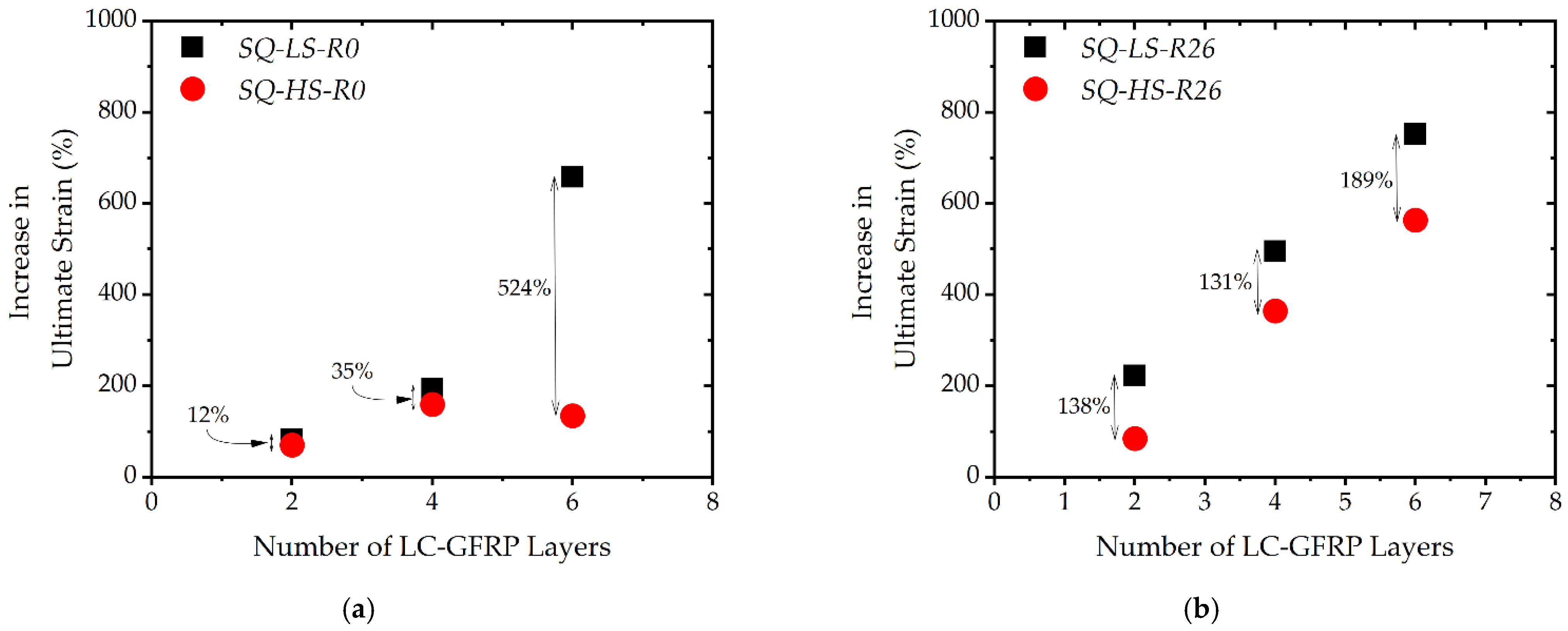
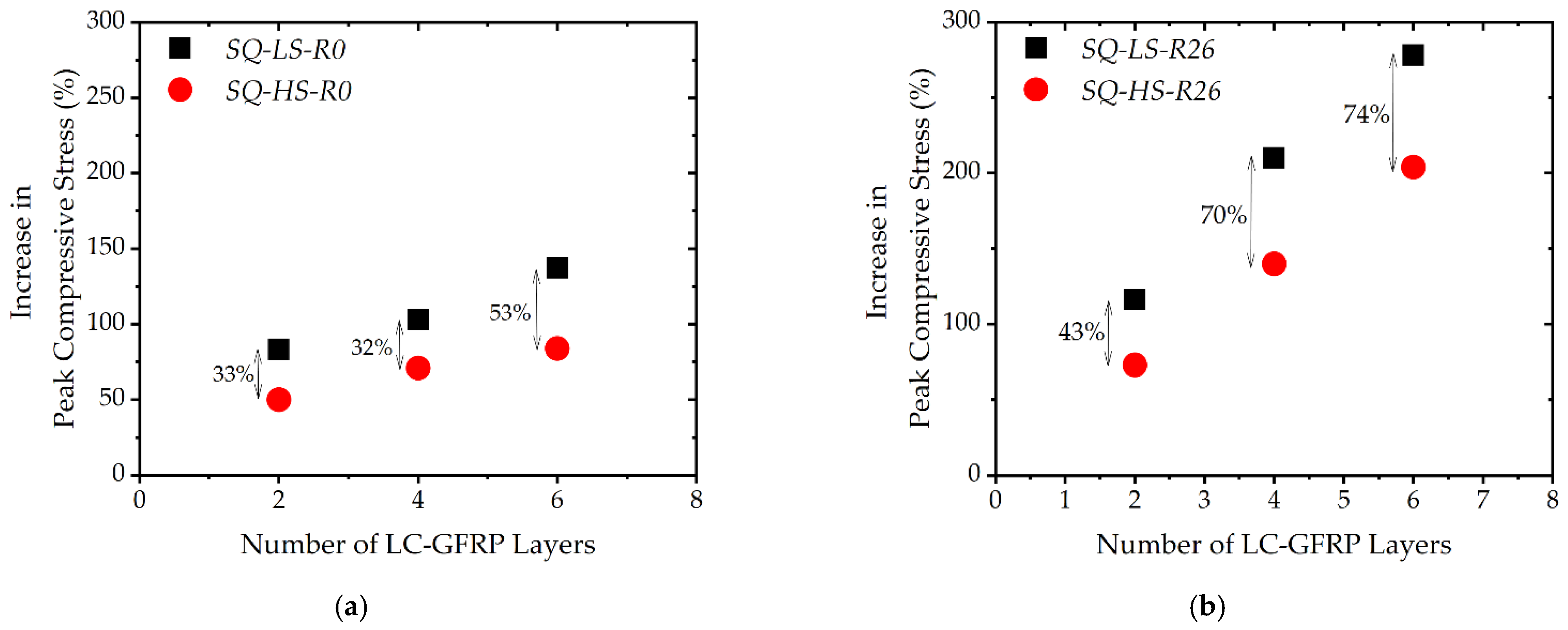
  • The peak compressive stress and ultimate strain were found to increase with the number of LC-GFRP wraps. The maximum increase in the peak compressive stress and the ultimate strain was observed for six LC-GFRP wraps;
  • It was found that the provision of a 26 mm corner radius significantly improved the efficiency of LC-GFRP wraps. Premature failure due to stress concentrations near sharp corners in specimens with zero corner radius undermined the efficacy of LC-GFRP wraps. Therefore, it is suggested to provide a corner radius to prevent this premature failure;
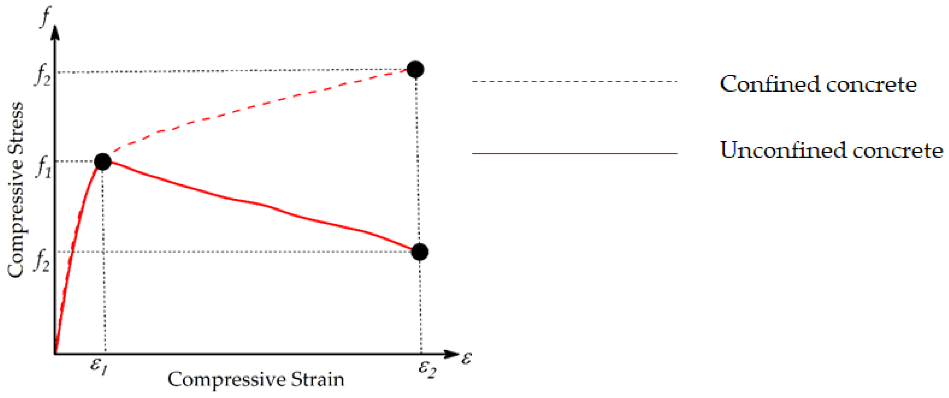
  • The shape of the compressive stress–strain curves of LC-GFRP-confined RBAC was bilinear. The initial stiff branch was identical in all of the strengthened specimens. The second branch was ascending and descending for the zero- and 26-mm corner radius, respectively. As a result, the ultimate stress of 26 mm corner radius specimens was higher;
  • A comparison between the strengthened specimens based on the concrete strength revealed that low-strength specimens demonstrated a higher increase in the peak compressive stress and strain as compared to high-strength specimens;
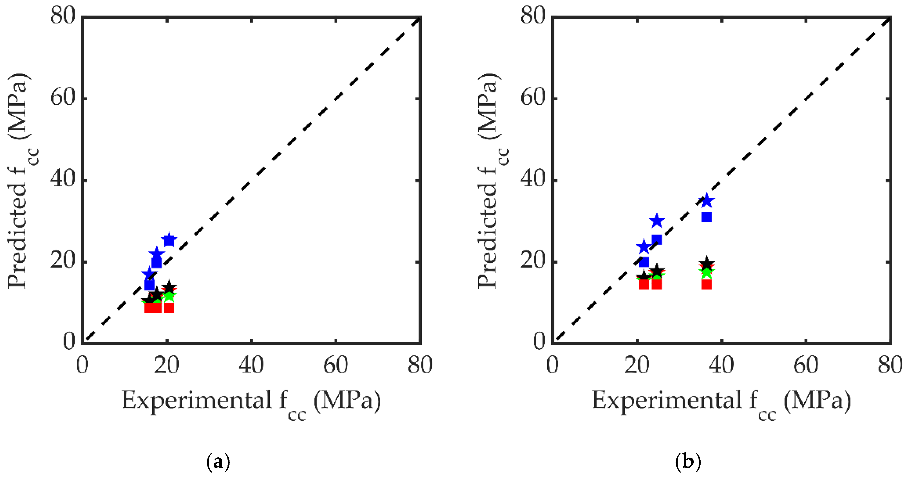
  • Existing FRP stress–strain models were found inconsistent in reproducing experimental results. Nonlinear regression analysis was conducted to propose equations for the key parameters in the stress–strain curves of LC-GFRP-confined RBAC.

6. Future Research Directions

This study employed the use of fired clay solid bricks to prepare the crushed brick aggregates. The density of these bricks is very low, i.e., 120 kg/m3. In actual practices, there are different types of bricks with varying densities. Future studies are recommended to consider crushed brick aggregates with higher densities to further investigate the role of LC-GFRP composites to enhance the strength of confined concrete.

Author Contributions

Conceptualization, R.P., K.R., K.C. and S.S.; Investigation, N.A. and Q.H.; Methodology, K.C. and K.K.; Validation, K.K.; Writing—original draft, R.P., K.R., K.C., N.A., S.S. and Q.H.; Writing—review & editing, R.P., K.R., N.A., S.S., Q.H. and K.K. All authors have read and agreed to the published version of the manuscript.

Funding

This research received no external funding.

Acknowledgments

This work was financially supported by King Mongkut’s Institute of Technology Ladkrabang Research Fund. The authors are thankful to Asian Institute of Technology (AIT) for supporting test facilities.

Conflicts of Interest

The authors declare no conflict of interest.

References

  1. Mehta, P.K.; Monteiro, P.J.M. Concrete: Microstructure, Properties, and Materials, 3rd ed.; McGraw-Hill: New York, NY, USA, 2006. [Google Scholar]
  2. Monteiro, P.J.; Miller, S.A.; Horvath, A. Towards sustainable concrete. Nat. Mater. 2017, 16, 698–699. [Google Scholar] [CrossRef]
  3. Noguchi, T.; Kitagaki, R.; Tsujion, M. Minimizing Environmental Impact and Maximizing Performance in Concrete Recycling. Struct. Concr. 2011, 12, 36–46. [Google Scholar] [CrossRef]
  4. Wong, C.L.; Mo, K.H.; Yap, S.P.; Alengaram, U.J.; Ling, T.C. Potential Use of Brick Waste as Alternate Concrete-Making Materials: A Review. J. Clean Prod. 2018, 195, 226–239. [Google Scholar] [CrossRef]
  5. Tang, Q.; Ma, Z.; Wu, H.; Wang, W. The Utilization of Eco-Friendly Recycled Powder from Concrete and Brick Waste in New Concrete: A Critical Review. Cem. Concr. Compos. 2020, 114, 103807. [Google Scholar] [CrossRef]
  6. He, Z.; Shen, A.; Wu, H.; Wang, W.; Wang, L.; Yao, C.; Wu, J. Research Progress on Recycled Clay Brick Waste as an Alternative to Cement for Sustainable Construction Materials. Constr. Build. Mater. 2021, 274, 122113. [Google Scholar] [CrossRef]
  7. Liu, Q.; Li, B.; Xiao, J.; Singh, A. Utilization Potential of Aerated Concrete Block Powder and Clay Brick Powder from C&D Waste. Constr. Build. Mater. 2020, 238, 117721. [Google Scholar] [CrossRef]
  8. Zhang, J.; Ding, L.; Li, F.; Peng, J. Recycled Aggregates from Construction and Demolition Wastes as Alternative Filling Materials for Highway Subgrades in China. J. Clean Prod. 2020, 255, 120223. [Google Scholar] [CrossRef]
  9. Andrew, G.H.T.; Tay, Y.W.I.; Annapareddy, A.; Li, M.; Tan, M.J. Effect of Recycled Glass Gradation in 3D Cementitious Material Printing. In Proceedings of the 3rd International Conference on Progress in Additive Manufacturing, Nanyang Technological University, Singapore, 14–17 May 2018; pp. 50–55. [Google Scholar]
  10. Ting, G.H.A.; Quah, T.K.N.; Lim, J.H.; Tay, Y.W.D.; Tan, M.J. Extrudable Region Parametrical Study of 3D Printable Concrete Using Recycled Glass Concrete. J. Build. Eng. 2022, 50, 104091. [Google Scholar] [CrossRef]
  11. Zhu, L.; Zhu, Z. Reuse of Clay Brick Waste in Mortar and Concrete. Adv. Mater. Sci. Eng. 2020, 2020, 6326178. [Google Scholar] [CrossRef]
  12. Li, H.; Dong, L.; Jiang, Z.; Yang, X.; Yang, Z. Study on Utilization of Red Brick Waste Powder in the Production of Cement-Based Red Decorative Plaster for Walls. J. Clean Prod. 2016, 133, 1017–1026. [Google Scholar] [CrossRef]
  13. Mansur, M.A.; Wee, T.H.; Cheran, L.S. Crushed Bricks as Coarse Aggregate for Concrete. Mater. J. 1999, 96, 478–484. [Google Scholar] [CrossRef]
  14. Khalaf, F.M. Using Crushed Clay Brick as Coarse Aggregate in Concrete. J. Mater. Civ. Eng. 2006, 18, 518–526. [Google Scholar] [CrossRef]
  15. Khalaf, F.M.; DeVenny, A.S. Recycling of Demolished Masonry Rubble as Coarse Aggregate in Concrete: Review. J. Mater. Civ. Eng. 2004, 16, 331–340. [Google Scholar] [CrossRef]
  16. Vrijders, J.; Desmyter, J. Een Hoogwaardig Gebruik van Puingranulaten Stimuleren; OVAM: Mechelen, Belgium, 2008. [Google Scholar]
  17. Debieb, F.; Kenai, S. The Use of Coarse and Fine Crushed Bricks as Aggregate in Concrete. Constr Build. Mater. 2008, 22, 886–893. [Google Scholar] [CrossRef]
  18. Medina, C.; Zhu, W.; Howind, T.; de Rojas, M.I.S.; Frías, M. Influence of Mixed Recycled Aggregate on the Physical—Mechanical Properties of Recycled Concrete. J. Clean. Prod. 2014, 68, 216–225. [Google Scholar] [CrossRef]
  19. Yang, J.; Du, Q.; Bao, Y. Concrete with Recycled Concrete Aggregate and Crushed Clay Bricks. Constr Build. Mater. 2011, 25, 1935–1945. [Google Scholar] [CrossRef]
  20. Nováková, I.; Mikulica, K. Properties of Concrete with Partial Replacement of Natural Aggregate by Recycled Concrete Aggregates from Precast Production. Procedia Eng. 2016, 151, 360–367. [Google Scholar] [CrossRef]
  21. Jiang, T.; Wang, X.M.; Zhang, W.P.; Chen, G.M.; Lin, Z.H. Behavior of FRP-Confined Recycled Brick Aggregate Concrete under Monotonic Compression. J. Compos. Constr. 2020, 24, 04020067. [Google Scholar] [CrossRef]
  22. Kox, S.; Vanroelen, G.; van Herck, J.; de Krem, H.; Vandoren, B. Experimental Evaluation of the High-Grade Properties of Recycled Concrete Aggregates and Their Application in Concrete Road Pavement Construction. Case Stud. Constr. Mater. 2019, 11, e00282. [Google Scholar] [CrossRef]
  23. Yang, Y.F.; Ma, G.L. Experimental Behaviour of Recycled Aggregate Concrete Filled Stainless Steel Tube Stub Columns and Beams. Thin-Walled Struct. 2013, 66, 62–75. [Google Scholar] [CrossRef]
  24. Ameli, M.; Ronagh, H.R.; Dux, P.F. Behavior of FRP Strengthened Reinforced Concrete Beams under Torsion. J. Compos. Constr. 2007, 11, 192–200. [Google Scholar] [CrossRef]
  25. Jiangfeng, D.; Shucheng, Y.; Qingyuan, W.; Wenyu, Z.; Jiangfeng, D.; Shucheng, Y.; Qingyuan, W.; Wenyu, Z. Flexural Behavior of RC Beams Made with Recycled Aggregate Concrete and Strengthened by CFRP Sheets. J. Build. Struct. 2019, 40, 71–78. [Google Scholar] [CrossRef]
  26. Smith, S.T.; Teng, J.G. FRP-Strengthened RC Beams. I: Review of Debonding Strength Models. Eng. Struct. 2002, 24, 385–395. [Google Scholar] [CrossRef]
  27. Harajli, M.H. Axial Stress–Strain Relationship for FRP Confined Circular and Rectangular Concrete Columns. Cem. Concr. Compos. 2006, 28, 938–948. [Google Scholar] [CrossRef]
  28. Spoelstra, M.R.; Monti, G. FRP-Confined Concrete Model. J. Compos. Constr. 1999, 3, 143–150. [Google Scholar] [CrossRef]
  29. Pimanmas, A.; Saleem, S. Dilation Characteristics of PET FRP–Confined Concrete. J. Compos. Constr. 2018, 22, 04018006. [Google Scholar] [CrossRef]
  30. Al-Salloum, Y.A. Compressive Strength Models of FRP-Confined Concrete. In Proceedings of the 1st Asia-Pacific Conference on FRP in Structures, APFIS 2007, Hong Kong, China, 12–14 December 2007; Volume 1, pp. 175–180. [Google Scholar]
  31. Eid, R.; Paultre, P. Compressive Behavior of FRP-Confined Reinforced Concrete Columns. Eng. Struct. 2017, 132, 518–530. [Google Scholar] [CrossRef]
  32. Gao, C.; Huang, L.; Yan, L.; Kasal, B.; Li, W. Behavior of Glass and Carbon FRP Tube Encased Recycled Aggregate Concrete with Recycled Clay Brick Aggregate. Compos. Struct. 2016, 155, 245–254. [Google Scholar] [CrossRef]
  33. Tang, Z.; Li, W.; Tam, V.W.Y.; Yan, L. Mechanical Behaviors of CFRP-Confined Sustainable Geopolymeric Recycled Aggregate Concrete under Both Static and Cyclic Compressions. Compos. Struct. 2020, 252, 112750. [Google Scholar] [CrossRef]
  34. Han, Q.; Yuan, W.Y.; Ozbakkaloglu, T.; Bai, Y.L.; Du, X.L. Compressive Behavior for Recycled Aggregate Concrete Confined with Recycled Polyethylene Naphthalate/Terephthalate Composites. Constr. Build. Mater. 2020, 261, 120498. [Google Scholar] [CrossRef]
  35. Zeng, J.J.; Zhang, X.W.; Chen, G.M.; Wang, X.M.; Jiang, T. FRP-Confined Recycled Glass Aggregate Concrete: Concept and Axial Compressive Behavior. J. Build. Eng. 2020, 30, 101288. [Google Scholar] [CrossRef]
  36. Iskander, M.G.; Hassan, M. State of the Practice Review in FRP Composite Piling. J. Compos. Constr. 1998, 2, 116–120. [Google Scholar] [CrossRef]
  37. Wang, X.; Wu, Z. Evaluation of FRP and Hybrid FRP Cables for Super Long-Span Cable-Stayed Bridges. Compos. Struct. 2010, 92, 2582–2590. [Google Scholar] [CrossRef]
  38. Chaiyasarn, K.; Hussain, Q.; Joyklad, P.; Rodsin, K. New Hybrid Basalt/E-Glass FRP Jacketing for Enhanced Confinement of Recycled Aggregate Concrete with Clay Brick Aggregate. Case Stud. Constr. Mater. 2021, 14, e00507. [Google Scholar] [CrossRef]
  39. Yoddumrong, P.; Rodsin, K.; Katawaethwarag, S. Seismic Strengthening of Low-Strength RC Concrete Columns Using Low-Cost Glass Fiber Reinforced Polymers (GFRPs). Case Stud. Constr. Mater. 2020, 13, e00383. [Google Scholar] [CrossRef]
  40. Rodsin, K.; Hussain, Q.; Suparp, S.; Nawaz, A. Compressive Behavior of Extremely Low Strength Concrete Confined with Low-Cost Glass FRP Composites. Case Stud. Constr. Mater. 2020, 13, e00452. [Google Scholar] [CrossRef]
  41. Rodsin, K. Confinement Effects of Glass FRP on Circular Concrete Columns Made with Crushed Fired Clay Bricks as Coarse Aggregates. Case Stud. Constr. Mater. 2021, 15, e00609. [Google Scholar] [CrossRef]
  42. Rodsin, K.; Ali, N.; Joyklad, P.; Chaiyasarn, K.; Zand, A.W.A.; Hussain, Q. Improving Stress-Strain Behavior of Waste Aggregate Concrete Using Affordable Glass Fiber Reinforced Polymer (GFRP) Composites. Sustainability 2022, 14, 6611. [Google Scholar] [CrossRef]
  43. Wang, L.M.; Wu, Y.F. Effect of Corner Radius on the Performance of CFRP-Confined Square Concrete Columns. Eng. Struct. 2008, 30, 493–505. [Google Scholar] [CrossRef]
  44. Hussain, Q.; Ruangrassamee, A.; Tangtermsirikul, S.; Joyklad, P.; Wijeyewickrema, A.C. Low-Cost Fiber Rope Reinforced Polymer (FRRP) Confinement of Square Columns with Different Corner Radii. Buildings 2021, 11, 355. [Google Scholar] [CrossRef]
  45. ASTM C1314-21; Standard Test Method for Compressive Strength of Masonry Prisms. ASTM: West Conshohocken, PA, USA, 2021.
  46. ASTM C140/C140M-22a; Standard Test Methods for Sampling and Testing Concrete Masonry Units and Related Units. ASTM: West Conshohocken, PA, USA, 2022.
  47. ASTM D3039/D3039M-17; Standard Test Method for Tensile Properties of Polymer Matrix Composite Materials. ASTM: West Conshohocken, PA, USA, 2017.
  48. Soudki, K.; Alkhrdaji, T. Guide for the Design and Construction of Externally Bonded FRP Systems for Strengthening Concrete Structures (ACI 440.2R-02). In Proceedings of the Structures Congress and Exposition, New York, NY, USA, 20–24 April 2005; pp. 1–8. [Google Scholar] [CrossRef]
  49. Shehata, I.A.E.M.; Carneiro, L.A.V.; Shehata, L.C.D. Strength of Short Concrete Columns Confined with CFRP Sheets. Mater. Struct. 2002, 35, 50–58. [Google Scholar] [CrossRef]
  50. Touhari, M.; Mitiche, R.K. Strength Model of FRP Confined Concrete Columns Based on Analytical Analysis and Experimental Test. Int. J. Struct. Integr. 2020, 11, 82–106. [Google Scholar] [CrossRef]
  51. Mirmiran, A.; Shahawy, M.; Samaan, M.; Echary, H.E.; Mastrapa, J.C.; Pico, O. Effect of Column Parameters on FRP-Confined Concrete. J. Compos. Constr. 1998, 2, 175–185. [Google Scholar] [CrossRef]
  52. Lam, L.; Teng, J.G. Strength Models for Fiber-Reinforced Plastic-Confined Concrete. J. Struct. Eng. 2002, 128, 612–623. [Google Scholar] [CrossRef]
Figure 1. (a) Brick aggregates, and (b) natural aggregates.
Sustainability 14 11221 g001
Figure 2. Steel molds for (a) zero corner radius and (b) 26 mm corner radius.
Sustainability 14 11221 g002
Figure 3. (a) Application of epoxy resin and (b) grinding of excessive GFRP portions and smoothening of the top and bottom surfaces.
Sustainability 14 11221 g003
Figure 4. Typical test setup and instrumentation.
Sustainability 14 11221 g004
Figure 5. Ultimate failure modes of Group 1 specimens.
Sustainability 14 11221 g005
Figure 6. Ultimate failure modes of Group 2 specimens.
Sustainability 14 11221 g006
Figure 7. Compressive stress vs. strain response for Group 1 specimens with (a) low concrete strength and (b) high concrete strength.
Sustainability 14 11221 g007
Figure 8. Compressive stress vs. strain response for Group 2 specimens with (a) low concrete strength and (b) high concrete strength.
Sustainability 14 11221 g008
Figure 9. Increase in peak compressive stress in (a) Group 1 and (b) Group 2.
Sustainability 14 11221 g009
Figure 10. Increase in ultimate strain in (a) Group 1 and (b) Group 2.
Sustainability 14 11221 g010
Figure 11. Equilibrium between core pressure and the resulting confining forces (b = width, d = depth, D = diagonal diameter, fl = lateral confining pressure, t = thickness of FRP).
Sustainability 14 11221 g011
Figure 12. Comparison of predicted vs. experimental peak compressive stresses of subgroups (a) SQ-LS-R0, (b) SQ-HS-R0, (c) SQ-LS-R26, and (d) SQ-HS-R26 [42,46,47,48,49,50].
Sustainability 14 11221 g012aSustainability 14 11221 g012b
Figure 13. Comparison of predicted vs. experimental ultimate strains of subgroups (a) SQ-LS-R0, (b) SQ-HS-R0, (c) SQ-LS-R26, and (d) SQ-HS-R26 [42,46,47,48,50].
Sustainability 14 11221 g013aSustainability 14 11221 g013b
Figure 14. Effect of corner radius on the increase in compressive stress (a) low strength concrete and (b) high strength concrete.
Sustainability 14 11221 g014
Figure 15. Proposed parameters on the stress–strain curve.
Sustainability 14 11221 g015
Figure 16. Comparison of experimental and predicted values of (a) f 1 and (b) f 2 .
Sustainability 14 11221 g016
Figure 17. Comparison of experimental and predicted values of (a) ϵ 1 and (b) ϵ 2 .
Sustainability 14 11221 g017
Table 1. Summary of tested specimens.
GroupNameStrengthCorner RadiusGFRPNumber
SQ-LS-R0-CONLow strengthR0-2
SQ-LS-R0-2GFRPLow strengthR022
SQ-LS-R0-4GFRPLow strengthR042
SQ-LS-R0-6GFRPLow strengthR062
1SQ-HS-R0-CONHigh strengthR0-2
SQ-HS-R0-2GFRPHigh strengthR022
SQ-HS-R0-4GFRPHigh strengthR042
SQ-HS-R0-6GFRPHigh strengthR062
SQ-LS-R26-CONLow strengthR26-2
SQ-LS-R26-2GFRPLow strengthR2622
SQ-LS-R26-4GFRPLow strengthR2642
2SQ-LS-R26-6GFRPLow strengthR2662
SQ-HS-R26-CONHigh strengthR26-2
SQ-HS-R26-2GFRPHigh strengthR2622
SQ-HS-R26-4GFRPHigh strengthR2642
SQ-HS-R26-6GFRPHigh strengthR2662
Table 2. Mechanical properties of solid clay bricks.
PropertyDensity ( k g / m 3 ) Compressive Strength (MPa)Water Absorption (%)
Value1203.1423.27
Table 3. Mix proportions for concrete.
Constituent (kg/m3)CementSandNatural AggregatesBrick AggregatesWater
Strength
Low261783522522313
High627806358358251
Table 4. Summary of the peak stress and the corresponding strain.
Specimen IDPeak Stress (MPa)Standard DeviationIncrease in Peak Stress (%)Ultimate Strain ϵ c c Increase in ϵ c c (%)
SQ-LS-R0-CON8.660.707-0.0053-
SQ-LS-R0-2GFRP15.874.243830.009682
SQ-LS-R0-4GFRP17.590.0001030.0155194
SQ-LS-R0-6GFRP20.511.4141370.0400658
SQ-HS-R0-CON14.414.950-0.0051-
SQ-HS-R0-2GFRP21.624.243500.008670
SQ-HS-R0-4GFRP24.670.707710.0131159
SQ-HS-R0-6GFRP26.482.121840.0119134
SQ-LS-R26-CON7.740.707-0.0084-
SQ-LS-R26-2GFRP16.711.4141160.0270222
SQ-LS-R26-4GFRP23.991.4142100.0500495
SQ-LS-R26-6GFRP29.298.4852780.0717752
SQ-HS-R26-CON13.392.121-0.0062-
SQ-HS-R26-2GFRP23.161.414730.011584
SQ-HS-R26-4GFRP32.071.4141400.0290364
SQ-HS-R26-6GFRP40.736.3642040.0414563
Table 5. Existing compressive stress–strain models.
IDModelUltimate StressUltimate Strain
1Hussain et al. [44] f c c f c o = 1 + 2.70 ρ 0.90 ( f l f c o ) ϵ c c ϵ c o = 2 + 10 ρ 1.10 ( f l f c o )
2ACI 2002 [48] f c c f c o = 1.254 + 2.254 1 + 7.94 f l f c o 2 f l f c o ϵ c c ϵ c o = 1.5 + 13 ( f l f c o ) ( ϵ f e ϵ c o ) 0.45
3Shehata et al. [49] f c c f c o = 1 + 0.85 ( f l f c o ) ϵ c c ϵ c o = 1 + 13.5 ( f l f c o )
4Touhari and Mitiche [50] f c c f c o = 1 + ( 1 ( ( π 2 ) 1 ) ( b 2 r ) 2 b 2 ) f l f c o ϵ c c ϵ c o = 2.3 + 7 ( 1 ( ( π 2 ) 1 ) ( b 2 r ) 2 b 2 ) f l f c o
5Mirmiran et al. [51] f c c f c o = 1 + 6.0 ( 2 r D ) ( f l 0.7 f c o ) -
6Lam and Teng [52] f c c f c o = 1 + 3.30 ( f l f c o ) ϵ c c ϵ c o = 1.75 + 12 ( f l f c o ) ( ϵ f e ϵ c o ) 0.45
Publisher’s Note: MDPI stays neutral with regard to jurisdictional claims in published maps and institutional affiliations.

